

Husqvarna 96093001200 User Manual
DRT900H
Owner's Manual / 96093001200 / 2009-12
532 43 08-18
SAFETY RULES
Safe Operation Practices for Walk-Behind Powered Ro ta ry Tillers
TRAINING
• Read the Manual care ful ly. Be thor ough ly fa mil iar with
the controls and the proper use of the equip ment.
Know how to stop the unit and disengage the controls
quickly.
• Never allow children to operate the equipment. Never
allow adults to op er ate the equipment without proper
instruction.
• Keep the area of operation clear of all persons, par tic u lar ly small children, and pets.
PREPARATION
• Thoroughly inspect the area where the equipment is
to be used and remove all foreign objects.
• Disengage all clutches and shift into neutral before
starting the engine (mo tor).
• Do not operate the equipment with out wearing ad e quate outer gar ments. Wear footwear that will im prove
footing on slippery surfaces.
• Handle fuel with care; it is highly flammable.
• Use an approved fuel container.
• Never add fuel to a running engine or hot engine.
• Fill fuel tank outdoors with extreme care. Never fill fuel
tank indoors.
• Replace gasoline cap securely and clean up spilled
fuel before restarting.
• Use extension cords and receptacles as specified by
the manufacturer for all units with electric drive motors
or electric starting motors.
• Never attempt to make any adjustments while the
engine (motor) is running (except where specifically
rec om mend ed by manufacturer).
OPERATION
• Do not put hands or feet near or under rotating parts.
• Exercise extreme caution when op er at ing on or cross ing gravel drives, walks, or roads. Stay alert for hidden
hazards or traffic. Do not carry pas sen gers.
• After striking a foreign object, stop the engine (motor),
remove the wire from the spark plug, thoroughly in spect
the tiller for any damage, and repair the damage before
restarting and op er at ing the tiller.
• Exercise caution to avoid slipping or falling.
• If the unit should start to vibrate ab nor mal ly, stop the
engine (motor) and check immediately for the cause.
Vi bra tion is generally a warning of trouble.
• Stop the engine (motor) when leaving the operating
position.
• Take all possible precautions when leav ing the ma chine
unattended. Disengage the tines, shift into neutral, and
stop the engine.
• Before cleaning, repairing, or inspecting, shut off the
engine and make certain all moving parts have stopped.
Disconnect the spark plug wire, and keep the wire away
from the plug to prevent accidental starting. Disconnect
the cord on electric motors.
• Do not run the engine indoors; exhaust fumes are
dangerous.
• Never operate the tiller without proper guards, plates,
or other safety protective devices in place.
• Keep children and pets away.
• Do not overload the machine capacity by attempting
to till too deep at too fast a rate.
• Never operate the machine at high speeds on slippery
surfaces. Look behind and use care when backing.
• Never allow bystanders near the unit.
• Use only attachments and accessories approved by
the manufacturer of the tiller.
• Never operate the tiller without good visibility or light.
• Be careful when tilling in hard ground. The tines may
catch in the ground and propel the tiller forward. If this
occurs, let go of the handlebars and do not restrain the
machine.
MAINTENANCE AND STORAGE
• Keep machine, attachments, and accessories in safe
work ing condition.
• Check shear pins, engine mounting bolts, and other
bolts at frequent intervals for proper tightness to be
sure the equip ment is in safe working condition.
• Never store the machine with fuel in the fuel tank inside
a building where ignition sources are present, such
as hot water and space heaters, clothes dryers, and
the like. Allow the engine to cool before storing in any
enclosure.
• Always refer to the operator’s guide instructions for
im por tant details if the tiller is to be stored for an extended period.
- IMPORTANT -
CAUTIONS, IMPORTANTS, AND NOTES ARE A MEANS OF
ATTRACTING ATTENTION TO IMPORTANT OR CRIT I CAL
IN FOR MA TION IN THIS MANUAL.
IMPORTANT: USED TO ALERT YOU THAT THERE IS A
POS SI BIL I TY OF DAM AG ING THIS EQUIP MENT.
NOTE: Gives essential information that will aid you to
better understand, incorporate, or execute a particular set
of instructions.
Look for this symbol to point out im por tant safety precautions. It means
CAUTION!!! BE COME ALERT!!! YOUR
SAFE TY IS INVOLVED.
CAUTION: Always disconnect spark
plug wire and place wire where it can not contact spark plug in order to pre vent ac ci den tal starting when setting
up, trans port ing, adjusting or making
re pairs.
WARNING
The engine exhaust from this product con tains
chem i cals known to the State of Cal i for nia to
cause cancer, birth defects, or other reproductive harm.
2

PRODUCT SPECIFICATIONS
Gasoline Capacity: 2 Quarts (1,89L)
Unleaded Regular
Oil (API-SG-SL): SAE 30 (Above 40°F/4°C)
(Capacity: 18.6 oz./0.55L) SAE 5w-30/10W-30
Spark Plug : NGK
(Gap: .030"/0.76mm) R BPR6ES
CONGRATULATIONS on your purchase of a new tiller. It
has been designed, en gi neered and manu fac tured to give
you the best pos sible de penda bil ity and per form ance.
Should you experience any prob lems you can not easily
remedy, please contact your nearest authorized service
center. We have com pe tent, well-trained tech ni cians and
the proper tools to service or repair this unit.
Please read and retain this manual. The in struc tions will
enable you to assemble and main tain your tiller prop erly.
Always observe the “SAFETY RULES”.
CUSTOMER RESPONSIBILITIES
• Read and observe the safety rules.
• Follow a regular schedule in maintaining, caring for
and using your tiller.
• Follow instructions under “Maintenance” and “Stor age”
sections of this Owner’s Manual.
WARNING:This unit is equipped with an internal combustion engine and should not be used on or near any unimproved forest-covered, brush-covered or grass covered
land unless the engine’s exhaust system is equipped with
a spark arrester meeting applicable local or state laws (if
any). If a spark arrester is used, it should be maintained
in effective work ing order by the operator.
In the state of California the above is required by law
(Section 4442 of the California Public Resources Code).
Other states may have similar laws. Federal laws apply on
federal lands. See your Sears Authorized Service Center/
Department for spark arrester. Refer to the Repair Parts
section of this manual for part number.
TABLE OF CONTENTS
SAFETY RULES ..........................................................2
CUSTOMER RESPONSIBILITIES ...............................3
PRODUCT SPECIFICATIONS .....................................3
ASSEMBLY ...............................................................4-6
OPERATION ...........................................................7-11
MAINTENANCE SCHEDULE ....................................12
MAINTENANCE ...................................................12-14
SERVICE & ADJUSTMENTS ...............................15-17
STORAGE .................................................................. 18
TROUBLESHOOTING ............................................... 19
REPAIR PARTS ....................................................20-26
3
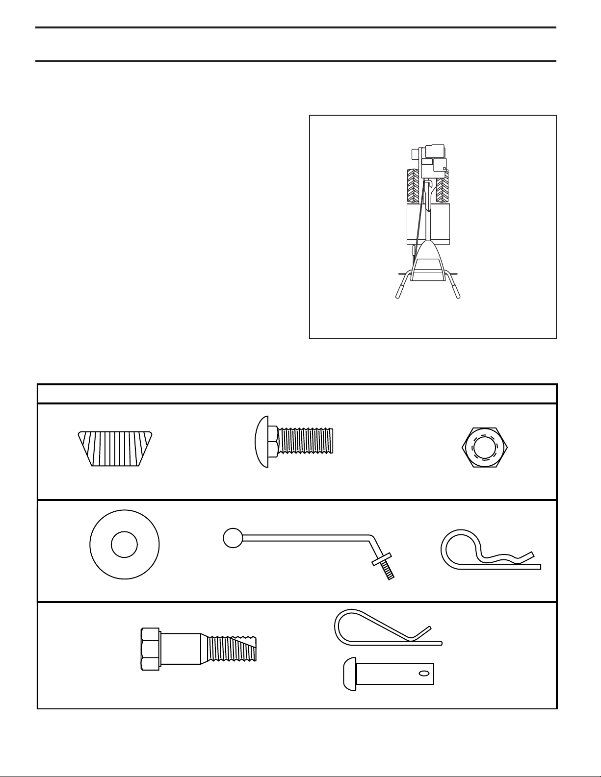
(1) Hairpin Clip
(1) Carriage Bolt
3/8-16 UNC x 1 Grade 5
(1) Center Locknut
3/8-16 UNC
(1) Handle Lock Lever
(1) Flat Washer 13/32 x 1 x 11 Gauge
CONTENTS OF HARDWARE PACK
(2) Handle Locks
(1) Pivot Bolt
3/8-16 UNC Grade 5
Extra Shear Pins & Clips
ASSEMBLY
Your new tiller has been assembled at the factory with exception of those parts left unassembled for shipping purposes.
To ensure safe and proper operation of your tiller all parts and hardware you assemble must be tightened securely. Use
the correct tools as necessary to insure proper tightness.
TOOLS REQUIRED FOR ASSEMBLY
A socket wrench set will make assembly easier. Standard
wrench sizes are listed.
(1) Utility knife
(1) Tire pressure gauge
(1) Pair of pliers
(1) 9/16" wrench
OPERATOR’S POSITION (See Fig. 1)
When right or left hand is mentioned in this manual, it
means when you are in the operating position (standing
behind tiller handles).
LEFT
FRONT
RIGHT
OPERATOR’S
POSITION
Fig. 1
4
ASSEMBLY
UNPACKING CARTON (See Fig. 2)
CAUTION: Be careful of exposed
sta ples when handling or disposing
of cartoning material.
IMPORTANT: WHEN UN PACK ING AND AS SEM BLING TILLER,
BE CAREFUL NOT TO STRETCH OR KINK CABLES.
• While holding handle assembly, cut cable ties se cur ing
handle assembly to top frame and depth stake. Let
handle assembly rest on tiller.
• Remove top frame of carton.
• Slowly ease handle assembly up and place on top of
carton.
• Cut down right hand front and right hand rear cor ners
of carton, lay side carton wall down.
• Remove packing material from handle assembly.
HANDLE
AS SEM BLY
carton_3
SHIFT ROD
Fig. 2
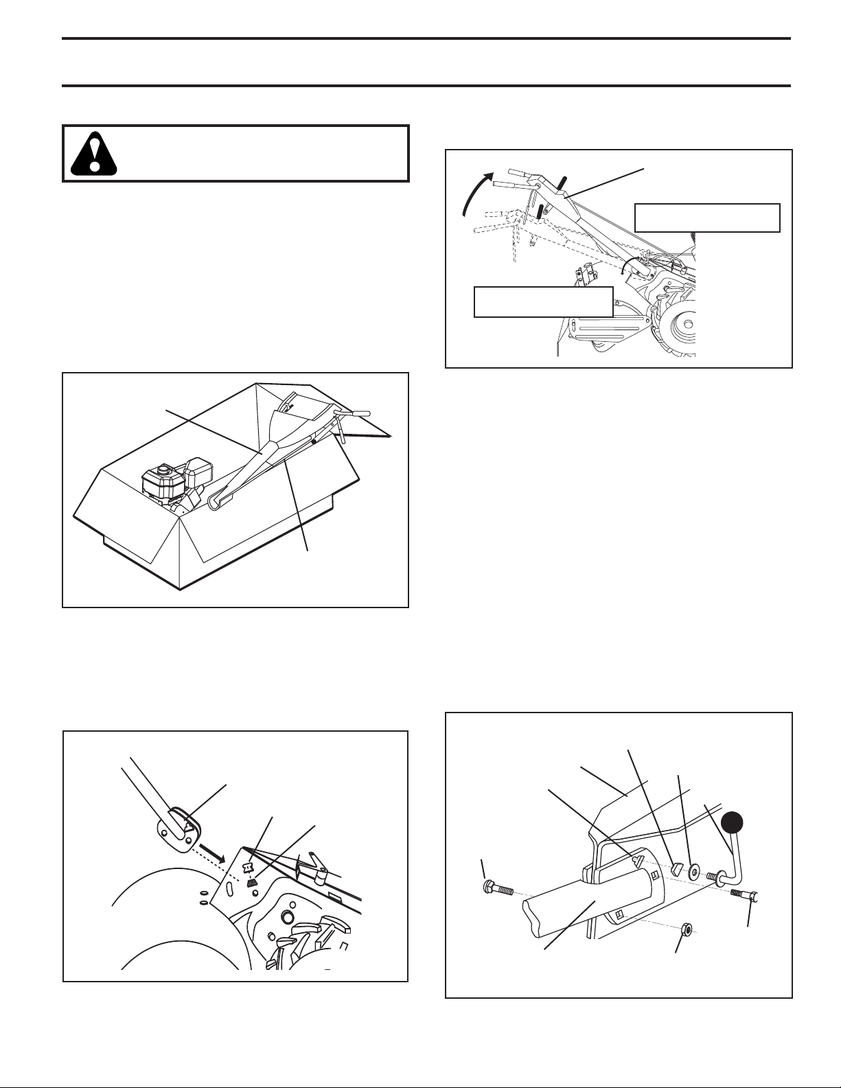
INSTALL HANDLE (See Figs. 3, 4, and 5)
• Insert one handle lock (with teeth facing outward) in
gearcase notch. (Apply grease on smooth side of
handle lock to aid in keeping lock in place until handle
assembly is lowered into position.)
VIEWED FROM R.H. SIDE OF TILLER
HANDLE ASSEMBLY
GEARCASE
NOTCH
HANDLE
LOCK
• Grasp handle assembly. Hold in “up” position. Be sure
handle lock remains in gearcase notch. Slide handle
assembly into position.
HANDLE ASSEMBLY
"UP" POSITION
TIGHTEN HANDLE LOCK
LEVER TO HOLD
LOOSEN HANDLE
LOCK LEVER TO MOVE
Fig. 4
• Rotate handle assembly down. Insert rear carriage bolt
first, with bolt head on L.H. side of tiller and loosely
assemble locknut (See Fig. 5).
• Insert pivot bolt in front part of plate and tighten.
• Cut down remaining corners of carton and lay panels
flat.
• Lower the handle assembly. Tighten nut on carriage
bolt so handle moves with some resistance. This will
allow for easier adjustment.
• Place flat washer on threaded end of handle lock lever.
• Insert handle lock lever through handle base and
gearcase. Screw in handle lock lever just enough to
hold lever in place.
• Insert second handle lock (with teeth in ward) in the
slot of the handle base (just inside of washer).
• With handle assembly in lowest position, securely
tight en handle lock lever by rotating clockwise. Leav ing handle assembly in lowest position will make it
easier to remove tiller from carton.
HANDLE
LOCK
GEARCASE
SLOT
CARRIAGE
BOLT
FLAT
WASHER
HANDLE LOCK
LEVER
Fig. 3
PIVOT BOLT
HANDLE
BASE
LOCKNUT
Fig. 5
5
ASSEMBLY
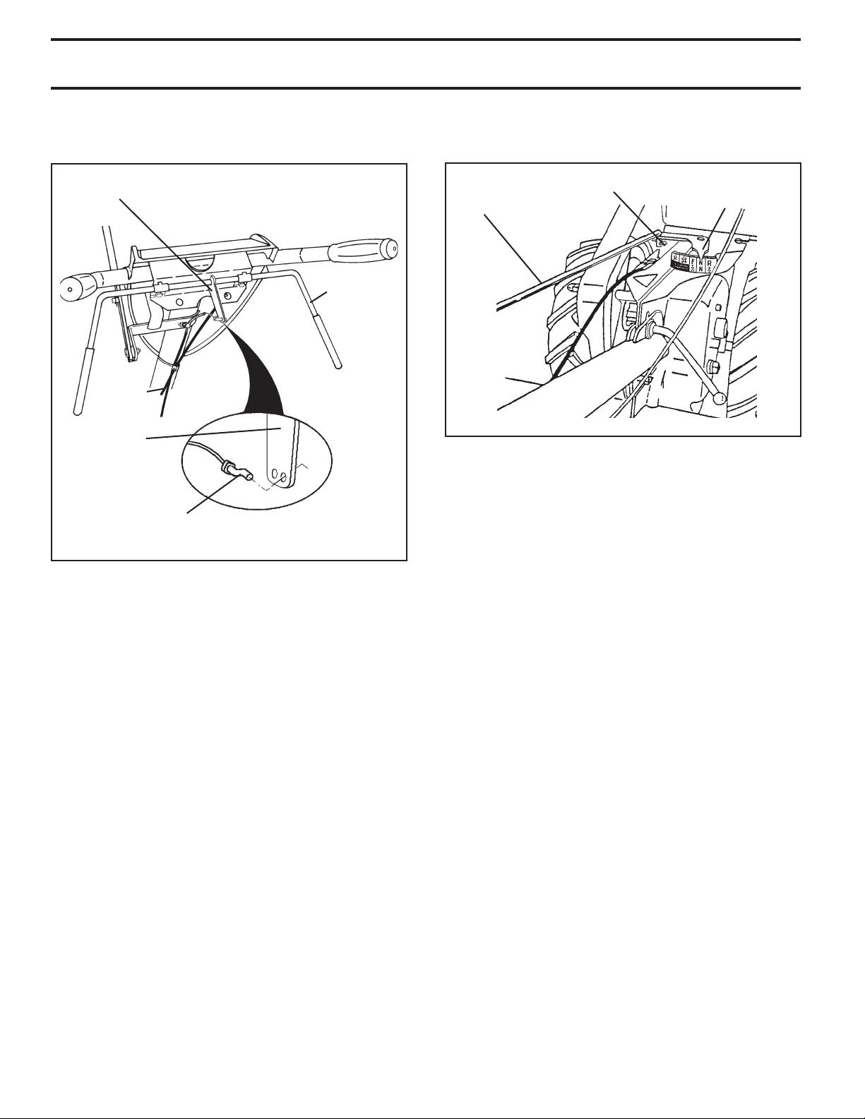
ATTACH CLUTCH CABLE (See Fig. 6)
• Hook end of clutch cable through hole in control bar
bracket.
CONTROL BAR
BRACKET
CONTROL
BAR
CLUTCH
CABLE
CONTROL BAR
BRACKET
END OF CLUTCH
CABLE
Fig. 6
CONNECT SHIFT ROD (See Fig. 7)
• Insert end of shift rod into hole of shift lever indicator.
• Insert hairpin clip through hole of shift rod to secure.
HAIRPIN
CLIP
SHIFT
ROD
SHIFT
LEVER
INDICATOR
Fig. 7
REMOVE TILLER FROM CRATE
• Make sure shift lever indicator is in “N” position (See
Fig. 7)
• Tilt tiller forward by lifting handle. Separate cardboard
cover from leveling shield.
• Rotate tiller handle to the right and pull tiller out of
carton.
CHECK TIRE PRESSURE
The tires on your unit were overinflated at the factory for
shipping purposes. Correct and equal tire pressure is
important for best tilling performance.
• Reduce tire pressure to 20 PSI (1.4 kg/cm2).
HANDLE HEIGHT
• Handle height may be adjusted to better suit operator.
(See “TO ADJUST HANDLE HEIGHT” in the Service
and Adjustments section of this manual).
6
CAUTION
OR WARNING
TILLING FORWARD NEUTRAL REVERSE
FAST SLOW
ENGINEONENGINE
OFF
OILFUELCHOKE
S
OPERATION
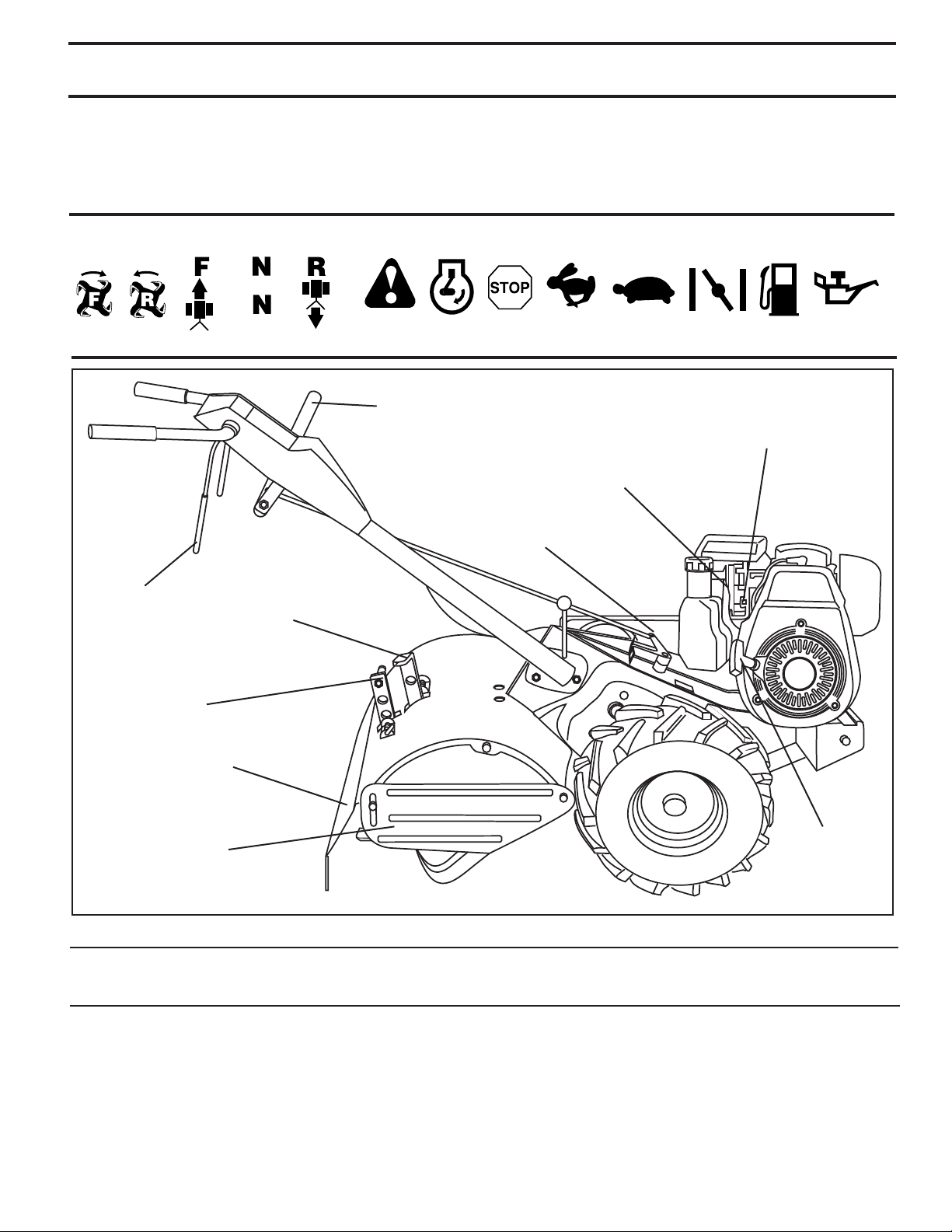
KNOW YOUR TILLER
READ THIS OWNER'S MANUAL AND SAFETY RULES BEFORE OPERATING YOUR TILLER.
Compare the illustrations with your tiller to familiarize yourself with the location of various controls and adjustments. Save
this manual for future reference.
These symbols may appear on your Tiller or in literature supplied with the product. Learn and understand their
meaning.
SHIFT LEVER
THROTTLE
CONTROL
CHOKE CONTROL
DRIVE
CONTROL
BAR
DEPTH STAKE
LEVELING
SHIELD
OUTER SIDE
SHIELD
Our tillers conform to the safety standards of the American National Standards Institute.
SHIFT LEVER IN DI CA TOR
DRAG
STAKE
RECOIL
STARTER
HANDLE
Fig. 8
MEETS ANSI SAFETY REQUIREMENTS
CHOKE CONTROL - Used when starting a cold engine.
THROTTLE CONTROL - Controls engine speed.
DEPTH STAKE - Controls depth at which tiller will dig.
DRAG STAKE - Controls forward speed in forward rotating
till position.
DRIVE CONTROL BAR - Used to engage tines.
LEVELING SHIELD - Levels tilled soil.
OUTER SIDE SHIELD - Adjustable to protect small plants
from being buried.
RECOIL STARTER HANDLE - Used to start the engine.
SHIFT LEVER - Used to shift transmission gears.
SHIFT LEVER INDICATOR - Shows which gear the trans-
mis sion is in.
7
OPERATION
00155
depth_stake_2
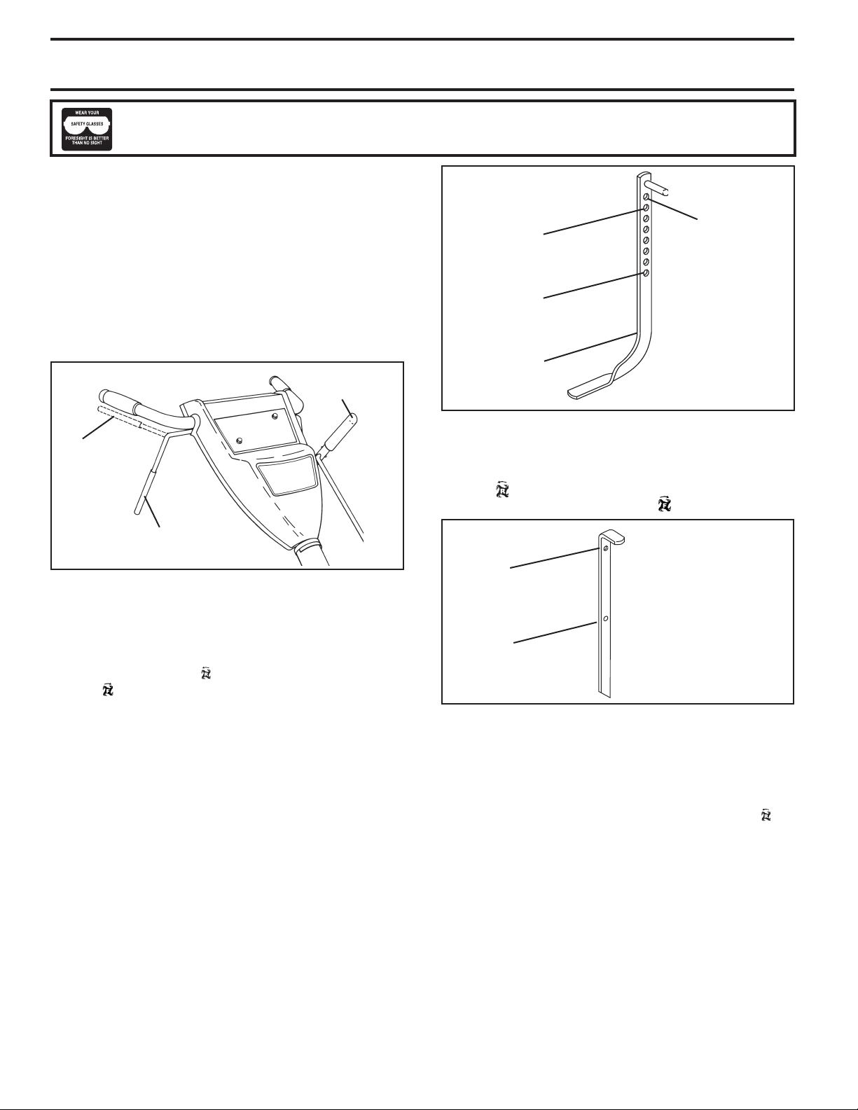
The operation of any tiller can result in foreign objects thrown into the eyes, which can result in
severe eye damage. Always wear safety glasses or eye shields before starting your tiller and while
tilling. We recommend a wide vision safety mask for over spectacles or standard safety glasses.
HOW TO USE YOUR TILLER
Know how to operate all controls before adding fuel and
oil or attempting to start engine.
STOPPING (See Fig. 9)
TINES AND DRIVE
• Release drive control bar to stop movement.
• Move shift lever to “N” (neutral) position.
ENGINE
• Move throttle control to “STOP” position.
• Never use choke to stop engine.
SHIFT
LEVER
SHALLOWEST
TILLING
(CULTIVATING)
DEEPEST
TILLING
DEPTH
STAKE
TRANSPORT
POSITION
Fig. 10
DRIVE CONTROL
BAR “ENGAGED”
PO SI TION
DRIVE CONTROL BAR
“DISENGAGED” PO SI TION
Fig. 9
TINE OPERATION - WITH WHEEL DRIVE
• Always release drive control bar before moving shift
lever into another position.
• Tine movement is achieved by moving shift lever to either
the counter rotating ( ) till position or the forward rotating (
) till position and engaging drive control bar.
FORWARD - WHEELS ONLY/TINES STOPPED
• Release drive control bar and move shift lever in di ca tor
to “F” (forward) position. Engage drive control bar and
tiller will move forward.
REVERSE - WHEELS ONLY/TINES STOPPED
• DO NOT STAND DIRECTLY BEHIND TILLER.
• Release the drive control bar.
• Move throttle control to “SLOW” position.
• Move shift lever indicator to “R” (reverse) position.
• Hold drive control bar against the handle to start tiller
movement.
HARD TO SHIFT GEARS
• Briefly engage drive control bar and release or rock tiller
forward and backward until are able to shift gears.
DEPTH STAKE (See Fig. 10)
The depth stake can be raised or lowered to allow you more
versatile tilling and cul ti vat ing, or to more easily transport
your tiller.
DRAG STAKE (See Fig. 11)
The drag stake should be raised when tilling in the counter
rotating ( ) till position. The drag stake should be lowered
when tilling in the forward rotating ( ) till position.
LOWERED
(FOR WARD ROTATING
TILL)
RAISED
(COUNTER ROTATING
TILL)
depth_stake_10
Fig. 11
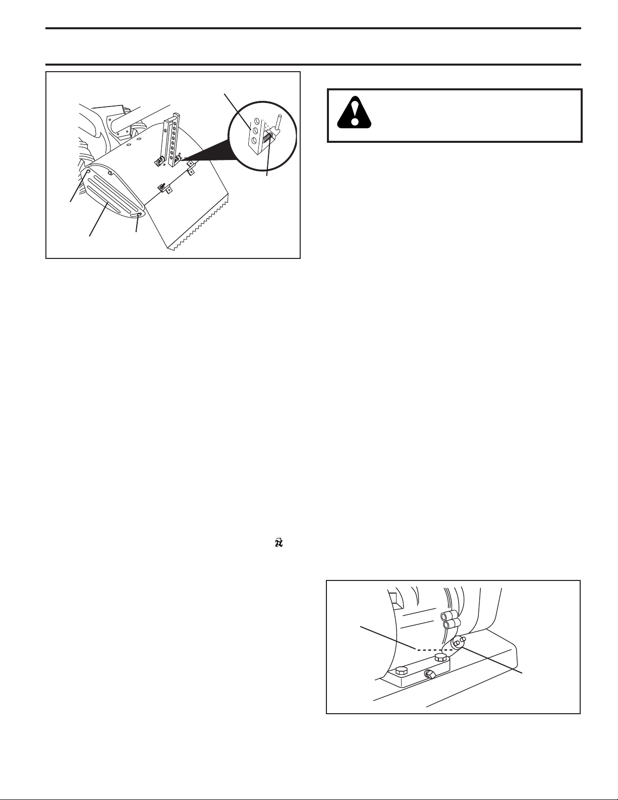
TILLING (See Fig. 12)
• Release depth stake pin. Pull the depth stake up for
increased tilling depth. Place depth stake pin in hole
of depth stake to lock in position.
• Place shift lever indicator in counter rotating ( ) till
position .
• Hold the drive control bar against the handle to start
tilling movement. Tines and wheels will both turn.
• Move throttle control to “FAST” position for deep tilling.
To cultivate, throttle control can be set at any desired
speed, depending on how fast or slow you wish to
cultivate.
IMPORTANT: ALWAYS RELEASE DRIVE CONTROL
BAR BEFORE MOVING SHIFT LEVER INTO ANOTHER
POSITION.
8
depth_stake_11
OPERATION
engine_art_4
DEPTH STAKE PIN
“RELEASED” POSITION
“LOCKED”
POSITION
NUT “B”
OUTER
SIDE SHIELD
NUT “A”
Fig. 12
TURNING
• Release the drive control bar.
• Move throttle control to “SLOW” position.
• Place shift lever indicator in “F” (forward) position. Tines
will not turn.
• Lift handle to raise tines out of ground.
• Swing the handle in the opposite direction you wish
to turn, being careful to keep feet and legs away from
tines.
• When you have completed your turn-around, release
the drive control bar and lower handle. Place shift lever in (till) position and move throttle control to de sired
speed. To begin tilling, hold drive control bar against
the handle.
CULTIVATING
• Use the forward rotating tine drive when cultivating,
tilling soft ground or tilling pre-tilled soil.
• Release depth and drag stake pins. Lower drag stake.
Pull the depth stake up for increased tilling depth. Place
proper pin in hole of depth stake or drag stake to lock
in position.
• Place shift lever indicator in forward rotating ( ) till
position.
• Hold the drive control bar against the handle to start
tilling movement. Tines and wheels will both turn.
• Move throttle control "FAST" position for deep tilling.
To cultivate, throttle control can be set at any desired
speed, depending on how fast or slow you wish to
cultivate.
• Always lower the drag stake when using the for ward
rotating tine drive.
TO TRANSPORT
CAUTION: Before lifting or trans port ing,
allow tiller engine and muffler to cool.
Disconnect spark plug wire. Drain
gasoline from fuel tank.
AROUND THE YARD
• Release the depth stake pin. Move the depth stake
down to the top hole for transporting the tiller. Place
depth stake pin in hole of depth stake to lock in position. This prevents tines from scuffing the ground.
• Place shift lever indicator in “F” (forward) position for
transporting.
• Hold the drive control bar against the handle to start
tiller movement. Tines will not turn.
• Move throttle control to desired speed.
AROUND TOWN
• Disconnect spark plug wire.
• Drain fuel tank.
• Transport in upright position to prevent oil leakage.
BEFORE START ING ENGINE
IMPORTANT: BE VERY CAREFUL NOT TO ALLOW DIRT
TO ENTER THE ENGINE WHEN CHECKING OR ADDING
OIL OR FUEL. USE CLEAN OIL AND FUEL AND STORE IN
APPROVED, CLEAN, COVERED CONTAINERS. USE CLEAN
FILL FUNNELS.
CHECK ENGINE OIL LEVEL (See Fig. 13)
• The engine in your unit has been shipped, from the
factory, already filled with SAE 30 summer weight oil.
• With engine level, clean area around oil filler plug and
remove plug.
• Engine oil should be to point of overflowing when engine
is level. For ap proxi mate capacity see “PROD UCT
SPEC I FI CA TIONS” on page 3 of this manual. All oil
must meet A.P.I. Service Classification SG-SL.
• Reinstall engine oil cap and tighten.
• For cold weather operation you should change oil for
easier starting (See oil viscosity chart in the Maintenance sec tion of this manual).
• To change engine oil, see the Maintenance section in
this manual.
OIL
LEVEL
OUTER SIDE SHIELDS (See Fig. 12)
The back edges of the outer side shields are slotted so
that the shields can be raised for deep tilling and low ered
for shal low tilling to protect small plants from being buried.
Loosen nut “A” in slot and nut “B”. Move shield to desired
position (both sides). Retighten nuts.
OIL
FILLER
PLUG
Fig. 13
9
 Loading...