

Husqvarna YTH22V46, 96045004500 User Manual

585 76 54-27
Repair Parts Manual
Manual De Repuestos
YTH22V46/96045004500
Please read the operator's manual carefully and make sure
you understand the instructions before using the machine.
Por favor lea cuidadosamente y comprenda
estas intrucciones antes de usar esta maquina.
English/Spanish

HOW TO USE THIS MANUAL
This manual is designed to provide the customer with a means to identify the parts on his/her tractor when ordering repair parts. The
illustrations may or may not represent the actual assemblies; therefore, it is not recommended to use this manual as a guide to assemble
or disassemble the tractor. Some hardware and parts are drawn larger in order to more readily identify them.
Each tractor has its own model number.
The model number for your tractor can be found on the fender under the seat.
When ordering parts, always give the following information:
• Product - “TRACTOR”
• MODEL NUMBER - “YTH22V46" (96045004500)”
• Part Number
• Part Description
TABLE OF CONTENTS
SCHEMATIC .......................................................................................................................................................................3
ELECTRICAL .................................................................................................................................................................. 4-5
CHASSIS ........................................................................................................................................................................ 6-7
DRIVE.............................................................................................................................................................................. 8-9
ENGINE ....................................................................................................................................................................... 10-11
STEERING .................................................................................................................................................................. 12-13
MOWER DECK ........................................................................................................................................................... 14-15
MOWER LIFT ....................................................................................................................................................................16
SEAT .................................................................................................................................................................................17
DECALS ............................................................................................................................................................................18
COMO UTILIZAR ESTE MANUAL
Este manual está diseñado para brindarle al comprador un medio para identificar las piezas del tractor para cuando necesite hacer el
pedido de un repuesto. Las ilustraciones pueden o no representar los ensambles reales; por lo tanto, no se recomienda utilizar este
manual como una guía para ensamblar o desarmar el tractor. Algunos accesorios y piezas están dibujados en tamaños más grandes
para identificarlos con mayor facilidad.
Cada tractor tiene su propio número de modelo.
El número de modelo del tractor se encuentra en el guardabarros debajo del asiento.
Cuando haga el pedido de una pieza, siempre brinde la siguiente información:
• Producto: ”TRACTOR”
• NÚMERO DE MODELO: “YTH22V46"(96045004500)”
• Número de pieza
• Descripción de la pieza
ÍNDICE
DIAGRAMA .......................................................................................................................................................................19
DIAGRAMA ELÉCTRICO ........................................................................................................................................... 20-21
CHASIS ....................................................................................................................................................................... 22-23
TRANSMISIÓN ........................................................................................................................................................... 24-25
MOTOR ....................................................................................................................................................................... 26-27
DIRECCIÓN ................................................................................................................................................................ 28-29
PLATAFORMA DE LA CORTADORA DE CÉSPED .................................................................................................. 30-31
ELEVACIÓN DE LA CORTADORA DE CÉSPED ............................................................................................................32
ASIENTO ...........................................................................................................................................................................33
CALCOMANÍAS ................................................................................................................................................................34
2
TRACTOR - MODEL NO. YTH22V46 (96045004500), PRODUCT NO. 960 45 00-45
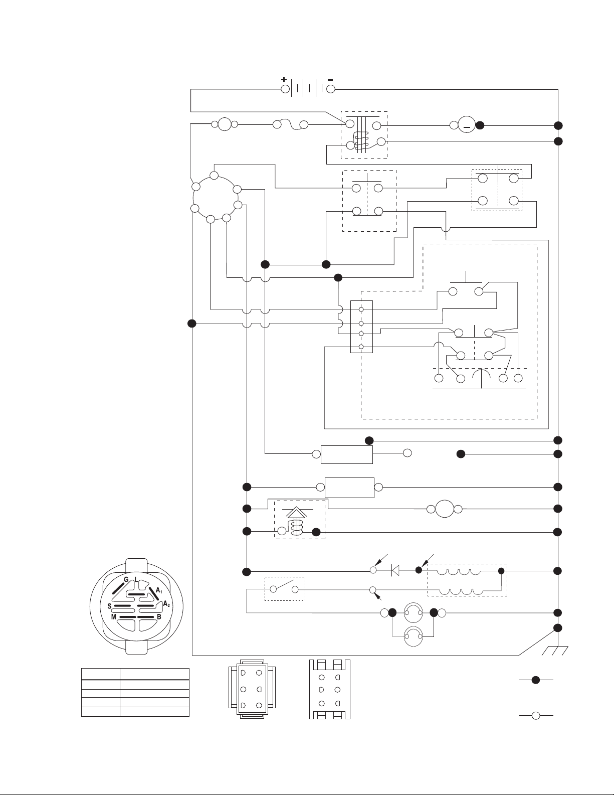
SCHEMATIC
SCH11
RED
(OPTIONAL)
B
G
L
A
AMMETER
S
M
A1
A2
WHITE
FUSE
BATTERY
BLACK
BLACK
BLACK
SOLENOID
DER
CLUTCH/BRAKE
(PEDAL UP)
WHITE
2
3
1
6
JUNCTION
CONNECTOR
BLACK
BLACK
BLACK
BLACKBLACK
GRAY
BLACK
STARTER
M
M
ATTACHMENT CLUTCH
(CLUTCH OFF)
BLACK
GRAY
REVERSE SWITCH
(NOT IN REVERSE)
SEAT SWITCH
(NOT OCCUPIED)
NOTE
YOUR TRACTOR IS
EQUIPPED WITH A SPECIAL
ALTERNATOR SYSTEM.
THE LIGHTS ARE NOT
CONNECTED TO THE
BATTERY, BUT HAVE THEIR
OWN ELECTRICAL SOURCE.
BECAUSE OF THIS, THE
BRIGHTNESS OF THE LIGHTS
WILL CHANGE WITH ENGINE
SPEED. AT IDLE THE LIGHTS
WILL DIM. AS THE ENGINE IS
SPEEDED UP, THE LIGHTS
WILL BECOME THEIR
BRIGHTEST.
IGNITION SWITCH
POSITION
RUN/OVERRIDE
OFF
CIRCUIT
M+G+A1
B+A1
B+A1RUN
B+S+A1START
“MAKE”
L+A2
BLACK
CHASSIS HARNESS
BLUE
63
52
41
CONNECTOR
(MATING SIDE)
BLACK /WHITE
BLUE
FUEL
LINE
FUEL SHUT-OFF
SOLENOID
(IF SO EQUIPPED)
RED
LIGHT SWITCH
DASH HARNESS
CONNECTOR
(MATING SIDE)
CHASSIS
HARNESS
IGNITION
UNIT
(OPTIONAL)
HOUR
METER
CHARGING SYSTEM OUTPUT
3 AMP DC @ 3600 RPM
LIGHTING SYSTEM OUTPUT
5 AMP AC @ 3600 RPM
ORANGE
BROWN
6
3
2
5
1
4
WIRING INSULATED CLIPS
NOTE: IF WIRING INSULATED
CLIPS WERE REMOVED FOR
SERVICING OF UNIT, THEY
SHOULD BE RE-INSTALLED TO
PROPERLY SECURE YOUR
WIRING.
SHORTING
CONNECTOR
SPARK
PLUGS GAP
(2 PLUGS ON
TWIN CYL. ENGINES)
BLACK
12V
POWER OUTLET
(OPTIONAL)
28 VOLTS AC MIN. @ 3600 RPM
(CHARGING SYSTEM DISCONNECTED)
DIODE
14 VOLTS AC MIN. @ 3600 RPM (LIGHTS OFF)
HEADLIGHTS
ALTERNATOR
BLACK
NON-REMOVABLE
CONNECTIONS
REMOVABLE
CONNECTIONS
3
TRACTOR - MODEL NO. YTH22V46 (96045004500), PRODUCT NO. 960 45 00-45
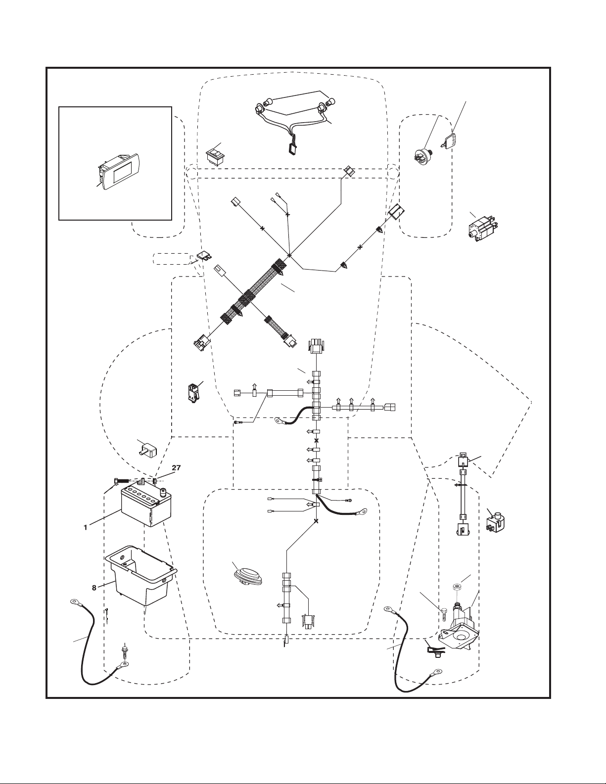
ELECTRICAL
TR02S
With Service Minder Option
4646
26
34
79
22
21
40
33
30
87
28
16
90
2
29
71
102
105
27
43
55
99
106
25
4

TRACTOR - MODEL NO. YTH22V46 (96045004500), PRODUCT NO. 960 45 00-45
ELECTRICAL
KEY PART
NO. NO. DESCRIPTION
1 532 16 34-65 Battery
2 874 76 04-12 Bolt Hex Head 1/4-20 x 3/4
8 532 19 32-28 Box Battery
16 532 17 61-38 Switch Interlock Push-In
21 532 40 02-52 Harness Socket Light w/4152J
22 532 00 41-52 Bulb Light
25 581 49 80-01 Cable Starter
26 532 17 51-58 Fuse
27 873 51 04-00 Nut Keps Hex 1/4-20 unc
28 532 42 16-86 Cable, Ground
29 532 40 15-45 Switch, Seat
30 532 19 33-50 Switch, Ign
33 532 41 19-33 Key/Chain
34 532 11 07-12 Switch Light/Reset
40 581 02 31-01 Harness Ign. Dash
43 532 19 25-07 Solenoid
46 532 40 17-63 Gauge Serviceminder Hrmtr
55 817 06 05-12 Screw Thdrol 5/16-18 x 3/4 TYTT
71 581 02 30-01 Harness Ign. Chassis
79 532 17 52-42 Socket Asm. Bulb
87 532 19 78-02 Switch Interlock
90 532 43 53-95 Cover Terminal
99 817 67 04-12 Screw Hexwsh
102 532 40 44-54 Harness Pigtail
105 532 40 75-68 Switch Reverse
106 532 17 48-14 Pal Nut 1/4 Lugs
NOTE: All component dimensions given in U.S. inches
1 inch = 25.4 mm
5
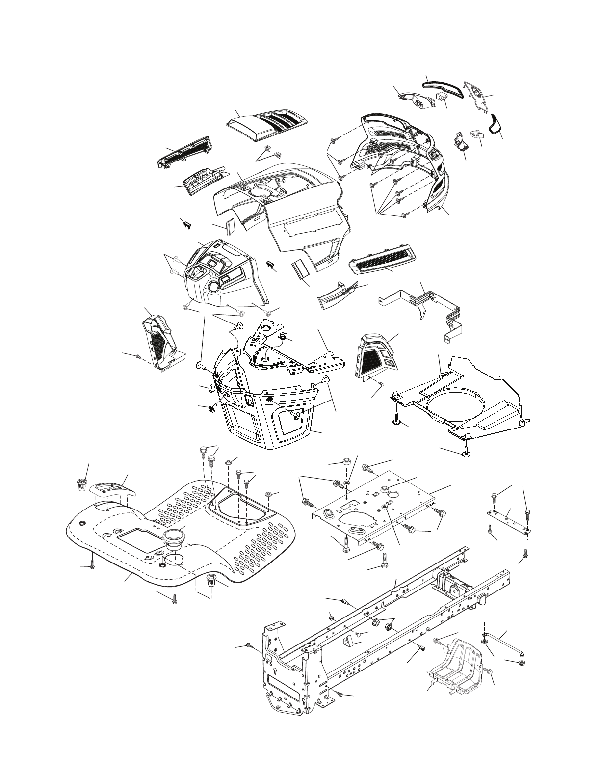
TRACTOR - MODEL NO. YTH22V46 (96045004500), PRODUCT NO. 960 45 00-45
CHASSIS
15
208
3
204
297
181
350
196
336
203
176
206
137
195
176
5
234
176
36
14
214
194
36
137
176
194
68
177
234
175
130
235
182
176
130
236
130
350
205
202
335
68
130
151
235
130
150
18
34
25
191
207
213
218
287
37
162
chassis-tex_GT HUSQ_II_121_r1
138
159
181
183
228
306
68
183
159
236
180
194
146
125
228
152
68
159
68
68
217
52
159
6

TRACTOR - MODEL NO. YTH22V46 (96045004500), PRODUCT NO. 960 45 00-45
CHASSIS
KEY PART
NO. NO. DESCRIPTION
3 532 44 44-81 Applique Sub Asm.
5 581 46 69-04 Dash
14 532 44 11-77 Hood
15 532 43 97-33 Lens LH
18 532 44 06-53 Grille
25 532 44 33-85 Lens RH
34 580 91 08-01 Plate Engine
36 817 06 05-12 Screw 5/16-18 x 3/4
37 532 44 12-06 Fender
52 873 68 05-00 Nut Lock 5/16-18
68 817 49 05-08 Screw Thdrol 5/16-18 x 1/2
125 581 68 48-01 Clip Fuel Line
130 532 41 63-58 Screw #10 x 0.750
137 532 40 75-90 Bumper Dash
138 532 43 97-47 Cupholder
146 581 85 79-01 Bolt
150 532 43 97-74 Air Duct
151 532 43 66-70 Bracket Pivot
152 532 43 98-70 Shield Browning
159 817 00 06-12 Screw Hexwsh Thrd 3/8-16 x 3/4
162 532 14 24-32 Screw
175 532 19 63-04 Crossmember
176 532 40 07-76 Screw 10-24 x 5/8
177 532 19 52-27 Bushing Steering
180 532 19 54-57 Chassis
181 532 43 97-46 Bushing Mtg. Fender Crgo
182 532 40 68-59 Dash Lower
183 874 52 05-20 Bolt 5/16-18 x 1-1/4
191 532 43 74-55 Insert Reflective RH
KEY PART
NO. NO. DESCRIPTION
194 873 90 05-00 Nut Lock Hex Flange 5/16-18
195 532 40 41-37 Plug Hole Dash Lower
196 532 43 96-47 Console Asm. Deck Lift
202 532 43 97-28 Vent Side Hood RH
203 532 43 97-27 Vent Side Hood LH
204 532 43 57-14 Vent Top Hood
205 532 43 97-30 Skirt Hood Side RH
206 532 43 97-29 Skirt Hood Side LH
207 532 43 97-34 Bezel RH
208 532 43 97-35 Bezel LH
213 874 76 05-12 Bolt 5/16-18 x 3/4
214 532 19 91-45 Clip Retainer Tinner
217 532 40 91-67 Rod Pivot
218 532 19 63-95 X-Piece Hood Stop
228 532 19 51-61 Stud Fastner
234 532 40 47-42 Bumper Hood
235 532 40 61-29 Spacer Fender
236 873 93 05-00 Nut Lock 5/16-18 unc
287 817 60 04-06 Screw 1/4-20 x 3/8
297 532 43 74-56 Insert Reflective LH
306 873 90 06-00 Nut Lock
335 532 44 82-04 Cover RH
336 532 44 53-09 Cover LH
350 532 44 51-43 Clip X-mas Tree
NOTE: All component dimensions given in U.S. inches
1 inch = 25.4 mm
7
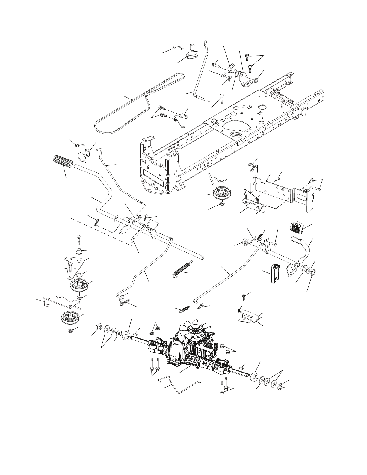
TRACTOR - MODEL NO. YTH22V46 (96045004500), PRODUCT NO. 960 45 00-45
DRIVE
207
206
125
116
26
56
221
92
213
160
209
190
49
221
42
64
159
185
186
189
187
51
52
51
33
drive-tex_K46_pedal_88_r2
184
50
205
230
35
167
15
183
188
159
2
143
73
29
116
160
99
17
216
1
161
52
51
171
163
153
170
211
226
73
227
116
153
2
230
215
125
125
183
208
225
80
125
125
125
214
210
222
211
166
205
33
8

TRACTOR - MODEL NO. YTH22V46 (96045004500), PRODUCT NO. 960 45 00-45
DRIVE
KEY PART
NO. NO. DESCRIPTION
1 – – – – – – Transaxle, TUFFTORQ K46BT
(426120) (Order parts from trans-
axle manufacturer.)
2 532 12 35-83 Key Square
15 819 13 13-16 Washer 13/32 x 13/16 x 16 Ga.
17 532 41 36-78 Spring, Brake
26 532 19 96-79 Spring Return Cruise
29 532 40 38-06 Rod, Brake
33 812 00 00-01 Ring E
35 583 86 45-01 Rod, Brake, Park
42 532 12 48-72 Cover, Foot Pedal
49 872 11 06-14 Bolt
50 532 19 43-27 Pulley Idler Flat
51 873 90 06-00 Lock Nut 3/8-16
52 532 19 43-26 Idler V-Groove Offset
56 532 13 09-69 V-Belt, Drive
64 532 19 78-65 Shaft Asm. Pedal Brake Control
73 874 49 05-40 Bolt Hex 5/16-18 x 2 1/2 G.5
80 532 44 06-19 Strap Torque
92 874 76 05-20 Bolt Fin Hex 5/16-18 unc x 1.25
99 532 41 57-42 Rod Spring Bypass
116 873 90 05-00 Nut Lock Hex Flange 5/16-18
125 817 00 05-12 Screw 5/16-18 x 3/4
143 817 49 05-08 Screw 5/16-18 x 1/2
153 532 12 47-88 Retainer Spring 1"
159 876 02 04-12 Pin Cotter 1/8 x 3/4
160 532 16 94-84 Retainer Clip
161 532 10 57-09 Spring, Return, Clutch
163 532 44 82-75 Rod Control
166 532 42 91-64 Nut Push
167 532 40 52-57 Latch Brake Parking
KEY PART
NO. NO. DESCRIPTION
170 532 19 43-22 Keeper V-Idler
171 872 11 06-16 Bolt 3/8-16 unc x 2
183 532 13 70-57 Spacer Axle
184 532 44 14-55 Handle Parking Brake
185 872 11 06-22 Bolt
186 532 19 43-21 Spacer Retainer
187 819 13 32-10 Washer
188 532 19 43-23 Link Clutch Ground Drive
189 532 19 43-17 Bellcrank Ground Drive
190 532 19 43-18 Keeper Bellcrank Ground Drive
205 532 12 17-48 Washer 25/32 x 1-5/8 x 16 Ga.
206 532 44 85-96 Bracket Mount Latch Cruise
207 532 19 78-68 Latch Control Cruise
208 532 19 78-69 Gear Sector Control Cruise
209 532 19 95-92 Rod Control Cruise
210 532 40 09-80 Rocker Asm. Pedal Control
211 532 12 01-83 Bearing Nylon
213 532 40 31-19 Knob Control Cruise
214 532 42 12-63 Pedal Forward
215 532 40 17-23 Pedal Reverse
216 532 19 61-31 Bracket Pulley Idler
221 532 40 31-87 Retainer Spring Clip Handle
222 879 21 20-10 Washer 21/32 x 1-1/4 10 Ga.
225 532 40 33-19 Keeper Belt Transaxle
226 532 40 15-64 Bracket Strap Torque
227 817 49 05-12 Screw 5/16-18 x 3/4
230 532 18 89-67 Washer .793 x 1.637 x 060
NOTE: All component dimensions given in U.S. inches
1 inch = 25.4 mm
9
TRACTOR - MODEL NO. YTH22V46 (96045004500), PRODUCT NO. 960 45 00-45
ENGINE
15
18
21
37
20
97
96
28
37
90
1
69
87
62
45
84
84
71
70
12
111
82
81
42
85
79
2
9
29
engine-tex_bs-2cyl_71
SPARK ARRESTER KIT
10

TRACTOR - MODEL NO. YTH22V46 (96045004500), PRODUCT NO. 960 45 00-45
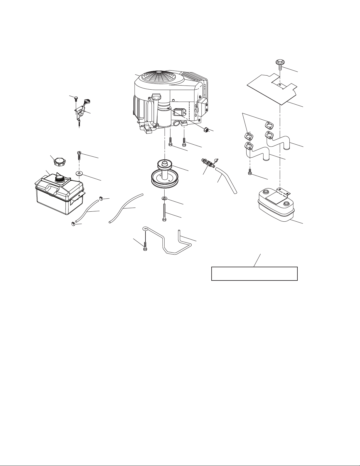
ENGINE
KEY PART
NO. NO. DESCRIPTION
1 – – – – – – Engine B&S Model No.44R677-0004-G1
(585700401)(Order parts from engine
manufacturer.)
2 532 44 59-62 Muffler
9 584 90 80-01 Keeper Belt Engine
12 532 40 54-72 Pulley Engine
15 532 43 30-07 Tank Fuel
18 581 17 61-01 Cap Fuel
20 532 17 83-85 Control Throttle/Choke
21 532 41 63-58 Screw #10 x 0.750 BOS Thread
28 532 40 11-37 Fuel Line
29 532 13 71-80 Spark Arrester Kit
37 532 12 34-87 Clamp Hose
42 810 04 07-00 Washer Lock 7/16
45 873 51 04-00 Nut Keps Hex 1/4-20 unc
62 532 43 40-17 Shield Heat Muffler
69 532 16 53-91 Gasket
70 581 88 11-01 Exhaust Tube LH
71 581 88 10-01 Exhaust Tube RH
79 532 18 39-06 Screw Socket HD 5/16-18 x 1
81 532 14 84-56 Tube Drain Oil Easy
82 532 42 82-87 Valve Drain Oil
84 817 06 06-20 Screw 3/8-16 x 1-1/4
85 532 17 39-37 Bolt 7/16-20 x 4 x Gr. 5-1.5
87 532 17 18-77 Bolt 5/16-18 unc x 3/4
90 817 00 06-16 Screw 3/8-16 x 1
96 819 09 14-16 Washer 9/32 x 7/8 x 16
97 817 67 04-12 Screw 1/4-20 x 3/4
111 532 41 41-19 Purge Line
NOTE: All component dimensions given in U.S. inches
1 inch = 25.4 mm
For engine service and replacement parts, call the toll free
number for your engine manufacturer listed below:
Briggs & Stratton 1-800-233-3723
Engine Power Rating Information
The gross power rating for individual gas engine models is labeled in accordance with SAE (Society of Automotive Engineers) code J1940 (Small Engine Power & Torque Rating Procedure), and rating performance has been obtained and
corrected in accordance with SAE J1995 (Revision 2002-05). Torque values are derived at 3060 RPM; horsepower values
are derived at 3600 RPM. Actual gross engine power will be lower and is affected by, among other things, ambient operating conditions and engine-to-engine variability. Given both the wide array of products on which engines are placed and
the variety of environmental issues applicable to operating the equipment, the gas engine will not develop the rated gross
power when used in a given piece of power equipment (actual “on-site” or net power). This difference is due to a variety
of factors including, but not limited to, accessories (air cleaner, exhaust, charging, cooling, carburetor, fuel pump, etc.),
application limitations, ambient operating conditions (temperature, humidity, altitude), and engine-to-engine variability.
Due to manufacturing and capacity limitations, Briggs & Stratton may substitute an engine of higher rated power for this
Series engine.
11
 Loading...