

Husqvarna 954140010H User Manual

YTH180
Owner’s Manual

SAFETY RULES
Safe Operation Practices for Ride-On Mowers
IMPORTANT: THIS CUTTING MACHINE IS CAPABLE OF AMPUTATING HANDS AND FEET AND THROWING OBJECTS.
FAILURE TO OBSERVE THE FOLLOWING SAFETY INSTRUCTIONS COULD RESULT IN SERIOUS INJURY OR DEATH.
I. GENERAL OPERATION
• Read, understand, and follow all instructions in the manual
and on the machine before starting.
• Only allow responsible adults, who are familiar with the
instructions, to operate the machine.
• Clear the area of objects such as rocks, toys, wire, etc.,
which could be picked up and thrown by the blade.
• Be sure the area is clear of other people before mowing. Stop
machine if anyone enters the area.
• Never carry passengers.
• Do not mow in reverse unless absolutely necessary. Always
look down and behind before and while backing.
• Be aware of the mower discharge direction and do not point
it at anyone. Do not operate the mower without either the
entire grass catcher or the guard in place.
• Slow down before turning.
• Never leave a running machine unattended. Always turn off
blades, set parking brake, stop engine, and remove keys
before dismounting.
• Turn off blades when not mowing.
• Stop engine before removing grass catcher or unclogging
chute.
• Mow only in daylight or good artificial light.
• Do not operate the machine while under the influence of
alcohol or drugs.
• Watch for traffic when operating near or crossing roadways.
• Use extra care when loading or unloading the machine into
a trailer or truck.
II. SLOPE OPERATION
Slopes are a major factor related to loss-of-control and
tipover accidents, which can result in severe injury or death.
All slopes require extra caution. If you cannot back up the
slope or if you feel uneasy on it, do not mow it.
DO:
• Mow up and down slopes, not across.
• Remove obstacles such as rocks, tree limbs, etc.
• Watch for holes, ruts, or bumps. Uneven terrain could
overturn the machine.
• Use slow speed. Choose a low gear so that you will not have
to stop or shift while on the slope.
• Follow the manufacturer’s recommendations for wheel
weights or counterweights to improve stability.
• Use extra care with grass catchers or other attachments.
These can change the stability of the machine.
• Keep all movement on the slopes
make sudden changes in speed or direction.
• Avoid starting or stopping on a slope. If tires lose traction,
disengage the blades and proceed slowly
slope.
DO NOT:
•
Do not
turn on slopes unless necessary, and then, turn slowly
and gradually downhill, if possible.
Do not
•
•
•
•
mow near drop-offs, ditches, or embankments. The
mower could suddenly turn over if a wheel is over the edge
of a cliff or ditch, or if an edge caves in.
Do not
mow on wet grass. Reduced traction could cause
sliding.
Do not
try to stabilize the machine by putting your foot on the
ground.
Do not
use grass catcher on steep slopes.
Tall grass can hide obstacles.
slow
and
gradual
. Do not
straight
down the
III. CHILDREN
Tragic accidents can occur if the operator is not alert to the
presence of children. Children are often attracted to the
machine and the mowing activity.
Never
assume that
children will remain where you last saw them.
• Keep children out of the mowing area and under the watchful
care of another responsible adult.
• Be alert and turn machine off if children enter the area.
• Before and when backing, look behind and
children.
• Never carry children. They may fall off and be seriously
injured or interfere with safe machine operation.
• Never allow children to operate the machine.
• Use extra care when approaching blind corners, shrubs,
trees, or other objects that may obscure vision.
down
IV. SERVICE
• Use extra care in handling gasoline and other fuels. They are
flammable and vapors are explosive.
- Use only an approved container.
- Never remove gas cap or add fuel with the engine
running. Allow engine to cool before refueling. Do not
smoke.
- Never refuel the machine indoors.
- Never store the machine or fuel container inside where
there is an open flame, such as a water heater.
• Never run a machine inside a closed area.
• Keep nuts and bolts, especially blade attachment bolts, tight
and keep equipment in good condition.
• Never tamper with safety devices. Check their proper
operation regularly.
• Keep machine free of grass, leaves, or other debris build-up.
Clean oil or fuel spillage. Allow machine to cool before
storing.
• Stop and inspect the equipment if you strike an object.
Repair, if necessary, before restarting.
• Never make adjustments or repairs with the engine running.
• Grass catcher components are subject to wear, damage, and
deterioration, which could expose moving parts or allow
objects to be thrown. Frequently check components and
replace with manufacturer's recommended parts, when necessary.
• Mower blades are sharp and can cut. Wrap the blade(s) or
wear gloves, and use extra caution when servicing them.
• Check brake operation frequently. Adjust and service as
required.
Look for this symbol to point out important safety precautions. It means
CAUTION!!! BECOME ALERT!!! YOUR
SAFETY IS INVOLVED.
CAUTION: Always disconnect spark plug
wire and place wire where it cannot contact
spark plug in order to prevent accidental
starting when setting up, transporting,
adjusting or making repairs.
WARNING
The engine exhaust from this product contains chemicals known to the State of California to cause cancer, birth defects, or other
reproductive harm.
2
for small

CONGRATULATIONS on your purchase of a new tractor.
It has been designed, engineered and manufactured to
give you the best possible dependability and performance.
Should you experience any problem you cannot easily
remedy, please contact your nearest authorized service
center/department. We have competent, well-trained technicians and the proper tools to service or repair this unit.
Please read and retain this manual. The instructions will
enable you to assemble and maintain your unit properly.
Always observe the “SAFETY RULES”.
MODEL
NUMBER YTH180
SERIAL
NUMBER ____________________________________
DATE OF PURCHASE __________________________
THE MODEL AND SERIAL NUMBERS WILL BE FOUND
ON A PLATE UNDER THE SEAT.
YOU SHOULD RECORD BOTH SERIAL NUMBER AND
DATE OF PURCHASE AND KEEP IN A SAFE PLACE
FOR FUTURE REFERENCE.
PRODUCT SPECIFICATIONS
HORSEPOWER: 18.0
GASOLINE CAPACITY 3.5 GALLONS
AND TYPE: UNLEADED REGULAR
OIL TYPE (API-SF/SG/SH): SAE 10W30 (above 32°F)
SAE 5W-30 (below 32°F)
OIL CAPACITY: W/ FILTER: 4.2 PINTS
W/O FILTER: 3.7 PINTS
SPARK PLUG: CHAMPION RC12YC
(GAP: .030")
VALVE CLEARANCE: NOT ADJUSTABLE
GROUND SPEED (MPH): FORWARD: 5.5
REVERSE: 2.4
TIRE PRESSURE: FRONT: 14 PSI
REAR: 10 PSI
CHARGING SYSTEM: 15 AMPS @ 3600 RPM
BATTERY: AMP/HR: 35
MIN. CCA: 280
CASE SIZE: U1R
BLADE BOLT TORQUE: 27-35 FT. LBS.
CUSTOMER RESPONSIBILITIES
• Read and observe the safety rules.
• Follow a regular schedule in maintaining, caring for and
using your tractor.
• Follow the instructions under “Customer Responsibilities” and “Storage” sections of this owner’s manual.
WARNING: This tractor is equipped with an internal
combustion engine and should not be used on or near any
unimproved forest-covered, brush-covered or grass-covered land unless the engine’s exhaust system is equipped
with a spark arrester meeting applicable local or state laws
(if any). If a spark arrester is used, it should be maintained
in effective working order by the operator.
A spark arrester for the muffler is available through your
nearest authorized service center/department (See REPAIR PARTS section of this manual).
3

TABLE OF CONTENTS
SAFETY RULES............................................................2
PRODUCT SPECIFICATIONS ......................................3
CUSTOMER RESPONSIBILITIES .....................3, 16-19
ASSEMBLY ................................................................6-9
OPERATION........................................................... 10-15
MAINTENANCE SCHEDULE......................................16
SERVICE AND ADJUSTMENTS............................20-25
STORAGE ................................................................... 26
TROUBLESHOOTING............................................27-28
REPAIR PARTS -1 TRACTOR...............................29-45
WARRANTY ................................................................47
4
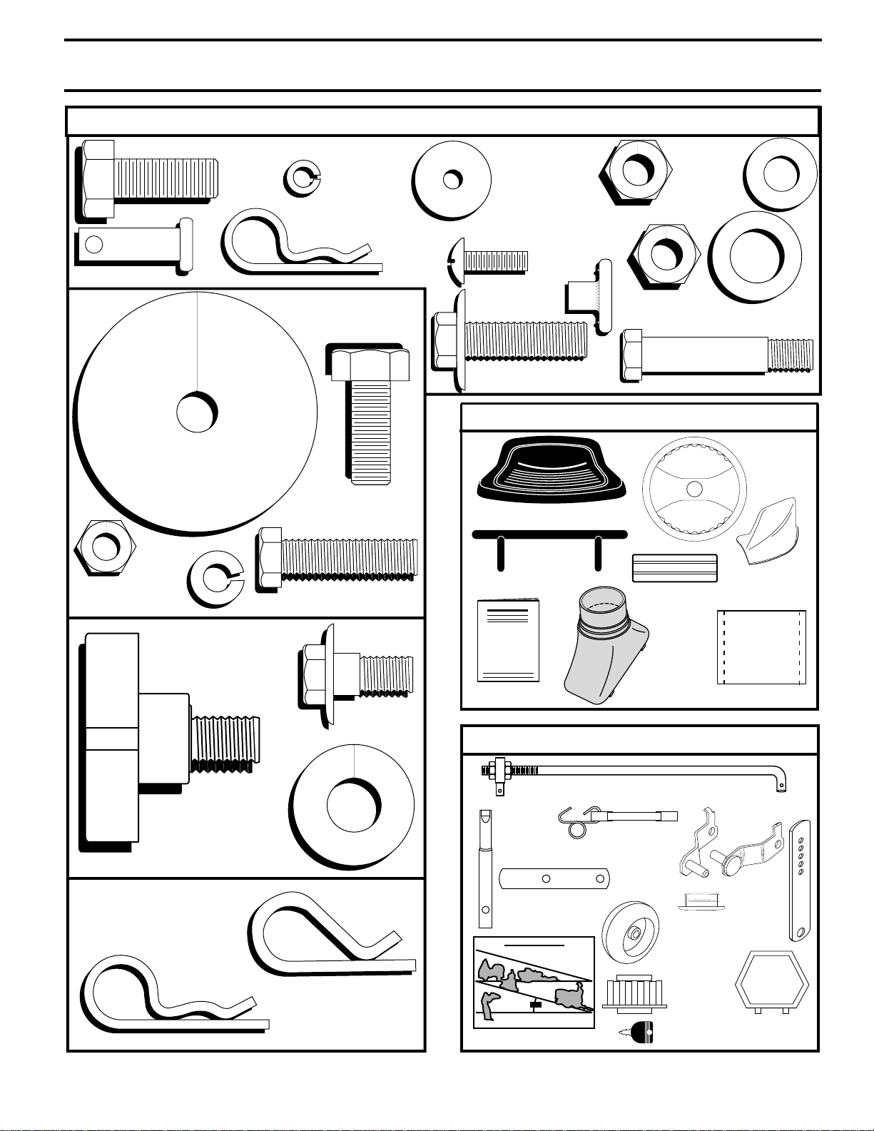
CONTENTS OF HARDWARE PACK
Parts Bag contents shown full size
(2) Hex Bolts 3/8-16 x 1
(2) Lock
washers
#10
(4) Retainer Springs
(double loop)
(2) Washers
3/16 x 3/4 x
16 Gauge
(2) Nylon
Locknuts 3/8-16
(2) Screws
#10 x 5/8
(4)
Washers
3/8 x 3/4
x 14 Ga.
(4) Clevis Pins
(1)
Locknut
5/16-18
(1) Lockwasher 3/8
(1) Large Flat
(1) Shoulder
Bolt 5/16-18
Washer
(1) Hex Bolt
3/8-16 x 1
(1) Hex Bolt
5/16-18 x 1-1/4
(2) Weld
Nuts #10
(4) Tapping Screws
3/8-16 x 1-1/4
(4)
Locknut
3/8-16
17/32 x 7/8 x 16 Ga.
(4) Shoulder Bolt
Parts packed separately in carton
Seat
Front
Bumper
Nose Roller
Steering
Manual
Sleeve
(2) Washers
Steering
Wheel
Mulcher
Plate
Parts Bag
(1) Knob
(1) Washer
17/32 x 1-3/16
x 12 Gauge
(3) Retainer Springs
(double loop)
(4) Retainer Springs
(single loop)
Parts bag contents not shown full size
Steering
Extension
Shaft
(2) Extension
Brackets
Slope Sheet
(2) Front Link Assemblies
(2) Latch Hook
Assemblies
(2) End
(4) Wheels
Steering
Wheel
Adapter
(2) Keys
Caps
Nose
Roller
Brackets
(4)
Adjusting
Bar
Steering
Wheel Insert
5
ASSEMBLY
Your new tractor has been assembled at the factory with exception of those parts left unassembled for shipping purposes.
To ensure safe and proper operation of your tractor all parts and hardware you assemble must be tightened securely. Use
the correct tools as necessary to insure proper tightness.
TOOLS REQUIRED FOR ASSEMBLY
A socket wrench set will make assembly easier. Standard
wrench sizes are listed.
Phillips Screwdriver
(2) 1/2" wrenches Tire pressure gauge
(2) 9/16" wrenches Utility knife
Pliers (1) 3/4" socket with drive ratchet
When right or left hand is mentioned in this manual, it
means when you are in the operating position (seated
behind the steering wheel).
TO REMOVE TRACTOR FROM CARTON
UNPACK CARTON
• Remove all accessible loose parts and parts cartons
from carton (See page 5).
• Cut, from top to bottom, along lines on all four corners
of carton, and lay panels flat.
• Remove mower and packing materials.
• Check for any additional loose parts or cartons and
remove.
BEFORE ROLLING TRACTOR OFF SKID
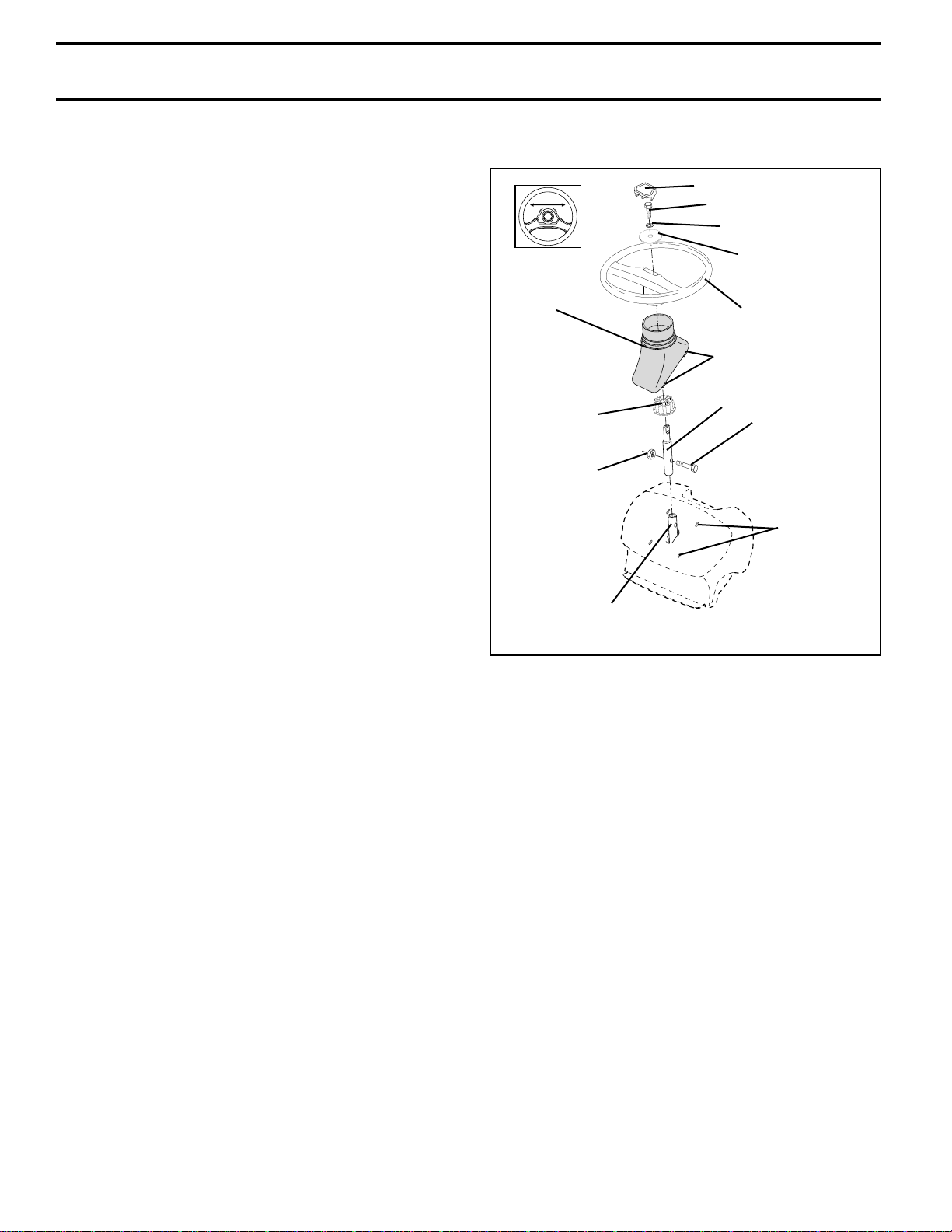
ATTACH STEERING WHEEL (See Fig. 1)
ASSEMBLE EXTENSION SHAFT AND BOOT
• Slide extension shaft onto lower steering shaft. Align
mounting holes in extension and lower shafts and
install 5/16 hex bolt and locknut. Tighten securely.
IMPORTANT: TIGHTEN BOLT AND NUT SECURELY TO
18-22 FT. LBS TORQUE.
• Place tabs of steering boot over tab slots in dash and
push down to secure.
INSTALL STEERING WHEEL
• Position front wheels of the tractor so they are pointing
straight forward.
• Slide steering wheel adapter onto steering shaft extension.
• Position steering wheel so cross bars are horizontal
(left to right) and slide inside boot and onto adapter.
• Assemble large flat washer, 3/8 lock washer, 3/8 hex
bolt and tighten securely.
• Snap steering wheel insert into center of steering
wheel.
• Remove protective materials from tractor hood and
grill.
IMPORTANT: CHECK FOR AND REMOVE ANY STAPLES
IN SKID THAT MAY PUNCTURE TIRES WHERE TRACTOR
IS TO ROLL OFF SKID.
STEERING WHEEL INSERT
3/8 HEX BOLT
3/8 LOCK WASHER
LARGE FLAT
WASHER
STEERING
BOOT
ADAPTER
5/16 LOCKNUT
LOWER
STEERING
SHAFT
STEERING
WHEEL
TAB
EXTENSION
SHAFT
5/16 HEX BOLT
TAB SLOTS
FIG. 1
TO ROLL TRACTOR OFF SKID (See Operation
section for location and function of controls)
• Press lift lever plunger and raise attachment lift lever to
its highest position.
• Release parking brake by depressing clutch/brake
pedal.
• Place freewheel control in freewheeling position to
disengage transmission (See “TO TRANSPORT” in
the Operation section of this manual).
• Roll tractor forward off skid.
6
ASSEMBLY
HOW TO SET UP YOUR TRACTOR
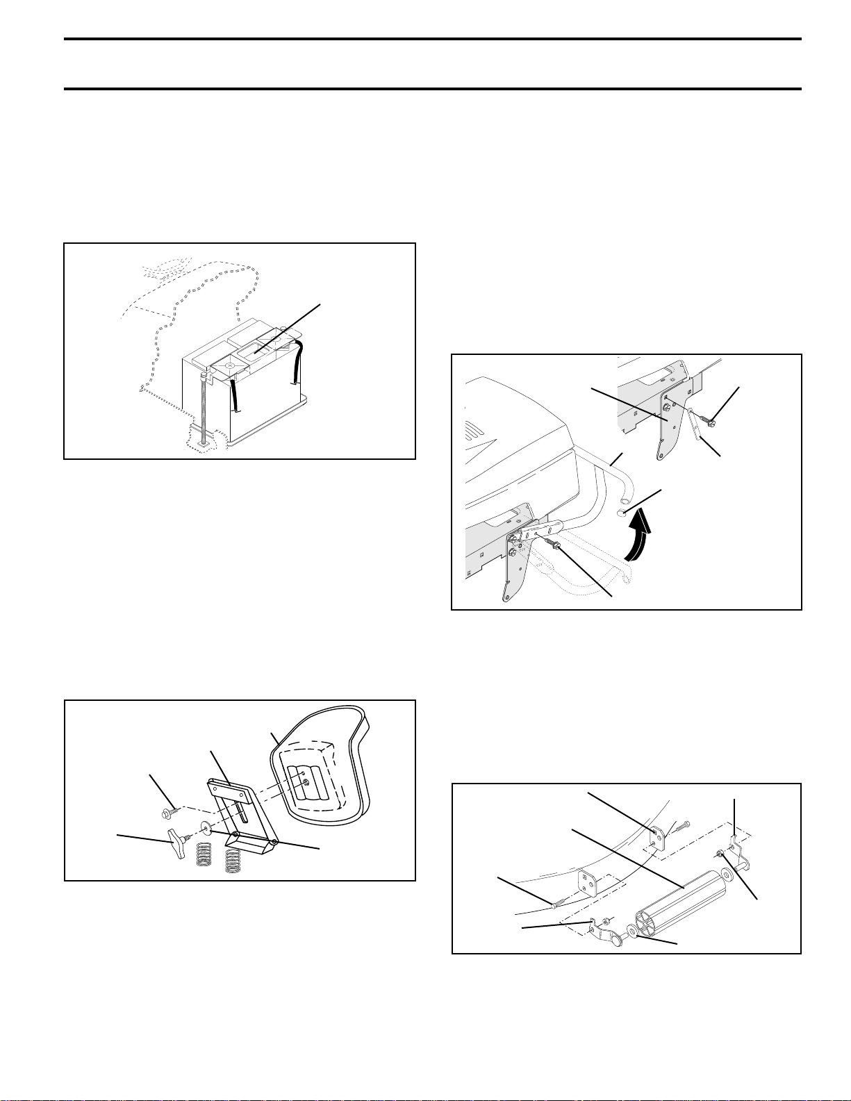
CHECK BATTERY (See Fig. 2)
• Lift hood to raised position.
• If this battery is put into service after month and year
indicated on label (label located between terminals)
charge battery for minimum of one hour at 6-10 amps.
(See "BATTERY" in MAINTENANCE section of this
manual for charging instructions).
LABEL
FIG. 2
TO ATTACH FRONT BUMPER (See Fig. 4)
NOTE: For ease of assembly, you may wish to obtain the
assistance of another person for mounting bumper to
tractor.
• Press or tap the end caps into ends of bumper tube.
• The existing top screw and the existing front screw
must be removed from both sides.
• On both sides of chassis, position extension bracket as
shown and loosely assemble to rear chassis hole with
supplied 3/8-16 x 1-1/4 screw. Do not tighten the
brackets. Allow them to hang from the chassis.
• Position bumper and extension brackets so brackets
can be slid inside flattened ends of bumper.
• Slide bumper onto brackets and pivot upwards to align
center holes in extension brackets and tractor chassis.
• With holes aligned, install additional screws.
• Tighten all four (4) screws securely.
FRONT
SUSPENSION
BRACKET
BUMPER
END CAP
TOP
SCREW
EXTENSION
BRACKET
INSTALL SEAT (See Fig. 3)
Adjust seat before tightening adjustment knob.
• Remove cardboard packing on seat pan.
• Place seat on seat pan and assemble shoulder bolt.
Tighten shoulder bolt securely.
• Assemble adjustment knob and flat washer loosely.
Do not tighten.
• Lower seat into operating position and sit on seat.
• Slide seat until a comfortable position is reached which
allows you to press clutch/brake pedal all the way
down.
• Get off seat without moving its adjusted position.
• Raise seat and tighten adjustment knob securely.
SEAT
SEAT PAN
SHOULDER
BOLT
ADJUSTMENT
KNOB
FLAT WASHER
FIG. 3
Slide Bumper onto
Extension Brackets
and Pivot Upwards
FRONT SCREW
FIG. 4
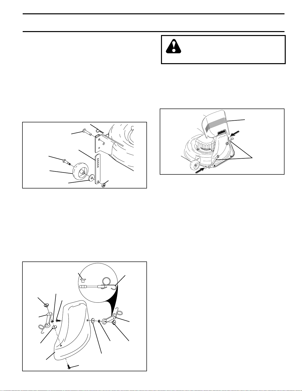
TO ATTACH NOSE ROLLER (See Fig. 5)
• Position brackets, 17/32 x 7/8 x 16 gauge washers, and
nose roller between deck mounting brackets as shown.
Be sure to position brackets on correct side, as shown.
• Install 3/8-16 x 1 hex bolts and 3/8-16 lock nuts as
shown. Tighten hardware securely.
NOTE: Be sure bracket tabs are positioned in tab holes in
deck brackets.
TAB HOLE
NOSE ROLLER
HEX
BOLT
“B”
BRACKET
TAB
FIG. 5
“A” BRACKET TAB
LOCK NUT
WASHER
7
ASSEMBLY
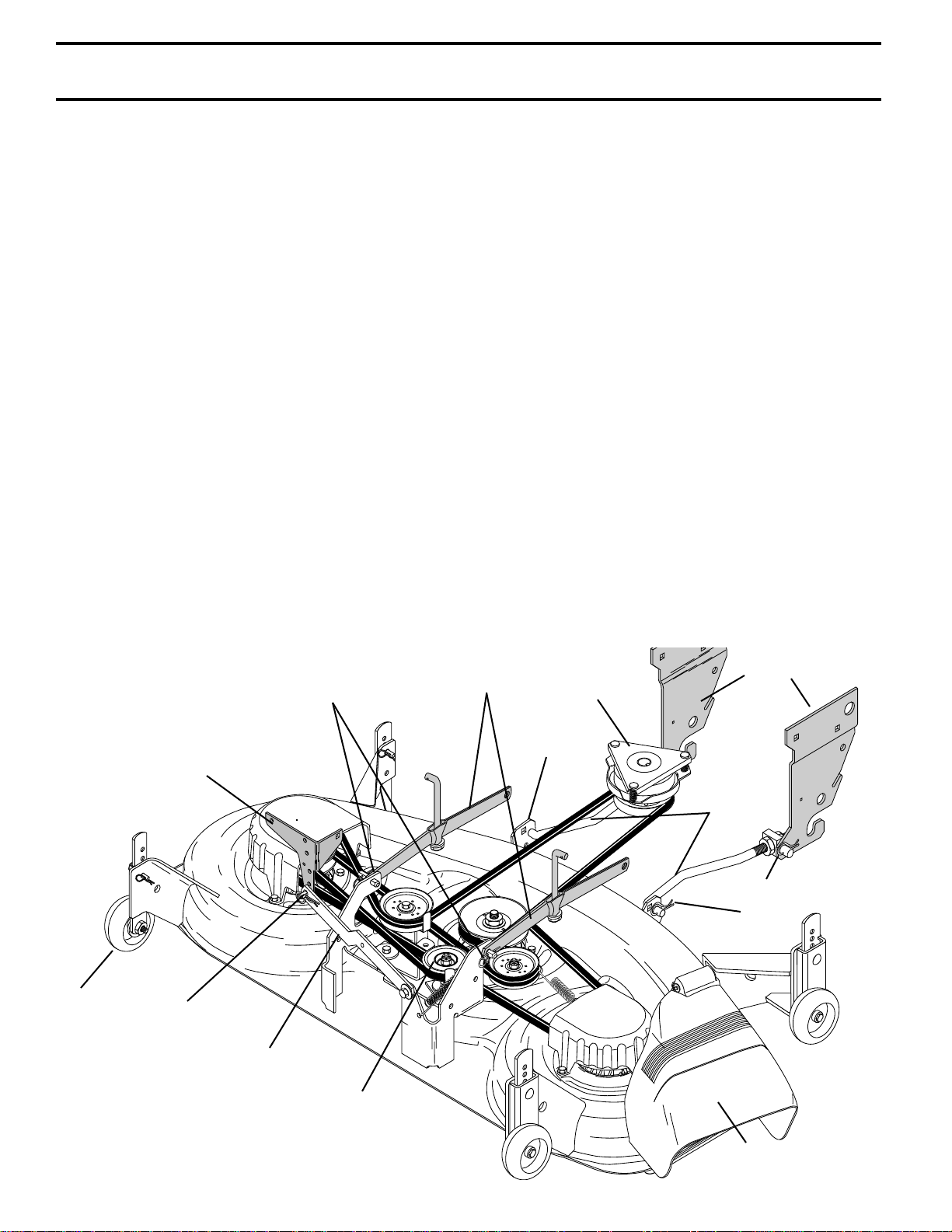
INSTALL MOWER AND DRIVE BELT (See
Figs. 6 and 9)
Be sure tractor is on level surface and mower suspension
arms are raised with attachment lift control. Engage parking brake.
• Cut and remove ties securing anti-sway bar and belts.
Swing anti-sway bar to left side of mower deck.
• Slide mower under tractor with discharge guard to right
side of tractor.
IMPORTANT: CHECK BELT FOR PROPER ROUTING IN
ALL MOWER PULLEY GROOVES. INSTALL BELT INTO
ELECTRIC CLUTCH PULLEY GROOVE.
• Install one front link in top hole of the R.H. front mower
bracket and R.H. front suspension bracket. Retain with
two single loop retainer springs as shown.
• Install second front link in L.H. front suspension bracket
only and retain with single loop retainer spring as
shown.
• Turn height adjustment knob counterclockwise until it
stops.
• Lower mower linkage with attachment lift control.
• Place the L.H. suspension arm on outward pointing
deck pin. If necessary, rock and raise front of mower
to align deck pin with the hole in suspension arm.
Retain with double loop retainer spring with loops down
as shown.
• Slide left side of mower back and install the unattached
front link in top hole of the L.H. front mower bracket.
Retain with single loop retainer spring as shown.
• Place the R.H. suspension arm on outward pointing
deck pin. If necessary, rock and raise front of mower
to align deck pin with the hole in suspension arm.
Retain with double loop retainer spring with loops down
as shown.
DOUBLE LOOP RETAINER
SPRING
pins)
CHASSIS
BRACKET
(Outward pointing deck
• Connect anti-sway bar to chassis bracket under left
• Turn height adjustment knob clockwise to remove
• Raise mower to highest position.
• Adjust gauge wheels before operating mower as shown
CHECK MOWER LEVELNESS
For best cutting results, mower should be properly leveled.
See “TO LEVEL MOWER HOUSING” in the Service and
Adjustments section of this manual.
CHECK FOR PROPER POSITION OF ALL
BELTS
See the figures that are shown for replacing motion, mower
drive, and mower blade drive belts in the Service and
Adjustments section of this manual. Verify that the belts
are routed correctly.
CHECK TIRE PRESSURE
The tires on your tractor were overinflated at the factory for
shipping purposes. Correct tire pressure is important for
best cutting performance.
• Reduce tire pressure to PSI shown in “PRODUCT
CHECK BRAKE SYSTEM
After you learn how to operate your tractor, check to see
that the brake is properly adjusted. See “TO ADJUST
BRAKE” in the Service and Adjustments section of this
manual.
SUSPENSION
ARMS
footrest and retain with double loop retainer spring.
slack from mower suspension.
in the Operation section of this manual.
SPECIFICATIONS” on page 3 of this manual.
FRONT
ELECTRIC
CLUTCH
PULLEY
FRONT
MOWER
BRACKET
SUSPENSION
BRACKETS
GAUGE
WHEEL
DOUBLE
LOOP
RETAINER
SPRING
ANTI-SWAY
BAR
FIG. 6
FRONT
LINK
SINGLE LOOP
RETAINER
SPRINGS
IDLER
PULLEY
DISCHARGE
GUARD
8
ASSEMBLY
ASSEMBLE GAUGE WHEELS TO MOWER
DECK (See Fig. 7)
The gauge wheels are designed to keep the mower deck in
proper position when operating mower. Be sure they are
properly adjusted to ensure optimum mower performance.
• Slide gauge wheel bar down into bracket channel, Be
sure that gauge wheel bar aligning holes are on top.
Assemble gauge wheels as shown using shoulder
bolts, 3/8 washers and 3/8-16 center locknuts and
tighten securely.
• For ease of mower to tractor assembly, raise gauge
wheels to highest position and retain with clevis pins
and spring retainers.
• Adjust gauge wheels before operating mower. See
“TO ADJUST GAUGE WHEELS” in the Operation
section of this manual.
RETAINER SPRING
PIN
ADJUSTING
SHOULDER
BOLT
GAUGE
WHEEL
3/8 WASHER
BAR
3/8-16 CENTER
LOCKNUT
FIG. 7
INSTALL MULCHER PLATE (See Figs. 8A and 8B)
• Install two latch hooks to mulcher plate using screw,
washer, lock washer, and weld nut as shown.
NOTE: Pre-assemble weld nut to latch hook by inserting
weld nut from the top with hook pointing down.
• Tighten hardware securely.
• Raise and hold deflector shield in upright position.
• Place front of mulcher plate over front of mower deck
opening and slide into place, as shown.
• Hook front latch into hole on front of mower deck.
• Hook rear latch into hole on back of mower deck.
WELD
NUT
LATCH
HOOK
WASHER
MULCHER
PLATE
WELD NUT
FROM THE TOP
LOCK
WASHER
SCREW
LOCK
WASHER
WASHER
SCREW
FIG. 8A
HOOK
POINTS
DOWN
LATCH
HOOK
WELD
NUT
CAUTION: Do not remove discharge
guard from mower. Raise and hold
guard when attaching mulcher plate
and allow it to rest on plate while in
operation.
TO CONVERT TO BAGGING OR
DISCHARGING
Simply remove mulcher plate and store in a safe place.
Your mower is now ready for discharging or installation of
optional grass catcher accessory.
NOTE: It is not necessary to change blades. The mulcher
blades are designed for discharging and bagging also.
DEFLECTOR
SHIELD
LATCH
HOOKS
FIG. 8A
✓
CHECKLIST
BEFORE YOU OPERATE AND ENJOY YOUR NEW
TRACTOR, WE WISH TO ASSURE THAT YOU RECEIVE
THE BEST PERFORMANCE AND SATISFACTION FROM
THIS QUALITY PRODUCT.
PLEASE REVIEW THE FOLLOWING CHECKLIST:
✓ All assembly instructions have been completed.
✓ No remaining loose parts in carton.
✓ Battery is properly prepared and charged. (Minimum
1 hour at 6 amps).
✓ Seat is adjusted comfortably and tightened securely.
✓ All tires are properly inflated. (For shipping purposes,
the tires were overinflated at the factory).
✓ Be sure mower deck is properly leveled side-to-side/
front-to-rear for best cutting results. (Tires must be
properly inflated for leveling).
✓ Check mower and drive belts. Be sure they are routed
properly around pulleys and inside all belt keepers.
✓ Check wiring. See that all connections are still secure
and wires are properly clamped.
✓ Before driving tractor, be sure freewheel control is in
drive position.
WHILE LEARNING HOW TO USE YOUR TRACTOR, PAY
EXTRA ATTENTION TO THE FOLLOWING IMPORTANT
ITEMS:
✓ Engine oil is at proper level.
✓ Fuel tank is filled with fresh, clean, regular unleaded
gasoline.
✓ Become familiar with all controls - their location and
function. Operate them before you start the engine.
✓ Be sure brake system is in safe operating condition.
✓ It is important to purge the transmission before operat-
ing your tractor for the first time. Follow proper starting
and transmission purging instructions (See “TO START
ENGINE” and “PURGE TRANSMISSION” in the Op-
9
eration section of this manual).

OPERATION
These symbols may appear on your tractor or in literature supplied with the product. Learn and understand their meaning.
BATTERY CAUTION OR
WARNING
ENGINE ON ENGINE OFF OIL PRESSURE CLUTCH LIGHTS ON
FUEL
CHOKE MOWER HEIGHT DIFFERENTIAL
REVERSE FORWARD FAST SLOW
PARKING BRAKE
LOCK
LOCKED
OVER TEMP
LIGHT
UNLOCKED
P
REVERSE NEUTRAL HIGH LOW
MOWER LIFT
ATTACHMENT
CLUTCH ENGAGED
DANGER, KEEP HANDS AND FEET AWAY
ATTACHMENT
CLUTCH DISENGAGED
PARKING BRAKE
15°
KEEP AREA CLEAR SLOPE HAZARDS
(SEE SAFETY RULES SECTION)
IGNITION
(Automatic Models only)
15°
FREE WHEEL
15°
10
OPERATION
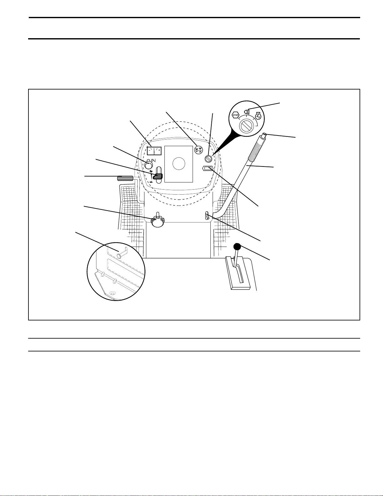
KNOW YOUR TRACTOR
READ THIS OWNER'S MANUAL AND SAFETY RULES BEFORE OPERATING YOUR TRACTOR
Compare the illustrations with your tractor to familiarize yourself with the locations of various controls and adjustments. Save
this manual for future reference.
THROTTLE
CONTROL
CLUTCH/BRAKE
PEDAL
HEIGHT ADJUSTMENT KNOB
FREEWHEEL
CONTROL
AMMETER
CHOKE
CONTROL
ATTACHMENT
CLUTCH SWITCH
IGNITION
SWITCH
LIGHT
SWITCH
POSITION
LIFT LEVER
PLUNGER
ATTACHMENT
LIFT LEVER
HOURMETER
PARKING BRAKE
MOTION
CONTROL
LEVER
Our tractors conform to the safety standards of the American National Standards Institute.
ATTACHMENT CLUTCH SWITCH: Used to engage the
mower blades, or other attachments mounted to your
tractor.
LIGHT SWITCH POSITION - Turns the headlights on.
THROTTLE CONTROL: Used to control engine speed.
CHOKE CONTROL: Used when starting a cold engine.
FREE WHEEL CONTROL - Disengages transmission for
pushing or slowly towing the tractor with the engine off.
CLUTCH/BRAKE PEDAL - Used for declutching and
braking the tractor and starting the engine.
HOURMETER - Indicates hours of operation.
HEIGHT ADJUSTMENT KNOB - Used to adjust the mower
cutting height.
FIG. 9
AMMETER - Indicates charging (+) or discharging (-) of
battery.
PARKING BRAKE - Locks clutch/brake pedal into the
brake position.
MOTION CONTROL LEVER - Selects the speed and
direction of tractor.
ATTACHMENT LIFT LEVER - Used to raise, lower, and
adjust the mower deck or other attachments mounted to
your tractor.
LIFT LEVER PLUNGER - Used to release attachment lift
lever when changing its position.
IGNITION SWITCH - Used for starting and stopping the
engine.
11
OPERATION
The operation of any tractor can result in foreign objects thrown into the eyes, which can
result in severe eye damage. Always wear safety glasses or eye shields while operating
your tractor or performing any adjustments or repairs. We recommend a wide vision safety
mask over spectacles or standard safety glasses.
HOW TO USE YOUR TRACTOR
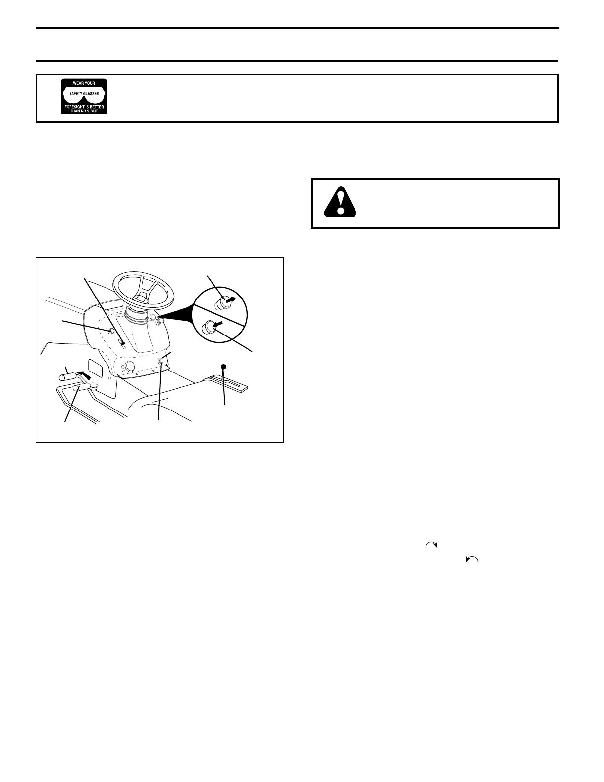
TO SET PARKING BRAKE (See Fig. 10)
Your tractor is equipped with an operator presence sensing
switch. When engine is running, any attempt by the
operator to leave the seat without first setting the parking
brake will shut off the engine.
• Depress clutch/brake pedal into full “BRAKE” position
and hold.
• Place parking brake lever in “ENGAGED” position and
release pressure from clutch/brake pedal. Pedal should
remain in “BRAKE” position. Make sure parking brake
will hold tractor secure.
THROTTLE
CONTROL
CHOKE
“BRAKE”
POSITION
CLUTCH/BRAKE PEDAL
“DRIVE” POSITION
STOPPING (See Fig. 10)
MOWER BLADES -
• To stop mower blades,move attachment clutch switch
to “DISENGAGED” position.
GROUND DRIVE -
• To stop ground drive, depress clutch/brake pedal into
full “BRAKE” position..
• Move motion control lever to neutral (N) position.
IMPORTANT: THE MOTION CONTROL LEVER DOES
NOT RETURN TO NEUTRAL (N) POSITION WHEN THE
CLUTCH/BRAKE PEDAL IS DEPRESSED.
ENGINE -
• Move throttle control to slow position.
NOTE: Failure to move throttle control to slow position and
allowing engine to idle before stopping may cause engine
to “backfire”.
• Turn ignition key to “OFF” position and remove key.
Always remove key when leaving tractor to prevent
unauthorized use.
• Never use choke to stop engine.
IMPORTANT: LEAVING THE IGNITION SWITCH IN ANY
POSITION OTHER THAN "OFF" WILL CAUSE THE
BATTERY TO BE DISCHARGED, (DEAD).
ATTACHMENT CLUTCH LEVER
PULL OUT TO “ENGAGE”
PARKING BRAKE
“ENGAGED”
POSITION
MOTION CONTROL
“DISENGAGED”
POSITION
LEVER
FIG. 10
PUSH IN TO
“DISENGAGE”
NOTE: Under certain conditions when tractor is standing
idle with the engine running, hot engine exhaust gases may
cause “browning” of grass. To eliminate this possibility,
always stop engine when stopping tractor on grass areas.
CAUTION: Always stop tractor completely, as described above, before leaving the operator's position; to empty
grass catcher, etc.
TO USE THROTTLE CONTROL (See Fig. 10)
Always operate engine at full throttle.
• Operating engine at less than full throttle reduces the
battery charging rate.
• Full throttle offers the best bagging and mower performance.
TO USE CHOKE CONTROL (See Fig. 10)
Use choke control whenever you are starting a cold engine.
Do not use to start a warm engine.
• To engage choke control, pull knob out. Slowly push
knob in to disengage.
TO MOVE FORWARD AND BACKWARD (See
Fig. 10)
The direction and speed of movement is controlled by the
motion control lever.
• Start tractor with motion control lever in neutral (N)
position.
• Release parking brake and clutch/brake pedal.
• Slowly move motion control lever to desired position.
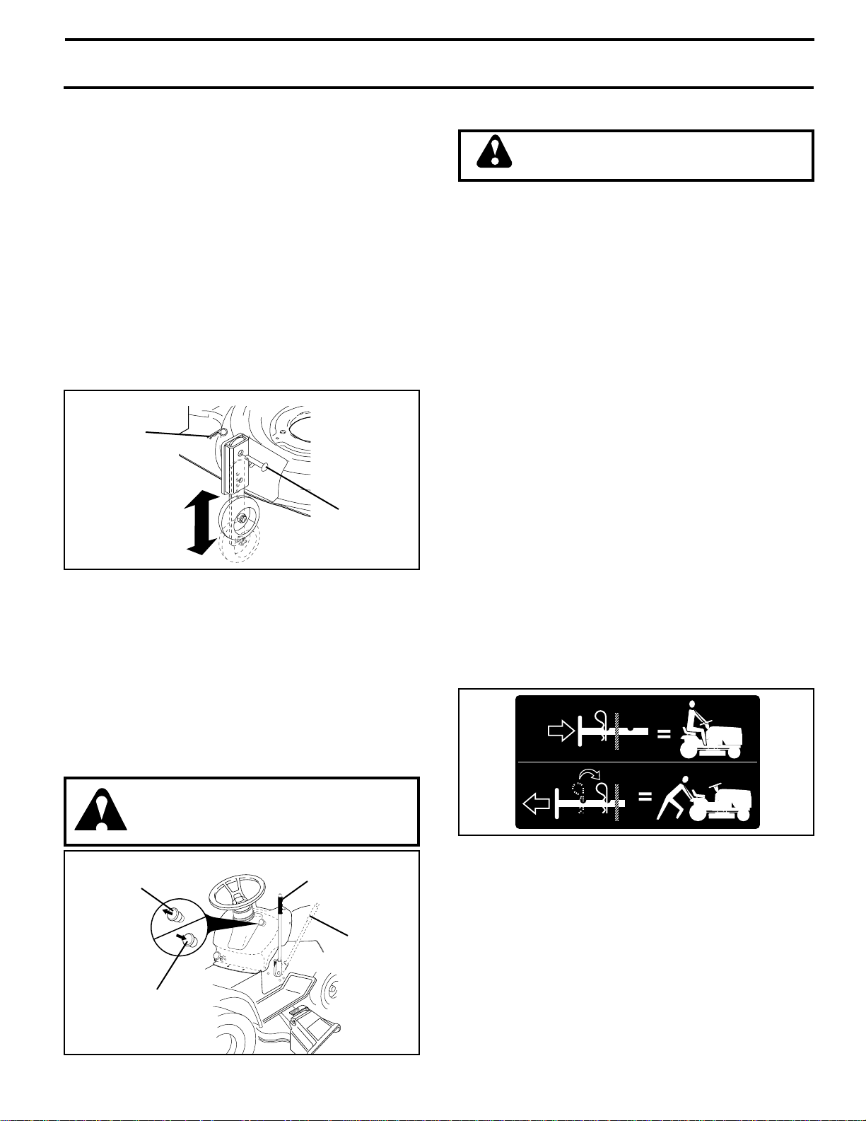
TO ADJUST MOWER CUTTING HEIGHT (See
Fig. 11)
The cutting height is controlled by turning the height
adjustment knob in desired direction.
• Turn knob clockwise ( ) to raise cutting height.
• Turn knob counterclockwise ( ) to lower cutting
height.
The cutting height range is approximately 1-1/2" to 4". The
heights are measured from the ground to the blade tip with
the engine not running. These heights are approximate
and may vary depending upon soil conditions, height of
grass and types of grass being mowed.
• The average lawn should be cut to approximately 2-1/2
inches during the cool season and to over 3 inches
during hot months. For healthier and better looking
lawns, mow often and after moderate growth.
• For best cutting performance, grass over 6 inches in
height should be mowed twice. Make the first cut
relatively high; the second to desired height.
12
OPERATION
TO ADJUST GAUGE WHEELS (See Fig. 11)
Gauge wheels are properly adjusted when they are slightly
off the ground when mower is at the desired cutting height
in operating position. Gauge wheels then keep the deck in
proper position to help prevent scalping in most terrain
conditions.
• Be sure tractor is on a flat level surface.
• Lower mower and adjust mower to desired cutting
height.
• Remove retainer spring and clevis pin which secure
each gauge wheel bar.
• Lower gauge wheels to ground. Raise gauge wheels
slightly to align holes in bracket and gauge wheel bar
and insert clevis pin. Gauge wheels should be slightly
off the ground.
• Replace retainer spring into clevis pin.
IMPORTANT: BE SURE TO READJUST GAUGE WHEELS
IF YOU CHANGE THE CUTTING HEIGHT OF THE MOWER
DECK.
RETAINER
SPRING
CLEVIS
PIN
FIG. 11
TO OPERATE MOWER (See Fig. 12)
Your tractor is equipped with an operator presence sensing
switch. Any attempt by the operator to leave the seat with
the engine running and the attachment clutch engaged will
shut off the engine.
• Select desired height of cut.
• Lower mower with attachment lift control.
• Start mower blades by engaging attachment clutch
control.
• TO STOP MOWER BLADES - disengage attachment
clutch control.
CAUTION: Do not operate the mower
without either the entire grass catcher,
on mowers so equipped, or the discharge guard in place.
ATTACHMENT CLUTCH
SWITCH PULL OUT TO
"ENGAGE"
PUSH IN TO
"DISENGAGE"
ATTACHMENT
LIFT LEVER
HIGH POSITION
LOW
POSITION
TO OPERATE ON HILLS
CAUTION: Do not drive up or down
hills with slopes greater than 15° and
do not drive across any slope.
• Choose the slowest speed before starting up or down
hills.
• Avoid stopping or changing speed on hills.
• If slowing is necessary, move throttle control lever to
slower position.
• If stopping is absolutely necessary, push clutch/brake
pedal quickly to brake position and engage parking
brake.
• Move motion control lever to neutral (N) position.
IMPORTANT: THE MOTION CONTROL LEVER DOES
NOT RETURN TO NEUTRAL (N) POSITION WHEN THE
CLUTCH/BRAKE PEDAL IS DEPRESSED.
• To restart movement, slowly release parking brake and
clutch/brake pedal.
• Slowly move motion control lever to slowest setting.
• Make all turns slowly.
TO TRANSPORT (See Figs. 9 and 13)
When pushing or towing your tractor, be sure to disengage
transmission by placing freewheel control in freewheeling
position. Free wheel control is located at the rear drawbar
of tractor.
• Raise attachment lift to highest position with attachment lift control.
• Pull freewheel control knob out and hold in position by
inserting retainer spring into forward hole of control
rod.
• Do not push or tow tractor at more than two (2) MPH.
• To reengage transmission, reverse above procedure.
NOTE: To protect hood from damage when transporting
your tractor on a truck or a trailer, be sure hood is closed
and secured to tractor. Use an appropriate means of tying
hood to tractor (rope, cord, etc.).
FIG. 13
BEFORE STARTING THE ENGINE
CHECK ENGINE OIL LEVEL (See Fig. 18)
• The engine in your tractor has been shipped, from the
factory, already filled with summer weight oil.
• Check engine oil with tractor on level ground.
• Unthread and remove oil fill cap/dipstick; wipe oil off.
Reinsert the dipstick into the tube and rest oil fill cap on
the tube. Do not thread the cap onto the tube. Remove
and read oil level. If necessary, add oil until “FULL”
mark on dipstick is reached. Do not overfill.
FIG. 12
13

OPERATION
• For cold weather operation you should change oil for
easier starting (See “OIL VISCOSITY CHART” in the
Customer Responsibilities section of this manual).
• To change engine oil, see the Customer Responsibilities section in this manual.
ADD GASOLINE
• Fill fuel tank. Use fresh, clean, regular unleaded
gasoline with a minimum of 87 octane. (Use of leaded
gasoline will increase carbon and lead oxide deposits
and reduce valve life). Do not mix oil with gasoline.
Purchase fuel in quantities that can be used within 30
days to assure fuel freshness.
IMPORTANT: WHEN OPERATING IN TEMPERATURES
BELOW 32°F(0°C), USE FRESH, CLEAN WINTER GRADE
GASOLINE TO HELP INSURE GOOD COLD WEATHER
STARTING.
WARNING: Experience indicates that alcohol blended
fuels (called gasohol or using ethanol or methanol) can
attract moisture which leads to separation and formation of
acids during storage. Acidic gas can damage the fuel
system of an engine while in storage. To avoid engine
problems, the fuel system should be emptied before storage of 30 days or longer. Drain the gas tank, start the
engine and let it run until the fuel lines and carburetor are
empty. Use fresh fuel next season. See Storage Instructions for additional information. Never use engine or
carburetor cleaner products in the fuel tank or permanent
damage may occur.
CAUTION: Fill to bottom of gas tank
filler neck. Do not overfill. Wipe off any
spilled oil or fuel. Do not store, spill or
use gasoline near an open flame.
• The attachments and ground drive can now be used. If
the engine does not accept the load, restart the engine
and allow it to warm up for one minute using the choke
as described above.
COLD WEATHER STARTING (50° F and below)
• When engine starts, slowly push choke control in until
the engine begins to run smoothly. Continue to push
the choke control in small steps allowing the engine to
accept small changes in speed and load, until the
choke control is fully in. If the engine starts to run
roughly, pull the choke control out slightly for a few
seconds and then continue to push the control in
slowly. This may require an engine warm-up period
from several seconds to several minutes, depending
on the temperature.
AUTOMATIC TRANSMISSION WARM UP
• Before driving the unit in cold weather, the transmission should be warmed up as follows:
• Be sure the tractor is on level ground.
• Place the motion control lever in neutral.
Release the parking brake and let the clutch/brake
slowly return to operating position.
• Allow one minute for transmission to warm up. This
can be done during the engine warm up period.
• The attachments can be used during the engine warmup period after the transmission has been warmed up
and may require the choke control be pulled out slightly.
NOTE: If at a high altitude (above 3000 feet) or in cold
temperatures (below 32 F) the carburetor fuel mixture may
need to be adjusted for best engine performance. See “TO
ADJUST CARBURETOR” in the Service and Adjustments
section of this manual.
TO START ENGINE (See Fig. 10)
When starting the engine for the first time or if the engine
has run out of fuel, it will take extra cranking time to move
fuel from the tank to the engine.
• Be sure freewheel control is in the transmission engaged position.
• Sit on seat in operating position, depress clutch/brake
pedal and set parking brake.
• Place motion control lever in neutral (N) position.
• Move attachment clutch to “DISENGAGED” position.
• Move throttle control to fast position
• Pull choke control out for a cold engine start attempt.
For a warm engine start attempt the choke control may
not be needed.
NOTE: Before starting, read the warm and cold starting
procedures below.
• Insert key into ignition and turn key clockwise to “START”
position and release key as soon as engine starts. Do
not run starter continuously for more than fifteen seconds per minute. If the engine does not start after
several attempts, push choke control in, wait a few
minutes and try again. If engine still does not start, pull
the choke control out and retry.
WARM WEATHER STARTING (50° F and above)
• When engine starts, slowly push choke control in until
the engine begins to run smoothly. If the engine starts
to run roughly, pull the choke control out slightly for a
few seconds and then continue to push the control in
slowly.
PURGE TRANSMISSION
CAUTION: Never engage or disengage
freewheel lever while the engine is running.
To ensure proper operation and performance, it is recommended that the transmission be purged before operating
tractor for the first time. This procedure will remove any
trapped air inside the transmission which may have developed during shipping of your tractor.
IMPORTANT: SHOULD YOUR TRANSMISSION
REQUIRE REMOVAL FOR SERVICE OR
REPLACEMENT, IT SHOULD BE PURGED AFTER
REINSTALLATION BEFORE OPERATING THE
TRACTOR.
• Place tractor safely on level surface with engine off and
parking brake set.
• Disengage transmission by placing freewheel control
in freewheeling position (See “TO TRANSPORT” in
this section of manual).
• Sitting in the tractor seat, start engine. After the engine
is running, move throttle control to slow position. With
motion control lever in neutral (N) position, slowly
disengage clutch/brake pedal.
• Move motion control lever to full forward position and
hold for five (5) seconds. Move lever to full reverse
position and hold for five (5) seconds. Repeat this
procedure three (3) times.
NOTE: During this procedure there will be no movement of
drive wheels. The air is being removed from hydraulic drive
system.
14
OPERATION
• Move motion control lever to neutral (N) position. Shutoff engine and set parking brake.
• Engage transmission by placing freewheel control in
driving position (See “TO TRANSPORT” in this section
of manual).
• Sitting in the tractor seat, start engine. After the engine
is running, move throttle control to half (1/2) speed.
With motion control lever in neutral (N) position, slowly
disengage clutch/brake pedal.
• Slowly move motion control lever forward, after the
tractor moves approximately five (5) feet, slowly move
motion control lever to reverse position. After the
tractor moves approximately five (5) feet return the
motion control lever to the neutral (N) position. Repeat
this procedure with the motion control lever three (3)
times.
• Your tractor is now purged and now ready for normal
operation.
MOWING TIPS
• Tire chains cannot be used when the mower housing is
attached to tractor.
• Mower should be properly leveled for best mowing
performance. See “TO LEVEL MOWER HOUSING” in
the Service and Adjustments section of this manual.
• The left hand side of mower should be used for trimming.
• Drive so that clippings are discharged onto the area
that has been cut. Have the cut area to the right of the
machine. This will result in a more even distribution of
clippings and more uniform cutting.
• When mowing large areas, start by turning to the right
so that clippings will discharge away from shrubs,
fences, driveways, etc. After one or two rounds, mow
in the opposite direction making left hand turns until
finished (See Fig. 14 ).
• If grass is extremely tall, it should be mowed twice to
reduce load and possible fire hazard from dried clippings. Make first cut relatively high; the second to the
desired height.
• Do not mow grass when it is wet. Wet grass will plug
mower and leave undesirable clumps. Allow grass to
dry before mowing.
• Always operate engine at full throttle when mowing to
assure better mowing performance and proper discharge of material. Regulate ground speed by selecting a low enough gear to give the mower cutting
performance as well as the quality of cut desired.
• When operating attachments, select a ground speed
that will suit the terrain and give best performance of
the attachment being used.
MULCHING MOWING TIPS
IMPORTANT: FOR BEST PERFORMANCE, KEEP
MOWER HOUSING FREE OF BUILT-UP GRASS
AND TRASH. CLEAN AFTER EACH USE.
• The special mulching blade will recut the grass clippings many times and reduce them in size so that as
they fall onto the lawn they will disperse into the grass
and not be noticed. Also, the mulched grass will
biodegrade quickly to provide nutrients for the lawn.
Always mulch with your highest engine (blade) speed
as this will provide the best recutting action of the
blades.
• Avoid cutting your lawn when it is wet. Wet grass tends
to form clumps and interferes with the mulching action.
The best time to mow your lawn is the early afternoon.
At this time the grass has dried and the newly cut area
will not be exposed to the direct sun.
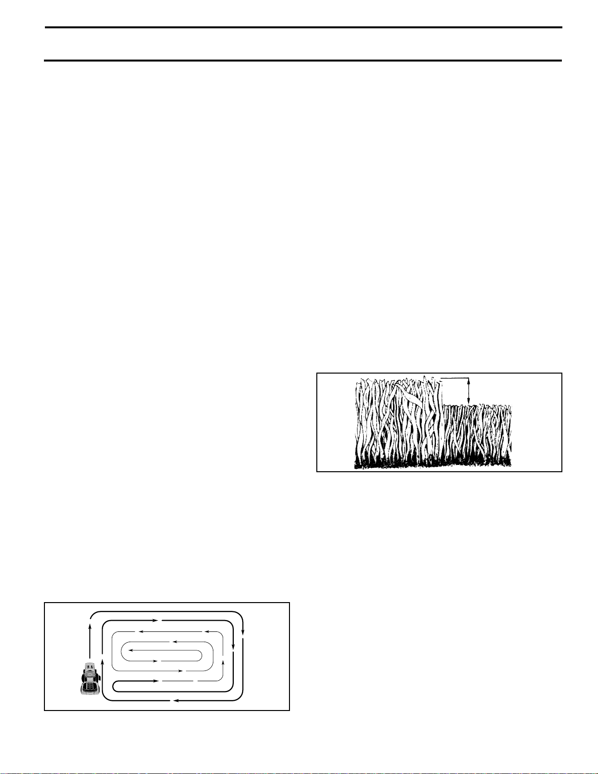
• For best results, adjust the mower cutting height so that
the mower cuts off only the top one-third of the grass
blades (See Fig. 15). For extremely heavy mulching,
reduce your width of cut and mow slowly.
• Certain types of grass and grass conditions may require that an area be mulched a second time to completely hide the clippings. When doing a second cut,
mow across or perpendicular to the first cut path.
• Change your cutting pattern from week to week. Mow
north to south one week then change to east to west the
next week. This will help prevent matting and graining
of the lawn.
MAX 1/3
FIG. 15
FIG. 14
15
 Loading...