

Page 1
917.375950
Owner’s Manual
196578 Rev. 1 01.27.05 BY Printed in U.S.A.
Page 2
SAFETY RULES
Safe Operation Practices for Walk-Behind Mowers
IMPORTANT: THIS CUTTING MACHINE IS CAPABLE OF AMPUTATING HANDS AND FEET AND THROW ING OBJECTS. FAILURE
TO OBSERVE THE FOLLOWING SAFETY INSTRUCTIONS COULD RESULT IN SERIOUS INJURY OR DEATH.
Look for this symbol to point out im por tant safety precautions. It means
CAUTION!!! BE COME ALERT!!! YOUR
SAFE TY IS IN VOLVED.
CAUTION: Always disconnect spark plug
wire and place wire where it cannot contact
spark plug in order to prevent ac ci den tal
starting when setting up, trans port ing,
adjusting or making re pairs.
WARNING: Engine exhaust, some of its
con stit u ents, and certain vehicle com po nents contain or emit chem i cals known to
the State of Cal i for nia to cause can cer and
birth defects or oth er re pro duc tive harm.
WARNING: Battery posts, terminals and
related ac ces so ries contain lead and lead
compounds, chemicals known to the State
of Cal i for nia to cause can cer and birth
defects or oth er re pro duc tive harm. Wash
hands after handling.
CAUTION: Muffl er and other engine parts
become extremely hot during operation
and remain hot after engine has stopped.
To avoid severe burns on contact, stay away
from these areas.
I. GENERAL OPERATION
• Read, understand, and follow all instructions on the
machine and in the manual(s) before starting. Be thor ough ly familiar with the controls and the proper use of
the machine before starting.
• Do not put hands or feet near or under rotating parts.
Keep clear of the discharge opening at all times.
• Only allow responsible individuals, who are familiar
with the instructions, to operate the machine.
• Clear the area of objects such as rocks, toys, wire,
bones, sticks, etc., which could be picked up and thrown
by the blade.
• Be sure the area is clear of other people before mow ing. Stop machine if anyone enters the area.
• Do not operate the mower when barefoot or wearing
open sandals. Always wear substantial foot wear.
• Do not pull mower backwards unless absolutely nec es sary. Always look down and behind before and while
moving backwards.
• Never direct discharged material toward anyone.
Avoid discharging material against a wall or obstruction. Material may richochet back toward the operator.
Stop the blade when crossing gravel surfaces.
• Do not operate the mower without proper guards,
plates, grass catcher or other safety protective devices
in place.
• See manufacturer’s instructions for proper operation
and installation of accessories. Only use accessories
approved by the manufacturer.
• Stop the blade(s) when crossing gravel drives, walks,
or roads.
• Stop the engine (motor) whenever you leave the equip ment, before cleaning the mower or unclogging the
chute.
• Shut the engine (motor) off and wait until the blade comes
to complete stop before removing grass catch er.
• Mow only in daylight or good artifi cial light.
• Do not operate the machine while under the infl uence
of alcohol or drugs.
• Never operate machine in wet grass. Always be sure of
your footing: keep a fi rm hold on the handle and walk;
never run.
• Disengage the self-propelled mechanism or drive clutch
on mowers so equipped before starting the engine (motor).
• If the equipment should start to vibrate abnormally,
stop the engine (motor) and check immediately for the
cause. Vibration is generally a warning of trouble.
• Always wear safety goggles or safety glasses with side
shields when operating mower.
II. SLOPE OPERATION
Slopes are a major factor related to slip and fall accidents
which can result in severe injury. All slopes require extra
caution. If you feel uneasy on a slope, do not mow it.
DO:
• Mow across the face of slopes: never up and down. Exercise extreme caution when changing direction on slopes.
• Remove obstacles such as rocks, tree limbs, etc.
• Watch for holes, ruts, or bumps. Tall grass can hide
obstacles.
DO NOT:
• Do not trim near drop-offs, ditches or embankments.
The operator could lose footing or balance.
• Do not trim excessively steep slopes.
• Do not mow on wet grass. Reduced footing could cause
slipping.
III. CHILDREN
Tragic accidents can occur if the operator is not alert to
the presence of children. Children are often attracted to
Never
the machine and the mowing activity.
assume that
children will remain where you last saw them.
• Keep children out of the trimming area and under the
watchful care of another re spon si ble adult.
• Be alert and turn machine off if children enter the
area.
• Before and while walking backwards, look behind and
down
for small children.
• Never allow children to operate the machine.
• Use extra care when approaching blind corners, shrubs,
trees, or other objects that may obscure vision.
IV. SAFE HANDLING OF GASOLINE
Use extreme care in handling gasoline. Gasoline is extremely fl ammable and the vapors are explosive.
• Extinguish all cigarettes, cigars, pipes and other sources
of ignition.
• Use only an approved container.
• Never remove gas cap or add fuel with the engine run-
2
ning. Allow engine to cool before refueling.
Page 3

• Never refuel the machine indoors.
• Never store the machine or fuel container where there
is an open fl ame, spark or pilot light such as a water
heater or on other appliances.
• Never fi ll containers inside a vehicle, on a truck or trailer
bed with a plastic liner. Always place containers on
the ground away from your vehicle before fi lling.
• Remove gas-powered equipment from the truck or trailer
and refuel it on the ground. If this is not possible, then
refuel such equipment with a portable container, rather
than from a gasoline dispenser nozzle.
• Keep the nozzle in contact with the rim of the fuel tank
or container opening at all times until fueling is complete.
Do not use a nozzle lock-open device.
• If fuel is spilled on clothing, change clothing immediately.
• Never overfi ll fuel tank. Replace gas cap and tighten
securely.
V. GENERAL SERVICE
• Never run a machine inside a closed area.
• Never make adjustments or repairs with the engine
(motor) running. Disconnect spark plug wire, and keep
WARNING: This lawn mower is equipped with an internal com bus tion engine and should not be used on or near any
un im proved forest-covered, brush-covered or grass-cov ered land unless the engine’s exhaust system is equipped with
a spark arrester meeting applicable local or state laws (if any). If a spark arrester is used, it should be maintained in
effective working order by the operator.
In the state of California the above is required by law (Section 4442 of the California Public Resources Code). Other
states may have similar laws. Federal laws apply on federal lands. A spark arrester for the muffl er is available
through your nearest Sears Parts & Repair center.
wire away from plug to prevent accidental starting.
• Keep nuts and bolts, especially blade attachement
bolts, tight and keep equipment in good condition.
• Never tamper with safety devices. Check their proper
operation regularly.
• Keep machine free of grass, leaves, or other debris
build-up. Clean oil or fuel spillage. Allow machine to
cool before storing.
• Stop and inspect the equipment if you strike an object.
Repair, if necessary, before restarting.
• Never attempt to make wheel height adjustments while
the engine (motor) is running.
• Grass catcher components are subject to wear, dam age, and deterioration, which could expose moving
parts or allow objects to be thrown. Frequently check
com po nents and replace with manufacturer’s rec om mend ed parts, when necessary.
• Mower blade is sharp and can cut. Wrap the blade or
wear gloves, and use extra caution when servicing it.
• Do not change the engine governor setting or overspeed
the engine.
• Maintain or replace safety and instruction labels, as
necessary.
CONGRATULATIONS on your purchase of a new lawn
mower. It has been designed, engineered and man u fac tured
to give you the best possible dependability and performance.
Should you experience any problem you cannot easily
remedy, please contact your nearest authorized service
center/department. We have competent, well-trained
tech ni cians and the proper tools to service or repair this
lawn mower.
Please read and retain this manual. The instructions will
enable you to assemble and maintain your lawn mower
properly. Always observe the “SAFETY RULES”.
SERIAL
NUMBER: _________________________________
DATE OF PURCHASE: _______________________
THE MODEL AND SERIAL NUMBERS WILL BE FOUND
ON A DECAL ATTACHED TO THE REAR OF THE LAWN
MOWER HOUSING.
YOU SHOULD RECORD BOTH SERIAL NUMBER AND
DATE OF PURCHASE AND KEEP IN A SAFE PLACE
FOR FUTURE REFERENCE.
PRODUCT SPECIFICATIONS
Gasoline Capacity 1.6 Quarts
and Type: (Unleaded Regular Only)
Oil Type (API SG–SL): SAE 30 (above 0°C / 32°F)
SAE 5W-30 (below 0°C / 32°F)
Oil Capacity: 20 Ounces
Spark Plug: RJ19LM or J19LM (Gap: .030")
Blade Bolt Torque: 35-40 ft. lbs.
CUSTOMER RESPONSIBILITIES
• Read and observe the safety rules.
• Follow a regular schedule in maintaining, caring for and
using your lawn mower.
• Follow the instructions under “Maintenance” and “Stor age” sec tions of this own er’s manual.
TABLE OF CONTENTS
SAFETY RULES .........................................................2-3
PRODUCT SPECIFICATIONS....................................... 3
CUSTOMER RESPONSIBILITIES................................. 3
ASSEMBLY................................................................. 4-5
OPERATION ............................................................. 6-10
MAINTENANCE SCHEDULE ...................................... 11
MAINTENANCE ...................................................... 11-13
SERVICE AND AD JUST MENTS ............................14-15
STORAGE ...............................................................15-16
TROU BLE SHOOT ING ................................................. 17
REPAIR PARTS....................................................... 18-23
WARRANTY................................................................. 24
3
Page 4
ASSEMBLY
Read these instructions and this man u al in its entirety before
you attempt to assemble or operate your new lawn mow er.
IMPORTANT: THIS LAWN MOWER IS SHIPPED WITH OUT OIL OR GASOLINE IN THE ENGINE.
Your new lawn mower has been as sem bled at the factory
with the ex cep tion of those parts left unassembled for shipping purposes. All parts such as nuts, washers, bolts, etc.,
necessary to com plete the as sem bly have been placed in
the parts bag. To ensure safe and proper operation of your
lawn mow er, all parts and hard ware you assemble must
be tightened se cure ly. Use the correct tools as nec es sary
to ensure proper tightness.
TO RE MOVE LAWN MOW ER FROM CAR TON
1. Remove loose parts included with mower.
2. Cut down two end corners of car ton and lay end panel
down fl at.
3. Remove all packing materials ex cept padding be tween
upper and lower handle and padding holding operator
presence control bar to up per handle.
4. Roll lawn mower out of carton and check carton thorougly for ad di tion al loose parts.
OPERATOR
PRESENCE
CONTROL
BAR
LIFT
UP
MOWING
PO SI TION
LIFT
UP
UPPER
HANDLE
HANDLE
KNOB
LOWER
HANDLE
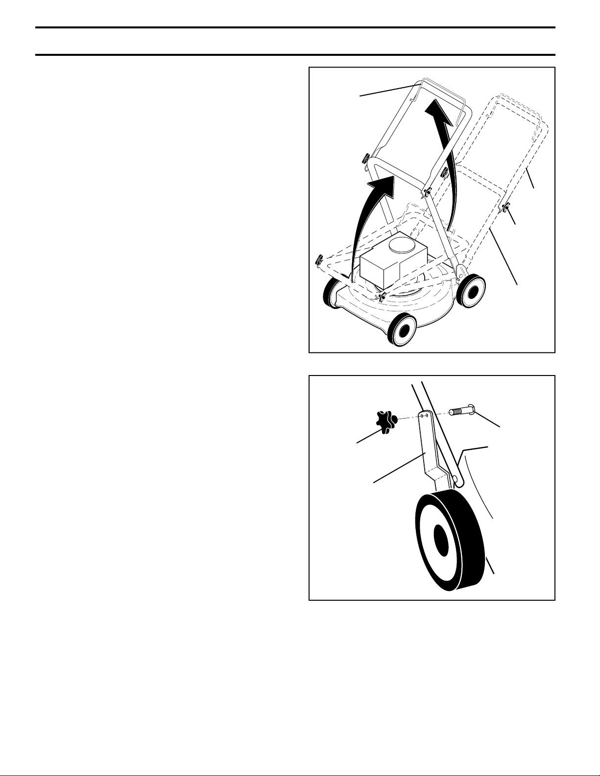
HOW TO SET UP YOUR LAWN MOW ER
TO UNFOLD HANDLE (See Figs. 1 and 2)
IMPORTANT: UNFOLD HANDLE CAREFULLY SO AS
NOT TO PINCH OR DAMAGE CON TROL CABLES.
1. Raise lower handle to operating position and align hole
in handle with one of the height positioning holes in
the handle bracket.
2. Insert handle bolt through handle and bracket and
secure with knob.
3. Repeat for opposite side of handle.
4. Remove protective padding, raise upper handle section into place on lower handle and tighten both handle
knobs.
5. Remove packing material from around control bar.
Your handles may be adjusted for your mowing comfort.
Refer to “ADJUST HANDLE” in the Service and Ad just ments
sec tion of this man u al.
FIG. 1
BOLT
KNOB
HANDLE
BRACKET
FIG. 2
4
Page 5
ASSEMBLY
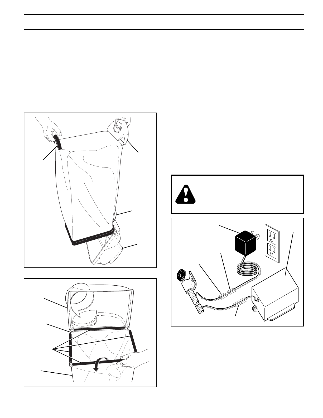
TO ASSEMBLE GRASS CATCHER
(See Figs. 3 and 4)
1. Slide grass catcher bag over the frame. Make sure
the rear handle is on top (the same side as the front
handle) and the strap is on the bottom.
2. Slip vinyl bindings over frame.
NOTE: If vinyl bindings are too stiff, hold them in warm water
for a few minutes. If bag gets wet, let it dry before using.
3. Close grass catcher door.
NOTE: When fully closed, door will “snap” shut over frame
and vinyl bindings.
REAR
STRAP
HANDLE
FRONT
HANDLE
TO INSTALL ATTACHMENTS
Your lawn mower was shipped ready to be used as a
mulcher. To convert mower to bagging or discharging,
see “TO CON VERT MOWER” in the Operation section of
this man u al.
TO PREPARE BATTERY (See Fig. 5)
NOTE: Your battery must be charged before you can start your
lawn mower.
1. Con nect battery charger con nec tor (male) to harness
con nec tor (fe male).
2. Plug battery charger into 110 volt A.C. outlet.
3. Leave battery charger connected for 24 hours before
starting your engine for the fi rst time.
4. After charging, disconnect harness connector (female)
from bat tery charger connector (male).
Connect your battery charger to charge battery after each
use.
IMPORTANT: The engine will not recharge your battery.
At the end of the mowing season the battery should be
charged for 48 hours to protect the battery during winter
storage.
CAUTION: Always disconnect the
en gine connector (male) from the
battery connector (female) to prevent
ac ci den tal start ing when transporting
or stor ing your lawn mower after the
season.
DOOR
GRASS
CATCHER
FRAME
VINYL
BINDINGS
BAG
FIG. 3
DOOR
BATTERY CHARGER
CHARGER
CONNECTOR
HARNESS
CONNECTOR
(FEMALE)
ENGINE CONNECTOR (MALE)
(MALE)
FIG. 5
BATTERY
BOX
FIG. 4
5
Page 6
OPERATION
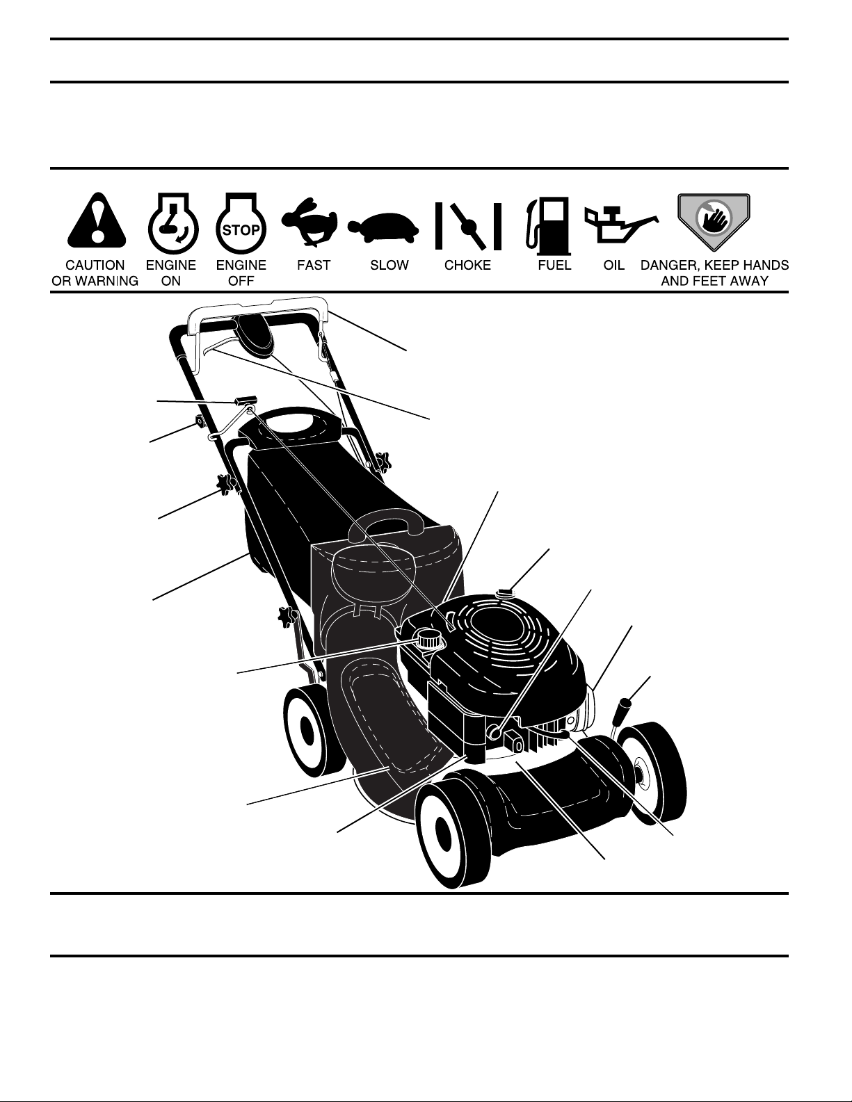
KNOW YOUR LAWN MOWER
READ THIS OWNER'S MANUAL AND SAFETY RULES BEFORE OPERATING YOUR LAWN MOWER.
Compare the illustrations with your lawn mower to familiarize yourself with the location of various controls and adjustments.
Save this manual for future reference.
These symbols may appear on your mower or in literature supplied with it. Learn and understand their meaning.
OPERATOR PRESENCE CON TROL BAR
AUXILIARY
STARTER
HANDLE
DRIVE CONTROL LEVER
KEY
START
SWITCH
HANDLE
KNOB
GRASS
CATCHER
GAS O LINE FILL ER CAP
MULCHER DOOR
AIR FILTER
IMPORTANT: This lawn mower is shipped
WITHOUT OIL OR GASOLINE in the engine.
DRIVE COVER
EN GINE OIL CAP
WITH DIPSTICK
PRIMER
MUFFLER
DUAL POINT HEIGHT
ADJUSTER LEVER
SPARK PLUG
HOUSING
MEETS CPSC SAFETY REQUIREMENTS
Our rotary walk-behind power lawn mowers conform to the safety standards of the American National Standards Institute
and the U.S. Consumer Product Safety Commission. The blade turns when the engine is running.
OPERATOR PRESENCE CONTROL BAR – must be held
down to the handle to start engine. Release to stop engine.
MULCHER DOOR – allows conversion to discharge or
bagging operation.
PRIMER – pumps additional fuel from the carburetor to the
cylinder for use when starting a cold engine.
AUXILIARY STARTER HANDLE – used for starting engine.
DRIVE CONTROL LEVER – used to engage power-pro-
pelled forward motion lawn mower.
DUAL POINT HEIGHT ADJUSTER – used to adjust cutting
height of lawn mower.
KEY START SWITCH – used for start ing the engine.
6
Page 7
OPERATION
The operation of any lawn mower can result in foreign objects thrown into the eyes, which can result
in severe eye damage. Always wear safety glasses or eye shields while operating your lawn mower or
performing any adjustments or repairs. We recommend standard safety glasses or a wide vision safety
mask over spectacles.
HOW TO USE YOUR LAWN MOWER
ENGINE SPEED
The engine speed was set at the factory for optimum performance. Speed is not adjustable.
ENGINE ZONE CONTROL
CAUTION: Federal regulations require
an engine control to be installed on this
lawn mower in order to minimize the risk
of blade contact injury. Do not un der
any cir cum stanc es attempt to defeat
the function of the operator control.
The blade turns when the engine is
running.
• Your lawn mower is equipped with an operator presence
control bar which requires the operator to be positioned
behind the lawn mower handle to start and operate the
lawn mower.
DRIVE CONTROL (See Fig. 6)
• Self-propelling is controlled by hold ing the operator
presence control bar down to the handle and pulling
the drive control lever rearward to the handle. The
farther toward the handle the lever is pulled, the faster
the unit will travel.
• Forward motion will stop when either the operator presence control bar or drive control lever are released. To
stop forward motion without stop ping engine, re lease
the drive control lever only. Hold op er a tor presence
control bar down against handle to con tin ue mowing
without self-propelling.
NOTE: If after releasing the drive control the mower will
not roll backwards, push the mower forward slightly to
disengage drive wheels.
OPERATOR PRESENCE CONTROL BAR
DRIVE
CONTROL
LEVER
ADJUSTMENT
TURNBUCKLE
(ON UNDERSIDE)
TO ENGAGE
DRIVE
CONTROL
DRIVE
CONTROL
DISENGAGED
2. Turn nut on underside of drive control to increase drive
speed.
3. Operate mower to test drive speed. Readjust as required.
4. If condition fails to improve after the above steps (forward speed remains the same), your drive belt is worn
and should be re placed.
TO ADJUST CUTTING HEIGHT (See Fig. 7)
Both front wheels are adjusted by a single lever on the left
front wheel. Likewise, both rear wheels are adjusted by a
single lever on the left rear wheel.
• Pull adjuster lever toward wheel. To raise mower, move
lever forward to desired position. To lower mow er, move
the lever toward the rear.
Be sure to adjust both front and rear wheels to same height.
LEVER BACKWARD
TO LOWER MOWER
LEVER FORWARD
TO RAISE MOWER
HEIGHT
ADJUSTER
LEVER
FIG. 7
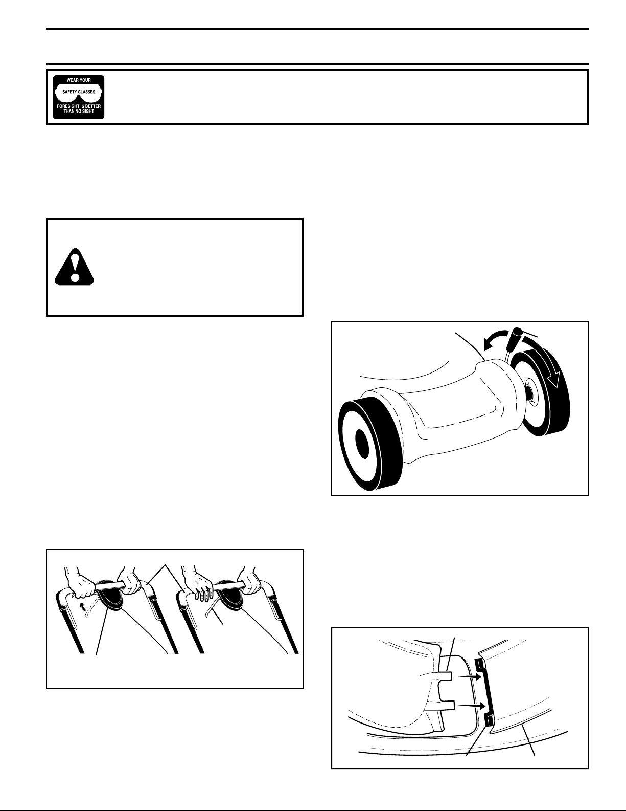
TO CONVERT MOWER (See Figs. 8 thru 10)
Your lawn mower was shipped ready to be used as a mulcher.
To convert to rear bagging or side discharging:
REAR BAGGING
• Remove knob securing mulcher door to mower housing.
• Open mulcher door and insert tabs of discharge chute
into hinge bracket opening and position rear of chute
over threaded stud.
DISCHARGE CHUTE TABS
FIG. 6
DRIVE CONTROL ADJUSTMENT (See Fig. 6)
Over time, the drive control system may become “loose”,
resulting in decreased speed. There is a turnbuckle on the
un der side of the drive control housing to increase tension
on the drive cable. Pro ceed as follows:
1. Turn unit off and disconnect spark plug wire from plug.
HINGE BRACKET MULCHER DOOR
7
FIG. 8
Page 8
OPERATION
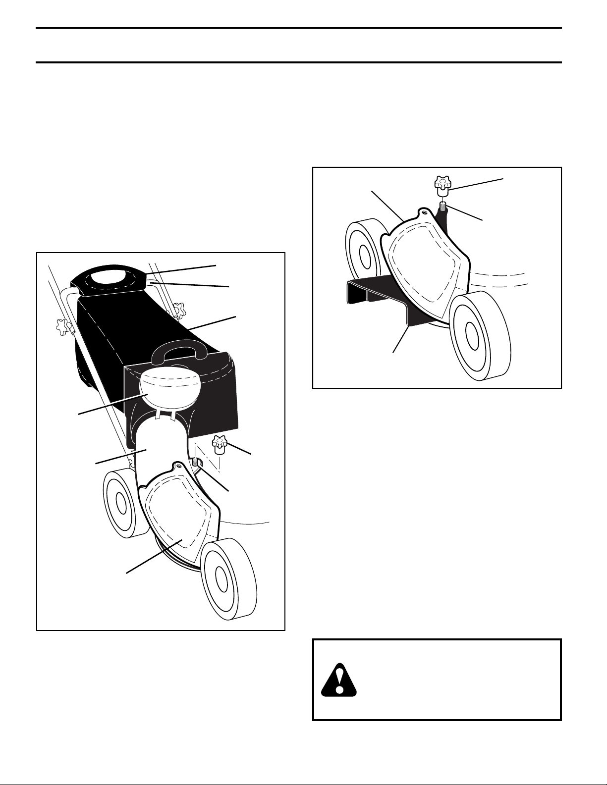
• Secure rear of discharge chute to lawn mower housing
with knob.
• Place rear handle of grass catcher on the crossbar of
the lawn mower's lower handle as shown.
• Lift the round door of the discharge chute and place
the grass catcher into place on the discharge chute.
NOTE: Be sure round door of discharge chute rests on
grass catcher as shown.
• Mower is now ready for rear bagging operation.
• To conver t to mulching operation, remove grass catch er
and discharge chute. Secure mulcher door to mower
housing with knob.
• To convert to side dis charg ing operation, remove grass
catch er and discharge chute. Install side discharge
defl ector and secure it to mower housing with knob.
REAR HANDLE
CROSSBAR
GRASS
CATCHER
• Mower is now ready for side discharging operation.
• To convert to mulching operation, side dis charge defl ector must be removed and mulcher door secured to
mower housing with knob.
• To convert to rear bagging operation, side discharge
defl ector must be removed; discharge chute and grass
catcher installed and discharge chute secured to mower
housing with knob.
KNOBMULCHER
DOOR
THREADED
STUD
SIDE
DISCHARGE
DEFLECTOR
ROUND
DOOR
KNOB
DISCHARGE
CHUTE
THREADED
STUD
MULCHER
DOOR
FIG. 9
SIDE DISCHARGING
• Grass catcher and discharge chute must be removed.
• Open mulcher door and install front of side dis charge
defl ector beneath it as shown.
• Secure rear of side discharge defl ector to lawn mower
housing with knob.
FIG. 10
SIMPLE STEPS TO REMEMBER WHEN
CONVERTING YOUR LAWN MOWER
FOR MULCHING -
1. Grass catcher, discharge chute and side discharge
defl ector removed.
2. Mulcher door secured to mower housing with knob.
FOR REAR BAGGING -
1. Side discharge defl ector removed.
2. Grass catcher and discharge chute installed with
discharge chute secured to lawn mower housing with
knob.
3. Round door of discharge chute resting on top of grass
catcher.
FOR SIDE DISCHARGING -
1. Grass catcher and discharge chute removed.
2. Side discharge defl ector installed and secured to mower
housing with knob.
CAUTION: Do not run your lawn mower
with out mulcher door closed; side discharge defl ector installed, or discharge
chute and ap proved grass catcher in
place. Never at tempt to op er ate the lawn
mow er with mulcher door or round door
re moved or propped open.
8
Page 9

OPERATION
TO EMPTY GRASS CATCHER (See Figs. 11 –12)
1. Open round door of discharge chute to move starter
rope out and away from grass catcher.
OPEN
FIG. 11
2. Remove grass catcher with clippings from lawn mower
using both front and rear handles.
3. Empty clippings from bag using rear handle and strap.
The weight of the grass will open the door.
4. Snap door shut over frame before installing grass
catcher on mower.
NOTE: Do not drag the bag when emptying; it will cause
unnecessary wear.
FRONT
HANDLE
ROUND
DOOR
STARTER
ROPE
BEFORE STARTING ENGINE
ADD OIL (See Fig. 13)
Your lawnmower is shipped without oil in the engine. For type
and grade of oil to use, see “EN GINE” in the Maintenance
section of this manual.
CAUTION: DO NOT overfi ll engine
with oil, or it will smoke heavily from
the muffl er on startup.
1. Be sure lawnmower is level.
2. Remove oil dipstick from oil fi ll spout.
3. You receive a container of oil with the unit. Slowly
pour the entire container down the oil fi ll spout into the
engine.
NOTE: Initial oil fi ll requires only 18 oz. due to residual oil
in engine from the manufacturers 100% quality testing.
When changing oil you may need 20 oz.
4. Insert and tighten dipstick.
IMPORTANT:
• Check oil level before each use. Add oil if needed. Fill
to full line on dipstick.
• Change the oil after every 25 hours of operation or each
season. You may need to change the oil more often
under dusty, dirty conditions. See “TO CHANGE ENGINE OIL” in the Maintenance section of this manual.
STRAP
REAR
HANDLE
FRONT
HANDLE
DOOR
GASOLINE
FILLER CAP
PRIMER
ENGINE
OIL CAP
FIG. 13
FIG. 12
9
Page 10

OPERATION
ADD GASOLINE (See Fig. 13)
• Fill fuel tank to bottom of tank fi ller neck. Do not overfi ll. Use fresh, clean, regular unleaded gasoline with
a minimum of 87 octane. Do not mix oil with gasoline.
Purchase fuel in quan ti ties that can be used within 30
days to assure fuel freshness.
CAUTION: Wipe off any spilled oil or fuel. Do not
store, spill or use gasoline near an open fl ame.
Alcohol blended fuels (called gasohol
or using ethanol or methanol) can attract moisture which leads to separation and for ma tion of acids during
storage. Acidic gas can damage the
fuel system of an engine while in storage. To avoid engine problems, the
fuel system should be emptied before
stor age of 30 days or longer. Empty
the gas tank, start the engine and let it
run until the fuel lines and carburetor
are empty. Use fresh fuel next season.
See Storage In struc tions for additional
information. Never use engine or carburetor cleaner products in the fuel
tank or permanent damage may occur.
TO STOP ENGINE
• To stop engine, release operator presence con trol
bar.
TO START ENGINE
NOTE: Due to protective coatings on the engine, a small
amount of smoke may be present during the initial use of
the product and should be considered normal.
1. To start a cold engine, push primer three (3) times
before trying to start. Use a fi rm push. This step is not
usually necessary when starting an engine which has
already run for a few minutes.
2. Hold operator presence control bar down to the han dle
and turn the start key.
IMPORTANT: Do not crank engine more than fi ve continous
seconds between each time you try to start. Wait 5 to 10
seconds between each attempt.
• To start engine using the rope start er, follow the steps
above. Exchange the use of the starter rope for start
key. Pull starter handle quickly. Do not allow starter
rope to snap back.
NOTE: In cooler weather it may be necessary to repeat
priming steps. In warmer weather over priming may cause
fl ooding and engine will not start. If you do fl ood engine,
wait a few minutes before attempting to start and do not
repeat priming steps.
MOWING TIPS
CAUTION: Do not use de-thatcher blade
attachments on your mower. Such attachments are hazardous, will damage
your mower and could void your warranty.
• Under certain conditions, such as very tall grass, it
may be necessary to raise the height of cut to reduce
pushing effort and to keep from overloading the engine
and leaving clumps of grass clippings. It may also be
necessary to reduce ground speed and/or run the lawn
mower over the area a second time.
• For extremely heavy cutting, reduce the width of cut
by overlapping previously cut path and mow slowly.
• For better grass bagging and most cutting conditions,
the engine speed should be set in the fast position.
• Pores in cloth grass catchers can become fi lled with
dirt and dust with use and catchers will collect less
grass. To prevent this, regularly hose catcher off with
water and let dry before using.
• Keep top of engine around starter clear and clean of
grass clippings and chaff. This will help engine air fl ow
and extend engine life.
MULCHING MOWING TIPS
IMPORTANT: FOR BEST PERFORMANCE, KEEP MOWER
HOUSING FREE OF BUILT-UP GRASS / TRASH. SEE “CLEANING”
IN THE MAINTENANCE SECTION OF THIS MANUAL.
• The special mulching blade will recut the grass clippings many times and reduce them in size so that as
they fall onto the lawn they will disperse into the grass
and not be noticed. Also, the mulched grass will biodegrade quickly to provide nutrients for the lawn. Always
mulch with your highest engine (blade) speed as this
will provide the best recutting action of the blades.
• Avoid cutting your lawn when it is wet. Wet grass tends
to form clumps and interferes with the mulching action.
The best time to mow your lawn is the early afternoon.
At this time the grass has dried, yet the newly cut area
will not be exposed to direct sunlight.
• For best results, adjust the lawn mower cutting height
so that the lawn mower cuts off only the top one-third
of the grass blades (See Fig. 14). If the lawn is overgrown it will be necessary to raise the height of cut to
reduce pushing effort and to keep from overloading
the engine and leaving clumps of mulched grass. For
extremely heavy mulching, reduce your width of cut by
overlapping previously cut path and mow slowly.
MAX 1/3
FIG. 14
• Certain types of grass and grass conditions may require
that an area be mulched a second time to completely
hide the clippings. When doing a second cut, mow
across (perpendicular) to the fi rst cut path.
• Change your cutting pattern from week to week. Mow
north to south one week then change to east to west the
next week. This will help prevent matting and graining
of the lawn.
10
Page 11

MAINTENANCE
Check for Loose Fasteners
Clean / Inspect Grass Catcher *
Check Tires
Check Drive Wheels ***
Clean Lawn Mower ****
Clean under Drive Cover ***
Check Drive Belt / Pulleys ***
Check / Sharpen / Replace Blade
Lubrication
Clean and Recharge Battery **
Check Engine Oil level
Change Engine Oil
Clean Air Filter
Inspect Muffler
Replace Spark Plug
Replace Air Filter Paper Cartridge
Empty fuel system or add Stabilizer
BEFORE
EACH
USE
AFTER
EACH
USE
EVERY
10
HOURS
EVERY
25 HOURS
OR SEASON
EVERY
100
HOURS
BEFORE
STORAGE
(if so equipped)
*
Electric-Start mowers
**
Power-Propelled mowers
***
Use a scraper
****
to clean under deck
The warranty on this lawn mower does not cover items
that have been subjected to operator abuse or negligence. To receive full value from the warranty, operator must maintain mower as instructed in this manual.
Some adjustments will need to be made periodically
to properly maintain your unit. At least once a season,
check to see if you should make any of the adjustments
described in the Service and Ad just ments section of this
manual.
• At least once a year, replace the spark plug, clean or
replace air fi lter element and check blade for wear.
A new spark plug and clean/new air fi lter element
assure proper air-fuel mixture and help your engine
run better and last longer.
• Follow the maintenance schedule in this manual.
1 - Change more often if operating under a heavy load or in high outdoor temperatures.
2 - Service more often if operating in dirty or dusty conditions.
3 - Replace blades more often when mowing in sandy soil.
4 - Charge 48 hours at end of season.
5 - And after each 5 hours of use.
BEFORE EACH USE
1. Check engine oil level.
2. Check for loose fasteners.
LUBRICATION CHARTGENERAL RECOMMENDATIONS
ENGINE OIL
➁
MULCHER
➀
DOOR
HINGE PIN
REAR DOOR HINGE
➀
LUBRICATION
Keep unit well lubricated (See “LUBRICATION CHART”).
IMPORTANT: DO NOT OIL OR GREASE PLASTIC WHEEL
BEARINGS. VISCOUS LU BRI CANTS WILL ATTRACT DUST
AND DIRT THAT WILL SHORT EN THE LIFE OF THE SELFLU BRI CAT ING BEARINGS. IF YOU FEEL THEY MUST BE
LU BRI CATED, USE ONLY A DRY, POW DERED GRAPHITE
TYPE LUBRICANT SPAR INGLY.
HANDLE BRACK ET MOUNT ING PINS
➀
SPRAY LUBRICANT
➀
SEE “ENGINE” IN MAINTENANCE SECTION
➁
11
Page 12

MAINTENANCE
TEMPERATURE RANGE ANTICIPATED BEFORE NEXT OIL CHANGE
SAE VISCOSITY GRADES
-20 0 30 40
80
100
-30
-20 0
20 30 40
F
C
32
-10
10
60
5W-30
SAE 30
LAWN MOWER
Always observe safety rules when performing any main te nance.
TIRES
• Keep tires free of gasoline, oil, or insect control chem i cals which can harm rubber.
• Avoid stumps, stones, deep ruts, sharp objects and
other hazards that may cause tire damage.
DRIVE WHEELS
Check rear drive wheels each time be fore you mow to be
sure they move freely.
The wheels not turning freely means trash, grass cuttings,
etc. are in the drive wheel area and must be cleaned to
free drive wheels.
If necessary to clean the drive wheels, be sure to clean
both rear wheels.
BLADE CARE
For best results, mower blade must be kept sharp. Re place
bent or dam aged blades.
CAUTION: Use only a replacement
blade approved by the manufacturer of
your mower. Using a blade not approved
by the manufacturer of your mower is
hazardous, could damage your mower
and void your warranty.
TO REMOVE BLADE (See Fig. 15)
1. Disconnect spark plug wire from spark plug and place
wire where it cannot come in contact with plug.
2. Turn lawn mower on its side. Make sure air fi lter and
carburetor are up.
3. Use a wood block between blade and mower hous ing
to prevent blade from turning when re mov ing blade
bolt.
NOTE: Protect your hands with gloves and/or wrap blade
with heavy cloth.
4. Remove blade bolt by turning counter-clockwise.
5. Remove blade and attaching hardware (bolt, lock
wash er and hardened wash er).
TO REPLACE BLADE (See Fig. 15)
1. Position blade on the blade adapter aligning the two
(2) holes in the blade with the raised lugs on the
adapter.
2. Be sure the trailing edge of blade (opposite sharp edge)
is up toward the engine.
3. Install the blade bolt with the lock washer and hard ened
washer into blade adapter and crank shaft.
4. Use block of wood between blade and lawn mower
housing and tighten the blade bolt, turning clock wise.
• The recommended tightening torque is 35-40 ft. lbs.
IMPORTANT: BLADE BOLT IS HEAT TREATED. IF BOLT NEEDS
REPLACING, REPLACE ONLY WITH APPROVED BOLT SHOWN
IN THE REPAIR PARTS SECTION OF THIS MANUAL.
BLADE
BLADE ADAPT ER
TRAILING
HARDENED
WASHER
LOCK
WASHER
BLADE BOLT
FIG. 15
TO SHARPEN BLADE
NOTE: We do not recommend sharp en ing blade - but if
you do, be sure the blade is balanced.
Care should be taken to keep the blade balanced. An
un bal anced blade will cause eventual damage to lawn
mower or engine.
• The blade can be sharp ened with a fi le or on a grinding
wheel. Do not attempt to sharpen while on the mower.
• To check blade balance, drive a nail into a beam or
wall. Leave about one inch of the straight nail ex posed.
Place center hole of blade over the head of the nail.
If blade is balanced, it should remain in a horizontal
position. If either end of the blade moves downward,
sharpen the heavy end until the blade is balanced.
GRASS CATCHER
• The grass catcher may be hosed with water, but must
be dry when used.
• Check your grass catcher often for damage or de te ri o ra tion. Through normal use it will wear. If catcher needs
replacing, replace only with ap proved replacement
catcher shown in the Repair Parts section of this manual.
Give the lawn mower model number when ordering.
ENGINE
LUBRICATION
Use only high quality detergent oil rated with API service
classifi cation SG–SL. Select the oil's SAE viscosity grade
according to your expected operating temperature.
NOTE: Multi-viscosity oils (5W30, 10W30 etc.) improve
starting in cold weather, and you should check your engine
oil level frequently to avoid possible engine damage from
running low on oil.
12
EDGE
Page 13

MAINTENANCE
Change the oil after every 25 hours of operation or at least
once a year if the lawn mower is not used for 25 hours in
one year.
Check the crankcase oil level before starting the engine
and after each fi ve (5) hours of continuous use. Tighten oil
plug securely each time you check the oil level.
TO CHANGE ENGINE OIL (See Fig. 16)
NOTE: Before tipping lawn mower to drain oil, empty fuel
tank by running engine until fuel tank is empty.
1. Disconnect spark plug wire from spark plug and place
wire where it cannot come in contact with plug.
2. Remove engine oil cap; lay aside on a clean surface.
3. Tip lawn mower on its side as shown and drain oil into
a suitable container. Rock lawn mower back and forth
to remove any oil trapped inside of engine.
CAUTION: Pe tro leum solvents, such as
ker o sene, are not to be used to clean
car tridge . They may cause de te ri o ra tion
of the cartridge. Do not oil car tridge.
Do not use pres sur ized air to clean or
dry car tridge.
4. Install cartridge, then replace cover making sure the
tabs are aligned with the slots in the back plate. Fasten
screw securely.
BACK PLATE
SLOTS
LIP
COVER
CARTRIDGE COVER
TABS
CONTAINER
FIG. 16
4. Wipe off any spilled oil from lawn mower or side of
engine.
5. Slowly pour oil down the oil fi ll spout, stopping every
few ounces to check the oil level with the dipstick.
6. Stop adding oil when you reach the FULL mark on the
dipstick. Wait a minute to allow oil to settle.
7. Continue adding small amounts of oil, rechecking the
dipstick until oil level settles at FULL. DO NOT overfi ll, or engine will smoke heavily from the muffl er on
startup.
8. Always be sure to retighten oil dipstick before starting
engine.
9. Re con nect spark plug wire to spark plug.
AIR FILTER (See Fig. 17)
Your engine will not run properly and may be damaged
by using a dirty air fi lter. Replace the air fi lter cartridge
every 100 hours of op er a tion or every season, which ev er
occurs fi rst. Service air cleaner more often under dusty
conditions.
TO CLEAN AIR FILTER
1. Loosen screw and tilt cover to re move.
2. Carefully remove cartridge.
3. Clean by gently tapping on a fl at surface. If very dirty,
replace car tridge.
FIG. 17
MUFFLER
Inspect and replace corroded muffl er as it could create a
fi re hazard and/or damage.
SPARK PLUG
Replace spark plug at the beginning of each mowing season
or after every 100 hours of operation, whichever occurs
fi rst. Spark plug type and gap setting are shown in the
“PROD UCT SPEC I FI CA TIONS” section of this manual.
CLEANING
IMPORTANT: FOR BEST PERFORMANCE, KEEP MOWER
HOUSING FREE OF BUILT-UP GRASS AND TRASH. CLEAN
THE UNDERSIDE OF YOUR MOWER AFTER EACH USE.
CAUTION: Disconnect spark plug wire
from spark plug and place wire where it
cannot come in contact with plug.
• Clean the underside of your lawn mower by scraping
to remove build-up of grass and trash.
• Clean engine often to keep trash from accumulating. A
clogged engine runs hotter and shortens engine life.
• Keep fi nished surfaces and wheels free of all gasoline,
oil, etc.
• We do not recommend using a garden hose to clean
lawn mower unless the electrical system, muffl er, air
fi lter and carburetor are covered to keep water out.
Water in engine can result in shortened engine life.
CLEAN UNDER DRIVE COVER
Clean under drive cover at least twice a season. Scrape underside of cover with putty knife or similar tool to remove any
build-up of trash or grass on underside of drive cover.
13
Page 14

SERVICE AND ADJUSTMENTS
CAUTION: TO AVOID SERIOUS INJURY, BEFORE PERFORMING ANY SERVICE OR ADJUSTMENTS:
1. Release control bar and stop engine.
2. Make sure the blade and all moving parts have completely stopped.
3. Disconnect spark plug wire from spark plug and place wire where it cannot come in contact
with plug.
LAWN MOWER
TO ADJUST CUTTING HEIGHT
See “TO ADJUST CUTTING HEIGHT” in the Operation
section of this manual.
REAR DEFLECTOR
The rear defl ector, attached between the rear wheels of
your mower, is provided to minimize the possibility that
objects will be thrown out of the rear of the mower into
the operator's mowing position. If the defl ector becomes
damaged, it should be replaced.
TO REMOVE DRIVE BELT (See Figs. 18–20)
1. Disconnect spark plug wire from spark plug and place
wire where it cannot come in contact with plug.
2. Remove screws retaining drive cover and remove drive
cover from lawn mower housing (See Fig. 18).
SCREWS
LAWN
MOWER
HOUSING
DRIVE
COVER
4. Pivot idler arm assembly to slacken drive belt, then
remove drive belt from drive pulley, belt keepers and
idler arm.
5. Turn lawn mower on its side. Make sure air fi lter and
carburetor are up.
6. Remove screw securing debris shield. Note that the
debris shield has a tab which fi ts into a gap in the
housing (See Fig. 20).
HOUSING
HOLE
DEBRIS
SHIELD
SCREW
CRANKSHAFT
TRAILING
EDGE
TAB
BLADE
ADAPTER
HARDENED
WASHER
LOCK-
WASHER
BLADE
BOLT
FIG. 20
7. Use a wood block between blade and mower hous ing
to prevent blade from turning when re mov ing blade bolt.
NOTE: Protect your hands with gloves and/or wrap blade
with heavy cloth.
8. Remove blade bolt.
9. Remove blade, attaching hardware (bolt, lock wash er,
hardened wash er), blade adapter and debris shield as
one assembly.
10. Remove drive belt from blade adapter and debris shield;
discard old belt.
FIG. 18
3. Remove drive cable from anchor, then detach it and
return spring from idler arm assembly (See Fig. 19).
RETURN SPRING
DRIVE
PULLEY
BELT
KEEPER
DRIVE CABLE ANCHOR
DRIVE BELT
HOUSING
PIVOT
IDLER ARM
ASSEMBLY
HOLE
FIG. 19
TO REPLACE DRIVE BELT (See Figs. 18–21)
1. Place new drive belt in the belt retainer of the debris
shield. Be sure to route belt between belt keepers and
through slot as shown (See Fig. 21).
DEBRIS SHIELD
BELT
KEEPERS
DRIVE
BELT
14
SLOT
FIG. 21
RETAINER
TAB
BELT
Page 15

SERVICE AND ADJUSTMENTS
2. Route the other end of the new drive belt through hole
in housing.
3. Reattach debris shield to housing with screw previously removed. Be sure tab of debris shield is in gap
of housing.
4. Position blade on the blade adapter aligning the two
(2) holes in the blade with the raised lugs on the
adapter.
5. Be sure the trailing edge of blade (opposite sharp edge)
is up toward the engine as shown (See Fig. 20).
6. Install the blade bolt with the lock washer and hardened
washer into blade adapter and crankshaft.
7. Use block of wood between blade and lawn mower
housing and tighten the blade bolt, turning clockwise.
• The recommended tightening torque is 35-40 ft. lbs.
IMPORTANT: BLADE BOLT IS HEAT TREATED. IF BOLT NEEDS
REPLACING, REPLACE ONLY WITH APPROVED BOLT SHOWN
IN THE REPAIR PARTS SECTION OF THIS MANUAL.
8. Return mower to upright position.
9. Install new drive belt into idler arm assembly, then
around the drive pulley. Be sure belt is inside of belt
keepers (See Fig. 19).
NOTE: Pulling on the drive belt (to install it on the drive
pulley) will cause the other end of the belt to free itself from
the debris shield retainer and come into contact with the
pulley end of the blade adapter.
10. Reattach drive cable and return spring to the idler arm
assembly, then reattach drive cable to anchor.
11. Reattach drive cover with screws previously removed
(See Fig. 18).
12. Connect spark plug wire to spark plug.
TO ADJUST HANDLE (See Fig. 22)
The handle on your lawn mower has multiple height positions - adjust to height that suits you.
1. Remove knob and carriage bolt on one side of the
lower handle.
2. While holding handle assembly, remove knob and car riage bolt from opposite side, align hole in handle with
desired hole in handle bracket and reassemble bolt and
knob and tighten securely.
3. Align opposite side of handle with same positioning
hole and secure with bolt and knob.
KNOB
BOLT
LOW
HIGH
FIG. 22
HANDLE
BRACKET
ENGINE
ENGINE SPEED
Your engine speed has been factory set. Do not attempt to
increase engine speed or it may result in personal injury.
If you believe that the engine is running too fast or too
slow, take your lawn mower to a Sears or other authorized
service center for repair and adjustment.
CARBURETOR
Your carburetor is not adjustable. If your engine does not
operate properly due to suspected carburetor problems,
take your lawn mower to a Sears or other authorized service
center for repair and/or adjustment.
IMPORTANT: NEVER TAMPER WITH THE ENGINE GOVERNOR,
WHICH IS FACTORY SET FOR PROPER ENGINE SPEED.
OVER SPEED ING THE ENGINE ABOVE THE FACTORY HIGH
SPEED SETTING CAN BE DANGEROUS. IF YOU THINK THE
ENGINE-GOVERNED HIGH SPEED NEEDS ADJUSTING,
CONTACT YOUR NEAREST SEARS OR OTHER AUTHORIZED
SER VICE CEN TER, WHICH HAS PROPER EQUIP MENT AND
EXPERIENCE TO MAKE ANY NEC ES SARY ADJUSTMENTS.
STORAGE
Immediately prepare your lawn mower for storage at the end of the season or if the unit will not be used for 30 days or more.
LAWN MOWER
When lawn mower is to be stored for a period of time, clean
it thoroughly, remove all dirt, grease, leaves, etc. Store in
a clean, dry area.
1. Clean entire lawn mower (See “CLEANING” in the
Maintenance section of this manual).
2. Lubricate as shown in the Maintenance section of this
manual.
3. Be sure that all nuts, bolts, screws, and pins are securely fastened. Inspect moving parts for damage,
breakage and wear. Replace if necessary.
4. Touch up all rusted or chipped paint surfaces; sand
lightly before painting.
15
Page 16

STORAGE
HANDLE (See Figs. 23 and 24)
You can fold your lawn mower handle for storage.
1. Loosen the two (2) handle knobs on sides of the upper
handle and allow handle to fold down to the rear.
2. Remove the two (2) handle knobs and carriage bolts
on sides of the lower handle and pivot entire handle
as sem bly forward and allow it to rest on mower.
3. Reinstall knobs and carriage bolts to lower handle or
handle brackets for safe keeping.
• When setting up your handle from the storage position, you must manually lock the lower handle into the
mowing position.
IMPORTANT: WHEN FOLDING THE HANDLE FOR STORAGE
OR TRANSPORTATION, BE SURE TO FOLD THE HANDLE AS
SHOWN OR YOU MAY DAMAGE THE CONTROL CABLES.
OPERATOR
PRES ENCE
CONTROL
BAR
FOLD
FORWARD
FOR
STORAGE
MOWING
POSITION
UPPER
HANDLE
HANDLE
KNOB
LOWER
HANDLE
ENGINE
FUEL SYSTEM
IMPORTANT: IT IS IMPORTANT TO PREVENT GUM DEPOSITS
FROM FORMING IN ESSENTIAL FUEL SYSTEM PARTS
SUCH AS CARBURETOR, FUEL FILTER, FUEL HOSE, OR
TANK DURING STORAGE. ALCOHOL BLENDED FUELS
(CALLED GASOHOL OR USING ETHANOL OR METHANOL)
CAN ATTRACT MOISTURE WHICH LEADS TO SEPARATION
AND FORMATION OF ACIDS DURING STORAGE. ACIDIC GAS
CAN DAMAGE THE FUEL SYSTEM OF AN ENGINE WHILE IN
STORAGE.
• Empty the fuel tank by starting the engine and letting
it run until the fuel lines and carburetor are empty.
• Never use engine or carburetor cleaner products in the
fuel tank or permanent damage may occur.
• Use fresh fuel next season.
NOTE: Fuel stabilizer is an acceptable alternative in minimizing the formation of fuel gum deposits during stor age.
Add stabilizer to gasoline in fuel tank or storage container.
Always follow the mix ratio found on stabilizer container.
Run engine at least 10 minutes after adding stabilizer to
allow the stabilizer to reach the carburetor. Do not empty
the gas tank and carburetor if using fuel stabilizer.
ENGINE OIL
Drain oil (with engine warm) and replace with clean engine oil. (See “ENGINE” in the Maintenance section of
this manual).
CYLINDER
1. Remove spark plug.
2. Pour one ounce (29 ml) of oil through spark plug hole
into cylinder.
3. Pull starter handle slowly a few times to distribute oil.
4. Replace with new spark plug.
BATTERY
Disconnect the battery from the engine connector and
charge battery 48 hours.
KNOB
HANDLE
BRACKET
FIG. 23
FIG. 24
BOLT
OTHER
• Do not store gasoline from one season to another.
• Replace your gasoline can if your can starts to rust.
Rust and/or dirt in your gasoline will cause problems.
• If possible, store your unit indoors and cover it to give
protection from dust and dirt.
• Cover your unit with a suitable protective cover that
does not retain moisture. Do not use plastic. Plastic
cannot breathe, which allows condensation to form and
will cause your unit to rust.
IMPORTANT: NEVER COVER MOWER WHILE ENGINE AND
EXHAUST AREAS ARE STILL WARM.
CAUTION: Never store the lawn mower
with gasoline in the tank inside a build ing where fumes may reach an open
fl ame or spark. Allow the engine to cool
before storing in any enclosure.
16
Page 17

TROUBLESHOOTING POINTS
PROBLEM CAUSE CORRECTION
Does not start 1. Dirty air fi lter. 1. Clean/replace air fi lter.
2. Out of fuel. 2. Fill fuel tank.
3. Stale fuel. 3. Empty fuel tank and refi ll tank with fresh,
clean gasoline.
4. Water in fuel. 4. Empty fuel tank and refi ll tank with fresh,
clean gasoline.
5. Spark plug wire is disconnected. 5. Connect wire to plug.
6. Bad spark plug. 6. Replace spark plug.
7. Loose blade or broken blade adapter. 7. Tight en blade bolt or replace blade adapter.
8. Control bar in released position. 8. Depress control bar to handle.
9. Control bar defective. 9. Replace control bar.
10. Fuel valve lever (if equipped) in OFF position. 10. Turn fuel valve lever to the ON position.
11. Weak battery (if equipped). 11. Charge battery.
12. Disconnected battery connector (if equipped). 12. Connect battery to engine.
Loss of power 1. Rear of lawn mower housing or cutting 1. Raise cutting height.
blade dragging in heavy grass.
2. Cutting too much grass. 2. Raise cutting height.
3. Dirty air fi lter. 3. Clean/replace air fi lter.
4. Buildup of grass, leaves and trash under 4. Clean underside of mower housing.
mower.
5. Too much oil in engine. 5. Check oil level.
6. Walking speed too fast. 6. Cut at slower walking speed.
Poor cut – 1. Worn, bent or loose blade. 1. Replace blade. Tighten blade bolt.
uneven 2. Wheel heights uneven. 2. Set all wheels at same height.
3. Buildup of grass, leaves and trash under 3. Clean underside of mower housing.
mower.
Excessive 1. Worn, bent or loose blade. 1. Replace blade. Tighten blade bolt.
vibration 2. Bent engine crankshaft. 2. Contact a Sears Parts & Repair center.
Starter rope 1. Engine fl ywheel brake is on when control 1. Depress control bar to upper handle before
hard to pull bar is released. pulling starter rope.
2. Bent engine crankshaft. 2. Contact a Sears Parts & Repair center.
3. Blade adapter broken. 3. Replace blade adapter.
4. Blade dragging in grass. 4. Move lawn mower to cut grass or other
hard surface before starting.
Grass catcher 1. Cutting height too low. 1. Raise cutting height.
not fi lling 2. Lift on blade worn off. 2. Replace blade.
(if so equipped) 3. Catcher not venting air. 3. Clean grass catcher.
Hard to push 1. Grass is too high or wheel height is too low. 1. Raise cutting height.
2. Rear of lawn mower housing or cutting 2. Raise rear of lawn mower housing one (1)
blade dragging in heavy grass. setting higher.
3. Grass catcher too full. 3. Empty grass catcher.
4. Handle height position not right for you. 4. Adjust handle height to suit.
Loss of drive 1. Belt wear. 1. Check/replace drive belt.
(or slowing of 2. Belt off of pulley. 2. Check/reinstall drive belt.
drive speed) 3. Drive cable worn or broken. 3. Put belt on pulleys / replace belts if broken.
4. “Loose” drive control system. 4. Adjust drive control.
17
Page 18

18
ROTARY LAWN MOWER - - MODEL NUMBER 917.375950
ROTARY LAWN MOWER - - MODEL NUMBER 917.375950
Page 19

19
KEY PART
NO. NO. DESCRIPTION
1 190582 Handle, Grassbag, Rear
2 65322 Hairpin Cotter
3 183483 Rod, Rear Handle, Grassbag
4 194736 Grassbag
5 188506 Frame, Grassbag
6 12000014 ERing
7 190581 Door, Grassbag
8 183479 Rod, Pivot
9 72140405 Bolt
10 73800400 Nut, Hex
11 190692 Tube, Rear Skirt
12 196474 Skirt, Rear
13 190519 Cover, Front
14 184572 Screw, Hex Washer Head
15 150406 Bolt, Engine Mounting
16 189028 Blade, 21"
17 851074 Washer, Hardened
18 850263 Washer, Lock
19 191760 Bolt, Hex Head, Grade 8
20 186766 Adapter, Blade
21 190516 Debris Shield
22 17600406 Screw, Hex Head, Serrated
23 183609 Mounting Bracket, Mulcher Door
24 751152 Nut, Hex
25 183445 Rod, Hinge
26 183446 Spring, Mulcher Door
27 107339 Decal, Danger
28 190515 Mulcher Door
29 183447 Knob
30 190580 Door, Discharge Chute
31 183478 Spring, Door, Discharge Chute
32 183445 Rod, Door, Discharge Chute
33 190578 Discharge Chute, Plastic
34 190619 Adjustment Bracket, Lower Handle, LH
35 185588 Knob, Star
KEY PART
NO. NO. DESCRIPTION
36 183465 Bolt, Shoulder
37 185996 Defl ector, Discharge
38 190621 Adjustment Bracket, Lower Handle, RH
39 191574 Bolt, Handle
40 66426 Wire Tie
42 187096 Handle Assembly, Lower
43 186298 Bail, Control
44 182748 Grip, Foam
45 186296 Handle Assembly, Upper (Includes Foam Grip)
46 164322 Cable, Engine Zone Control
47 750634 Screw
48 125203 Bracket, Upstop
49 132004 Nut, Hex 1/4-20
50 188501 Rope Guide
51 189792 Kit, Housing
52 - - - Engine, Briggs & Stratton, Model No. 125K05-0499-E1
(For engine service and replacement parts,
call Briggs & Stratton at 1-800-233-3723)
53 194735 Grassbag Assembly, Complete
(Consists of Key Numbers 18)
54 189014 Discharge Chute Assembly, Complete
(Consists of Key Numbers 30 through 33)
55 188628 Stud, Shoulder, T45
56 12000058 ERing, T45
57 188634 Stud, Threaded 1/420 x 5/8
73 196355 Battery
74 196942 Box, Battery
75 17411312 Screw, Hex Washer Head #13 x 3/4
76 186159 Screw, Hex Head 1/4-20 x 2-11/64
77 180331 Key
78 132004 Nut, Hex, Flangelock 1/4-20
79 194134 Control, Electric Start (Includes Key)
80 190097 Charger, Battery
- - 162300 Decal, Warning (not shown)
- - 196578 Owner's Manual
NOTE: All component dimensions given in U.S. inches. 1 inch = 25.4 mm.
IMPORTANT: Use only Original Equipment Manufacturer (O.E.M.) replacement parts. Failure to do so could be hazardous, damage your lawn mower and void your warranty.
Page 20

20
ROTARY LAWN MOWER - - MODEL NUMBER 917.375950
ROTARY LAWN MOWER - - MODEL NUMBER 917.375950
Page 21

21
KEY PART
NO. NO. DESCRIPTION
1 197012 Drive Control Assembly, Complete
(Consists of Key Numbers 2 through 7)
2 195761 Cover, Drive Control, Top
3 187353 Pulley, Drive Control
4 190037 Lever, Drive Control (blue)
5 195762 Cover, Drive Control, Bottom
6 181698 Screw, Torx Head #8-5/8
7 187097 Bracket, Mounting, Drive Control
8 186297 Cap, Drive Control, Bottom
9 197011 Cable, Drive Control
10 196956 Cover Assembly, Drive
11 184571 Screw
12 12000012 Ring, Retaining
13 183450 Screw
14 187120 Bearing / Axle Support
15 188294 Gear Case Assembly (See Breakdown)
16 194124 Spring, Return
17 196822 Bracket, Gear Case / Drive Pulley
18 163409 Screw
19 194128 Pulley, Drive
21 132004 Nut, Hex
22 193791 Pulley Assembly, VGroove
23 188152 ORing
24 145212 Nut, Hex, Flangelock
25 73930500 Nut, Hex, Lock
26 196542 Idler Arm
27 166043 Pulley, Idler
28 160829 Bolt, Hex Head, Shoulder
KEY PART
NO. NO. DESCRIPTION
29 17060410 Screw 1/4-20 x 1-1/16
30 183457 Cover, Dust, Wheel
31 88348 Washer, Flat 3/8
32 192619 Wheel Assembly, Rear 9 x 2-1/4
33 83923 Nut, Hex
34 183695 Hubcap
35 185994 Knob
36 188291 Spring, Torsion
37 175098 Pawl
38 12000058 ERing
39 175103 Gear
40 175105 Retainer, Drive, LH
41 175104 Disc, Drive
42 184172 Seal, Friction
43 190520 Lever, Selector, Wheel Height, Rear
44 190518 Lever, Selector, Wheel Height, Front
45 163409 Screw
46 192230 Wheel Assembly, Front 9 x 2-1/4
47 183438 Bushing, Front Axle
48 169675 Retainer, Hairpin Cotter
49 196469 Torque Shaft Assembly, Front
50 183688 Belt, Drive
51 188331 Pinion Assembly, LH
52 175102 Retainer, Drive, RH
53 195995 Rear Axle Assembly
54 188330 Pinion Assembly, RH
55 189074 Decal, Drive Control
69 751068 Bearing, Ball (Wheel)
NOTE: All component dimensions given in U.S. inches. 1 inch = 25.4 mm.
IMPORTANT: Use only Original Equipment Manufacturer (O.E.M.) replacement parts. Failure to do so could be hazardous, damage your lawn mower and void your warranty.
Page 22

ROTARY LAWN MOWER - - MODEL NUMBER 917.375950
GEAR CASE ASSEMBLY - - PART NUMBER 188294
KEY PART
NO. NO. DESCRIPTION
1 187530 Case, Lower
2 191245 Case, Upper
3 187532 Gear, 24 Teeth
4 191246 Shaft, Worm
5 183505 Wireform
6 183506 Bearing, Ball
7 183508 Seal, Output Shaft
8 183509 Washer
9 183511 Bushing
10 191247 Shaft, Output
11 183513 Screw
12 183514 Seal, Worm Shaft
- - 750369 Grease, Texaco Starplex Premium 1
(Do not substitute) (1.4 ounce capacity)
NOTE: All component dimensions given in U.S. inches. 1 inch = 25.4 mm. IMPORTANT: Use only Original Equipment Manu-
facturer (O.E.M.) replacement parts. Failure to do so could be hazardous, damage your lawn mower and void your warranty.
22
Page 23

SERVICE NOTES
23
Page 24

LIMITED TWO YEAR WARRANTY ON POWER MOWER
For two years from date of purchase, when this Lawn Mower is maintained, lubricated, and tuned up according to the
operating and maintenance in struc tions in the owner’s manual, Sears will repair free of charge any defect in material
or work man ship.
If this Lawn Mower is used for commercial or rental purposes, this warranty applies for only 90 days from the date
of purchase.
This Warranty does not cover:
• Expendable items which become worn during normal use, such as rotary mower blades, blade adapters, belts,
air cleaners and spark plug.
• Repairs necessary because of operator abuse or neg li gence, including bent crankshafts and the failure to main tain
the equipment according to the instructions contained in the owner’s manual.
Warranty service is available by re turn ing the Lawn Mower to the near est Sears Parts & Repair Center in the United
States. This war ran ty ap plies only while this product is used in the United States.
This Warranty gives you specifi c legal rights, and you may also have other rights which vary from state to state.
Sears, Roebuck And Co., D/817 WA, Hoffman Estates, Il 60179
24
 Loading...