

Husqvarna 917279100 Owner’s Manual

Husqvarna
91 7.2791 O0
Owner's Manual
(GTH2548)
Safe Operation Practices for Ride-On Mowers
SAFETY RULES
IMPORTANT: THIS CUTTING MACHINE IS CAPABLE OF AMPUTATING HANDS AND FEET AND THROWING OBJECTS FAILURE
TOOBSERVETHE FOLLOWINGSAFETY INSTRUCTIONSCOULD RESULTINSERIOUS INJURYOR DEATH
• Donotoperate machine without the entire grass catcher,
WARNING: In order to prevent ac-
cidental starting when setting up,
transporting, adjusting or making re-
pairs, always disconnect spark plug
wire and place wire where it cannot
contact spark plug.
I_ WARNING: Do not coast down a hill I
&
in neutral, you may lose control of the
tractor,
WARNING: Tow only the attachments
that are recommended by and com-
ply with specifications of the manu-
facturer of your tractor. Use common
sense when towing. Operate only at
the lowest possible speed when on a
slope. Too heavy of a load, while on
a slope, is dangerous. Tires can lose
traction with the ground and cause you
to lose control of your tractor.
WARNING
Engine exhaust, some of its constituents, and cer-
tain vehicle components contain or emit chemicals
known to the State of California to cause cancer and
birth defects or other reproductive harm,
WARNING
Battery posts, terminals and related accessories
contain lead and lead compounds, chemicals known
to the State of California to cause cancer and birth
defects or other reproductive harm. Wash hands
after handling.
I. GENERAL OPERATION
• Read, understand, and follow all instructions on the
machine and in the manual before starting
• Do not put hands or feet near rotating parts or under
the machine Keep clear of the discharge opening at
all times
• Only allow responsible adults, who are familiar with the
instructions, to operate the machine
• Clear the area ofobjects such as rocks, toys, wire, etc,
which could be picked up and thrown by the blades
• Be sure the area is clear of bystanders before operat-
ing Stop machine if anyone enters the area
• Never carry passengers
• Do not mow in reverse unless absolutely necessary Al-
ways look down and behind before and while backing
• Never direct discharged material toward anyone Avoid
discharging material against a wall or obstruction Ma-
terial may ricochet back toward the operator Stop the
blades when crossing gravel surfaces
I
I
2
discharge guard, or other safety devices in place and
working
• Slow down before turning
• Never leave a running machine unattended Always
turn off blades, set parking brake, stop engine, and
remove keys before dismounting
• Disengage blades when not mowing Shut off engine
and wait for all parts to come to a complete stop before
cleaning the machine, removing the grass catcher, or
unclogging the discharge guard
• Operate machine only in daylight or good artificial
light
• Do not operate the machine while under the influence
of alcohol or drugs
• Watch for traffic when operating near or crossing road-
ways.
• Use extra care when loading or unloading the machine
into a trailer or truck.
• Always wear eye protection when operating machine.
• Data indicates that operators, age 60 years and above,
are involved in a large percentage of riding mower-re-
lated injuries. These operators should evaluate their
ability to operate the riding mower safely enough to
protect themselves and others from serious injury.
• Follow the manufacturer's recommendation for wheel
weights or counterweights.
• Keep machine free of grass, leaves or other debris
build-up which can touch hot exhaust / engine parts
and burn. Do not allow the mower deck to plow leaves
or other debris which can cause build-up to occur.
Clean any oil or fuel spillage before operating or
storing the machine. Allow machine to cool before
storage.
II. SLOPE OPERATION
Slopes areamajor factorrelated toloss ofcontrol and tip-over
accidents, which can result in severe injury or death. Opera-
tion on all slopes requires extra caution. Ifyou cannot back
up the slope or if you feel uneasy on it,do not mow it.
• Mow up and down slopes, not across.
• Watch for holes, ruts, bumps, rocks, or other hidden
objects. Uneven terrain could overturn the machine.
Tall grass can hide obstacles.
• Choose a low ground speed so that you will not have
to stop or shift while on the slope.
• Do not mow on wet grass. Tires may lose traction.
Always keep the machine in gear when going down
slopes. Do not shift to neutral and coast downhill.
• Avoid starting, stopping, or turning on a slope. If the
tires lose traction, disengage the blades and proceed
slowly straight down the slope.
• Keep all movement on the slopes slow and gradual.
Do not make sudden changes in speed or direction,
which could cause the machine to roll over.
• Use extra care while operating machine with grass
catchers or other attachments; they can affect the
stability of the machine. Do no use on steep slopes.
• Do not try to stabilize the machine by putting your foot
on the ground.
• Do not mow near drop-offs, ditches, or embankments.
The machine could suddenly roll over if a wheel is over
the edge or if the edge caves in.
Safe Operation Practices for Ride-On Mowers
SAFETY RULES &
III. CHILDREN
Tragic accidents can occur if the operator is not alert to
the presence of children. Children are often attracted to
the machine and the mowing activity. Never assume that
children will remain where you last saw them,
• Keep children outof the mowing area and inthe watchful
care of a responsible adult other than the operator.
• Be alert and turn machine off if a child enters the
area.
• Before and while backing, look behind and down for
small children.
• Never carry children, even withthe blades shut off,They
may fall off and be seriously injured or interfere with
safe machine operation. Children who have been given
rides in the past may suddenly appear in the mowing
area for another ride and be run over or backed over
by the machine.
• Never allow children to operate the machine.
• Use extracare when approaching blind corners, shrubs,
trees, or other objects that may block your view of a
child,
IV.TOWI NG
• Tow only with a machine that has a hitch designed for
towing. Do not attach towed equipment except at the
hitch point,
• Follow the manufacturer's recommendation for weight
limits for towed equipment and towing on slopes.
• Never allow children or others in or on towed equip-
ment.
• On slopes, the weight of the towed equipment may
cause loss of traction and loss of control.
• Travel slowly and allow extra distance to stop,
V. SERVICE
SAFE HANDLING OF GASOLINE
Toavoid personal injury or property damage, use extreme
care in handling gasoline, Gasoline is extremely flammable
and the vapors are explosive,
• Extinguish all cigarettes, cigars, pipes, and other
sources of ignition.
• Use only approved gasoline container.
• Never remove gas cap or add fuel with the engine run-
ning. Allow engine to cool before refueling.
• Never fuel the machine indoors.
• Never store the machine or fuel container where there
isan open flame, spark, or pilot light such as on a water
heater or other appliances.
• Never fill containers inside a vehicle or on a truck or
trailer bed with plastic liner. Always place containers
on the ground away from your vehicle when filling.
• Remove gas-powered equipment from thetruck ortrailer
and refuel it on the ground. If this is not possible, then
refuel such equipment with a portable container, rather
than from a gasoline dispenser nozzle.
• Keep the nozzle in contact with the rim of the fuel tank
or containe ropening atall times untilfueling iscomplete.
Do not use a nozzle lock-open device.
• If fuel is spilled on clothing, change clothing immedi-
ately.
• Never overfill fuel tank. Replace gas cap and tighten
securely.
GENERAL SERVICE
• Never operate machine in a closed are,
• Keep all nuts and bolts tight to be sure the equipment
is in safe working condition.
• Never tamper with safety devices, Check their proper
operation regularly,
• Keep machine free of grass, leaves, or other debris
build-up. Clean oil or fuel spillage and remove any fuel-
soaked debris, Allow machine to cool before storing.
• If you strike a foreign object, stop and inspect the
machine. Repair, if necessary, before restarting.
• Never make any adjustments or repairs with the engine
running.
• Check grass catcher components and the discharge
guard frequently and replace with manufacturer's rec-
ommended parts, when necessary,
• Mower blades are sharp, Wrap the blade or wear
gloves, and use extra caution when servicing them.
• Check brake operation frequently. Adjust and service
as required.
• Maintain or replace safety and instruction labels, as
necessary,
®@@@@
• Be sure the area is clear of bystanders before operat-
ing, Stop machine if anyone enters the area,
• Never carry passengers.
• Do not mow in reverse unless absolutely necessary,
Always look down and behind before and while back-
ing,
• Never carry children, even withthe blades shut off, They
may fall off and be seriously injured or interfere with
safe machine operation. Children who have been given
rides in the past may suddenly appear in the mowing
area for another ride and be run over or backed over
by the machine,
• Keep children out ofthe mowing area and inthe watchful
care of a responsible adult other than the operator,
• Be alert and turn machine off if a child enters the
area,
• Before and while backing, look behind and down for
small children.
• Mow up and down slopes (15° Max), not across,
• Choose a low ground speed so that you will not have
to stop or shift while on the slope.
• Avoid starting, stopping, or turning on a slope. If the
tires lose traction, disengage the blades and proceed
slowly straight down the slope,
• If machine stops while going uphill, disengage blades,
shift into reverse and back down slowly.
• Do not turn on slopes unless necessary, and then, turn
slowly and gradually downhill, if possible.
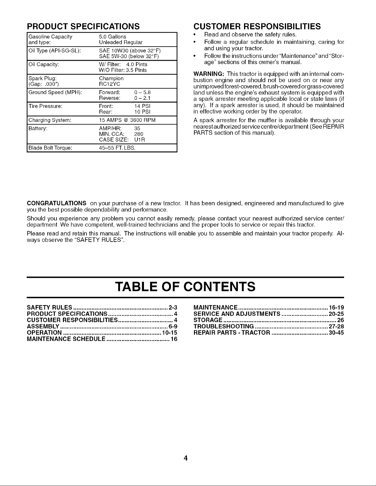
PRODUCT SPECIFICATIONS
Gasoline Capacity 5.0 Gallons
and type: Unleaded Regular
Oil Type (API-SG-SL): SAE 10W30 (above 32°F)
SAE 5W-30 (below 32°F)
Oil Capacity: W/Filter: 4.0 Pints
W/O Filter: 3.5 Pints
Spark Plug: Champion
(Gap: .030") RC12YC
Ground Speed (MPH): Forward: 0 - 5.8
Reverse: 0 - 2.1
Tire Pressure: Front: 14 PSI
Rear: 10 PSI
Charging System: 15 AMPS @ 3600 RPM
Battery: AMP/HR: 35
MIN. CCA: 280
CASE SIZE: U1R
Blade Bolt Torque: 45-55 FT. LBS.
CUSTOMER RESPONSIBILITIES
• Read and observe the safety rules,
• Follow a regular schedule in maintaining, caring for
and using your tractor.
• Follow the instructions under "Maintenance" and "Stor-
age" sections of this owner's manual.
WARNING: This tractor is equipped with an internal com-
bustion engine and should not be used on or near any
unimproved forest-covered, brush-covered orgrass-covered
land unless the engine's exhaust system is equipped with
a spark arrester meeting applicable local or state laws (if
any). If a spark arrester is used, it should be maintained
in effective working order by the operator,
A spark arrester for the muffler is available through your
nearest authorized service centre/department (See REPAIR
PARTS section of this manual),
CONGRATULATIONS on your purchase of a new tractor, It has been designed, engineered and manufactured to give
you the best possible dependability and performance,
Should you experience any problem you cannot easily remedy, please contact your nearest authorized service center/
department We have competent, well-trained technicians and the proper tools to service or repair this tractor,
Please read and retain this manual, The instructions will enable you to assemble and maintain your tractor properly. Al-
ways observe the "SAFETY RULES".
TABLE OF CONTENTS
SAFETY RULES ......................................................... 2-3
PRODUCT SPECIFICATIONS ....................................... 4
CUSTOMER RESPONSIBILITIES ................................. 4
ASSEMBLY ................................................................. 6-9
OPERATION ........................................................... 10-15
MAINTENANCE SCHEDULE ...................................... 16
MAINTENANCE ...................................................... 16-19
SERVICE AND ADJUSTMENTS ............................ 20-25
STORAGE .................................................................... 26
TROUBLESHOOTING ............................................ 27-28
REPAIR PARTS - TRACTOR .................................. 30-45
4
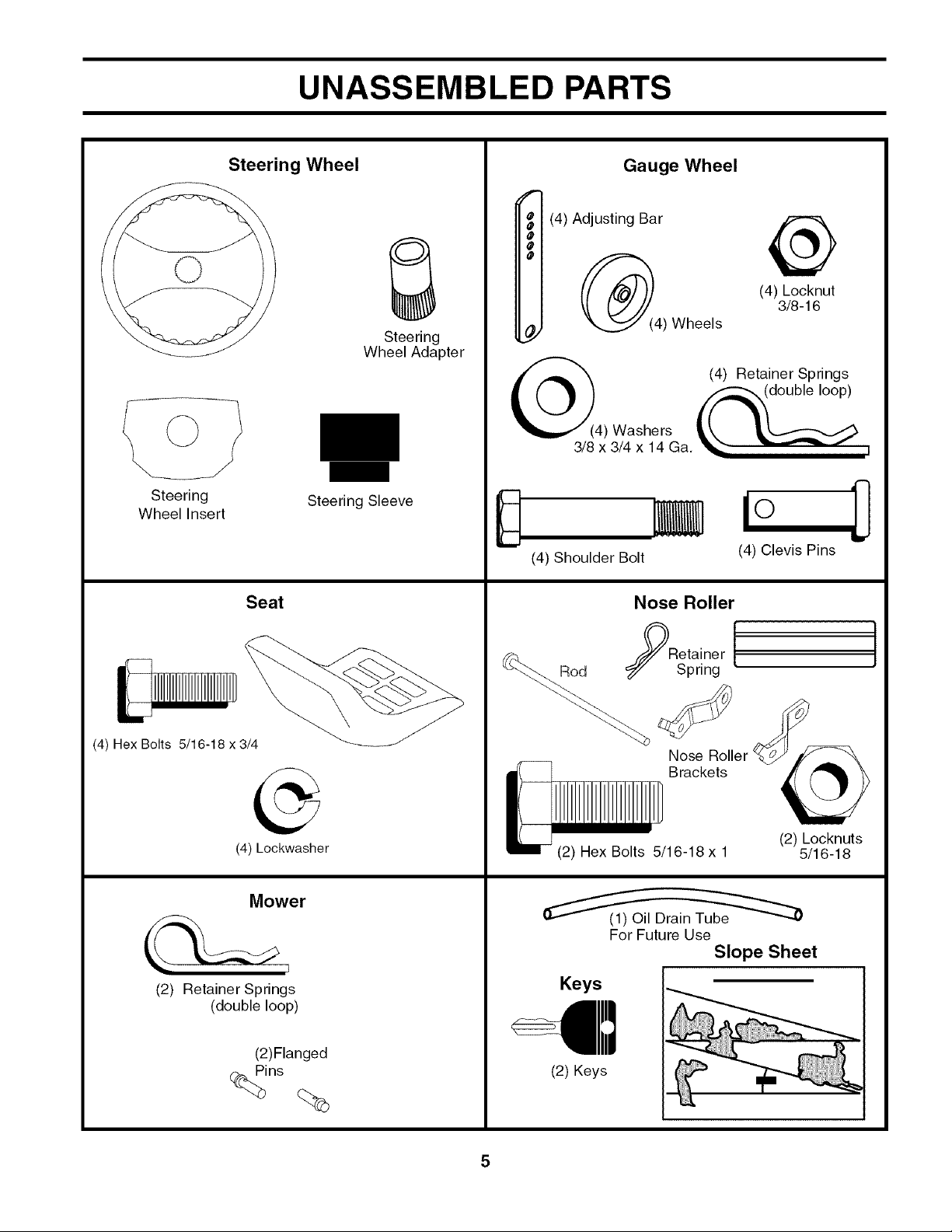
UNASSEMBLED PARTS
Steering
Wheel Insert
Steering Wheel
Steering Sleeve
Seat
Steering
Wheel Adapter
Gauge Wheel
f
• (4) Adjusting Bar
O
O
O
@
(4) Washers
3/8 x 3/4 x 14 Ga.
(4) Shoulder Bolt
Nose Roller
@
(4) Locknut
3/8-16
(4) Wheels
(4) Retainer Springs
(4) Clevis Pins
(4) Hex Bolts 5/16-18 x 3/4
(4) kockwasher
(2) Retainer Springs
(double loop)
Mower
(2)Flanged
Rod
(2) Hex Bolts 5/16-18 x 1
For Future Use
Keys
(2) Keys
Spring [
Nose Roller
Brackets
I
(2) Locknuts
5/16-18
Slope Sheet
ASSEMBLY
Your new tractor has been assembled at the factory with exception of those parts left unassembled for shipping purposes.
To ensure safe and proper operation of your tractor all parts and hardware you assemble must be tightened securely, Use
the correct tools as necessary to insure proper tightness.
TOOLS REQUIRED FOR ASSEMBLY
A socket wrench set will make assembly easier, Standard
wrench sizes are listed.
(1) Pliers (1) Tire pressure gauge
(2) 1/2" wrench (1) Utility knife
(1) 3/4" wrench (1) 3/4" socket w/drive ratchet
(1) 9/16" wrench
When right or left hand is mentioned in this manual, it means
when you are in the operating position (seated behind the
steering wheel),
TO REMOVE TRACTOR FROM
CARTON
UNPACK CARTON
• Remove all accessible loose parts and parts cartons
from carton,
• Cut along dotted lines on all four panels of carton,
Remove end panels and lay side panels flat,
• Remove mower and packing materials,
• Check for any additional loose parts or cartons and
remove.
STEERING
STEERING
SLEEVE
BEFORE REMOVING TRACTOR FROM
SKID
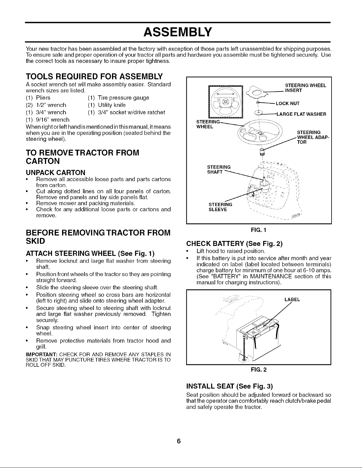
ATTACH STEERING WHEEL (See Fig. 1)
• Remove Iocknut and large flat washer from steering
shaft.
• Position front wheels of the tractor so they are pointing
straight forward.
• Slide the steering sleeve over the steering shaft,
• Position steering wheel so cross bars are horizontal
(left to right) and slide onto steering wheel adapter,
• Secure steering wheel to steering shaft with Iocknut
and large flat washer previously removed. Tighten
securely,
• Snap steering wheel insert into center of steering
wheel,
• Remove protective materials from tractor hood and
grill.
IMPORTANT: CHECK FOR AND REMOVE ANY STAPLES IN
SKID THAT MAY PUNCTURE TIRES WHERE TRACTOR IS TO
ROLLOFF SKID.
FIG. 1
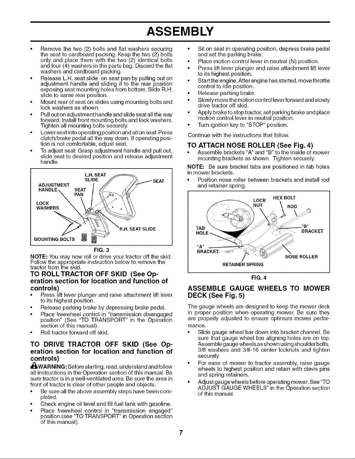
CHECK BATTERY (See Fig. 2)
• Lift hood to raised position.
• If this battery is put into service after month and year
indicated on label (label located between terminals)
charge battery for minimum of one hour at 6-10 amps.
(See "BATTERY" in MAINTENANCE section of this
manual for charging instructions).
--.¢,
..... ", LABEL
FIG. 2
INSTALL SEAT (See Fig. 3)
Seat position should be adjusted forward or backward so
that the operator can comfortably reach clutch/brake pedal
and safely operate the tractor,
6
ASSEMBLY
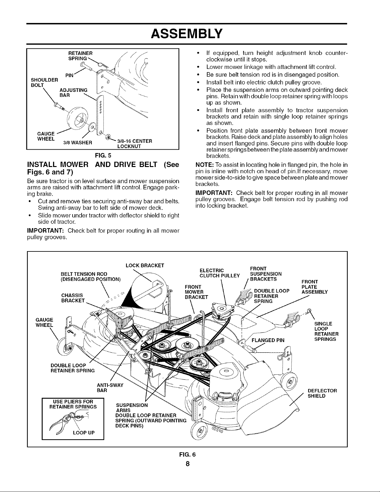
• Remove the two (2) bolts and flat washers securing
the seat to cardboard packing, Keep the two (2) bolts
only and place them with the two (2) identical bolts
and four (4) washers in the parts bag, Discard the flat
washers and cardboard packing.
Release L,H. seat slide on seat pan by pulling out on
adjustment handle and sliding it to the rear position
exposing seat mounting holes from bottom. Slide R,H.
slide to same rear position,
Mount rear of seat on slides using mounting bolts and
lock washers as shown.
Pull out on adjustment handle and slide seat all the way
forward, Install front mounting bolts and lock washers,
Tighten all mounting bolts securely.
Lower seat intooperating position and sit on seat, Press
clutch/brake pedal all the way down, If operating posi-
tion is not comfortable, adjust seat,
To adjust seat: Grasp adjustment handle and pull out,
slide seat to desired position and release adjustment
handle.
L.H. SEAT
SLIDE
__ SEAT
HADJUDSLTEME, NT SEAT
Lw%E", \
X PAN
• Sit on seat in operating position, depress brake pedal
and set the parking brake.
• Place motion control lever in neutral (N) position,
• Press lift lever plunger and raise attachment lift lever
to its highest position.
• Start the engine,After engine has started, move throttle
control to idle position.
• Release parking brake,
• Slowly move the motion control lever forward andslowly
drive tractor off skid.
• Apply brake to stop tractor, set parking brake and place
motion control lever in neutral position,
• Turn ignition key to "STOP" position,
Continue with the instructions that follow,
TO ATTACH NOSE ROLLER (See Fig. 4)
• Assemble brackets "A" and "B" to the inside of mower
mounting brackets as shown. Tighten securely.
NOTE: Be sure bracket tabs are positioned in tab holes
in mower brackets,
• Position nose roller between brackets and install rod
and retainer spring.
LOCK
NUT ROD
HEX BOLT
02521
_R.H. SEAT SLIDE
MOUNTING BOLT'O_S_
FIG. 3
NOTE: You may now rollor drive your tractoroff the skid,
Follow the appropriate instruction below to remove the
tractor from the skid.
TO ROLL TRACTOR OFF SKID (See Op-
eration section for location and function of
controls)
• Press lift lever plunger and raise attachment lift lever
to its highest position,
• Release parking brake by depressing brake pedal.
• Place freewheel control in "transmission disengaged
position" (See "TO TRANSPORT" in the Operation
section of this manual),
• Roll tractor forward off skid,
TO DRIVE TRACTOR OFF SKID (See Op-
eration section for location and function of
controls)
_I, WARNING: Before starting, read, understand and follow
all instructions in the Operation section of this manual, Be
sure tractor is in a well-ventilated area. Be sure the area in
front of tractor is clear of other people and objects,
• Be sure all the above assembly steps have been com-
pleted,
• Check engine oil level and fill fuel tank with gasoline.
• Place freewheel control in "transmission engaged"
position (see "TO TRANSPORT" in Operation section
of this manual),
TAB
RETAINER SPRING
BRACKET
NOSE ROLLER
FIG. 4
ASSEMBLE GAUGE WHEELS TO MOWER
DECK (See Fig. 5)
The gauge wheels are designed to keep the mower deck
in proper position when operating mower, Be sure they
are properly adjusted to ensure optimum mower perfor-
mance,
• Slide gauge wheel bar down into bracket channel, Be
sure that gauge wheel bar aligning holes are on top.
Assemble gauge wheels as shown using shoulder bolts,
3/8 washers and 3/8-16 center Iocknuts and tighten
securely.
• For ease of mower to tractor assembly, raise gauge
wheels to highest position and retain with clevis pins
and spring retainers.
• Adjust gauge wheels before operating mower. See "TO
ADJUST GAUGE WHEELS" in the Operation section
of this manual.
ASSEMBLY
RETAINER •
SHOULDER
BOLT
GAUGE
WHEEL
3/8WASHER
_'_3/8-16CENTER
LOCKNUT
FIG. 5
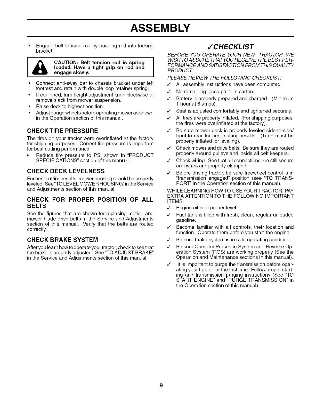
INSTALL MOWER AND DRIVE BELT (See
Figs. 6 and 7)
Be sure tractor is on level surface and mower suspension
arms are raised with attachment lift control Engage park
ing brake
• Cut and remove ties securing antisway bar and belts
Swing antisway bar to left side of mower deck
• Slide mower under tractor with deflector shield to right
side of tractor
IMPORTANT: Check belt for proper routing in all mower
pulley grooves
If equipped turn height adjustment knob counter
clockwise until it stops
• Lower mower linkage with attachment lift control
• Be sure belt tension rod is in disengaged position
• Install belt into electric clutch pulley groove
• Place the suspension arms on outward pointing deck
pins Retain with double loop retainer spring with loops
up as shown
• Install front plate assembly to tractor suspension
brackets and retain with single loop retainer springs
as shown
• Position front plate assembly between front mower
brackets Raise deck and plate assembly to align holes
and insert flanged pins Secure pins with double loop
retainer springs between theplate assembly and mower
brackets
NOTE: To assist in locating hole in flanged pin the hole in
pin is inline with notch on head of pin lf necessary move
mower sidetoside togive space between plate and mower
brackets
IMPORTANT: Check belt for proper routing in all mower
pulley grooves Engage belt tension rod by pushing rod
into locking bracket
(DISENGAGED POSITION)
GAUGE
WHEEL
DOUBLE LOOP
RETAINER SPRING
USE PLIERS FOR
RETAINER SPRINGS
BELTTENSION ROD
CHASSIS _ _
BRACKET
ANTI-SWAY
BAR
LOOP UP
LOCKBRACKET
SUSPENSION
ARMS
DOUBLE LOOP RETAINER
SPRING (OUTWARD POINTING
DECK PINS)
ELECTRIC FRONT
CLUTCH PULLEY SUSPENSION
FRONT
MOWER
BRACKET
BRACKETS
DOUBLE LOOP
] RETAINER
SPRING
FLANGED PIN
FRONT
PLATE
ASSEMBLY
SINGLE
LOOP
RETAINER
SPRINGS
DEFLECTOR
SHIELD
FIG. 6
8
ASSEMBLY
• Engage belt tension rod by pushing rod into locking
bracket.
CAUTION: Belt tension rod is spring I
I&
• Connect anti-sway bar to chassis bracket under left
footrest and retain with double loop retainer spring,
• If equipped, turn height adjustment knob clockwise to
remove slack from mower suspension,
• Raise deck to highest position,
• Adjust gauge wheels before operating mower as shown
in the Operation section of this manual,
loaded, Have a tight grip on rod and
CHECKTIRE PRESSURE
The tires on your tractor were overinflated at the factory
for shipping purposes, Correct tire pressure is important
for best cutting performance.
• Reduce tire pressure to PSI shown in "PRODUCT
SPECIFICATIONS" section of this manual.
CHECK DECK LEVELNESS
For best cutting results, mower housing should be properly
leveled, See "TOLEVEL MOWER HOUSING" inthe Service
and Adjustments section of this manual,
CHECK FOR PROPER POSITION OF ALL
BELTS
See the figures that are shown for replacing motion and
mower blade drive belts in the Service and Adjustments
section of this manual. Verify that the belts are routed
correctly.
CHECK BRAKE SYSTEM
After you learn how toope rateyou rtractor, check to see that
the brake is properly adjusted, See "TO ADJUST BRAKE"
in the Service and Adjustments section of this manual.
,/'CHECKLIST
BEFORE YOU OPERATE YOUR NEW TRACTOR, WE
I
WISH TOASSURE THATYOU RECEIVE THE BEST PER-
FORMANCE AND SATISFACTION FROM THIS QUALITY
PRODUCT.
Iengage slowly,
PLEASE REVIEW THE FOLLOWING CHECKLIST:
,/ All assembly instructions have been completed.
,/ No remaining loose parts in carton.
,/ Battery is properly prepared and charged. (Minimum
1 hour at 6 amps).
,/ Seat is adjusted comfortably and tightened securely.
,/ All tires are properly inflated. (For shipping purposes,
the tires were overinflated at the factory).
,/ Be sure mower deck is properly leveled side-to-side/
front-to-rear for best cutting results. (Tires must be
properly inflated for leveling).
,/ Check mower and drive belts. Be sure they are routed
properly around pulleys and inside all belt keepers.
,/ Check wiring. See that all connections are still secure
and wires are properly clamped.
,/ Before driving tractor, be sure freewheel control is in
"transmission engaged" position (see "TO TRANS-
PORT" in the Operation section of this manual).
WHILE LEARNING HOWTO USEYOURTRACTOR, PAY
EXTRA ATTENTION TOTHE FOLLOWING IMPORTANT
ITEMS:
,/ Engine oil is at proper level.
,/ Fuel tank is filled with fresh, clean, regular unleaded
gasoline.
,/ Become familiar with all controls, their location and
function. Operate them before you start the engine.
,/ Be sure brake system is in safe operating condition.
,/ Be sure Operator Presence System and Reverse Op-
eration System (ROS) are working properly (See the
Operation and Maintenance sections in this manual).
,/ It is important to purge the transmission before oper-
ating your tractor for the first time. Follow proper start-
ing and transmission purging instructions (See "TO
START ENGINE" and "PURGE TRANSMISSION" in
the Operation section of this manual).
OPERATION
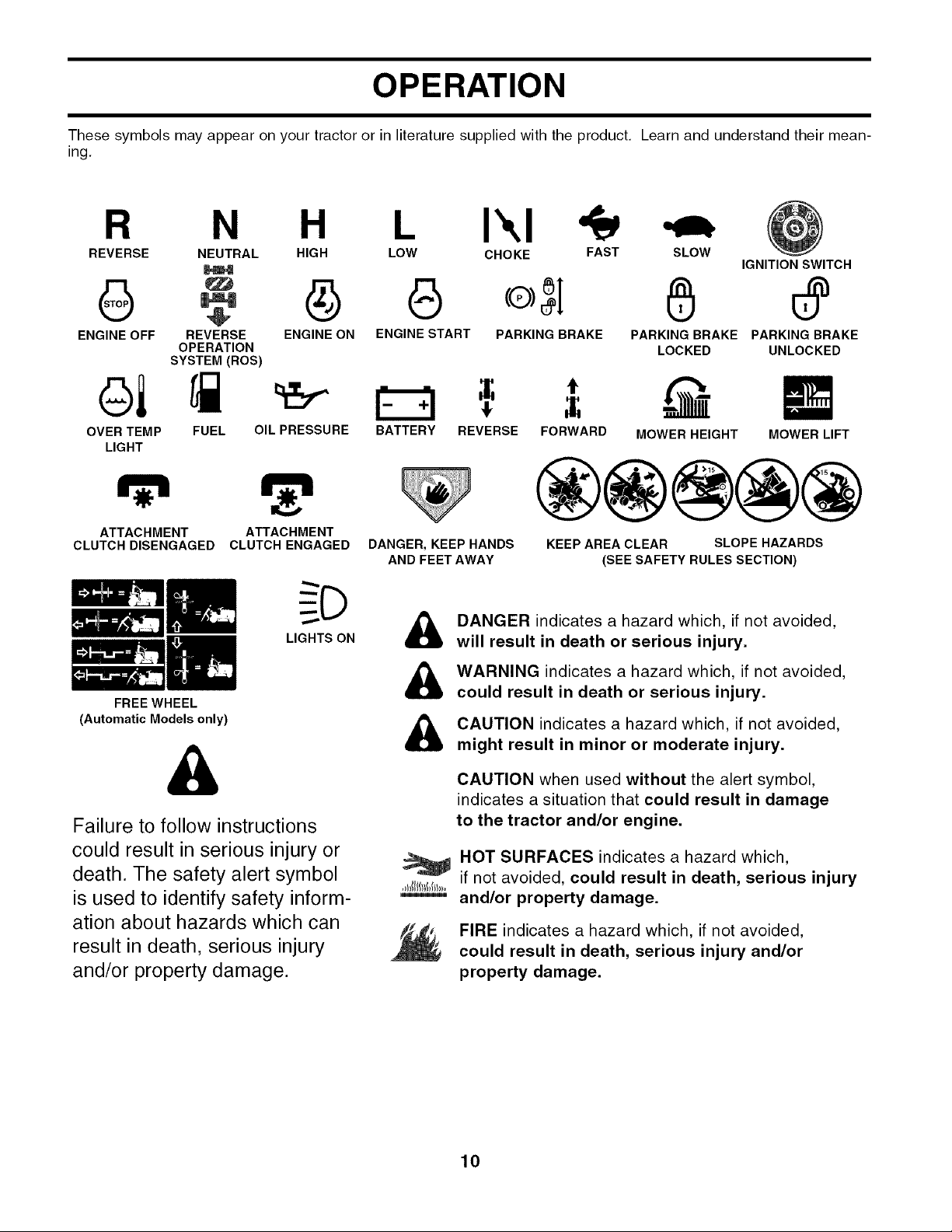
These symbols may appear on your tractor or in literature supplied with the product, Learn and understand their mean-
ing.
R N L
REVERSE NEUTRAL HIGH LOW
G G
ENGINE OFF REVERSE ENGINE ON ENGINE START
ol
OVER TEMP
LIGHT
ATTACHMENT
CLUTCH DISENGAGED
FREE WHEEL
(Automatic Models only)
OPERATION
SYSTEM (ROS)
FUEL OIL PRESSURE
ATTACHMENT
CLUTCH ENGAGED
LIGHTS ON
BATTERY REVERSE FORWARD MOWER HEIGHT MOWER LIFT
DANGER, KEEP HANDS
AND FEET AWAY
&
I',,I
CHOKE FAST SLOW
PARKING BRAKE PARKING BRAKE PARKING BRAKE
LOCKED UNLOCKED
t
KEEP AREA CLEAR SLOPE HAZARDS
(SEE SAFETY RULES SECTION)
DANGER indicates a hazard which, if not avoided,
will result in death or serious injury.
WARNING indicates a hazard which, if not avoided,
could result in death or serious injury.
CAUTION indicates a hazard which, if not avoided,
might result in minor or moderate injury.
IGNITION SWITCH
&
Failure to follow instructions
could result in serious injury or
death. The safety alert symbol
is used to identify safety inform-
ation about hazards which can
result in death, serious injury
and/or property damage.
CAUTION when used without the alert symbol,
indicates a situation that could result in damage
to the tractor and/or engine.
HOT SURFACES indicates a hazard which,
if not avoided, could result in death, serious injury
and/or property damage.
FIRE indicates a hazard which, if not avoided,
could result in death, serious injury and/or
property damage.
10

OPERATION
KNOW YOUR TRACTOR
READ THIS OWNER'S MANUAL AND SAFETY RULES BEFORE OPERATING YOUR TRACTOR.
Compare the illustrations with your tractor to familiarize yourself with the location of various controls and adjustments,
Save this manual for future reference,
MOTION DRIVE
BELTTENSION
HANDLE
FREEWHEEL
THROTTLE CONTROL
CHOKE
CONTROL_
BRAKE PEDAL
AMMETER IGNITION ROS "ON" POSITION
SWITCH ATTACHMENT
LIGHT SWITCH
HEIGHT
ADJUSTMENT
KNOB
HOURMETER
CLUTCH SWITCH
PLUNGER
LIFT LEVER
PARKING
BRAKE LEVER
MOTION
CONTROL
LEVER
2851
LEVER
Our tractors conform to the safety standards of the American National Standards Institute,
AMMETER - Indicates battery charging(+) or discharg-
ing(-).
ATTACHMENT CLUTCH SWITCH - Used toengage mower
blades or other attachments mounted to your tractor,
BRAKE PEDAL - Used for braking the tractor and starting
the engine,
CHOKE CONTROL - Used when starting a cold engine.
FREEWHEEL CONTROL - Disengages transmission for
pushing or slowly towing the tractor with the engine off.
HEIGHT ADJUSTMENT KNOB - Used to adjust the mower
height,
HOURMETER - Indicates hours of operation,
IGNITION SWITCH - Used to start and stop the engine,
LIFT LEVER - Used to raise and lower mower deck or
other attachments mounted to your tractor.
FIG. 7
LIFT LEVER PLUNGER - Used to release attachment lift
lever when changing its position,
LIGHT SWITCH - Turns the headlights on and off,
MOTION CONTROL LEVER - Selects the speed and
direction of tractor.
MOTION DRIVE BELT TENSION HANDLE - Used when
changing motion drive belt and, ifnecessary, starting engine
under extremely cold conditions,
PARKING BRAKE LEVER - Locks brake pedal into the
brake position,
REVERSE OPERATION SYSTEM (ROS)"ON" POSI-
TION - Allows operation of mower deck or other powered
attachment while in reverse.
THROTTLE CONTROL - Used to control engine speed.
11
OPERATION
The operation of any tractor can result in foreign objects thrown into the eyes, which
can result in severe eye damage. Always wear safety glasses or eye shields while op-
erating your tractor or performing any adjustments or repairs. We recommend a wide
vision safety mask over spectacles or standard safety glasses.
HOW TO USE YOUR TRACTOR
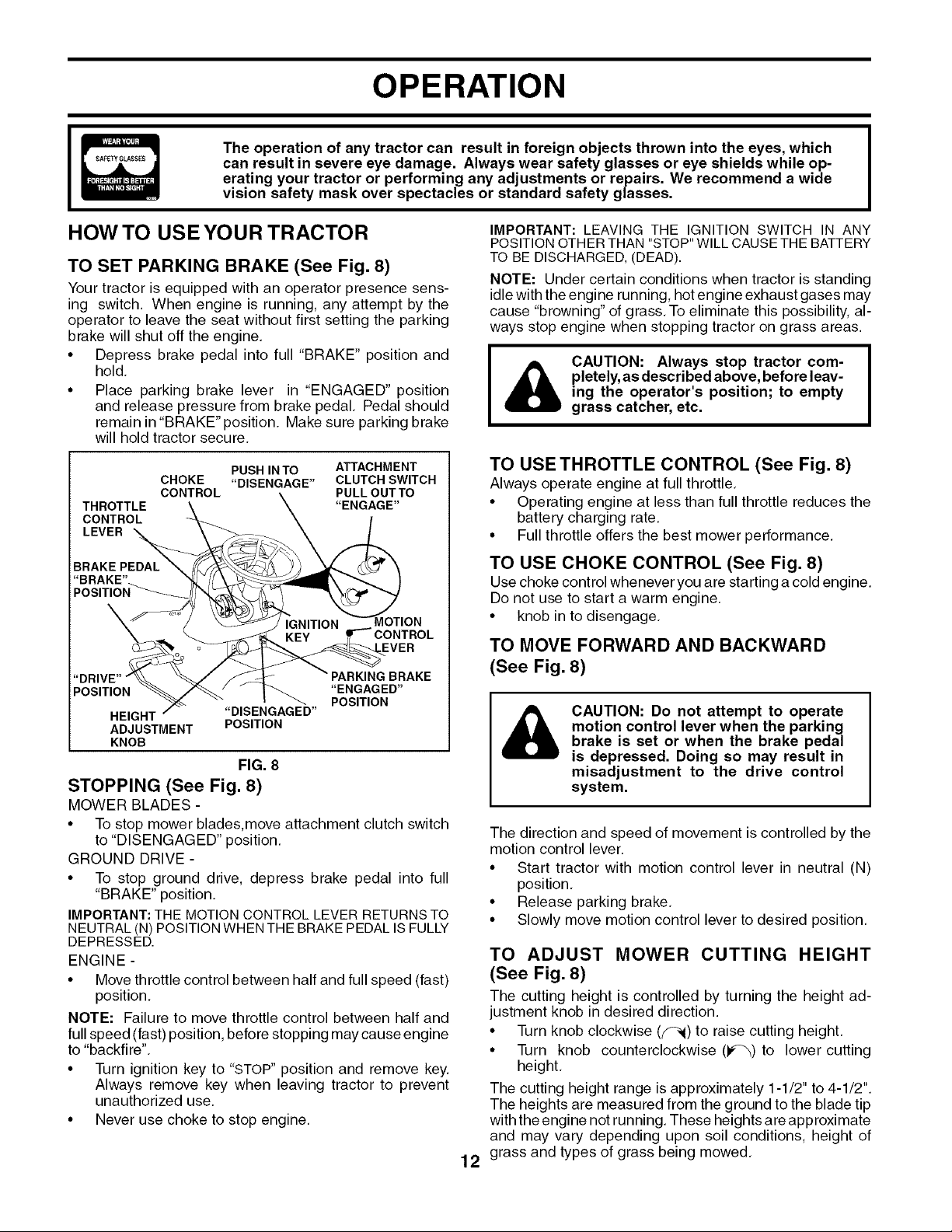
TO SET PARKING BRAKE (See Fig. 8)
Your tractor is equipped with an operator presence sens
ing switch When engine is running, any attempt by the
operator to leave the seat without first setting the parking
brake will shut off the engine
• Depress brake pedal into full "BRAKE" position and
hold
• Place parking brake lever in "ENGAGED" position
and release pressure from brake pedal Pedal should
remain in "BRAKE" position Make sure parking brake
will hold tractor secure
CHOKE "DISENGAGE" CLUTCH SWITCH
THROTTLE
CONTROL
LEVER
"DRIVE"
POSITION
HEIGHT "DISENGAGED"
ADJUSTMENT POSITION
KNOB
CONTROL PULL OUT TO
STOPPING (See Fig. 8)
MOWER BLADES
• To stop mower blades,move attachment clutch switch
to "DISENGAGED' position
GROUND DRIVE
• To stop ground drive, depress brake pedal into full
"BRAKE' position
IMPORTANT: THE MOTION CONTROL LEVER RETURNS TO
NEUTRAL (N) POSITION WHEN THE BRAKE PEDAL IS FULLY
DEPRESSED
ENGINE
• Move throttle control between half and full speed (fast)
position
NOTE: Failure to move throttle control between half and
full speed (fast) position, before stopping may cause engine
to "backfire"
• Turn ignition key to "STOP" position and remove key
Always remove key when leaving tractor to prevent
unauthorized use
• Never use choke to stop engine
PUSH IN TO ATTACHMENT
"ENGAGE"
_IOTION
"ENGAGED"
POSITION
FIG. 8
IMPORTANT: LEAVING THE IGNITION SWITCH IN ANY
POSITION OTHER THAN STOP' WILL CAUSE THE BATTERY
TO BE DISCHARGED, (DEAD)
NOTE: Under certain conditions when tractor is standing
idle with the engine running, hot engine exhaust gases may
cause "browning'of grass To eliminate this possibility, al
ways stop engine when stopping tractor on grass areas
pletely, as described above, before leav-
_11 AUTION: Always stop tractor com-
ing the operator's position; to empty
grass catcher, etc.
TO USE THROTTLE CONTROL (See Fig. 8)
Always operate engine at full throttle
• Operating engine at less than full throttle reduces the
battery charging rate
• Full throttle offers the best mower performance
TO USE CHOKE CONTROL (See Fig 8)
Use choke control whenever you are starting a cold engine
Do not use to start a warm engine
• knob in to disengage
TO MOVE FORWARD AND BACKWARD
(See Fig. 8)
CAUTION: Do not attempt to operate
motion control lever when the parking
brake is set or when the brake pedal
is depressed. Doing so may result in
misadjustment to the drive control
system.
The direction and speed of movement is controlled by the
motion control lever
• Start tractor with motion control lever in neutral (N)
position
• Release parking brake
• Slowly move motion control lever to desired position
TO ADJUST MOWER CUTTING HEIGHT
(See Fig. 8)
The cutting height is controlled by turning the height ad
justment knob in desired direction
• Turn knob clockwise (Y_i) to raise cutting height
• Turn knob counterclockwise (_)to lower cutting
height
The cutting height range is approximately 11/2 to 41/2
The heights are measured from the ground to the blade tip
with the engine not running These heights are approximate
and may vary depending upon soil conditions, height of
grass and types of grass being mowed
12
OPERATION
• The average lawn should be cut to approximately 2-1/2
inches during the cool season and to over 3 inches
during hot months, For healthier and better looking
lawns, mow often and after moderate growth,
• For best cutting performance, grass over 6 inches
in height should be mowed twice, Make the first cut
relatively high; the second to desired height.
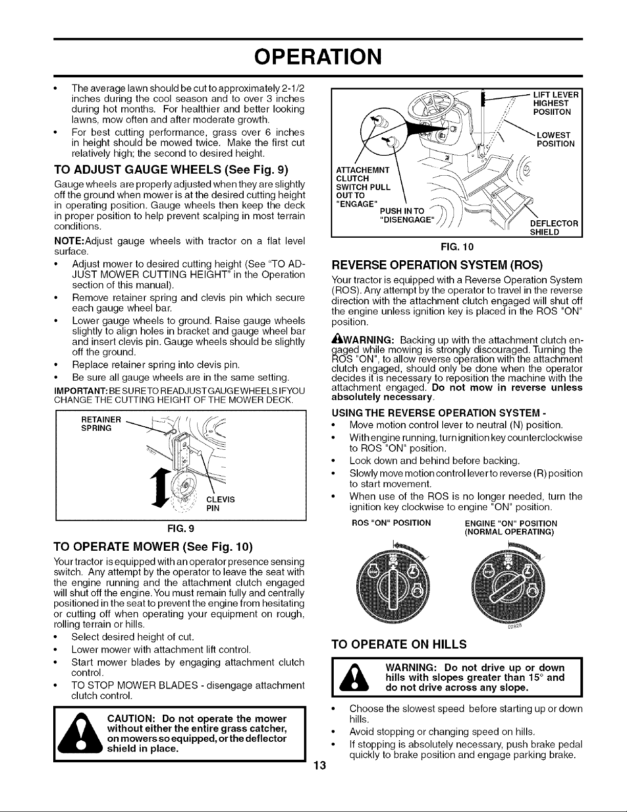
TO ADJUST GAUGE WHEELS (See Fig. 9)
Gauge wheels are properly adjusted when they are slightly
off the ground when mower is at the desired cutting height
in operating position, Gauge wheels then keep the deck
in proper position to help prevent scalping in most terrain
conditions.
NOTE:Adjust gauge wheels with tractor on a flat level
surface.
• Adjust mower to desired cutting height (See "TO AD-
JUST MOWER CUTTING HEIGHT" in the Operation
section of this manual),
• Remove retainer spring and clevis pin which secure
each gauge wheel bar.
• Lower gauge wheels to ground, Raise gauge wheels
slightly to align holes in bracket and gauge wheel bar
and insert clevis pin, Gauge wheels should be slightly
off the ground,
• Replace retainer spring into clevis pin.
• Be sure all gauge wheels are in the same setting,
IMPORTANT:BESURETOREADJUSTGAUGEWHEELSIFYOU
CHANGETHE CUTTING HEIGHTOFTHE MOWER DECK.
RETAINER
SPRING
CLEVIS
PIN
FIG. 9
TO OPERATE MOWER (See Fig. 10)
Your tractor is equipped with an operator presence sensing
switch. Any attempt by the operator to leave the seat with
the engine running and the attachment clutch engaged
will shut off the engine.You must remain fully and centrally
positioned in the seat to prevent the engine from hesitating
or cutting off when operating your equipment on rough,
rolling terrain or hills,
• Select desired height of cut,
• Lower mower with attachment lift control,
• Start mower blades by engaging attachment clutch
control.
• TO STOP MOWER BLADES - disengage attachment
clutch control.
CAUTION: Do not operate the mower
without either the entire grass catcher,
on mowers so equipped, or thedeflector
shield in place.
LIFT LEVER
,,_, HIGHEST
i-" POSIITON
";;;'_ LOWEST
POSITION
ATTACHEMNT
CLUTCH
SWITCH PULL
OUTTO
"ENGAGE"
PUSH IN TO
"DISENGAGE"
DEFLECTOR
SHIELD
FIG. 10
REVERSE OPERATION SYSTEM (ROS)
Your tractor is equipped with a Reverse Operation System
(ROS). Any attempt by the operator to travel in the reverse
direction with the attachment clutch engaged will shut off
the engine unless ignition key is placed in the ROS "ON"
position.
_WARNING: Backing up with the attachment clutch en-
gaged while mowing is strongly discouraged. Turning the
ROS "ON", to allow reverse operation with the attachment
clutch engaged, should only be done when the operator
decides it is necessary to reposition the machine with the
attachment engaged, Do not mow in reverse unless
absolutely necessary.
USING THE REVERSE OPERATION SYSTEM -
• Move motion control lever to neutral (N) position,
• With engine running, turn ignition keycounterclockwise
to ROS "ON" position.
• Look down and behind before backing.
• Slowly move motion control lever to reverse (R) position
to start movement,
• When use of the ROS is no longer needed, turn the
ignition key clockwise to engine "ON" position,
ROS "ON" POSITION ENGINE "ON" POSITION
(NORMAL OPERATING)
TO OPERATE ON HILLS
i i_) WARNING: Do not drive up or down I
• Choose the slowest speed before starting up or down
hills,
• Avoid stopping or changing speed on hills,
• If stopping is absolutely necessary, push brake pedal
quickly to brake position and engage parking brake.
13
hills with slopes greater than 15° and
do not drive across any slope.
=
I
OPERATION
IMPORTANT: THE MOTION CONTROL LEVER RETURNS
TO NEUTRAL (N) POSITIONWHEN THE BRAKE PEDAL IS
FULLYDEPRESSED.
• To restart movement, slowly release parking brake and
brake pedal,
• Slowly move motion control lever to slowest setting,
• Make all turns slowly.
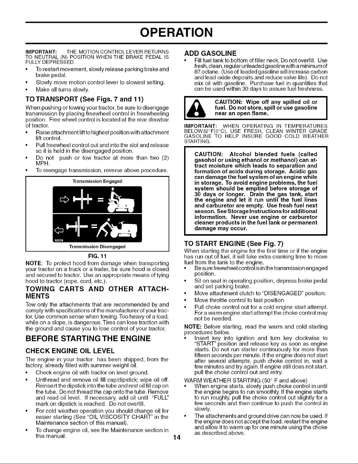
TO TRANSPORT (See Figs. 7 and 11)
When pushing or towing your tractor, be sure to disengage
transmission by placing freewheel control in freewheeling
position. Free wheel control is located at the rear drawbar
of tractor,
• Raise attachment liftto highest position with attachment
lift control,
• Pull freewheel control out and into the slot and release
so it is held in the disengaged position,
• Do not push or tow tractor at more than two (2)
MPH.
• To reengage transmission, reverse above procedure,
Transmission Engaged
ADD GASOLINE
• Fillfuel tank to bottom of filler neck. Do not overfill, Use
fresh,clean, regular unleadedgasoline with aminimum of
87 octane, (Use of leaded gasoline will increase carbon
and lead oxide deposits and reduce valve life), Do not
mix oil with gasoline, Purchase fuel in quantities that
can be used within 30 days to assure fuel freshness.
I& CAUTION: Wipe off any spilled oil or I
IMPORTANT: WHEN OPERATING IN TEMPERATURES
BELOW32°F(0°C), USE FRESH, CLEAN WINTER GRADE
GASOLINE TO HELP INSURE GOOD COLD WEATHER
STARTING.
CAUTION: Alcohol blended fuels (called
gasohol or using ethanol or methanol) can at-
tract moisture which leads to separation and
formation of acids during storage. Acidic gas
can damage the fuel system of an engine while
in storage. To avoid engine problems, the fuel
system should be emptied before storage of
30 days or longer. Drain the gas tank, start
the engine and let it run until the fuel lines
and carburetor are empty. Use fresh fuel next
season. See Storage Instructions for additional
information. Never use engine or carburetor
cleaner products in the fuel tank or permanent
damage may occur.
fuel. Do not store, spill or use gasoline
near an open flame,
I
Transmission Disengaged
FIG. 11
NOTE: To protect hood from damage when transporting
your tractor on a truck or a trailer, be sure hood is closed
and secured to tractor. Use an appropriate means of tying
hood to tractor (rope, cord, etc,).
TOWING CARTS AND OTHER ATTACH-
MENTS
Tow only the attachments that are recommended by and
comply with specifications of the manufacturer ofyour trac-
tor, Use common sense when towing. Too heavy of a load,
while on aslope, is dangerous.Tires can lose traction with
the ground and cause you to lose control of your tractor,
BEFORE STARTING THE ENGINE
CHECK ENGINE OIL LEVEL
The engine in your tractor has been shipped, from the
factory, already filled with summer weight oil,
• Check engine oil with tractor on level ground.
• Unthread and remove oil fill cap/dipstick; wipe oil off,
Reinsert the dipstick into the tube and rest oil fill cap on
the tube, Do not thread the cap onto the tube, Remove
and read oil level, If necessary, add oil until "FULl"
mark on dipstick is reached, Do not overfill,
• For cold weather operation you should change oil for
easier starting (See "OIL VISCOSITY CHART" in the
Maintenance section of this manual).
• To change engine oil, see the Maintenance section in
this manual,
TO START ENGINE (See Fig. 7)
When starting the engine for the first time or ifthe engine
has run out of fuel, it will take extra cranking time to move
fuel from the tank to the engine.
• Besure freewheel control isinthe transmission engaged
position,
• Sit on seat in operating position, depress brake pedal
and set parking brake,
• Move attachment clutch to "DISENGAGED" position.
• Move throttle control to fast position
• Pull choke control out for a cold engine start attempt,
Fora warm engine start attempt the choke control may
not be needed.
NOTE: Before starting, read the warm and cold starting
procedures below,
• Insert key into ignition and turn key clockwise to
"START" position and release key as soon as engine
starts, Do not run starter continuously for more than
fifteen seconds per minute. If the engine does not start
after several attempts, push choke control in, wait a
few minutes and try again, If engine still does not start,
pull the choke control out and retry.
WARM WEATHER STARTING (50° F and above)
• When engine starts, slowly push choke control in until
the engine begins to run smoothly. If the engine starts
to run roughly, pull the choke control out slightly for a
few seconds and then continue to push the control in
slowly,
• The attachments and ground drive can now be used, If
the engine does not accept the load, restart the engine
and allow it to warm up for one minute using the choke
as described above,
14

OPERATION
COLD WEATHER STARTING (50° F and below)
• When engine starts, slowly push choke control in until
the engine begins to run smoothly. Continue to push
the choke control in small steps allowing the engine to
accept small changes in speed and load, until thechoke
control is fully in. If the engine starts to run roughly, pull
the choke control out slightly for a few seconds and
then continue to push the control in slowly. This may
require anengine warm-up period from several seconds
to several minutes, depending on the temperature,
NOTE: Inextreme cold conditions, ifengine will not start,you
may need to disengage the motion drive belt as follows:
• Be sure parking brake is engaged.
• Remove retainer spring from the drive belt tension
handle to relieve belt tension,
• Start engine and allow it to warm up for three (3) min-
utes,
• Shut-off engine and engage parking brake.
• Engage drive belt tension handle and replace the
retainer spring.
AUTOMATIC TRANSMISSION WARM UP
• Before driving the unit incold weather, the transmission
should be warmed up as follows:
• Be sure the tractor is on level ground.
• Place the motion control lever in neutral,
Release the parking brake and let the brake slowly
return to operating position,
• Allow one minute for transmission to warm up,
This can be done during the engine warm up
period,
• The attachmentscan be usedduring the engine warm-up
period after the transmission has been warmed up and
may require the choke control be pulled out slightly.
NOTE: If at a high altitude (above 3000 feet) or in cold
temperatures (below 32 F) the carburetor fuel mixture may
need to be adjusted for best engine performance. See "TO
ADJUST CARBURETOR" in the Service and Adjustments
section of this manual,
PURGE TRANSMISSION
• Move motion control lever to full forward position and
hold for five (5) seconds. Move lever to full reverse
position and hold for five (5) seconds, Repeat this
procedure three (3) times,
NOTE: During this procedure there will be no movement
of drive wheels, The air is being removed from hydraulic
drive system,
• Move motion control lever to neutral (N) position. Shut-
off engine and set parking brake,
• Engage transmission by placing freewheel control in
driving position (See "TO TRANSPORT" inthis section
of manual).
• Sitting in the tractor seat, start engine, After the engine
is running, move throttle control to half (1/2) speed.
Disengage parking brake,
• Slowly movemotion control lever forward, afterthe tractor
moves approximately five (5) feet, slowly move motion
control lever to reverse position. After the tractor moves
approximately five (5) feet return the motion control lever
to the neutral (N) position. Repeat this procedure with
the motion control lever three (3) times,
• Your tractor is now purged and now ready for normal
operation.
MOWING TIPS
• Tire chains cannot be used when the mower housing
is attached to tractor,
• Mower should be properly leveled for best mowing per-
formance, See "TO LEVEL MOWER HOUSING" in the
Service and Adjustments section of this manual.
• The left hand side of mower should be used for trim-
ming,
• Drive so that clippings are discharged onto the area
that has been cut, Have the cut area to the right of
the tractor. This will result in a more even distribution
of clippings and more uniform cutting,
• Whenmowinglargeareas,startbyturningtothe rightsothat
clippingswilldischargeawayfromshrubs,fences,driveways,
etc. Afterone ortwo rounds,mow intheopposite direction
making left handturns untilfinished (See Fig, 12),
f
I& CAUTION: Never engage or disengage I
To ensure proper operation and performance, it is recom-
mended that the transmission be purged before operating
tractor for the first time, This procedure will remove any
trapped air inside the transmission which may have de-
veloped during shipping of your tractor,
IMPORTANT: SHOULD YOUR TRANSMISSION REQUIRE
REMOVAL FOR SERVICE OR REPLACEMENT, IT SHOULD
BE PURGEDAFTERREINSTALLATIONBEFOREOPERATING
THE TRACTOR.
• Place tractor safely on level surface with engine off and
parking brake set.
• Disengage transmission by placing freewheel control
infreewheeling position (See "TOTRANSPORT" in this
section of manual),
• Sitting in the tractor seat, start engine, After the en-
gine is running, move throttle control to slow position,
Disengage parking brake
freewheel lever while the engine is run-
ning.
1
00272
FIG. 12
• If grass is extremely tall, it should be mowed twice to
reduce load and possible fire hazard from dried clip-
pings. Make first cut relatively high; the second to the
desired height,
• Do not mow grass when it is wet, Wet grass will plug
mower and leave undesirable clumps, Allow grass to
dry before mowing,
• Always operate engine at full throttle when mow-
ing to assure better mowing performance and proper
discharge of material. Regulate ground speed by se-
lecting a low enough gear to give the mower cutting
performance as well as the quality of cut desired,
• When operating attachments, select a ground speed
that will suit the terrain and give best performance of
15
the attachment being used,
 Loading...