

Husqvarna 8524STE User Manual
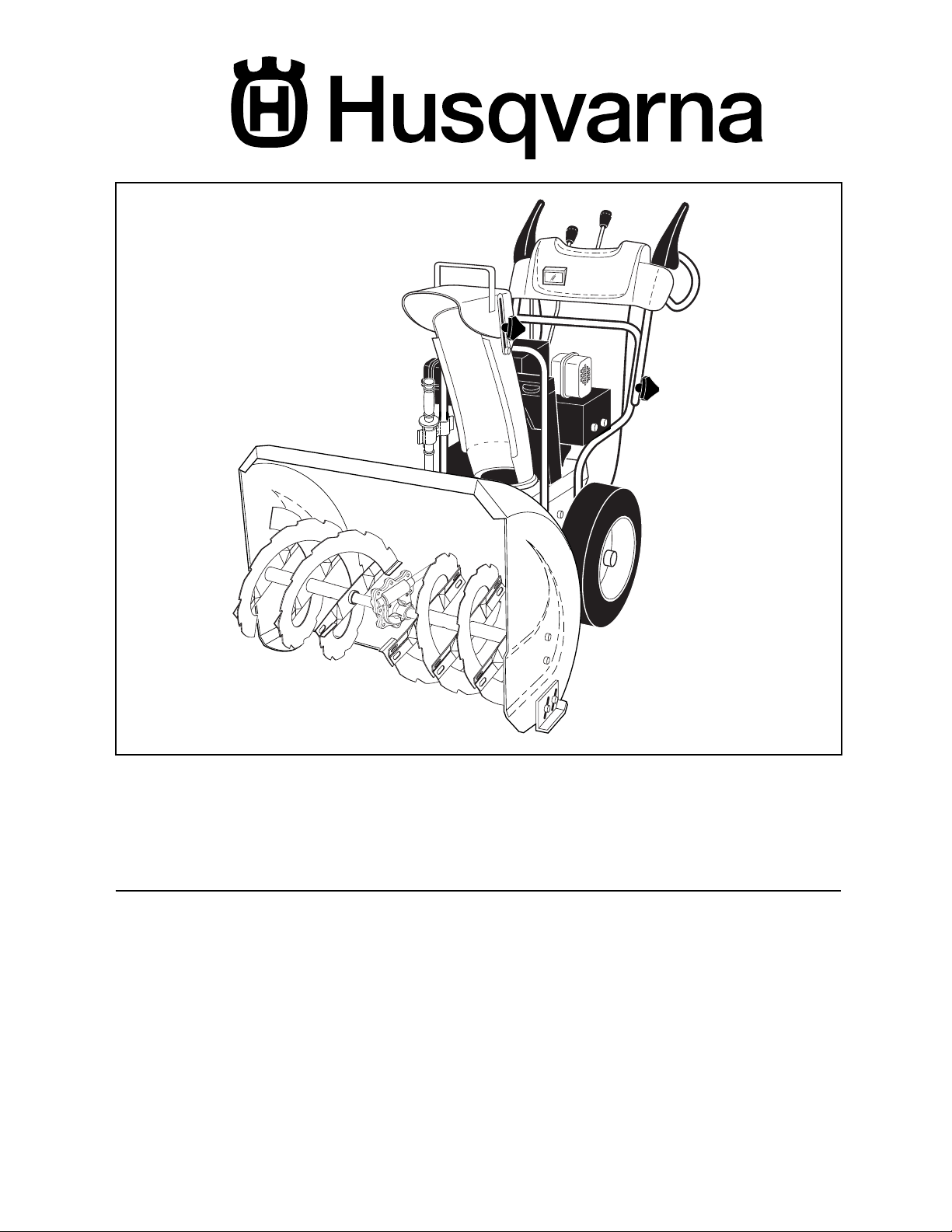
8524STE
Owner's Manual
SAFETY RULES
Safe Operation Practices for Snow Throwers
IMPORTANT: This machine is capable of amputating hands and feet and throwing objects. Failure to observe the following
safety instructions could result in serious injury or death.
Look for this symbol to point out im por tant safety precautions. It means
CAUTION!!! BE COME ALERT!!! YOUR
SAFE TY IS IN VOLVED.
WARNING: Always disconnect spark
plug wire and place it where it can not
con tact plug in order to pre vent ac ci den tal start ing when setting up, trans port ing, ad just ing or making re pairs.
WARNING: This snow thrower is for
use on sidewalks, driveways and other
ground level surfaces. Caution should
be exercised while using on sloping
surfaces. Do not use snow thrower on
surfaces above ground level such as
roofs of residences, garages, porch es
or other such structures or buildings.
WARNING: Snow throwers have ex posed rotating parts, which can cause
severe injury from contact, or from material thrown from the discharge chute.
Keep the area of operation clear of all
persons, small children and pets at all
times including startup.
CAUTION: Muffl er and other engine
parts become extremely hot during
operation and remain hot after engine
has stopped. To avoid severe burns on
contact, stay away from these areas.
WARNING: Engine exhaust, some of
its con stit u ents, and certain vehicle
com po nents contain or emit chem icals known to the State of Cal i for nia
to cause can cer and birth defects or
oth er re pro duc tive harm.
TRAINING
• Read the operating and service instruction manual
care ful ly. Be thoroughly familiar with the controls and
the proper use of the equipment. Know how to stop the
unit and disengage the controls quickly.
• Never allow children to operate the equipment. Never
allow adults to operate the equipment without proper
instruction.
• Keep the area of operation clear of all persons, par tic u lar ly small children and pets.
• Exercise caution to avoid slipping or falling especially
when operating in reverse.
PREPARATION
• Remove foreign objects. Thoroughly inspect the area
where the equip ment is to be used and remove all
doormats, sleds, boards, wires, rocks & landscaping.
• Disengage all clutches before starting engine (mo tor).
• Do not operate the equipment without wearing ad e quate winter outer garments. Avoid loose, dangling
clothing, such as scarves, which can get caught in
rotating parts. Wear footwear that will improve footing
on slippery surfaces.
• Handle fuel with care; it is highly fl ammable.
- Never smoke while refueling.
- Use an approved fuel container.
- Never remove fuel tank cap or add fuel to a running
engine (motor) or hot engine (motor).
- Fill fuel tank outdoors with extreme care. Never fi ll
fuel tank indoors.
- Replace fuel cap securely and wipe up spilled
fuel.
- Never store fuel or snow thrower with fuel in the
tank inside of a building where fumes may reach
an open fl ame or spark.
- Check fuel supply before each use, allowing space
for expansion as the heat of the engine (motor)
and/or sun cause fuel to expand.
STATIC ELECTRICITY HAZARD -
- Never fi ll containers inside a vehicle or on a truck
or trailer bed with a plastic liner. Always place
con tain ers on the ground, away from your vehicle
before fi lling.
- When practical, remove gas-powered equipment
from the truck or trailer and refuel it on the ground.
If this is not possible, then refuel such equipment
on a trailer with a portable container, rather than
from a gasoline dispenser nozzle.
- Keep the nozzle in contact with the rim of the fuel
tankopening at all times, until re fu el ing is complete.
Do not use a nozzle lock-open device.
- If fuel is spilled on clothing, change clothing im-
me di ate ly.
• For all units with electric starting motors use electric
starting ex ten sion cords certifi ed CSA/UL. Use only
with a receptacle that has been installed in accordance
with local inspection authorities.
• If snow thrower must be operated over gravel surface,
use extra caution and be sure skid plates are adjusted
to lowest (highest scraper clear ance) position.
• Never attempt to make any ad just ments while the
engine (motor) is running (except when specifi cally
rec om mend ed by manufacturer).
• Let engine (motor) and snow thrower adjust to outdoor
temperatures before starting to clear snow.
• Always wear safety glasses or eye shields during operation or while performing an adjustment or repair to
protect eyes from foreign objects that may be thrown
from the snow thrower.
OPERATION
• Do not operate this machine if you are under the infl uence of alcohol or taking drugs or other medication
which can cause drowsiness or affect your ability to
operate this ma chine.
• Do not use this machine if you are mentally or phys i cal ly
unable to operate this machine safely.
2
• Do not put hands or feet near or under rotating parts.
Keep clear of the discharge opening and front auger
area at all times.
• Exercise extreme caution when op er at ing on or cross ing gravel drives, walks or roads. Stay alert for hidden
hazards or traffi c.
• After striking a foreign object, stop the engine (motor),
remove wire from the spark plug, thoroughly in spect
snow thrower for any damage, and repair the damage
before restarting and operating the snow thrower.
• If the unit should start to vibrate ab nor mal ly, stop the
engine (motor) and check immediately for the cause.
Vibration is generally a warning of trouble.
• Stop the engine (motor) whenever you leave the op er at ing position, before unclogging the auger/impeller
housing or discharge chute and when making any
repairs, ad just ments, or in spec tions.
• When cleaning, repairing, or in spect ing, make certain
all controls are disengaged and the auger/impeller and
all moving parts have stopped. Disconnect the spark
plug wire and keep the wire away from the spark plug
to prevent accidental starting.
• Take all possible precautions when leaving the snow
thrower unattended. Disengage the auger/impeller, stop
engine (motor), and remove key.
• Do not run the engine (mo tor) in doors, except when
starting the engine (mo tor) and for transporting the
snow thrower in or out of the building. Open the outside
doors.
WARNING: Exhaust fumes are dan ger ous (con tain ing CAR BON MONOXIDE, an ODOR LESS and DEAD LY GAS).
• Do not clear snow across the face of slopes. Exercise
extreme caution when changing direction on slopes.
Do not attempt to clear steep slopes.
• Never operate the snow thrower without proper guards,
plates or other safety protective devices in place.
• Never operate the snow thrower near glass en clo sures, automobiles, window wells, drop–offs, and the
like without proper adjustment of the snow discharge
angle. Keep children and pets away.
• Do not overload the machine capacity by attempting
to clear snow at too fast a rate.
• Never operate the machine at high transport speeds
on slippery surfaces. Look behind and use care when
backing up.
• Never direct discharge at bystanders or allow anyone
in front of the unit.
• Disengage power to the auger/impeller when snow
thrower is transported or not in use.
• Use only attachments and ac ces so ries approved by
the manufacturer of the snow thrower (such as wheel
weights, counterweights, cabs, tire chains, electric start
kits, etc.).
• Never operate the snow thrower without good visibility
or light. Always be sure of your footing and keep a fi rm
hold on the handles. Walk; never run.
• Do not overreach. Keep proper footing and balance at
all times.
• This snow thrower is for use on sidewalks, driveways
and other ground level surfaces.
• Do not use the snow thrower on surfaces above ground
level such as roofs of residences, garages, porches or
other such structures or buildings.
MAINTENANCE AND STORAGE
• Check shear bolts and other bolts at frequent intervals
for proper tightness to be sure the equipment is in safe
working condition.
• Never store the snow thrower with fuel in the tank inside
a building where ignition sources are present such as
hot water and space heaters, clothes dryers, and the
like. Allow the engine (motor) to cool before storing in
any enclosure.
• Always refer to operator’s guide instructions for im por tant details if the snow thrower is to be stored for
an extended period.
• Maintain or replace safety and in struc tion labels, as
necessary.
• Run the snow thrower, with auger engaged, a few
minutes after throwing snow to clear the machine and
prevent freeze-up of the auger/impeller.
CONGRATULATIONS on your purchase of a new snow
thrower. It has been designed, engineered and man u fac tured
to give best possible dependability and per for mance.
Should you experience any problem you cannot easily
remedy, please contact your nearest authorized service
center/department. We have competent, well-trained tech ni cians and the proper tools to service or repair this unit.
Please read and retain this manual. The instructions will
enable you to assemble and maintain your snow thrower
prop er ly. Always observe the “SAFETY RULES”.
SERIAL NUMBER: ___________________________
DATE OF PURCHASE: _______________________
THE MODEL AND SERIAL NUMBERS WILL BE FOUND
ON A DECAL ATTACHED TO THE REAR OF THE SNOW
THROWER HOUSING.
YOU SHOULD RECORD BOTH SERIAL NUMBER AND
DATE OF PURCHASE AND KEEP IN A SAFE PLACE
FOR FUTURE REFERENCE.
PRODUCT SPECIFICATIONS
Gasoline Capacity 4.0 Quarts
and Type: Unleaded Regular only
Oil Type SAE 30 (above 40°F)
(API SG–SL): SAE 5W-30 or 10W-30 (0° to +40°F)
SAE 0W-30 (below 0°F)
Oil Capacity: 26 Ounces
Spark Plug: Champion RJ19LM (Gap: .030")
CUSTOMER RESPONSIBILITIES
• Read and observe the safety rules.
• Follow a regular schedule in maintaining, caring for
and using your snow thrower.
• Follow the instructions under “Maintenance” and “Stor age” sec tions of this own er’s manual.
3
SAFETY RULES ........................................................ 2-3
PRODUCT SPECIFICATIONS ...................................... 3
CUSTOMER RESPONSIBILITIES................................ 3
WARRANTY................................................................ 32
ASSEMBLY / PRE-OPERATION ............................... 5-7
OPERATION ............................................................ 8-13
MAINTENANCE ..................................................... 14-15
MAINTENANCE SCHEDULE ..................................... 14
SERVICE AND AD JUST MENTS ........................... 16-18
STORAGE ................................................................... 18
TROU BLE SHOOT ING ................................................ 19
REPAIR PARTS...................................................... 20-31
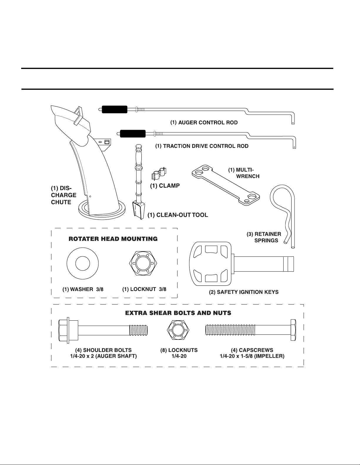
PARTS PACKED SEPARATELY IN CARTON
4
ASSEMBLY / PRE-OPERATION
Read these instructions and this man u al in its entirety before you attempt to assemble or operate your new snow thrower.
Your new snow thrower has been as sem bled at the factory with the ex cep tion of those parts left unassembled for shipping
purposes. All parts such as nuts, washers, bolts, etc., necessary to com plete the as sem bly have been placed in the parts
bag. To ensure safe and proper operation of your snow thrower, all parts and hard ware you assemble must be tightened
se cure ly. Use the correct tools as nec es sary to ensure proper tightness.
REMOVE SNOW THROWER FROM CAR TON
1. Remove all accessible loose parts and parts boxes
from carton.
2. Cut down all four corners of carton and lay panels
fl at.
3. Remove all packing materials ex cept plastic tie holding
speed control rod to lower handle.
4. Remove snow thrower from carton and check carton
thor ough ly for ad di tion al loose parts.
HOW TO SET UP YOUR SNOW THROWER
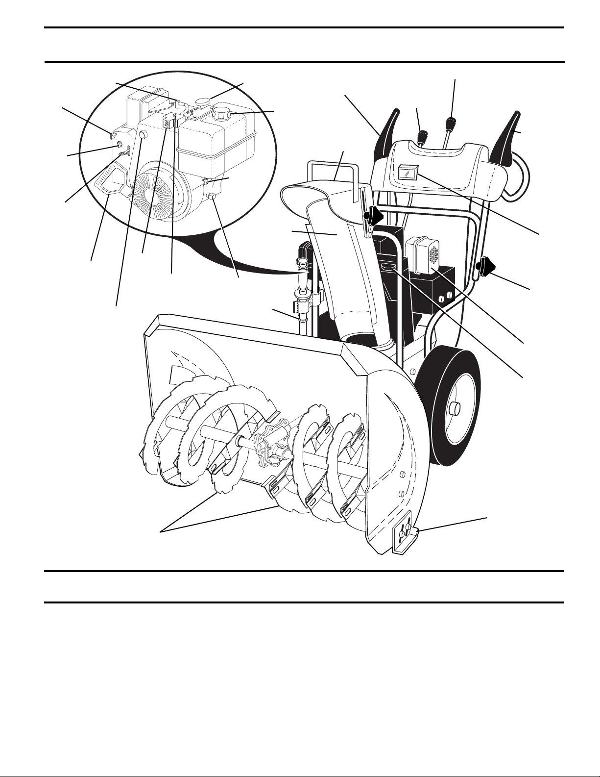
TOOL BOX (See Fig. 8)
A toolbox is provided on your snow thrower. The toolbox
is located on top of the belt cover. Store the extra shear
bolts, nuts and multi-wrench provided in parts bag in the
toolbox.
NOTE: The multi-wrench may be used for assembly of the
chute rotator head to snow thrower and making ad just ments
to the skid plates.
UNFOLD UPPER HANDLE
1. Raise upper handle to the operating position and tight en
handle knobs securely.
SPEED
CONTROL
ROD
PLASTIC TIE
UPPER
HANDLE
HANDLE
KNOB
LOWER
HANDLE
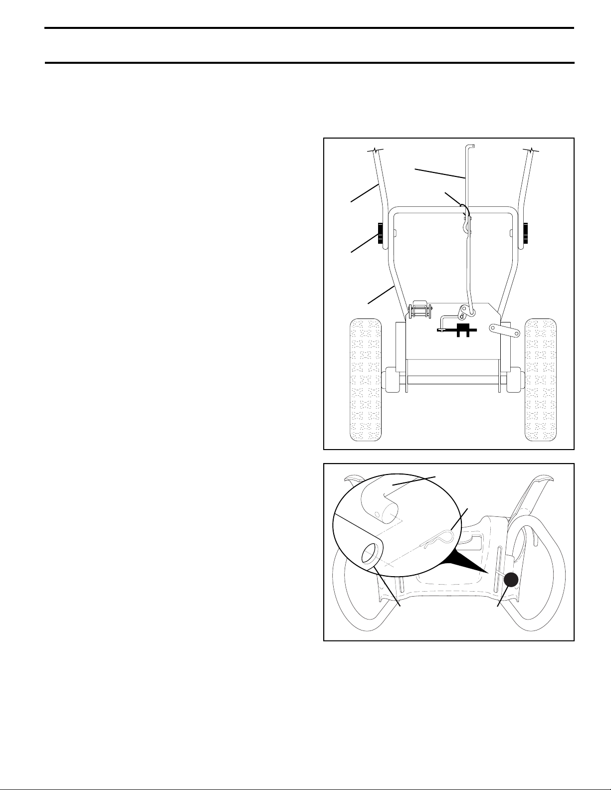
INSTALL SPEED CONTROL ROD (See Figs. 1 and 2)
1. Remove plastic tie securing rod to lower handle.
2. Insert rod into speed control bracket and secure with
retainer spring.
SPEED
CONTROL
BRACKET
FIG. 1
SPEED CON TROL ROD
RETAINER
SPRING
SPEED
CONTROL
LEVER
FIG. 2
5
ASSEMBLY / PRE-OPERATION
INSTALL TRACTION DRIVE CONTROL ROD
(See Figs. 3 and 4)
The traction drive control rod has the long loop on the end
of the spring as shown.
1. Slide rubber sleeve up rod and hook end of spring into
pivot bracket with loop opening down as shown.
2. With top end of rod positioned under left side of control
panel, push rod down and insert top end of rod into hole
in drive control bracket. Secure with retainer spring.
TRACTION DRIVE
CONTROL ROD
RUBBER
SLEEVE
INSTALL AUGER CONTROL ROD (See Figs. 5 and 6)
The auger control rod has the short loop on the end of the
spring as shown.
1. Slide rubber sleeve up rod and hook end of spring into
control arm with loop opening up as shown.
2. With top end of rod positioned under right side of control
panel, push down on rod and insert end of rod into hole
in auger control bracket. Secure with retainer spring.
AUGER
CONTROL
ROD
RUBBER
SLEEVE
CONTROL
ARM
PIVOT
BRACKET
FIG. 3
TRACTION DRIVE
CON TROL LEVER
DRIVE
CONTROL
BRACKET
LOOP
OPEN ING
DOWN
RETAINER
SPRING
TRACTION
DRIVE
CON TROL
ROD
AUGER
CONTROL
ROD
LOOP
OPENING
FIG. 5
RETAINER
SPRING
UP
AUGER
CONTROL
LEVER
AUGER
CONTROL
BRACKET
FIG. 4
FIG. 6
6
ASSEMBLY / PRE-OPERATION
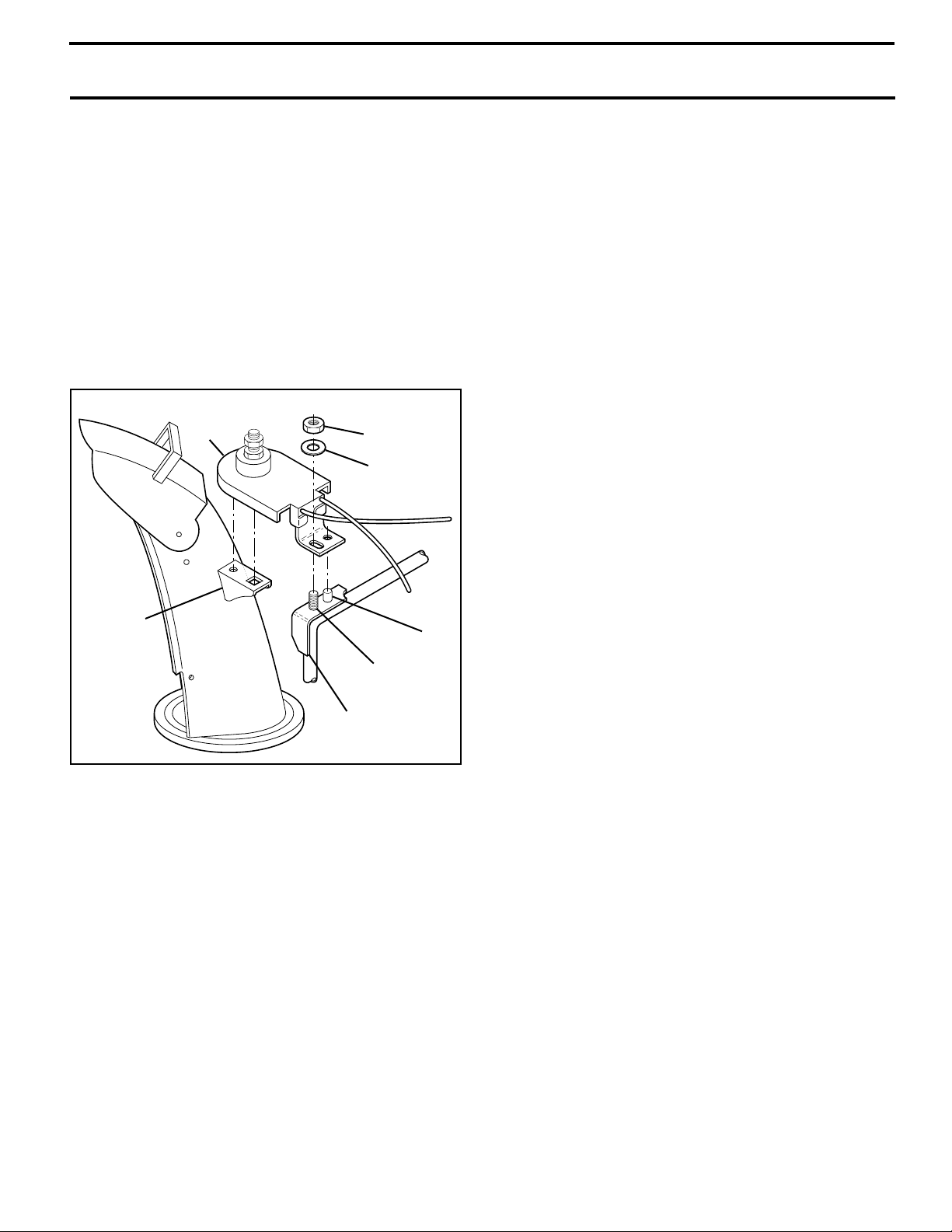
INSTALL DISCHARGE CHUTE / CHUTE ROTATER HEAD
(See Fig. 7)
NOTE: The multi-wrench provided in your parts bag may
be used to install the chute rotater head.
1. Place discharge chute assembly on top of chute base
with discharge opening toward front of snow thrower.
2. Position chute rotater head over chute bracket. If nec es sary, rotate chute assembly to align square and pin
on un der side of chute rotater head with holes in chute
brack et.
3. With chute rotater head and chute bracket aligned,
po si tion chute rotater head on pin and threaded stud
of mounting bracket.
4. Install 3/8 washer and locknut on threaded stud and
tighten securely.
CHUTE
ROTATER
HEAD
3/8 LOCKNUT
3/8 WASHER
CHECK TIRE PRESSURE
The tires on your snow thrower were overinfl ated at the factory for shipping purposes. Correct and equal tire pres sure
is important for best snow throwing performance.
• Reduce tire pressure to 14-17 PSI.
CHUTE
BRACKET
PIN
THREADED
STUD
ROTATER HEAD
MOUNT ING
BRACKET
FIG. 7
7
OPERATION
KNOW YOUR SNOW THROWER
READ THIS OWNER'S MANUAL AND ALL SAFETY RULES BEFORE OPERATING YOUR SNOW THROWER. Compare
the illustrations with your snow thrower to familiarize yourself with the location of various controls and adjustments. Save
this manual for future reference.
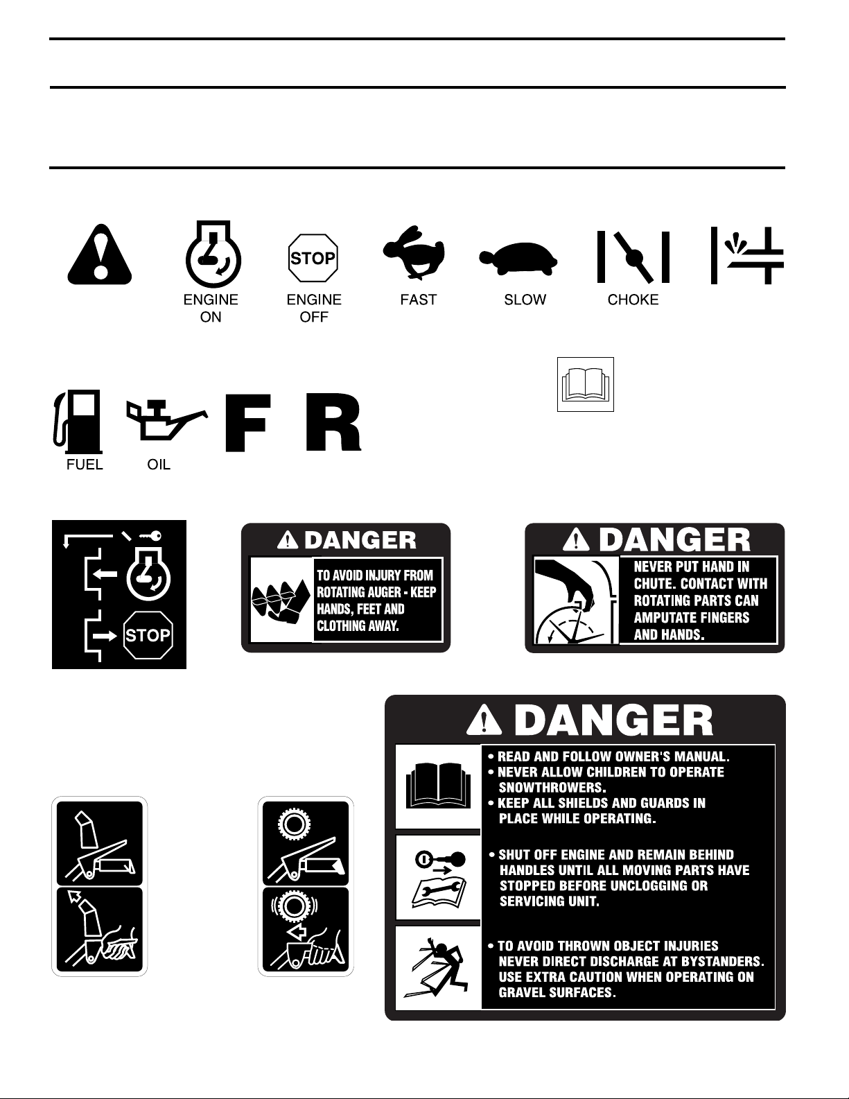
These symbols may appear on your snow thrower or in literature supplied with the product. Learn and understand
their meaning.
DANGER
OR WARNING
IGNITION KEY.
INSERT TO START
AND RUN,
PULL OUT TO STOP.
FORWARD
REVERSE
PRIMER
READ AND FOLLOW ALL SAFETY INFORMATION
AND INSTRUCTIONS BEFORE USE OF THIS PRODUCT.
KEEP THESE INSTRUCTIONS FOR FUTURE REFERENCE.
SNOW
DISCHARGE
DISENGAGED
ENGAGED
TRACTION
DRIVE CONTROL
8
OPERATION
SPARK
SAFETY
IGNITION
KEY
CHOKE
CON TROL
THROTTLE
/ ENGINE
CONTROL
NOTE: ITEMS ABOVE
LOCATION ON THE
ENGINE. ACTUAL
LOCATION MAY VARY
WITH THE ENGINE
PLUG
RECOIL
STARTER
HANDLE
PRIM ER
ARE SHOWN IN
THEIR TYPICAL
ON YOUR UNIT.
POWER
CORD
PLUG
ELECTRIC
START
BUTTON
ENGINE OIL CAP
WITH DIPSTICK
FUEL
SHUT-OFF
VALV E
DISCHARGE
CHUTE
OIL DRAIN PLUG
CLEAN-OUT TOOL
GAS O LINE
FILLER
CAP
AUGER
CONTROL
LEVER
CHUTE
DE FLEC TOR
DISCHARGE CHUTE CONTROL LEVER
DRIVE SPEED
CON TROL LEVER
TRACTION
DRIVE
CONTROL
LEVER
LIGHT
HANDLE
KNOB
MUF FLER
TOOL BOX
AU GERS
FIG. 8
MEETS A.N.S.I. SAFETY REQUIREMENTS
Our snow throwers conform to the standards of the American National Standards Institute.
Toolbox - used to store spare shear bolts, locknuts and
wrench.
Safety ignition key - must be inserted for the engine to
start and run. Remove when snow thrower is not in use.
Electric start button - used for starting the engine.
Recoil (auxiliary) starter handle - used for start ing the
en gine.
Primer - pumps additional fuel from the carburetor to the
cylinder for use when starting a cold engine.
Throttle/engine control - used to se lect either FAST or
SLOW engine speed and to STOP the engine.
Choke control - used for starting a cold engine.
Drive speed control lever - used to select forward or
reverse motion and speed of snow thrower.
Traction drive control lever - used to engage power-pro pelled for ward or reverse motion of snow thrower.
Auger control lever - used to engage auger motion (throw
snow).
Discharge chute control lever - used to change the di rec tion the snow is thrown.
Skid plate - used to adjust height of scraper bar from the
ground.
9
SKID PLATE
OPERATION
The operation of any snow thrower can result
in foreign objects thrown into the eyes, which
can result in severe eye damage. Always wear
safety glasses or eye shields while operating
your snow thrower or performing any ad just ments or repairs. We recommend standard safe ty glasses
or a wide vision safety mask worn over spectacles.
HOW TO USE YOUR SNOW THROWER
Know how to operate all controls before adding fuel or
attempting to start the engine.
STOPPING
TRACTION DRIVE
• Release traction drive control lever to stop the forward
or reverse movement of the snow thrower.
AUGER
• Release the auger control lever to stop throwing snow.
ENGINE
1. Move throttle control to “STOP” position.
2. Remove (do not turn) safety ignition key to prevent
unauthorized use.
NOTE: Never use choke to stop engine.
TO USE FUEL SHUT-OFF VALVE (See Fig. 9)
The fuel shut-off valve is located beneath the fuel tank on
the engine. Always op er ate the snow thrower with the fuel
shut-off valve in the OPEN position.
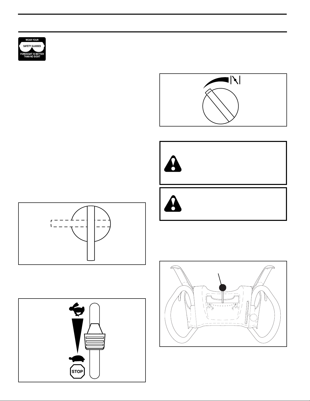
TO USE CHOKE CON TROL (See Fig. 11)
The choke con trol is located on the en gine. Use the choke
control when ev er you are starting a cold en gine. Do not
use to start a warm en gine.
• To engage choke, turn knob clockwise. Slowly turn
knob counterclockwise to disengage.
FULLOFF
FIG. 11
TO CONTROL SNOW DISCHARGE (See Figs. 12 & 13)
WARNING: Snow throwers have ex posed rotating parts, which can cause
severe injury from contact, or from material thrown from the discharge chute.
Keep the area of operation clear of all
persons, small children and pets at all
times including startup.
WARNING: If the discharge chute or au ger become clogged, shut-off en gine
and wait for all moving parts to stop. Use
the clean-out tool, NOT YOUR HANDS,
to un clog the chute and/or auger.
OFF
OPEN
FIG. 9
TO USE THROTTLE CONTROL (See Fig. 10)
The throttle control is located on the engine. Always op er ate
the snow thrower with the engine at full throttle. Full throttle
offers the best snow thrower performance.
FAS T
SLOW
FIG. 10
The DIRECTION in which snow is to be thrown is controlled
by the discharge chute control lever.
• To change the discharge chute position, press down ward on discharge chute control lever and move lever
left or right until chute is in desired position. Be sure
lever springs back and locks into desired position.
DISCHARGE CHUTE
CONTROL LEVER
FIG. 12
The DISTANCE that snow is thrown is controlled by the
position of the chute defl ector. Set the defl ector low to
throw snow a short distance; set the defl ector higher to
throw snow farther.
• To change the defl ector position, loosen knob, move de-
10
fl ector to desired position and tighten knob securely.
 Loading...