

Page 1

Shindaiwa
Trimmer Head
Guide
How to load and service the
most popular Shindaiwa trimmer heads, including complete
replacement parts information
and other important technical
data.
First To Start. Last To Quit.
Item 80792 6/03
Page 2

Shindaiwa Trimmer Head Guide
INTRODUCTION
Shindaiwa offers several types of
trimmer heads to meet the requirements of our customers. This booklet
will help you – the distributor and
dealer – to help your customers
decide which trimmer heads to
purchase, as well as give them stepby-step instructions on how to untangle the mess of installing trimmer
line.
Each Shindaiwa trimmer head
comes with a set of instructions on
line installation. In the event that
these instructions are lost or misplaced, feel free to provide your
customers with a copy of the instructions from this booklet that matches
their particular trimmer head.
CONTENTS
page no.
General Trimmer Head
Information.................................... 3
Low Profile Manual Head.................. 4
SemiMatic Trimmer Head ................. 6
E-Z Load and E-Z Pro
Trimmer Heads............................. 8
High Capacity Trimmer Head ......... 10
Midget Manual and High Profile
Trimmer Heads........................... 12
Pro-Matic and Bump ’N’ Cut
Trimmer Heads........................... 14
HomePro Semi-Auto Feed.............. 16
Pro Semi-Matic ............................... 18
ADAPTER BOLTS BY MODEL
Current Models Bolt Size
22F 8mm / MRH
F230 8mm / MRH
22T 7mm / MLH
T230, T231, C230,
T2500, 65001 7mm / MLH
T250, C250 8mm / MLH
T260, T261, C260 8mm / MLH
T270, T271, C270,
T350 8mm / MLH
C350, B450, B530 10mm / MLH
Discontinued Models Bolt Size
BP35 8mm / MLH
B40 10mm / MLH
B45 10mm / MLH
C35 10mm / MLH
F18 8mm / MRH
F20 8mm / MLH
F21 8mm / MRH
LT18 7mm / MLH
LT20 7mm / MLH
T18 7mm / MLH
T20, C20 7mm / MLH
T25, C25 8mm / MLH
T27, C27 8mm / MLH
MLH Male, Left Hand Thread
MRH Male, Right Hand Thread
FLH Female, Left Hand Thread
FRH Female, Right Hand Thread
UN-10.............................................. 20
UN-30.............................................. 21
UN-32.............................................. 22
Flail Trimmer Head ......................... 23
Super Flail Trimmer Head............... 24
Fixed Line Trimmer Head ............... 25
Heavy-Duty Fixed Line Head.......... 26
Adaptors.......................................... 27
2
Page 3

General Trimmer Head Maintenance Information
The most common cause of trimmer
head malfunction is poor maintenance, especially true for tap-for-line,
bump-feed, and fully automatic heads.
Customers buy these heads for
convenience so they don’t have to
reach down and advance the line–yet
that added convenience often means
the head is not properly maintained.
A Few Tips
■ Clean the head thoroughly each time
line is refilled. Wipe all grass and
debris from internal parts. Water will
dissolve accumulated buildup, but a
cleaner such as 409™ will aid in the
task.
■ Replace worn eyelets. Never run a
trimmer head without eyelets installed. Running with an eyelet
missing will cause the trimmer line to
wear into the body of the head as
well as create excessive vibration.
■ Replace any noticeably worn parts. A
knob at the bottom of a head is a
wear part if it contacts the ground,
especially in abrasive soil conditions
and when the head is run against
sidewalks and curbs.
■ When winding line, keep both strings
separate. Try to wind as evenly as
possible to prevent snarling and
reduce vibration.
■ Trim line ends to equal length from
the eyelet. Operation with uneven
length trimmer line will cause
excessive vibration.
■ Always replace worn or damaged
parts promptly .
■ Make sure line is wound in the
correct direction for the rotation of
the head–
For heads with a LH arbor bolt,
wind line counterclockwise as viewed
from the knob at the end of the
trimmer head.
For heads with a RH arbor bolt,
wind line clockwise as viewed from
the knob.
“Clockwise for RH,
Counterclockwise for LH”
Any plastic material can dry out,
especially when stored at high temperature and when exposed to direct
sunlight. To prevent this, Shindaiwa
packages much of their trimmer line in
all-plastic holders so the line can be
soaked in water to restore moisture.
Trimmer line with very low moisture
content is brittle and inflexible. Winding dry line on a trimmer head can be
very difficult. After soaking in water,
the same line will become very flexible
and far tougher, and service life will
be significantly extended. NOTE: This
also applies to flail blades.
CAUTION: Remove the bearing or
bushing from from Super Flail blades
before soaking in water.
The Shindaiwa Warranty
Shindaiwa warrants trimmer heads to
be free of defects in materials and
workmanship for 90 days. The warranty is for replacement parts only –
not the entire trimmer head. Damage
caused by wear, running with missing
parts, etc. is not covered.
Q
uestion:
carry so many trimmer heads?
A
nswer:
for different applications. Some heads
feature manual adjustment of line
length while others are tap-for-line
models. In addition, some trimmer
heads are intended for consumer use
and others are intended primarily for
commercial applications.
Why does Shindaiwa
There are different heads
CONSUMER HEADS
Manual
Midget Head
manual head for small-displace-
ment trimmers.
Tap-for-Line
Bump & Cut
for-line head for small-displace-
ment trimmers.
3-Blade Flail
Economical flail head for weeds,
light brush and grass.
An inexpensive
An inexpensive tap-
COMMERCIAL HEADS
Manual
Low Profile
medium-duty manual head.
High Profile
manual head. Best choice for
abrasive soil conditions where
head is in contact with the ground.
Tap-for-Line
Pro-Matic
for-line head.
EZ-Load
reassemble.
EZ-Pro
larger line capacity.
SemiMatic
head. Stays clean by design. Reel
in cover for fast reloading.
Pro-Head
head.
Fixed-Line Head
One-piece die cast metal head. No
moving parts to lose. First choice
for many commercial users.
Contains grooves in sides to
prevent line shearing when head
contacts solid objects. Permits
cutting lower to the ground than
any other line cutting attachment.
Super Flail Head
Heavy-duty head for thick, tough
grass and brush.
NOTE: Flail-type heads are not a
good choice for stemmy material
such as mature blackberry vines
and tree seedlings.
Reasonably priced
Proven “old reliable”
General purpose tap-
Simple to load, easy to
Similar to EZ-Load with
Tough tap-for-line
Professional tap-for-line
3
Page 4
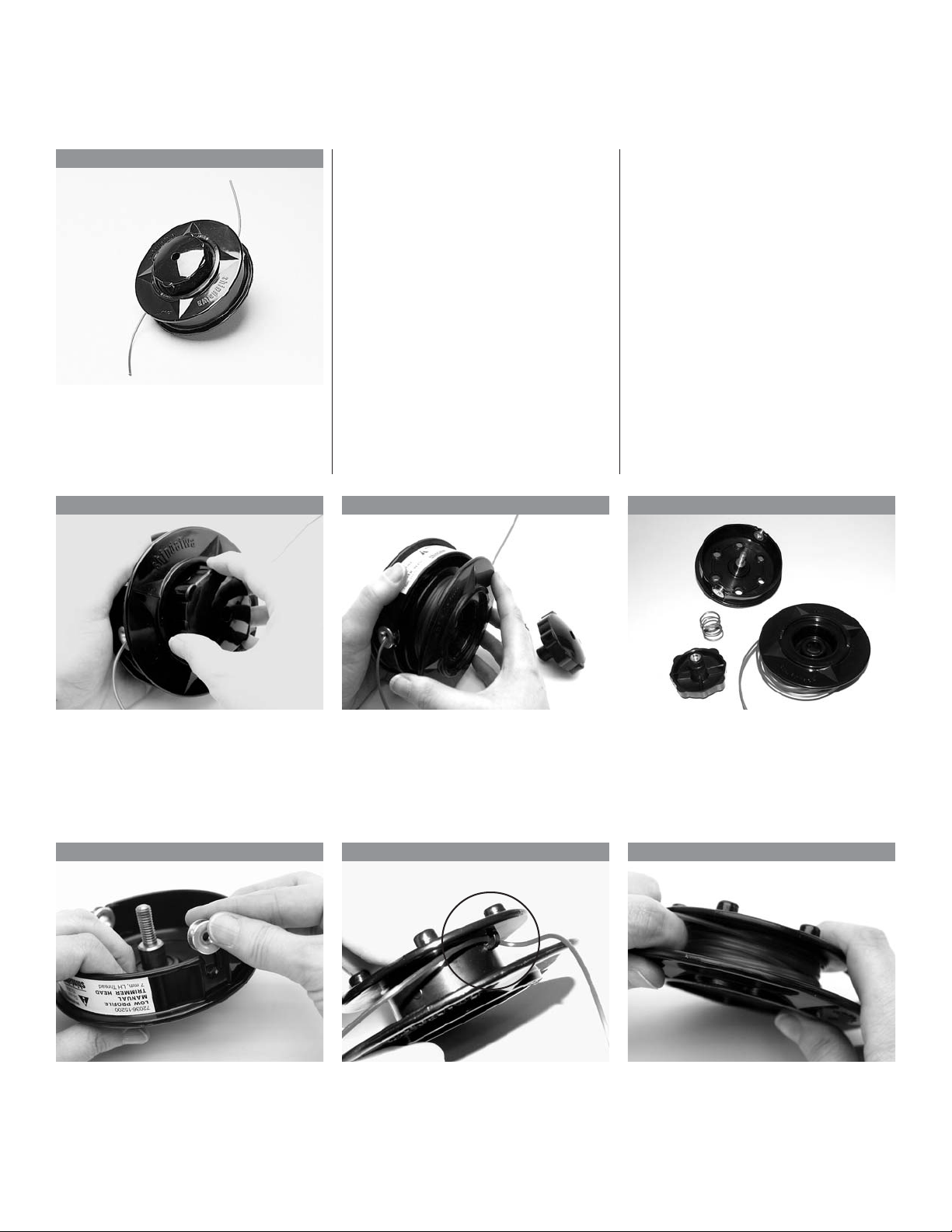
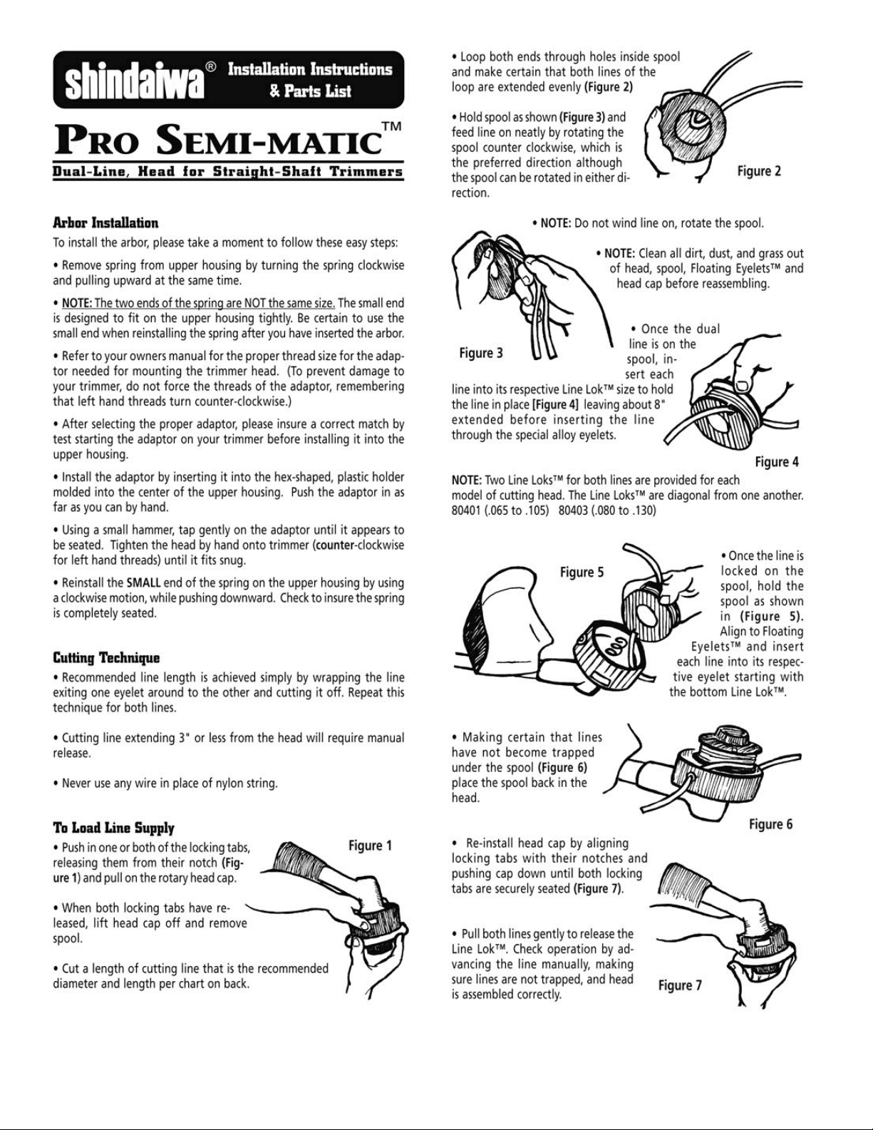
INSTALLATION INSTRUCTIONS
Low Profile Manual Trimmer Head
Model View
72036-15200
Fits LT18, T18, T20, C20, LT20, T230,
C230, 22T
72005-92001
Fits F20, T25, C25, T27, C27, BP35,
T250, C250, T270, C270, T260, C260,
T350
72017-92001
Fits C35, C350, RC45, B45, B450
NOTE: Operating with trimmer line of
uneven length will cause excessive
vibration. Always make sure the line is
wound evenly and trimmed to equal
lengths from the eyelets.
Line Chart
72036-15200
72005-92001
72017-92001
Shipped with
20 feet of .080 line.
Maximum fill–
40 feet of .080
30 feet of .095
26 feet of .105
1 2 3
Remove the knob and spring (turn
counterclockwise to remove).
Remove the line spool. Clean the spool, housing and eyelets.
4 5 6
Reattach the eyelets if they were
removed. Never operate a trimmer
head head without eyelets!
Replace the line by threading it
through the eyelet in the spool until
the line ends are of about equal
length. Refer to the Line Chart
(above) for the proper amount of line.
Inspect for wear and damage.
Replace damaged components.
Bend the line at the eyelet to form two
lengths. Wind both ends clockwise as
viewed from the underside of the
head.
4
Page 5
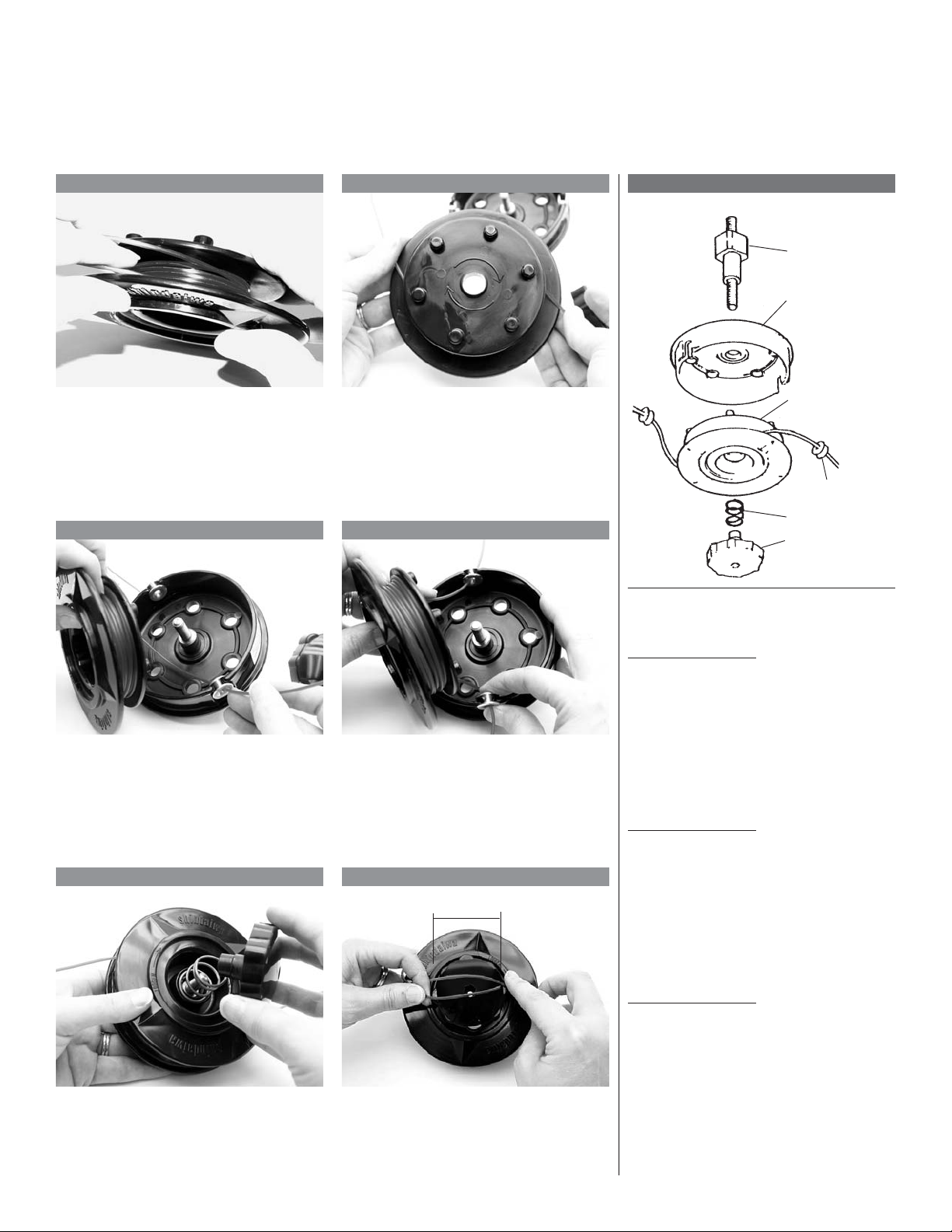
To advance line: With the engine off, loosen the bottom knob a few turns in
the direction of rotation. Grasp the trimmer head in both hands. Rotate the
bottom of the spool clockwise and pull the line through the eyelets. Re-tighten
the knob before operating the trimmer.
7 8
Use your finger to separate the line
into two sections. Doing so will assist
in a smooth line feed when the head
is reassembled.
9 10
Hold the spool over the housing and
feed one line end into an eyelet. As
you place the spool in the head, feed
the other line into the opposite eyelet.
Make sure one line does not slide
under the spool.
11 12
Holding the spool and wound line
in one hand, place the lines 180
degrees apart.
Tip: Sometimes it’s easier to remove
one eyelet to install the second piece
of line. Slide the eyelet over the line
two to three inches, then push the
eyelet in place as the spool is replaced in the housing.
1" to 2"
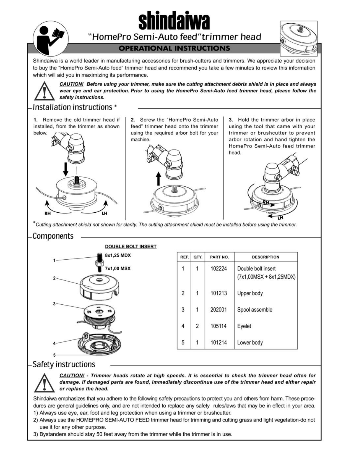
PARTS LIST
1 Adapter Bolt
2 Outer Housing
3 Inner Spool
4 Eyelets
5 Spring
6 Button/Knob
Low Profile Head
72036-15200
Item Part No.
1 72036-15210
2 72005-92740
3* 72005-92630
4 72005-92720
5 72005-92660
6 72005-92770
72005-92001
Item Part No.
1 72005-92710
2 72005-92740
3* 72005-92630
4 72005-92720
5 72005-92660
6 72005-92770
Reinstall the spring and knob. Tighten
securely.
A properly wound and reassembled
head should have four or five inches
of line extending from each eyelet and
the overlap should be one to two
inches. Trim as needed to final length.
72017-92001
Item Part No.
1 72017-92710
2 72005-92740
3* 72005-92630
4 72005-92720
5 72005-92660
6 72005-92770
*2 required
5
Page 6
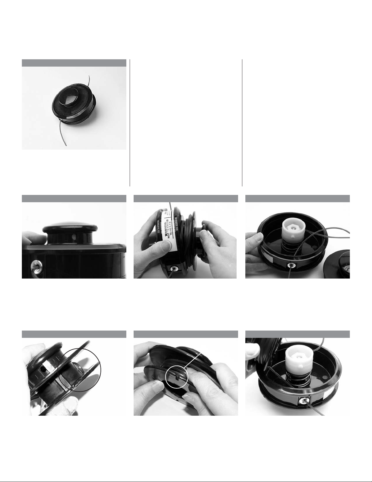
INSTALLATION INSTRUCTIONS
SemiMatic Trimmer Head
Model View
99909-15500
Fits LT18, T18, T20, C20, LT20, T230,
C230, 22T
99909-15600
Fits F20, T25, C25, T27, C27, BP35,
T250, C250, T260, C260
NOTE: Operating with trimmer line of
uneven length will cause excessive
vibration. Always make sure the line is
wound evenly and trimmed to equal
lengths from the eyelets.
Line Chart
99909-15500
99909-15600
Shipped with 10 feet of .095 line
Maximum fill–
1 2 3
40 feet of .080
26 feet of .095
20 feet of .105
Turn the knob clockwise to remove
the knob and spool (one piece). Make
sure the white lock tab is visible in the
“L” window on the knob before starting
to turn.
Remove the knob and spool. Clean the housing and spool and
4 5 6
Spool Saver
Slot
Replace the line by threading it
through the eyelet in the spool until
the line ends are of equal length.
With the knob facing away from you,
wind the line counterclockwise. Hook
the line into line saver slots in the
spool housing.
inspect for damage and wear. If the
eyelets are worn excessively, replace
the housing. Note: The inner and
outer cams in the spool can be
serviced by a dealer.
Install the knob and spool in the
housing while threading the line
through the eyelets. Pull the line to
seat the spool.
6
Page 7
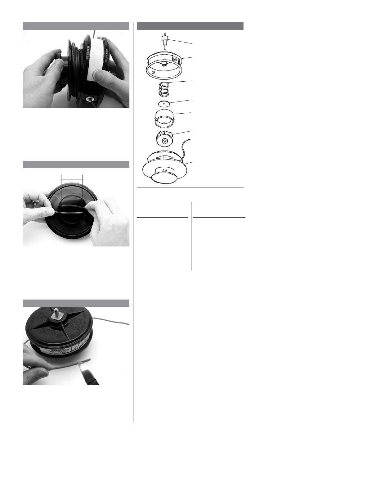
7
PARTS LIST
1 Adapter Bolt
2 Outer Housing
3 Spring
4 Washer
Turn the knob/spool counterclockwise
to lock the spool in the housing. You
will feel a firm “click” when the white
lock tab snaps into place.
8
1" to 2"
A properly reassembled head should
have four to five inches of line extending from each eyelet, and the total
overlap should be one to two inches.
SemiMatic
99909-15500
Item Part No.
1 72036-15210
2 99909-15510
3 99909-15520
4 99909-15530
5 99909-15540
6 99909-15550
7 99909-15560
5 Cam Assembly
6 Cam Lock
7 Inner Spool
99909-15600
Item Part No.
1 72005-92710
2 99909-15510
3 99909-15520
4 99909-15530
5 99909-15540
6 99909-15550
7 99909-15560
9
Trim the line to equal length as
required to avoid excessive vibration.
7
Page 8
INSTALLATION INSTRUCTIONS
E-Z Load and E-Z Pro Trimmer Heads
E-Z Load E-Z Pro
E-Z Load
99909-017
Fits LT18, T18, LT20, T20, C20, T230,
C230, 22T
99909-018
Fits F20, T25, C25, T250, C250, T27,
C27, T270, C270, T260, C260, BP35
99909-018RB
Fits 22F
E-Z Pro
99909-028
Fits T25, C25, T27, C27, T250, C250,
T270, C270
99909-020
Fits B40, B45, B450, C35, C350,
RC45
1 2 3
NOTE: Operating with trimmer line of
uneven length will cause excessive
vibration. Always make sure the line is
wound evenly and trimmed to equal
lengths from the eyelets.
Line Chart
E-Z Load
99909-017
99909-018
Shipped with 15
feet of .095 line.
Maximum fill–
45 feet of .080
34 feet of .095
32 feet of .105
E-Z Pro
99909-028
99909-020
Shipped with 15 feet
of .095 line.
Maximum fill–
50 feet of .080
40 feet of .095
36 feet of .105
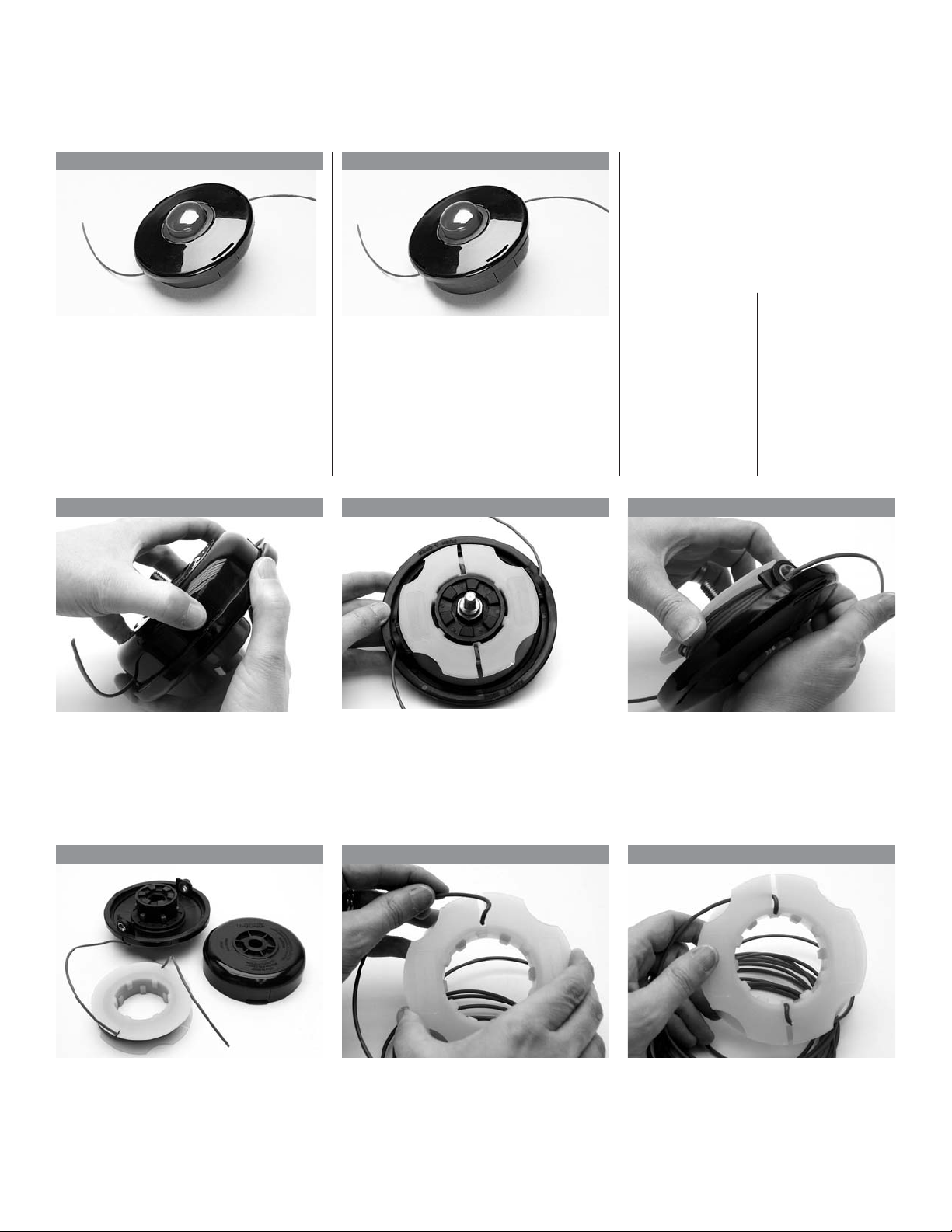
Press the upper body in at the spots
marked “Push Open”. Pull the lower
part of the trimmer head down.
Remove the line spool from the lower
body of the trimmer.
4 5 6
Clean and inspect the spool, housing
and eyelets. Replace worn or damaged components.
Cut two equal lengths of trimmer line,
no longer than 25 feet each. Place an
end from each piece of line in the
holes in the center of the spool.
If nylon line is extending through the
eyelets, push the bump knob in while
rotating the line spool until the slots in
the spool line up with the eyelets, then
remove the spool.
While holding the line ends, pull each
line down toward the inside of the
spool through the slots next to the
holes.
8
Page 9
7 8
PARTS LIST
1 Outer Housing
2 Adapter Bolt
3 Inner Spool
4 Outer Cover
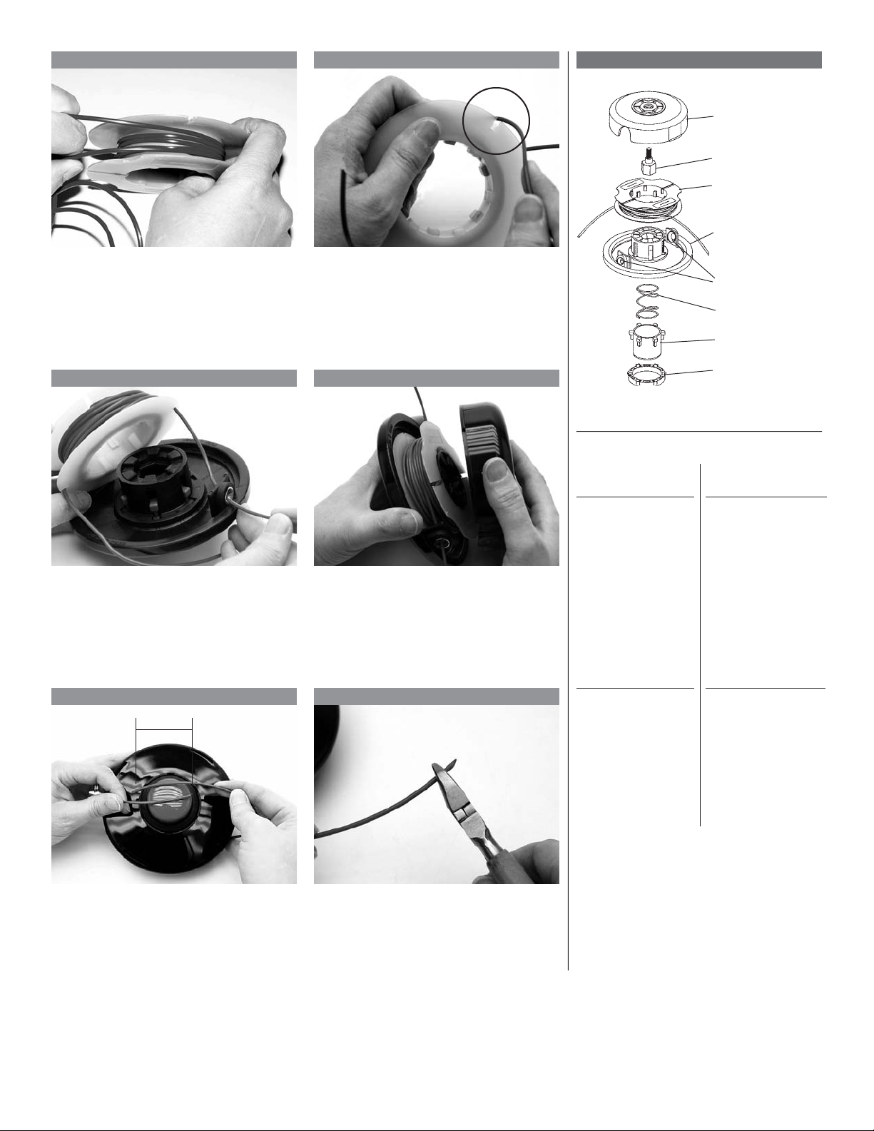
With line saver slots facing away from
you, wind the line clockwise on the
spool. Use a finger to keep the two
lines separate (spool shown is for
99909-017).
9 10
Thread the ends of the line into the
eyelets in the housing. Do not allow
line to go under spool.
11 12
1" to 2"
Lock the ends of the line in the line
saver slots in the spool.
Replace the cover by aligning the
tabs, then snap the cover in place.
Pull line free from the line saver slots.
E-Z Load
99909-017
Item Part No.
1 101134
2 102351
3 101030
4 101135
5* 105115
6 107001
7 101136
8 101137
99909-028
Item Part No.
1 101170
2 102349
3 101171
4 101172
5* 106007
6 107001
7 101136
8 101137
5 Eyelets
6 Spring
7 Button/Knob
8 Retaining Ring
E-Z Pro
99909-018
Item Part No.
1 101134
2 102350
3 101030
4 101135
5* 105115
6 107001
7 101136
8 101137
99909-020
Item Part No.
1 101170
2 102350
3 101171
4 101172
5* 106007
6 107001
7 101136
8 101137
Check for a maximum line overlap of
one to two inches (four to five inches
of line extending from each eyelet).
*2 required
Trim as required to final length.
9
Page 10

INSTALLATION INSTRUCTIONS
High Capacity Trimmer Head
Model View
Note: This trimmer head can operate
either as a manual feed or a bump
feed.
99909-007
Fits T230 and C230
99909-008
Fits T27, C27, T270, C270, T260,
C260, BP35
NOTE: Operating with trimmer line of
uneven length will cause excessive
vibration. Always make sure the line is
wound evenly and trimmed to equal
lengths from the eyelets.
Line Chart
99909-007
99909-008
Shipped with 21 feet of .080 line.
Maximum fill–
1 2 3
50 feet of .080
40 feet of .095
36 feet of .105
Turn the lower knob at the bottom of
the trimmer head clockwise to disassemble the halves.
Remove the spool from the housing.
4 5 6
Inspect the arbor bolt and replace it if
damaged. Reattach the eyelets if they
were removed or replaced. Never
operate a trimmer head without
eyelets!
Cut two equal lengths of trimmer line,
no longer than 25 feet each. Place an
end from each piece of line into the
holes in the center of the spool.
Clean the spool, housing and eyelets.
Inspect for wear and damage.
Replace damaged components.
Wind the line clockwise onto the spool
following the direction of the arrows
stamped into the spool.
10
Page 11

7 8
Line Saver
Slot
Continue winding the line onto the
spool, keeping one finger between
the lines. Lock the ends of each line
segment into line saver slots in the
spool.
Thread the ends of the line into the
eyelets in the housing. Do not allow
line to go under the spool.
PARTS LIST
1 Adapter Bolt
2 Outer Housing
3 Eyelets
4 Inner Spool
5 Retaining Ring
6 Outer Cover
7 Spring
8 Spring Housing
9 Button/Knob
9 10
Replace the arbor bolt in the top of
the trimmer head. Install the spacers
as shown.
11 12
1" to 2"
Replace the cover. Tighten the lower
knob by turning counterclockwise.
Pull the line ends free from the line
saver slots.
High Capacity
99909-007
Item Part No.
1 99909-217
2 101061
3* 106003
4 101030
5 103025
6 101053
7 107006
8 101054
9 101074
10 102082
11 101072
*2 required
10 Retainer Bolt
11 Knob Tap
99909-008
Item Part No.
199909-218
2 101061
3* 106003
4 101030
5 103025
6 101053
7 107006
8 101054
9 101074
10 102082
11 101072
Check for maximum line overlap of
one to two inches (four to five inches
of line extending from each eyelet).
Trim as required to final length.
11
Page 12

INSTALLATION INSTRUCTIONS
Midget Manual and High Profile Trimmer Heads
Midget Manual High Profile
72414-15100*
Fits F18, F21, F230
72086-15100
Fits LT18, T18, T20, C20, LT20,
T230, C230, 22T
72031-15100
F20
72005-92600
Fits T25, C25, T27, C27, BP35, T250,
C250, T260, C260, T270, C270, T350
99909-151
Fits C35, B45, RC45, C350, B450
1 2 3
NOTE: Operating with trimmer line of
uneven length will cause excessive
vibration. Always make sure the line is
wound evenly and trimmed to equal
lengths from the eyelets.
Line Chart
Midget Manual
72414-15100
72086-15100
72031-15100
Shipped with 14
feet of .080 line.
Maximum fill–
26 feet of .080
6 feet of .095
High Profile
72005-92600
99909-151
Shipped with 21 feet
of .095 line.
Maximum fill–
26 feet of .095
20 feet of .105
Remove the wing nut knob and spring
(turn counterclockwise to remove on
72414-15100; turn clockwise on all
others).
Remove the line spool. Clean the spool, housing and eyelets.
4 5 6
Reattach the eyelets (if they were
removed). Never run a trimmer head
without eyelets!
Replace the line by threading through
the eyelet in the spool until the line
ends are of equal length. Refer to the
Line Chart (above) for the proper
amount of line.
Inspect for wear and damage, and
replace damaged components.
Bend the line at spool eyelet to form
two lengths. 72414-15100: Wind both
ends clockwise as viewed from the
underside of the head. All others:
Wind counterclockwise.
12
Page 13

To advance line: With the engine off, loosen the wing nut a few turns in the
direction of rotation. Grasp the trimmer head with both hands. Rotate the
bottom of the spool clockwise and pull the line through the eyelets. Re-tighten
the wing nut before operating the trimmer.
7 8
Use your finger to separate the line
end into two separate sections. Doing
so will assist in a smooth line feed
when the head is reassembled.
9 10
Hold the spool over the housing and
feed one line into an eyelet. As you
place the spool in the head, feed the
other line into the opposite eyelet.
Make sure one line does not slide
under the spool.
11 12
Holding the spool and wound line in
one hand, place the line ends 180
degrees apart. Note: The photo
illustrates the spool for 72414-15100.
Tip: Sometimes it’s easier to remove
one eyelet when installing the second
piece of line. Slide the eyelet over the
line for two to three inches, then push
the eyelet in place as the spool is
replaced in the housing.
1" to 2"
PARTS LIST
Midget Manual
Midget Manual
Head
72414-15100
Item Part No.
1 72414-15110
2 72414-15120
3* 72005-92630
4 72414-15140
5 72005-92660
6 72414-15160
72086-15100
Item Part No.
1 72086-15110
2 72414-15120
3* 72005-92630
4 72414-15140
5 72005-92660
6 72031-15160
High Profile
1
Adapter
Bolt
2
Outer
Housing
3
Eyelets
4
Inner
Spool
5
Spring
6
Knob
High Profile
Head
72005-92600
Item Part No.
1 72005-92710
2 72005-92620
3* 72005-92630
4 72005-92640
5 72005-92660
6 72031-15160
99909-151
Item Part No.
1 72017-92710
2 72005-92620
3* 72005-92630
4 72005-92640
5 72005-92660
6 72031-15160
Reinstall the spring and wing nut
knob. Tighten firmly.
A properly reassembled head should
have four to five inches of line extending from each eyelet, and the overlap
should be one to two inches. Trim as
required to final length.
72031-15100
Item Part No.
1 72005-92710
2 72414-15120
3* 72005-92630
4 72414-15140
5 72005-92660
6 72031-15160
*2 required
13
Page 14

INSTALLATION INSTRUCTIONS
Pro-Matic and Bump ‘N’ Cut Trimmer Heads
Pro-Matic Bump ‘N’ Cut
UN32-7L
Fits LT18, T18, T20, C20, LT20, T230,
C230, 22T
UN32-8L
Fits F20, T25, C25, T27, C27, BP35,
TC250, T270, C270, T260, C260
UN32-10L
Fits C35, C350, RC45, B45, B450
UN34-7L
Fits LT18, T18, LT20, T20, C20, T230,
C230, 22T
UN34-8R
Fits F18, F21, F230, 22F
1 2 3
NOTE: Operating with trimmer line of
uneven length will cause excessive
vibration. Always make sure the line is
wound evenly and trimmed to equal
lengths from the eyelets.
Line Chart
UN32-7L
UN32-8L
UN32-10L
Shipped with
18 feet of .080 line.
Maximum fill–
40 feet of .080
28 feet of .095
26 feet of .105
UN34-8R
Shipped with
21 feet of .080 line.
Maximum fill–
33 feet of .080
16 feet of .095
14 feet of .105
Depress the tab on the lower housing
and twist the cover counterclockwise
(clockwise on UN34-8R) to align
arrows. Remove the cover and button.
Remove the spool and spring (the
spring is located under the spool).
4 5 6
Inspect the arbor bolt and replace it if
damaged. Re-attach the eyelets if
they were removed or replaced.
Never operate a trimmer head
without eyelets!
Replace the line by threading it
through the eyelet in the spool until
line lengths are equal. Refer to the
Line Chart (above) for the proper
amount of line.
Clean the spool, housing and eyelets.
Inspect for wear and damage.
Replace damaged components.
With line saver slots facing you,
wind the line clockwise in the spool
using a finger to keep the two lines
separate (UN34-8R: Wind the line
counterclockwise).
14
Page 15

7 8
Lock the ends of line into line saver
slots in spool.
Insert the spring onto the bolt. With
the line saver slots on the spool facing
the bolt, thread the ends of the line
into the eyelets in the housing. Do not
allow the line to go under the spool.
PARTS LIST
2 Eyelet
1 Outer Housing
3 Adapter Bolt
4 Spring
5 Inner Spool
6 Button/Knob
9 10
Place the button in the center of`the
spool.
11 12
1" to 2"
Check for a maximum line overlap of
one to two inches (four to five inches
of line extending from each eyelet).
Replace the cover by aligning the tabs
and then twisting counterclockwise as
viewed from the button side of the
head (UN34-8R: Twist clockwise).
Pull the line free from the line saver
slots.
Trim as required to final length.
Pro-Matic (UN-32)
UN32-7L
Item Part No.
1 99909-15700
2* 72005-92630
3 99909-15720
4 99909-15520
5 99909-15580
6 99909-15590
7 99909-15610
UN32-10L
Item Part No.
1 99909-15700
2* 72005-92630
3 99909-15740
4 99909-15520
Bump ‘N’ Cut (UN-34)
UN34-7L
Item Part No.
1 99909-15710
2* 72005-92630
3 99909-15720
4 72078-15240
5 99909-15770
6 99909-15780
7 99909-15755
UN32-8L
Item Part No.
Item Part No.
UN34-8R
Item Part No.
7 Outer Cover
1 99909-15700
2* 72005-92630
3 99909-15730
4 99909-15520
5 99909-15580
6 99909-15590
7 99909-15610
5 99909-15580
6 99909-15590
7 99909-15610
1 99909-15790
2 72005-92630
3 99909-15800
4 72078-15240
5 99909-15810
6 99909-15780
7 99909-15750
*2 required
15
Page 16
1617181920
Page 17

Page 18
Page 19

Page 20

UN10 Assembly and Rewinding Instructions
WARNING!
䡵 Do not make unauthorized
modifications or alterations to this
unit or its components. Nonstandard parts may not operate
properly with this trimmer head
and may cause damage and lead
to personal injury.
䡵 Always wear eye protection such
as goggles or safety glasses to
shield against thrown objects.
䡵 Reduce the risk of bystanders
being struck by flying debris. Make
sure no one is within 50 feet (15
meters)—that’s about 16 paces—
of an operating attachment.
NOTE:
Each package contains (3) steel studs.
Select the correct stud for your Shindaiwa trimmer or brushcutter model.
A. 7mm LH (gold p/n 80676)
(Fits 22T, 22C, T230, T231, C230,
T2500, T2500X, 65001 multipurpose
tool)
B. 8mm LH (silver p/n 80677)
(Fits T260, T261, C260, T270, T272X,
C270, T350)
C. 10mm LH (silver p/n 80678)
(Fits C350, B450, B530)
Line capacity:
.080” .... 38’
.095” .... 26’
.105” .... 20’
A B C
Arbor Bolt (1)
p/n 80730
Eyelet (2)
p/n 72005-92630
Housing (1)
p/n 72005-92620
Spool (1)
p/n 72005-92640
Spring (1)
p/n 72005-92660
Knob (1)
1
2
p/n 72031-15160
3 4 5
6 7 8
Page 21

UN30 Assembly and Rewinding Instructions
WARNING!
䡵 Do not make unauthorized
modifications or alterations to this
unit or its components. Nonstandard parts may not operate
properly with this trimmer head
and may cause damage and lead
to personal injury.
䡵 Always wear eye protection such
as goggles or safety glasses to
shield against thrown objects.
䡵 Reduce the risk of bystanders
being struck by flying debris. Make
sure no one is within 50 feet (15
meters)—that’s about 16 paces—
of an operating attachment.
NOTE:
Each package contains (3) steel studs.
Select the correct stud for your Shindaiwa trimmer or brushcutter model.
A. 7mm LH (gold p/n 80676)
(Fits 22T, 22C, T230, T231, C230,
T2500, T2500X, 65001 multipurpose
tool)
B. 8mm LH (silver p/n 80677)
(Fits T260, T261, C260, T270, T272X,
C270, T350)
C. 10mm LH (silver p/n 80678)
(Fits C350, B450, B530)
Line capacity:
.080” .... 40’
.095” .... 26’
.105” .... 20’
A B C
Arbor Bolt (1)
p/n 80730
Housing (1)
p/n 99909-15510
Spring (1)
p/n 99909-15520
Washer (1)
p/n 99909-15530
Cam Assy. (1)
p/n 99909-15540
Cam Lock (1)
p/n 99909-15550
Spool (1)
p/n 99909-15560
1
2
3 4 5
6 7
21
Page 22

UN32 Assembly and Rewinding Instructions
WARNING!
䡵 Do not make unauthorized
modifications or alterations to this
unit or its components. Nonstandard parts may not operate
properly with this trimmer head
and may cause damage and lead
to personal injury.
䡵 Always wear eye protection such
as goggles or safety glasses to
shield against thrown objects.
䡵 Reduce the risk of bystanders
being struck by flying debris. Make
sure no one is within 50 feet (15
meters)—that’s about 16 paces—
of an operating attachment.
NOTE:
Each package contains (3) steel studs.
Select the correct stud for your Shindaiwa trimmer or brushcutter model.
A. 7mm LH (gold p/n 80676)
(Fits 22T, 22C, T230, T231, C230,
T2500, T2500X, 65001 multipurpose
tool)
B. 8mm LH (silver p/n 80677)
(Fits T260, T261, C260, T270, T272X,
C270, T350)
C. 10mm LH (silver p/n 80678)
(Fits C350, B450, B530)
Line capacity:
.080” .... 40’
.095” .... 28’
.105” .... 26’
A B C
Arbor Bolt (1)
p/n 80731
Housing (1)
p/n 99909-15700
Eyelet (2)
p/n 72005-92630
Spring (1)
p/n 99909-15520
Spool (1)
p/n 99909-15580
Button (1)
p/n 99909-15590
Cover (1)
p/n 99909-15610
1
2
3 4 5
6 7 8
22
Page 23

INSTALLATION INSTRUCTIONS
Flail Trimmer Heads
Model View
1 2
Trimmer
Gearcase
Spacer
Flail Head
The three-blade flail head is recommended for light- to medium-duty
applications. The flail head is great for
clearing weeds and heavy grass.
NOTE: The three-blade flail head will
fit straight shaft grass machines
ranging from the Shindaiwa T18
through T270/C270. When installing
the head onto a trimmer, notice that
Holder B is included with the flail head
package.
T18, T230/C230
Item Part No.
Spacer 22035-13230
Holder A 22035-13242
Holder B 99909-331
Bolt Guard 22035-13290
Arbor Bolt 22035-13271
T250/C250, T260/C260
Item Part No.
Holder A 22420-13510
Holder B 99909-331
Bolt Guard 22024-13291
Arbor Bolt 22000-13512
T270/C270
Item Part No.
Holder A 22024-13912
Holder B 99909-331
Bolt Guard 22014-13291
Arbor Bolt 22000-13512
Replacement Blades (3 required)
Part No. 99909-148
Holder A
Holder B
Bolt Guard
Arbor Bolt
If the machine is equipped with a
trimmer line head (T18/T230 models),
unscrew the head (turn clockwise to
remove) and remove all adapters.
Replace the spacer and install all
parts as shown above. Tighten the
arbor bolt securely.
If blades become worn or damaged,
they can be replaced by removing the
shoulder bolt with a standard flatblade screwdriver.
3 PARTS LIST
Flail Head
1 Nut (not shown)
2 Washer (not shown)
99909-147
Item Part No.
1 99909-75
2 99909-82
Insert the new blade and shoulder
bolt, and tighten securely.
3* 99909-149
4* 99909-148
*3 required
3 Bolt
4 Flail Blade
23
Page 24

INSTALLATION INSTRUCTIONS
Super Flail Trimmer Heads
Model View
WARNING! NEVER USE A METAL
CUTTING BLADE ON A SUPER
FLAIL TRIMMER HEAD!
The three-blade super flail head is a
perfect attachment for trimming grass,
vegetation, and light brush. The nylon
blades are supported by a metal
bearing surface for superior performance and durability.
NOTE: The three-blade super flail
head will fit straight shaft grass
machines ranging from the Shindaiwa
T18 through B530. When installing the
head onto a trimmer, notice that
Holder B is included with the flail head
package (except C350 and T350 units
that use a different Holder B).
1 2
Trimmer
Gearcase
Spacer
Holder A
Holder B
Bolt Guard
If the machine is equipped with a
trimmer line head (T18/T230 models),
unscrew the head (turn clockwise to
remove) and remove all adapters.
Replace the spacer and install all
parts as shown above. Tighten the
arbor bolt securely.
NOTE:
Replacement flail blades may be purchaced in a pack of 3 (p/n 101058-03 or
a pack of 12 (p/n 101058-12).
Super
Flail Head
Arbor Bolt
If blades become worn or damaged,
they can be replaced by removing the
locking bolt with a 4 mm allen wrench.
3
Push the bearing out and install it into
the new blade, insert the blade and
locking bolt, then tighten securely.
T18, T230/C230
Item Part No.
Spacer 22035-13230
Holder A 22035-13242
Holder B 99909-331
Bolt Guard 22035-13290
Arbor Bolt 22035-13271
T250/C250–T260/C260
Item Part No.
Holder A 22020-13510
Holder B 99909-331
Bolt Guard 22024-13291
Arbor Bolt 22000-13512
T270/C270
Item Part No.
Holder A 22024-13912
Holder B 99909-331
Bolt Guard 22024-13291
Arbor Bolt 22000-13512
T350
Item Part No.
Holder A 22000-13241
Holder B 99909-331
Bolt Guard 22000-13290
Arbor Bolt 22000-13212
C350, B450
Item Part No.
Holder A 22015-13241
Holder B 109010
Bolt Guard 22015-13270
Arbor Bolt 22015-13261
PARTS LIST
Super Flail Head
1 Upper Body
4 Bolt
6 Bushing
5 Flail Blade
3 Lower
Body
99909-1566
Item Part No.
1 101017
2* 103012
3 101018
*3 required
2 Nut
Item Part No.
4* 103011
5* 101058
6* 105014
24
Page 25

INSTALLATION INSTRUCTIONS
Fixed Line Trimmer Heads
Model View
1 2
Trimmer
Gearcase
Spacer
(T18-T230)
Fixed Line
Trimmer
Head
The fixed line trimmer head is a tough
aluminum die-cast trimmer head that
is virtually impossible to break. It
accepts line up to .130 in. diameter
and will perform well in heavy-duty
applications.
NOTE: The fixed line trimmer head
will fit straight shaft grass trimmers
ranging from the T18 through the
B450. When installing the head onto a
trimmer, pay special attention to the
correct use assembly components as
shown to the right (supplied with the
trimmer head):
Option 1–Single Line
Option 2–Double LineHolder A
T18, T230/C230
Item Part No.
Spacer 22035-13230
Holder A 22035-13242
Bolt Guard 22035-13290
Arbor Bolt 22035-13271
T250/C250, T260/C260
Item Part No.
Holder A 22024-13912
Bolt Guard 22024-13291
Arbor Bolt 22000-13512
T270/C270
Item Part No.
Holder A 22420-13510
Flat Washer 99909-92810
Bolt Guard 22024-13291
Arbor Bolt 22000-13512
T350
Item Part No.
Holder A 22000-13241
Bolt Guard 22015-13270
Arbor Bolt 22000-13512
Washer
(270 only)
Bolt Guard
Arbor Bolt
If the machine (size ranging from T18
to T230) is already equipped with a
trimmer head, unthread the existing
trimmer head (clockwise to remove)
and remove all adapters. Replace the
spacer and install all the components
shown here. Tighten the arbor bolt
securely.
3
Cut either one or two 16-inch lengths
of trimmer line (depending upon how
much line you want exposed for
trimming) and thread it through the
trimmer head as shown.
CAUTION: Make sure the line is
trimmed evenly to avoid vibration.
Some applications may require that
the line be trimmed to clear the cutting
attachment shield, as shown.
C350, B450
Item Part No.
Holder A 22015-13241
Flat Washer 99909-92810
Arbor Bolt 22015-13261
Replacement Line
Up to .130 in. diameter. Refer to the
Shindaiwa Accessory Catalog for
more information.
WARNING!
NEVER USE WIRE ROPE TRIMMER LINE WITH A FIXED LINE
TRIMMER HEAD.
25
Page 26

INSTALLATION INSTRUCTIONS
Shindaiwa Heavy-duty Fixed-line Head
The Shindaiwa Heavy-duty Fixed-line Head package* (p/n 80410) comes complete with the necessary hardware to fit all Shindaiwa straight shaft grass trimmers and brushcutters.
*Package containing Fixed-line Trimmer Head, (2) arbor bolts and spacer washer.
For dedicated grass trimmer installation
First select the correct 7 mm or 8 mm arbor adapter for your Shindaiwa product. A dedicated grass trimmer is not equipped with
brush blade holders. Shindaiwa models 22T, T230, T231, T2500 use the 7 mm arbor adapter while models T260 and T261 use the
8 mm arbor adapter.
22T, T230, T231
and T2500
Holder
*Arbor Bolt
(7 mm LH p/n 80411)
* Fixed Line
Trimmer Head
(p/n 80400)
On grass trimmer models 22T, T230, T231 and T2500, simply
insert the arbor adapter bolt into the fixed line trimmer head
and thread onto the grass trimmer.
Use the scrench supplied with your grass trimmer or
brushcutter to securely tighten the fixed line trimmer head.
Any of the following screnches are suitable for the Heavy-duty
Fixed-line head and can be ordered through a Shindaiwa Dealer
using p/n 72518-91180, 72451-91180 or 72320-91410.
T260 and T261
Holder
*Spacer Washer
(p/n 80058)
*Arbor Bolt
(8 mm LH p/n 80412)
*Fixed Line
Trimmer Head
(p/n 80400)
On the T260 and T261 models, the spacer washer part number
80058 must be inserted between the holder and the fixed line
trimmer head as shown above.
CAUTION!
If the special washer is not used on the T260 and T261
dedicated grass trimmer, the trimmer head will not be
centered correctly against the holder causing vibration and
possible failure of the trimmer head and/or gearcase.
For blade capable grass trimmer or brushcutter models
Using the 7 mm or 8 mm arbor adapter
bolt, install the fixed line trimmer head
as shown. Make sure that both blade
holders A and B are installed with the
safety clip removed, then install the fixed
line trimmer head. The special washer is
For all Shindaiwa brushcutters using a
10 mm arbor (except B530), remove
holder B and the safety clip. Install the
fixed line trimmer head using the original
10 mm arbor bolt and bolt guard as
shown.
not required on blade capable grass
trimmers and brushcutters with a 7 mm
or 8 mm arbor.
26
For B530 models, the special washer p/n
80058 must be installed on the inside of
the fixed line trimmer head over the
splines of the arbor shaft. Then install
and tighten the original 10 mm arbor bolt
with bolt guard.
Page 27

How to Fit a Shindaiwa Trimmer Head
Onto Other Brand Grass Trimmers.
Shindaiwa offers adapter kits that let
you install Shindaiwa trimmer heads
Kit L, left-hand thread
Part number 60819
onto virtually every grass trimmer
model on the market. Find your
machine on the following chart to
identify the kit you need. Kit contents
are shown at the right. Each kit also
includes installation instructions.
MAKE AND MODEL
ARIMATSU AC-ZEK, ACC-15, ACC-17, ACD-17, ACD-18, ACE-30, AM-16D,
AM-24D, AM-31, AM-31K, AM-40, AM-50
ECHO GT-140, GT-160AE, GT-200BE, GT-200CE, GT-1000, GT-1100,
GT-2100, GT-2101, GT-2102, GT-2000, GT-2400, SRM-210AE, SRM-2000,
SRM-2100, SRM-2110, SRM-2400, SRM-2410, SRM-2601
ECHO SRM-200BE, SRM-200DA, SRM-250E, SRM-300AE, SRM-300E/1,
SRM-302, SRM-400AE, SRM-400BE, SRM-1500, SRM-1501, SRM-2200,
SRM-2201, SRM-2300, SRM-2301, SRM-2500, SRM-2501, SRM-2502,
SRM-3000, SRM-3001, SRM-3010, SRM-3800, SRM-4600, GT-1100, GT-2101
GREEN MACHINE (HMC) 1600, 1930, 1940, 2200, 2230, 2331, 2340,
2500LP, 2510LP, 2800, 2840, 3000LP, 3000M, 3040M, 3541,
4000LP, 4500LP
HOFFCO 1600, GT160T, GT210, GT225SPL, GT320B, GT320T, PC380,
WT160H, WT250HT, WT250WT, WT320H, CRITTER
HOFFCO JP260, JP300, JP390, JP390XL, JP420, JP660
HOMELITE HK-24, HK-33 (up to 1986)
HOMELITE ST-160, ST-180, ST-210
HUSQVARNA 16R & 22R (up to 1986), 24R, 25R (up to 1986)
232RJ, 240RJ, 225R, 232R, 235R, 322L, LX, R, RX
HUSQVARNA 26RLC, 32LC, 32R, 32RL, 32RLC,
JOHN DEERE 100G, 110G, 200G, 210G, 250G
JOHN DEERE 240G, 260G, 300G, 350G, 450G
JONSERED LR200, LR220, LR260, LR300, LR400, LR450
KAAZ J40FD, JQ40, JQ50, K10, KQ30B, K40D, RQ30, U10, V15, V18,
V25, V35, V40
LAWNBOY 1480
aluminum
insert
steel insert
KIT
L
R
L
L
R
L
L
R
L
R
R
L
L
L
L
Kit R, right-hand thread
Part number 60820
steel stud
10 x 10 mm
MAKE AND MODEL
MARUYAMA BC184, BC241, BC326, BC402
McCULLOCH 60-A, 80-A, 85-A, 90-A, EB-I, EB-II, EB-III, EB-IV
McCULLOCH 95-A
OLYMPYK (OLEO-MAC) B200, B220, B260, B300, B400, B450
PIONEER B180, B250
POULAN PRO 111, 114, 117
REDMAX BC220DL, BC260DL, BC340DL, BC430DWM, BC440DWM
SACHS-DOLMAR BC-210, BC-212, LT-16, LT-210
SEARS 7934, 79534, 79551, 79552, 79556, 79611, 79612, 79613,
79614, 79616, 79621, 99512, 99515, 99516
SNAPPER 210SS, 211SST, 212CST, 214DCST, 215ORI, 215SST,
240SST, 245ORT, 245SST, 310, 311S, 410, 411SST, 415ORT
SOLO 014, 100, 400
STIHL FS-50E, FS-51AVE, FS-55, FS-60, FS-61E, FS-65AVE, FS-80E,
FS-85, FS-90AVE
TANAKA AST 7000, TBC-210, TBC-215, TBC-220, TBC-232,
TBC-240, TBC-262, TBC-265, TBC-322, TBC-325, TBC-355, TBC-373,
TBC-422, TBC-425, TBC-501, TBC-4500, SUM-301, SUM-321
TANAKA TBC-200
TORO TC600, TC650, TC700, TC800, TC2100, TC3000, TC4000,
TC5000, 51628, 51641, 51650, 51660
WEEDEATER 1400, 1600, 1700, 3500, GT115, GT117, GT118,
GT118B, YardPro 115, YardPro 120, YardPro 130A, XR20, XR30, XR50,
XR70, XR75, XR80, XR85, XT20, XT50, XT85
This chart is based on information that
was available at the time of publication.
gold-
colored
stud
10 x 7 mm
aluminum
insert
steel insert
KIT
L
R
L
L
L
R
L
R
R
L
L
L
L
R
L
R
Always make
sure attachments are
mounted according to
the manufacturer’s
instructions.
Never operate a
grass trimmer with a
blade-type attachment. A
blade-equipped machine
must be fitted with a
harness and handlebar or
other approved barrier
device.
27
Page 28

Shindaiwa Inc.
11975 SW Herman Road
Tualatin, OR 97062
Phone 503 692-3070
FAX 503 692-6696
www.shindaiwa.com
First To Start. Last To Quit.
Printed in U.S.A. Item 80792 6/03
Specifications subject to change without notice.
28
 Loading...