

Husqvarna 966043501, 70 PP User Manual
MODEL
MODEL
MODELMODEL
70 PP
70 PP
70 PP70 PP
OWNER’S MANUAL
OWNER’S MANUAL
OWNER’S MANUALOWNER’S MANUAL
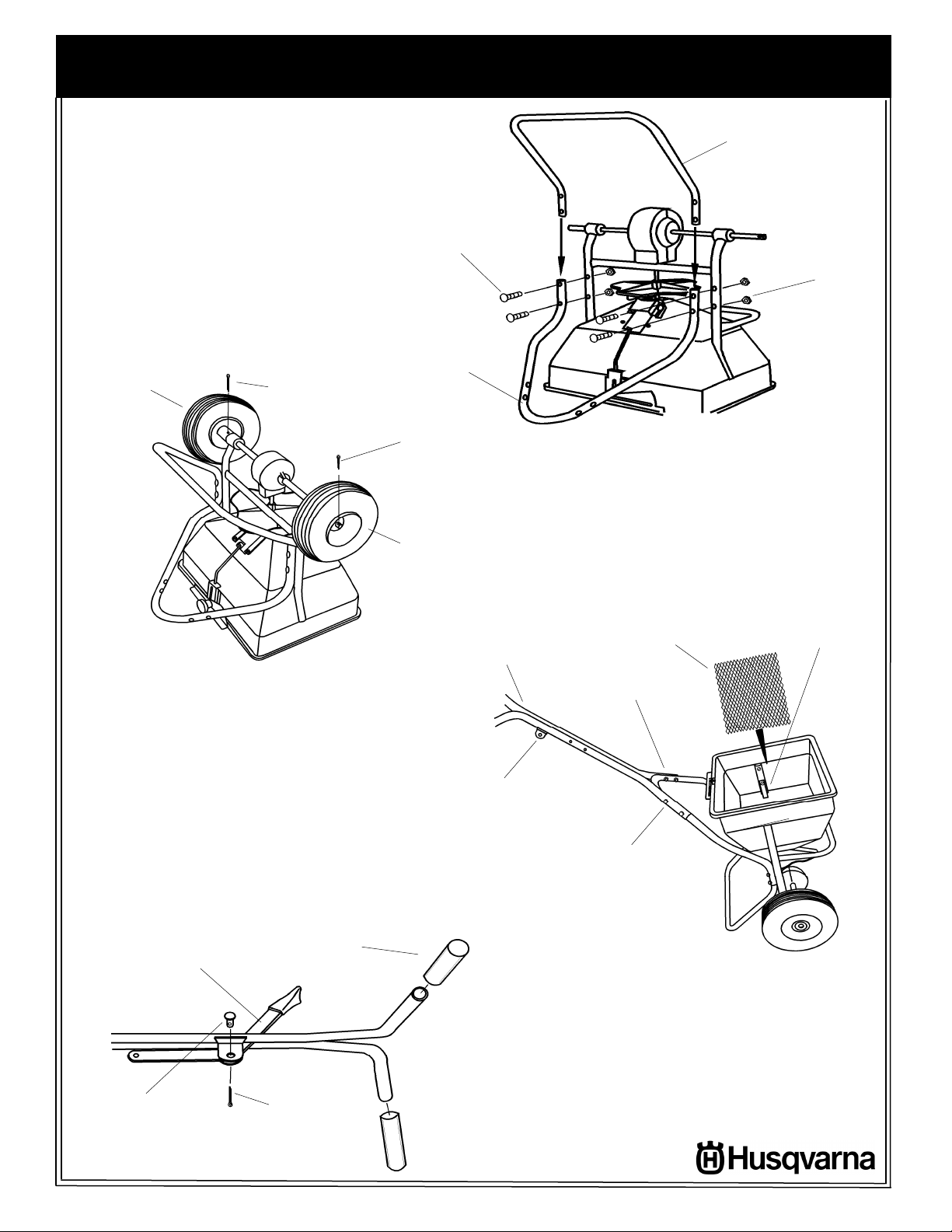
1.
components from carton and
place hopper up-side down on
a padded surface as shown.
Insert ends of leg into handle
brace as shown and align
holes. Attach brace and leg to
frame using (4) 1/4-20 x 2 1/4”
hex bolts and locknuts.
Drive Wheel
Remove the spreader and
3/16 Dia. x
2” Cotter Pin
ASSEMBLY
ASSEMBLY
ASSEMBLYASSEMBLY
1/4-20 X 2”
Hex Bolt
Handle
Brace
Leg
1/4-20
LOCKNUT
3.
Turn spreader upright on
wheels. Insert screen into
hopper sliding it under the
screen clips. Attach the upper
handle assembly to handle
brace with the handle lever
brackets facing as shown.
Secure with (4) 1/4-20 x 1 1/2”
hex bolts and locknuts.
5/32 Dia. x
1 1/4” Cotter
Pin
Free Turning
Wheel
NOTE POSITION OF
LEVER BRACKETS
2.
Slide wheels onto end of axle with the
hub facing toward frame. Wheels are
identical to ease assembly. Align the hole in
the wheel hub and the hole in the axle as
shown. Secure drive wheel to axle with 3/16
dia. x 2” cotter pin. Insert 1/8 dia. x 1 1/4”
cotter pin in the hole near the end of axle to
retain free turning wheel.
Upper Handle
Assembly
1/4-20 X 1 1/2”
Hex Bolt
1/4-20 Locknut
Screen
Screen Clip
1/4 Dia.
Clevis Pin
Handle
Lever
3/32” Dia.
Cotter Pin
Handle
Grip
2
4.
Slide handle lever between
handle brackets as shown and
secure with (1) 1/4 dia. clevis pin and
3/32” dia. cotter pin. Make sure lever
pivots freely. Install handle grips
onto upper handle.
Soapy water
will ease installation. (Do not use
petroleum based products).
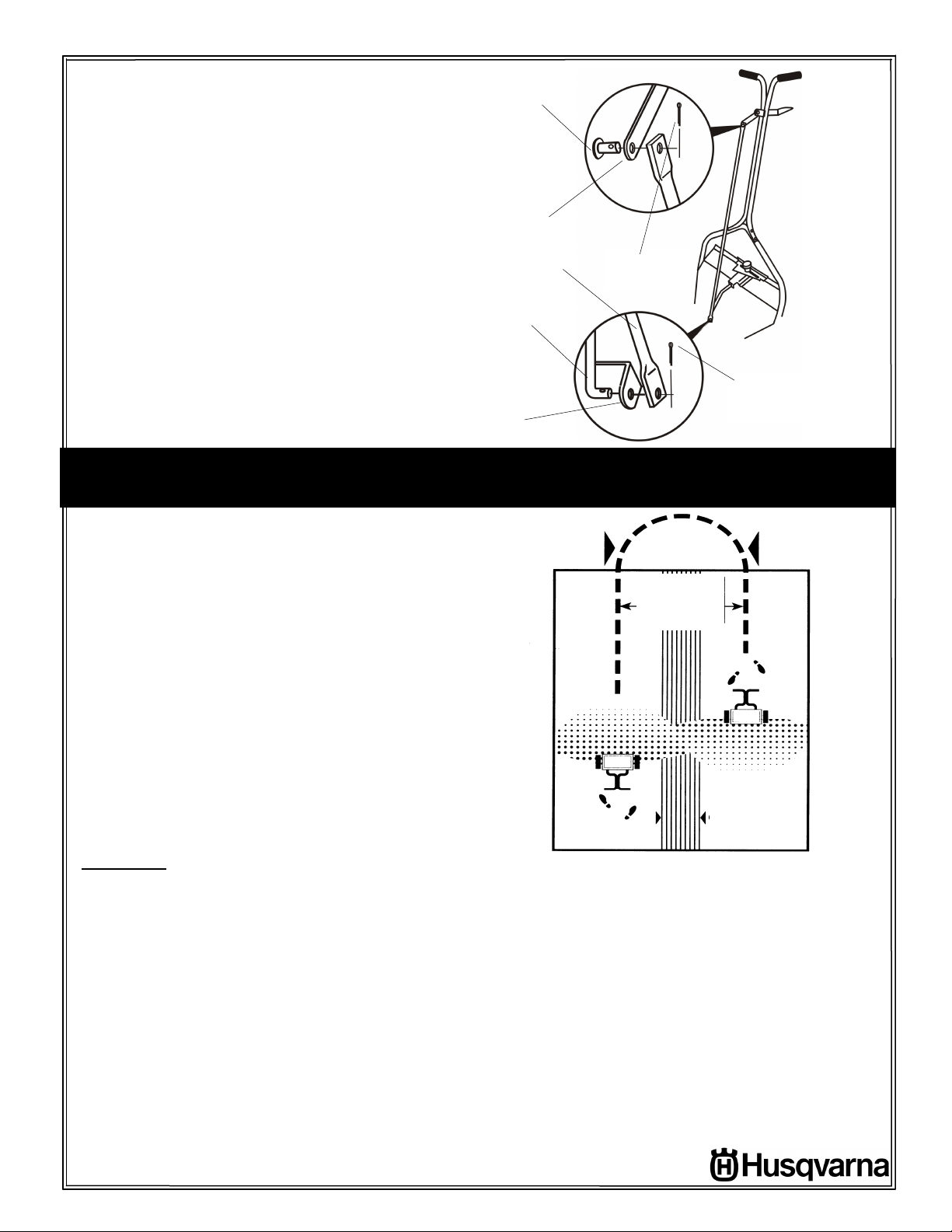
5.
Attach control tube to handle
lever with (1) 1/4 dia. clevis pin
and a 3/32” dia. cotter pin. Slip
opposite end of control tube over
lower control rod making sure
shutoff plate is between the lower
rod and the control tube. Secure
with a 3/32” dia. cotter pin.
1/4 Dia.
Clevis Pin
Handle
Lever
Control Tube
Lower Rod
Shutoff Plate
OPERATION
OPERATION
OPERATIONOPERATION
3/32” Dia.
Cotter Pin
3/32” Dia.
Cotter Pin
1.
Check the product package for the rate
setting, and recommended swath width. Loosen
rate control knob and slide rate plate to the
proper setting. The pattern is controlled by
loosening the two knobs on the discharge chute
and moving the chute closer or farther away
from the impeller (setting A, B, or C). See
“PATTERN ADJUSTMENT” for details.
2.
Always fill the spreader on the driveway or
sidewalk-not on the lawn. Make sure screen is in
hopper and spreader is in the “OFF” position
3.
Start spreader moving before opening port.
.
Close before stopping. Always push spreader,
never pull.
4.
Hold handle so top of spreader is level.
Tipping the spreader too far can cause uneven
spreading.
5.
The settings and swath widths on the product
label are recommended starting points. Always
check the delivery rate and pattern on a small
area before treating a large area. Actual delivery
rate can vary due to weather conditions,
operating variables, and condition of the
product being applied. See “HOW TO
DETERMINE SPREADER SETTINGS AND
SPREAD WIDTH” for details.
3
USE SWATH WIDTH
ON PACKAGE OR
ADJUST PER
OPERATOR’S
WALKING SPEED
OVERLAP
6.
Push spreader at a normal walking speed -
2 1/2 m.p.h. (18 feet in 5 seconds). Apply
header strips around area to be treated.
Space trips across the area as shown. Keep
material off flower beds, sidewalks, etc.
7.
When transporting spreader, make sure that
it is in the “OFF” position. Make sure handle
lever is locked using the hitch pin through the
hole in lever.
8.
Empty spreader after each use. Return
leftover material to its original container.
 Loading...