

Husqvarna 65RSW21HVA Owner’s Manual

Husqvarna
917.374780
(65RSW21HVA)
Owner's Manual
532186475 Rev. 6 10.17.03 BY Printed in U.S.A.
i_ Safe Operation Practices for Walk-Behind Mowers
IMPORTANT: THIS CUTTING MACHINE ISCAPABLEOFAMPUTATINGHANDSAND FEETAND THROWING OBJECTS. FAILURE
TOOBSERVE THE FOLLOWINGSAFETY INSTRUCTIONS COULD RESULTINSERIOUS INJURYOR DEATH.
I. GENERAL OPERATION
• Read, understand, and follow all instructions on the
machine and inthe manual(s) before starting. Be thor-
oughly familiar with the controls and the proper use of
the machine before starting.
• Do not put hands or feet near or under rotating parts.
Keep clear of the discharge opening at all times.
• Only allow responsible individuals, who are familiar
with the instructions, to operate the machine.
• Clear the area of objects such as rocks, toys, wire,
bones, sticks, etc., which could be picked up and thrown
by the blade.
• Be sure the area is clear of other people before mow-
ing. Stop machine if anyone enters the area.
• Do not operate the mower when barefoot or wearing
open sandals. Always wear substantial foot wear.
• Do not pull mower backwards unless absolutely nec-
essary. Always look down and behind before and while
moving backwards.
• Do not operate the mower without proper guards,
plates, grass catcher or other safety protective devices
in place.
• See manufacturer's instructions for proper operation
and installation of accessories. Only use accessories
approved by the manufacturer.
• Stop the blade(s) when crossing gravel drives, walks,
or roads.
• Stop the engine (motor) whenever you leave the equip-
ment, before cleaning the mower or unclogging the
chute.
• Shutthe engine (motor)offand wait untilthe blade comes
to complete stop before removing grass catcher.
• Mow only in daylight or good artificial light.
• Do not operate the machine while under the influence
of alcohol or drugs.
• Never operate machine inwet grass. Always besure of
your footing: keep a firm hold on the handle and walk;
never run.
• Disengage the self-propelled mechanism or drive clutch
on mowers so equipped before starting the engine (mo-
tor).
• If the equipment should start to vibrate abnormally,
stop the engine (motor) and check immediately for the
cause. Vibration is generally a warning of trouble.
• Always wear safety goggles or safety glasses with side
shields when operating mower.
II. SLOPE OPERATION
Slopes are a major factor related to slip and fall accidents
which can result in severe injury. All slopes require extra
caution. If you feel uneasy on a slope, do not mow it.
DO:
• Mow acrossthe face of slopes:never upand down. Exer-
cise extreme caution when changing direction on slopes.
• Remove obstacles such as rocks, tree limbs, etc.
• Watch for holes, ruts, or bumps. Tall grass can hide
obstacles.
SAFETY RULES
DO NOT:
• Do not trim near drop-offs, ditches or embankments.
The operator could lose footing or balance.
• Do not trim excessively steep slopes.
• Do not mow onwet grass. Reduced footing could cause
slipping.
III. CHILDREN
Tragic accidents can occur if the operator is not alert to
the presence of children. Children are often attracted to
the machine and the mowing activity. Never assume that
children will remain where you last saw them.
• Keep children out of the trimming area and under the
watchful care of another responsible adult.
• Be alert and turn machine off if children enter the
area.
• Before and while walking backwards, look behind and
down for small children.
• Never allow children to operate the machine.
• Use extra care when approaching blindcorners, shrubs,
trees, or other objects that may obscure vision.
IV. SERVICE
Use extra care in handling gasoline and other fuels.
They are flammable and vapors are explosive.
- Use only an approved container.
- Never remove gas cap or add fuel with the
engine running. Allow engine to cool before
refueling. Do not smoke.
- Never refuel the machine indoors.
- Never store the machine or fuel container inside
where there is an open flame, such as a water
heater.
Never run a machine inside a closed area.
Never make adjustments or repairs with the engine
(motor) running. Disconnect the spark plug wire, and
keep the wire away from the plug to prevent accidental
starting.
• Keep nuts and bolts, especially blade attachement
bolts, tight and keep equipment in good condition.
• Never tamper with safety devices. Check their proper
operation regularly.
• Keep machine free of grass, leaves, or other debris
build-up. Clean oil or fuel spillage. Allow machine to
cool before storing.
• Stop and inspect the equipment if you strike an object.
Repair, if necessary, before restarting.
• Never attempt to make wheel height adjustments while
the engine (motor) is running.
• Grass catcher components are subject to wear, dam-
age, and deterioration, which could expose moving
parts or allow objects to be thrown. Frequently check
components and replace with manufacturer's recom-
mended parts, when necessary.
• Mower blades are sharp and can cut. Wrap the blade(s)
or wear gloves, and use extra caution when servicing
them.
Do not change the engine governor setting or overspeed
2
the engine.
portant safety precautions. It means
CAUTION!!! BECOME ALERT!!! YOUR
Look for this symbol to point out im-
SAFETY IS INVOLVED,
CAUTION: Always disconnect spark plug
spark plug in order to prevent accidental
wireand placewirewhere it cannotcontact
starting when setting up, transporting,
adjusting or making repairs.
WARNING: Engine exhaust, some of
components contain or emit chemi-
its constituents, and certain vehicle
cals known to the State of California
to cause cancer and birth defects or
other reproductive harm.
WARNING: Battery posts,terminals and
lead compounds, chemicals known to
related accessories contain lead and
the State of California to cause cancer
and birth defects orother reproductive
harm. Wash hands after handling.
CAUTION: Muffler and other engine
parts become extremely hot during
operation and remain hot after engine
has stopped.To avoid severe burns on
contact, stay away from these areas.
CONGRATULATIONS on your purchase of a new lawn
mower. Ithas been designed, engineered and manufactured
togive you the best possible dependability and performance.
Should you experience any problem you cannot easily
remedy, please contact your nearest authorized service
center/department. We have competent, well-trained
technicians and the proper tools to service or repair this
lawn mower.
Please read and retain this manual. The instructions will
enable you to assemble and maintain your lawn mower
properly. Always observe the "SAFETY RULES".
SERIAL
NUMBER:
DATE OF PURCHASE:
THE MODEL AND SERIAL NUMBERS WILL BE FOU ND
ON A DECAL ATTACH EDTOTHE REAR OFTHE LAWN
MOWER HOUSING.
YOU SHOULD RECORD BOTH SERIAL NUMBER AND
DATE OF PURCHASE AND KEEP IN A SAFE PLACE
FOR FUTURE REFERENCE.
PRODUCT SPECIFICATIONS
Gasoline Capacity 1.0 Quarts
and Type: (Unleaded Regular Only)
Oil Type (API-SF-SJ): SAE 10W-30
Oil Capacity: 18.5 Ounces
Spark Plug: NGK BPR6ES (Gap: .030")
Valve Clearance: Intake: 0.015 mm
(_+0.04 mm) Exhaust: 0.020 mm
Blade Bolt Torque: 35-40 ft. Ibs.
CUSTOMER RESPONSIBILITIES
• Read and observe the safety rules.
• Follow a regular schedule in maintaining, caring for and
using your lawn mower.
• Follow the instructions under "Maintenance" and "Stor-
age" sections of this owner's manual.
TABLE OF CONTENTS
SAFETY RULES ......................................................... 2-3
PRODUCT SPECIFICATIONS ....................................... 3
CUSTOMER RESPONSIBILITIES ................................. 3
ASSEMBLY ................................................................. 4-5
OPERATION ............................................................. 6-11
MAINTENANCE SCHEDULE ...................................... 12
MAINTENANCE ...................................................... 12-14
SERVICE AND ADJUSTMENTS ............................ 14-16
STORAG E ............................................................... 16-17
TROUBLESHOOTING ................................................. 18
REPAIR PARTS ....................................................... 19-23
WARRANTY ................................................................. 24
3
ASSEMBLY
Read these instructionsandthismanual initsentirety before
you attempt to assemble or operate your new lawn mower.
IMPORTANT: THIS LAWN MOWER IS SHIPPED WITH-
OUT OIL OR GASOLINE INTHE ENGINE.
Your new lawn mower has been assembled at the factory
with the exception of those parts left unassembted for ship-
ping purposes. All parts such as nuts, washers, bolts, etc.,
necessary to complete the assembly have been placed in
the parts bag.To ensure safe and proper operation of your
lawn mower, all parts and hardware you assemble must
be tightened securely. Use the correct tools as necessary
to ensure proper tightness.
TO REMOVE LAWN MOWER FROM CARTON
1. Remove loose parts included with mower.
2. Cut down two end corners of carton and lay end panel
down flat.
3. Remove all packing materials except padding between
upper and lower handle and padding holding operator
presence control bar to upper handle.
4. Roll lawn mower out of carton and check carton thor-
ougly for additional loose parts.
HOWTO SET UPYOUR LAWN MOWER
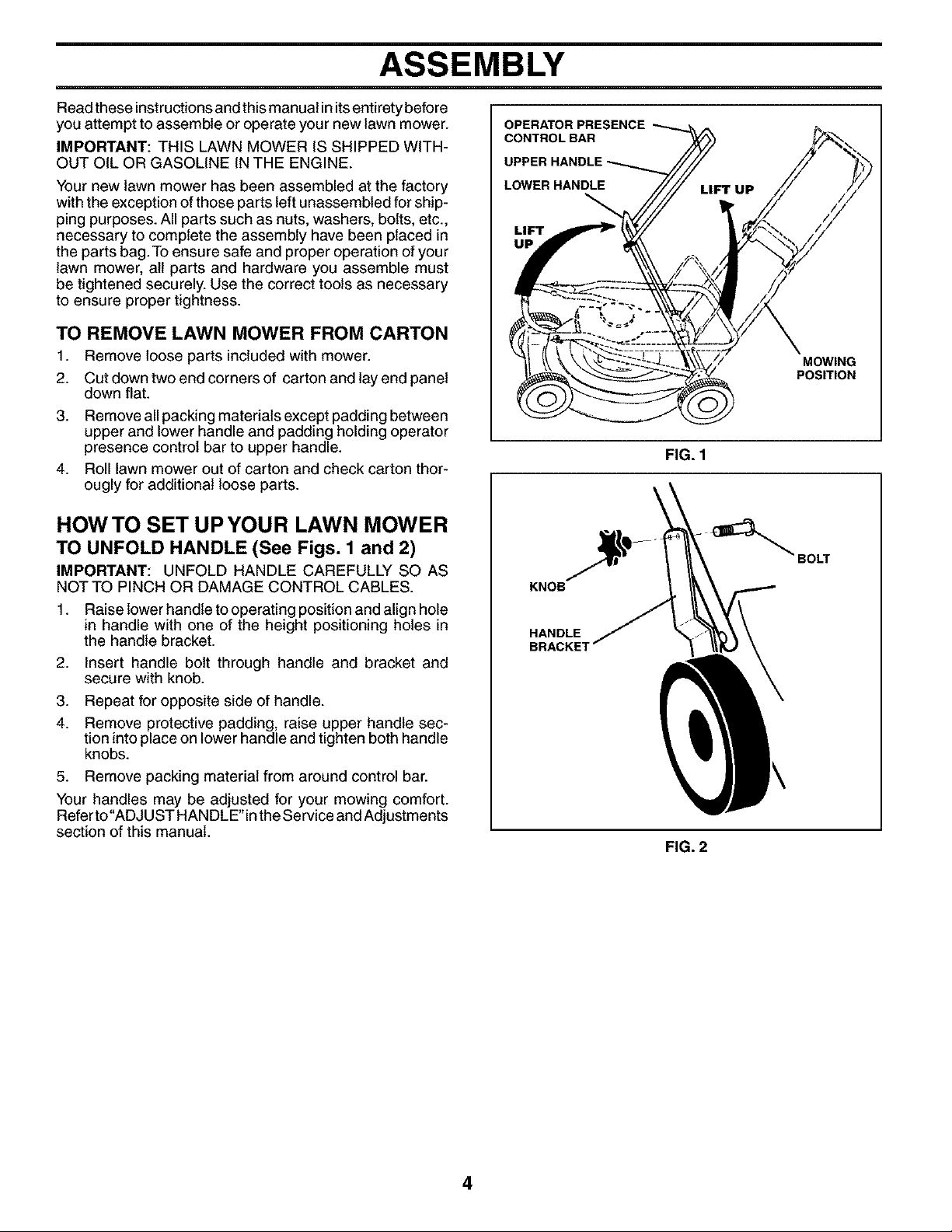
TO UNFOLD HANDLE (See Figs. 1 and 2)
IMPORTANT: UNFOLD HANDLE CAREFULLY SO AS
NOT TO PINCH OR DAMAGE CONTROL CABLES.
1. Raise lower handle to operating position and align hole
in handle with one of the height positioning holes in
the handle bracket.
2. Insert handle bolt through handle and bracket and
secure with knob.
3. Repeat for opposite side of handle.
4. Remove protective padding, raise upper handle sec-
tion into place on lower handle and tighten both handle
knobs.
5. Remove packing material from around control bar.
Your handles may be adjusted for your mowing comfort.
Refer to"ADJUST HANDLE" inthe Service and Adjustments
section of this manual.
OPERATOR PRESENCE_
CONTROL BAR
UPPER
LOWER HANDLE
MOWING
POSITION
FIG. 1
\
_ BOLT
KNOB
HANDLE
BRACKE1
FIG. 2
4
ASSEMBLY
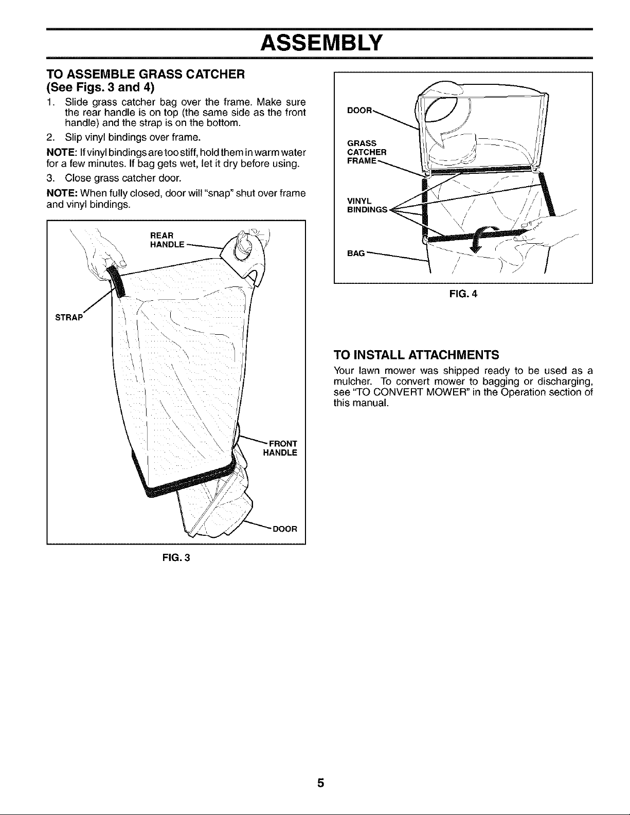
TO ASSEMBLE GRASS CATCHER
(See Figs. 3 and 4)
1. Slide grass catcher bag over the frame. Make sure
the rear handle is on top (the same side as the front
handle) and the strap is on the bottom.
2. Slip vinyl bindings over frame.
NOTE: Ifvinylbindings aretoostiff,holdthem inwarm water
for a few minutes. Ifbag gets wet, let it dry before using.
3. Close grass catcher door.
NOTE: When fully closed, door will"snap" shut over frame
and vinyl bindings.
REAR
STRAP
DOOR_
GRASS
CATCHER
VINYL
BINDING:
/
/
/
FIG. 4
\
\
TO INSTALL ATTACHMENTS
Your lawn mower was shipped ready to be used as a
mulcher. To convert mower to bagging or discharging,
see "TO CONVERT MOWER" in the Operation section of
this manual.
H_ANDLE
DOOR
FIG. 3
5
OPERATION
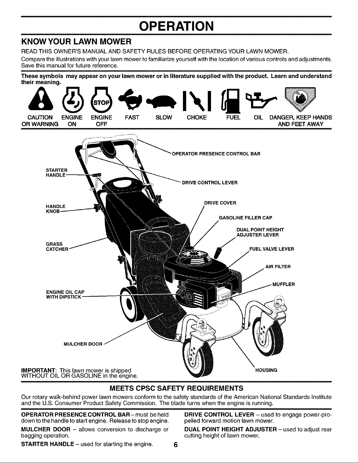
KNOWYOUR LAWN MOWER
READ THIS OWNER'S MANUAL AND SAFETY RULES BEFORE OPERATING YOUR LAWN MOWER.
Compare the illustrations with your lawn mower to familiarize yourself with the location of various controls and adjustments.
Save this manual for future reference.
These symbols may appear on your lawn mower or in literature supplied with the product. Learn and understand
their meaning.
CAUTION ENGINE ENGINE FAST SLOW CHOKE FUEL OIL DANGER, KEEP HANDS
OR WARNING ON OFF AND FEET AWAY
"OPERATOR PRESENCE CONTROL BAR
STARTER
DRIVE CONTROL LEVER
HANDLE
GRASS
ENGINE OIL CAP
WITH DIPSTICK"
MULCHER DOOR
IMPORTANT: This lawn mower is shipped
WITHOUT OIL OR GASOLINE in the engine.
DRIVE COVER
GASOLINE FILLER CAP
DUAL POINT HEIGHT
ADJUSTER LEVER
FUEL VALVE LEVER
AIR FILTER
HOUSING
MEETS CPSC SAFETY REQUIREMENTS
Our rotary walk-behind power lawn mowers conform to the safety standards of the American National Standards Institute
and the U.S. Consumer Product Safety Commission. The blade turns when the engine is running.
OPERATOR PRESENCE CONTROL BAR - must be held
down to the handle to start engine. Release to stop engine.
MULOHER DOOR - allows conversion to discharge or
bagging operation.
DRIVE CONTROL LEVER - used to engage power-pro-
pelled forward motion lawn mower.
DUAL POINT HEIGHT ADJUSTER - used to adjust rear
cutting height of lawn mower.
STARTER HANDLE - used for starting the engine. 6
OPERATION
=,_,-'== in severe eye damage. Always wear safety glasses or eye shields while operating your lawn mower or
I The operation of any lawn mower can result in foreign objects thrown into the eyes, which can result
performing any adjustments or repairs. We recommend standard safety glasses or a wide vision safety
mask over spectacles.
HOWTO USEYOUR LAWN MOWER
ENGINE SPEED
The engine speed was set at the factory for optimum per-
formance. Speed is not adjustable.
ENGINE ZONE CONTROL
CAUTION: Federal regulations require
an engine control to be installed on this
lawn mower inorder to minimizethe risk
of blade contact injury. Do not under
A
Your lawn mower isequipped withan operator presence
control bar which requires the operator to be positioned
behind the lawn mower handle to start and operate the
lawn mower.
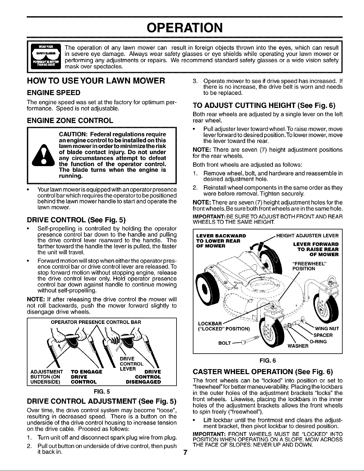
DRIVE CONTROL (See Fig. 5)
• Self-propelling is controlled by holding the operator
presence control bar down to the handle and pulling
the drive control lever rearward to the handle. The
farther toward the handle the lever is pulled, the faster
the unit will travel.
Forward motion will stop when either the operator pres-
ence control bar or drive control lever are released. To
stop forward motion without stopping engine, release
the drive control lever only. Hold operator presence
control bar down against handle to continue mowing
without self-propelling.
NOTE: If after releasing the drive control the mower will
not roll backwards, push the mower forward slightly to
disengage drive wheels.
any circumstances attempt to defeat
the function of the operator control.
The blade turns when the engine is
running.
OPERATOR PRESENCE CONTROLBAR
3. Operate mower to see if drive speed has increased. If
there is no increase, the drive belt is worn and needs
to be replaced.
TO ADJUST CUTTING HEIGHT (See Fig. 6)
Both rear wheels are adjusted by a single lever on the left
rear wheel.
• Pull adjuster lever toward wheel.To raise mower, move
lever forward to desired position.To lower mower, move
the lever toward the rear.
NOTE: There are seven (7) height adjustment positions
for the rear wheels.
Both front wheels are adjusted as follows:
1. Remove wheel, bolt, and hardware and reassemble in
desired adjustment hole.
2. Reinstall wheel components in the same order as they
were before removal. Tighten securely.
NOTE: There are seven (7) height adjustment holes for the
front wheels. Be sure both front wheels are in the same hole.
IMPORTANT: BE SURE TO ADJUST BOTH FRONT AND REAR
WHEELS TO THE SAME HEIGHT.
LEVER BACKWARD
TO LOWER REAR
OF MOWER
LOG
("LOCKED" POSITION)
JUSTER LEVER
LEVER FORWARD
TO RAISE REAR
OF MOWER
"FREEWHEEl'
POSITION
DRIVE
CONTROL
ADJUSTMENT TO ENGAGE DRIVE
SUTTON (ON DRIVE CONTROL
UNDERSIDE) CONTROL DISENGAGED
FIG. 5
DRIVE CONTROL ADJUSTMENT (See Fig. 5)
Over time, the drive control system may become "loose",
resulting in decreased speed. There is a button on the
underside of the drive control housing to increase tension
on the drive cable. Proceed as follows:
1. Turn unit off and disconnect spark plug wire from plug.
2. Pull out button on underside of drive control, then push
it back in.
LEVER
WASHER
O-RING
FIG. 6
CASTER WHEEL OPERATION (See Fig. 6)
The front wheels can be "locked" into position or set to
"freewheel" for better maneuverability. Placing the lockbars
in the outer holes of the adjustment brackets "locks" the
front wheels. Likewise, placing the lockbars in the inner
holes of the adjustment brackets allows the front wheels
to spin freely ("freewheel").
• Lift Iockbar until the frontmost end clears the adjust-
ment bracket, then pivot lockbar to desired position.
IMPORTANT: FRONT WHEELS MUST BE "LOCKED" INTO
POSITION WHEN OPERATINGON A SLOPE.MOW ACROSS
THE FACEOF SLOPES: NEVER UP AND DOWN.
7
OPERATION
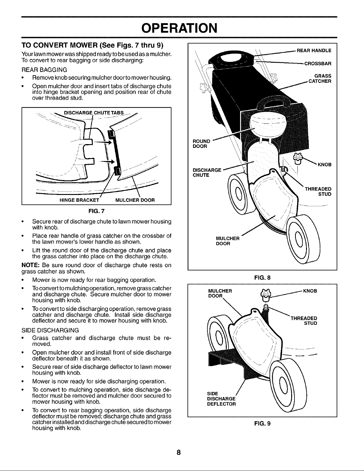
TO CONVERT MOWER (See Figs. 7 thru 9)
Your lawn mower was shipped ready tobe used as a mulche r.
To convert to rear bagging or side discharging:
REAR BAGGING
Remove knob securing mulcher door to mower housing.
Open mulcher door and insert tabs of discharge chute
into hinge bracket opening and position rear of chute
over threaded stud.
L-- j/
HINGE BRACKET MULCHER DOOR
FIG. 7
HANDLE
GRASS
ROUND
DOOR
DISCHARGE
CHUTE
THREADED
STUD
• Secure rear of discharge chute to lawn mower housing
with knob.
• Place rear handle of grass catcher on the crossbar of
the lawn mower's lower handle as shown.
• Lift the round door of the discharge chute and place
the grass catcher into place on the discharge chute.
NOTE: Be sure round door of discharge chute rests on
grass catcher as shown.
• Mower is now ready for rear bagging operation.
• Toconvert to mulching operation, remove grass catcher
and discharge chute. Secure mulcher door to mower
housing with knob.
• Toconvert to side discharging operation, remove grass
catcher and discharge chute. Install side discharge
deflector and secure it to mower housing with knob.
SIDE DISCHARGING
• Grass catcher and discharge chute must be re-
moved.
• Open mulcher door and install front of side discharge
deflector beneath it as shown.
• Secure rear of side discharge deflector to lawn mower
housing with knob.
• Mower is now ready for side discharging operation.
• To convert to mulching operation, side discharge de-
flector must be removed and mulcher door secured to
mower housing with knob.
• To convert to rear bagging operation, side discharge
deflector must be removed; discharge chute and grass
catcher installed and discharge chute secured to mower
housing with knob.
MULCHER
DOOR
FIG. 8
MULCHER
DOOR
THREADED
STUD
SIDE
DISCHARGE
DEFLECTOR
FIG. 9
8
 Loading...