

Page 1
Operator's
2008-02
Pressure Washer
5525PW, 6027PW,
9032PW, 1340PW
Manual
O0807301
Operator's Manual
Page 2

English — 1
CONTENTS
Contents
CONTENTS . . . . . . . . . . . . . . . . . . . . . . . . . . . .1
Contents . . . . . . . . . . . . . . . . . . . . . . . . . . . . . .1
KEY TO SYMBOLS . . . . . . . . . . . . . . . . . . . . .2
Symbols in the Operator’s Manual . . . . . . . . .2
INTRODUCTION . . . . . . . . . . . . . . . . . . . . . . .3
Dear Customer . . . . . . . . . . . . . . . . . . . . . . . . .3
WHAT IS WHAT? . . . . . . . . . . . . . . . . . . . . . . .4
What is what on the pressure washer . . . . . .4
FREQUENTLY ASKED QUESTIONS . . . . . . . .5
How do I start my pressure washer? . . . . . . .5
What type of oil do I use? . . . . . . . . . . . . . . .5
Why don’t I have any water pressure? . . . . . .5
How do I get high pressure? . . . . . . . . . . . . . .5
How do I get the soap suction to work? . . . .5
Why doesn’t the pressure washer apply
detergents with high pressure? . . . . . . . . . . .5
What maintenance do I need to perform
on my pressure washer? . . . . . . . . . . . . . . . . .5
Where can I buy accessories for my
pressure washer? . . . . . . . . . . . . . . . . . . . . . . .5
SAFETY GUIDELINES . . . . . . . . . . . . . . . . . . .6
Important Safety Guidelines . . . . . . . . . . . . . .6
PRE-OPERATION . . . . . . . . . . . . . . . . . . . . . . .8
Unpacking . . . . . . . . . . . . . . . . . . . . . . . . . . . .8
Assembly . . . . . . . . . . . . . . . . . . . . . . . . . . . . . .8
Trigger Safety Latch . . . . . . . . . . . . . . . . . . . .10
OPERATION . . . . . . . . . . . . . . . . . . . . . . . . . .11
1. Surface preparation . . . . . . . . . . . . . . . . . .11
2. Start Up . . . . . . . . . . . . . . . . . . . . . . . . . . .11
3. Initial High Pressure Rinse . . . . . . . . . . . . .11
Pressure Adjustment . . . . . . . . . . . . . . . .12
Adjusting the Spray Fan Angle . . . . . . .12
Angle to the Cleaning Surface . . . . . . . .12
Distance from Cleaning Surface . . . . . . .13
How to Avoid Damaging Surfaces . . . . .13
4. Detergent Application . . . . . . . . . . . . . . .13
Detergents . . . . . . . . . . . . . . . . . . . . . . . .13
General Cleaning Tips . . . . . . . . . . . . . . .14
5. Cleaning Power . . . . . . . . . . . . . . . . . . . . .14
6. Final Rinse . . . . . . . . . . . . . . . . . . . . . . . . .14
7. Shutdown . . . . . . . . . . . . . . . . . . . . . . . . . .14
Pressure Relief Procedure . . . . . . . . . . . . . . .14
8. Storage . . . . . . . . . . . . . . . . . . . . . . . . . . . .14
Long Term Storage Instructions
(More than 30 days in storage) . . . . . . .14
Tips for Extending the Life of Your
Pressure Washer . . . . . . . . . . . . . . . . . . .15
MAINTENANCE . . . . . . . . . . . . . . . . . . . . . . .16
Engine Oil Changing Instructions . . . . . . . . .16
Check Pump Oil and Pump Oil Changing . .17
MAINTENANCE SCHEDULE . . . . . . . . . . . .18
TECHNICAL AND CONSUMER
INFORMATION . . . . . . . . . . . . . . . . . . . . . . .19
TROUBLESHOOTING CHART . . . . . . . . . . .20
SERVICE RECORD . . . . . . . . . . . . . . . . . . . .22
CART PARTS LIST . . . . . . . . . . . . . . . . . . . . .23
5525PW Cart . . . . . . . . . . . . . . . . . . . . . . . . . .23
6027PW Cart . . . . . . . . . . . . . . . . . . . . . . . . . .24
9032PW Cart . . . . . . . . . . . . . . . . . . . . . . . . . .25
1340PW Cart . . . . . . . . . . . . . . . . . . . . . . . . . .25
PUMP PART LIST . . . . . . . . . . . . . . . . . . . . .26
5525PW Pump . . . . . . . . . . . . . . . . . . . . . . . .26
6027PW Pump . . . . . . . . . . . . . . . . . . . . . . . .27
9032PW Pump . . . . . . . . . . . . . . . . . . . . . . . .28
1340PW Pump . . . . . . . . . . . . . . . . . . . . . . . .29
PRODUCT REGISTRATION NOTICE . . . . . .31
WARRANTY . . . . . . . . . . . . . . . . . . . . . . . . .32
IN469200AV 2/08
Page 3
2 — English
Safety Guidelines
This manual contains information that is very
important to know and understand. This
information is provided for SAFETY and to PREVENT
EQUIPMENT PROBLEMS. To help recognize this
information, observe the following symbols.
Warning indicates a potentially
hazardous situation which, if not
avoided, COULD result in death or serious injury.
Caution indicates a potentially
hazardous situation which, if not
avoided, MAY result in minor or moderate injury.
Notice indicates important
information, that if not followed,
may cause damage to equipment.
NOTE: Information that requires special attention.
KEY TO SYMBOLS
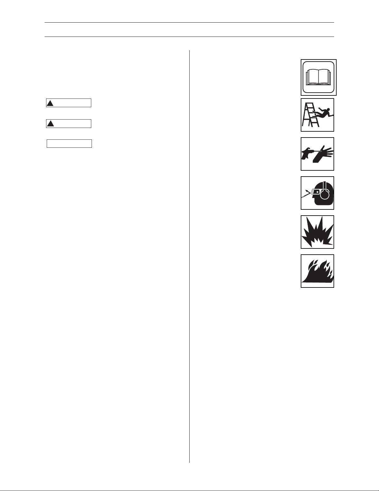
Symbols in the Operator’s Manual
Please read the operator’s manual
carefully and make sure you
understand the intructions before
using the tool.
DO NOT overreach or stand on
unstable support. Keep good footing
and balance at all times.
Risk of injection or severe injury. Keep
clear of nozzle.
ALWAYS wear safety glasses or
goggles and protective equipment
(hearing protection, gloves, rubber
boots, protective clothing) when
operating or performing
maintenance.
Risk of explosion.
Risk of fire.
!
WARNING
!
CAUTION
NOTICE
Page 4

English — 3
INTRODUCTION
Dear Customer,
Congratulations on your choice to buy a Husqvarna product! Husqvarna is based on a tradition
that dates back to 1689, when the Swedish King Charles XI ordered the construction of a factory
on the banks of the Husqvarna River, for production of muskets. The location was logical, since
waterpower was harnessed from the Husqvarna River to create the water-powered plant. During
the more than 300 years of being, the Husqvarna factory has produced a lot of different products,
from wood stoves to modern kitchen appliances, sewing machines, bicycles, motorcycles, etc. In
1956, the first motor driven lawn mowers appeared, followed by chain saws in 1959, and it is
within this area Husqvarna is working today.
Today, Husqvarna is one of the leading manufacturers in the world of forest and garden products,
with quality as our highest priority. The business concept is to develop, manufacture and market
motor driven products for forestry and gardening, as well as for the building and construction
industry. Husqvarna’s aim is also to be in the front edge according to ergonomics, usability, security
and environmental protection. That is the reason why we have developed many different features
to provide our products within these areas.
We are convinced that you will appreciate, with great satisfaction, the quality and performance of
our product for a very long time to come. The purchase of one of our products gives you access to
professional help with repairs and service whenever this may be necessary. If the retailer who sells
your machine is not one of our authorized dealers, ask for the address of your nearest service
workshop.
It is our wish that you will be satisfied with your product and that it will be your companion for a
long time. Think of this operator’s manual as a valuable document. By following its’ content (using,
service, maintenance, etc) the life span and the second-hand value of the machine can be
extended. If you will sell this machine, make sure that the buyer will get the operator’s manual.
Thank you for using a Husqvarna product.
Husqvarna AB has a policy of continuous product development and therefore reserves the right to
modify the design and appearance of products without prior notice.
For customer assistance call 704-921-7000 or contact us at our website: www.husqvarna.com
Page 5
4 — English
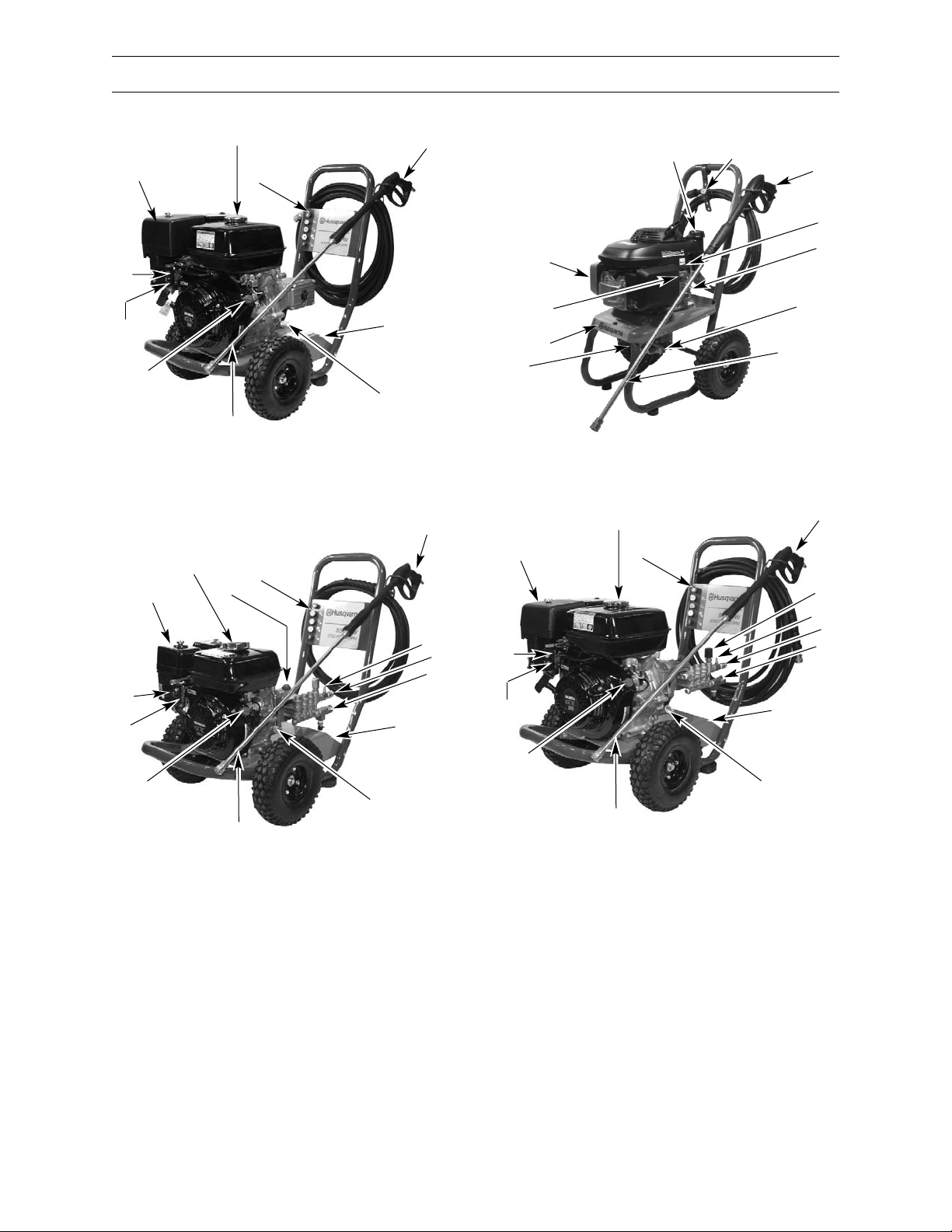
WHAT IS WHAT?
1 Serial Number/ Product Decal
2 Tip Holder with Spray Tips
3 Injection Tube Barb
4 Gun with Trigger
5 Lance
6 Inlet Connection for High Pressure Hose
7 Inlet Connection for Garden Hose
8 Engine Oil Fill
9 Engine switch - On/Off
10 Air Filter
11 Choke
12 Fuel Tank
13 Pressure Adjusting Knob
14 Fuel Valve - On/Off
2
4
6027PW
1
5
7
9
10
11
12
14
8
6
3
7
2
9032PW
1
5
9
10
11
12
14
8
6
3
7
1
2
4
5
6
9
10
11
12
5525PW
7
8
13
4
1340PW
2
1
5
9
10
11
12
14
8
4
Page 6

English — 5
FREQUENTLY ASKED QUESTIONS
How do I start my pressure
washer?
1. Make sure you have gas and oil in the engine.
2. Turn the water on, then squeeze the trigger on
the gun to make sure the water will flow
smoothly out of the nozzle or tip.
3. Put the engine throttle control in the
“Fast/Start” position. Set the fuel valve to “ON”
Set the On/Off switch to “ON” (if applicable).
4. Close the choke.
5. Squeeze and hold the trigger (to relieve any
back pressure in the pump) while pulling the
starter cord.
6. If the engine does not start after three tries, see
Troubleshooting Section (Pages 20-21).
What type of oil do I use?
ENGINE
THE ENGINE DOES NOT COME FILLED WITH OIL. For
engine oil types and quantities refer to Pages 16
and 19 of this manual and also refer to the included
engine owner’s manual for oil changing instructions.
PUMP
See Page 17 for pump oil types and quantities.
Please note the 5525PW model has a pump that is
sealed and does not require service.
Why don’t I have any water
pressure?
• Is the water hose attached to the pressure
washer?
• Is the water turned on?
• Check for any kinks, leaks, or blockage in the
hoses, fittings, or the nozzle.
• Is the inlet filter screen free of debris? Check and
remove debris if needed.
• Is the quick connect tip in place? (See Page 9.)
How do I get high pressure?
• Use any color tip except black. The black tip is
only used for low pressure detergent application.
How do I get the soap
suction to work?
For Detergent Tanks:
1. Attach clear plastic tube to plastic barb on
detergent tank (see Figure 2).
2. Fill detergent tank with detergent formulated
for use with pressure washers.
3. Install the black spray tip to apply low pressure
detergent.
For Other Units:
1. Attach clear plastic tube to brass barb on pump
(see Figure 2).
2. Put the other filter end of the clear tube into
the detergent container.
3. Install the black spray tip to apply low pressure
detergent.
Why doesn’t the pressure
washer apply detergents
with high pressure?
The reason you don’t apply detergents with high
pressure is that the detergents “bounce” off the
cleaning surface as fast as you apply them.
Detergent is only effective when you allow it time
to work on the surface of whatever you are
cleaning. You can only apply detergent at low
pressure, wait 1-3 minutes to allow it to work, and
rinse the surface with high pressure.
What maintenance do I
need to perform on my
pressure washer?
1. After turning off the pressure washer and the
water, depressurize the hose by triggering the
gun.
2. Remove the garden hose and high pressure hose
from the pump.
3. Pull the start rope slowly five times to purge
water from the pump. This will help protect the
pump from damage.
4. DO NOT store your pressure washer in an area
where the temperature will drop below 32˚F /
0˚C) unless pressure washer is properly
winterized (see Page 15).
Where can I buy accessories
for my pressure washer?
• Call your local Husqvarna Dealer.
Page 7
6 — English
SAFETY GUIDELINES
Important Safety Instructions
SAVE THESE INSTRUCTIONS
The engine exhaust from
this product contains chemicals
known to the State of California to cause cancer,
birth defects or other reproductive harm.
When using this product, basic precautions should
ALWAYS be followed, including the following:
• Read all instructions before using
the product.
• To reduce the risk of injury, close
supervision is necessary when the
product is used near children.
• Follow all safety codes as well as the Occupational
Safety and Health Act (OSHA).
• Ensure safety devices are operating properly
before each use. DO NOT remove or modify any
part of the gun or unit.
• Know how to stop this product and bleed
pressure quickly. Be thoroughly familiar with the
controls.
• Stay alert – watch what you are doing.
• DO NOT operate the product when fatigued or
under the influence of alcohol or drugs.
• Keep operation area clear of all persons.
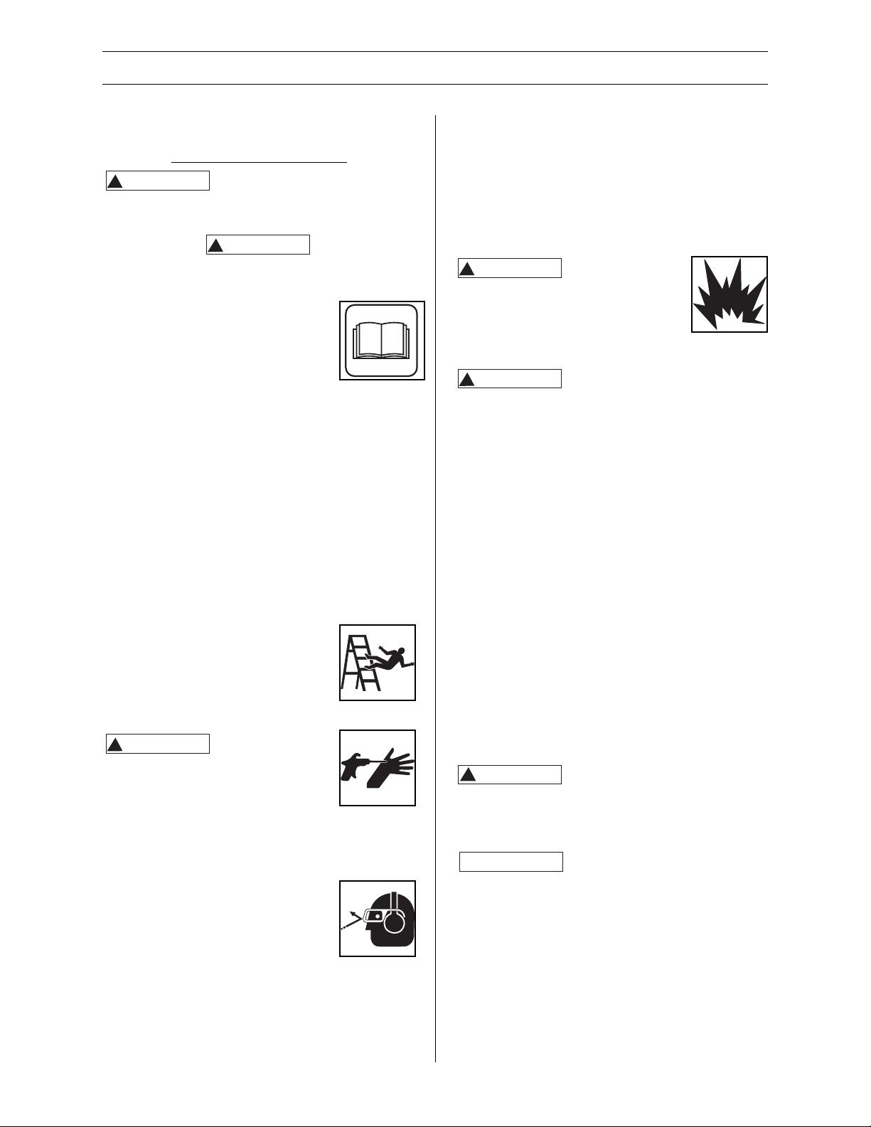
• DO NOT overreach or stand on
unstable support. Keep good
footing and balance at all times.
• Follow the maintenance instructions
specified in the manual.
Risk of injection or
severe injury. Keep
clear of nozzle. DO NOT discharge
streams at persons. This product is to
be used only by trained operators.
ALWAYS remove lance from gun before
cleaning debris from tip.
• Keep clear of nozzle. NEVER direct high pressure
spray at a person, animal, or yourself.
• ALWAYS wear safety glasses or
goggles and protective equipment
(hearing protection, gloves, rubber
boots, protective clothing) when
operating or performing
maintenance.
• NEVER put hand or fingers over the spray tip
while operating the unit.
• NEVER try to stop or deflect leaks with any body
part.
• ALWAYS engage the trigger safety latch in the
safe position when spraying is stopped even if
only for a few moments.
• ALWAYS follow detergent manufacturer’s label
recommendations for proper use of detergents.
ALWAYS protect eyes, skin, and respiratory
system from detergent use.
DO NOT use
pressure that
exceeds the operating pressure of any
of the parts (hoses, fittings, etc.) in
the pressurized system. Ensure all
equipment and accessories are rated
to withstand the maximum working
pressure of the unit.
Explosion hazard.
• NEVER spray flammable liquids or use pressure
washer in areas containing combustible dust,
liquids, or vapors.
• NEVER operate this machine in a closed building
or in or near an explosive environment.
• DO NOT remove fuel tank cap or fill fuel tank
while engine is hot or running (allow engine to
cool two minutes before refueling). ALWAYS fill
the tank slowly.
• NEVER disconnect the high pressure discharge
hose from the machine while the system is
pressurized. To depressurize machine, turn
power and water supply off, then press the gun
trigger 2-3 times.
• NEVER permanently engage the trigger
mechanism on the gun.
• NEVER operate the machine without all
components properly connected to the machine
(handle, gun/wand assembly, nozzle, etc.).
Keep hose away from sharp
objects. Bursting hoses may
cause injury. Examine hoses regularly and replace if
damaged. DO NOT attempt to mend a damaged
hose.
Equipment damage.
• ALWAYS turn water supply “ON” before turning
pressure washer “ON.” Running pump dry causes
serious damage.
• DO NOT operate the pressure washer with the
inlet water screen removed. Keep screen clear of
debris and sediment.
• NEVER operate pressure washer with broken or
missing parts. Check equipment regularly and
repair or replace worn or damaged parts
immediately.
!
WARNING
!
WARNING
!
WARNING
!
WARNING
!
WARNING
!
CAUTION
NOTICE
Page 8

English — 7
SAFETY GUIDELINES
• Use only the nozzle supplied with this machine.
• NEVER leave the wand unattended while the
machine is running.
• NEVER tamper with the engine governor or
attempt to alter factory settings. Altering factory
settings could damage the unit and will void the
warranty.
• ALWAYS hold gun and wand firmly when
starting and operating the machine.
• NEVER allow the unit to run with the trigger
released (off) for more than two minutes.
Resulting heat buildup will damage the pump.
• NEVER store the pressure washer outdoors or
where it could freeze. Freezing temperatures can
seriously damage the pump.
• Release the trigger when changing from high to
low pressure modes. Failure to do so could result
in damage to the nozzle.
Page 9
8 — English
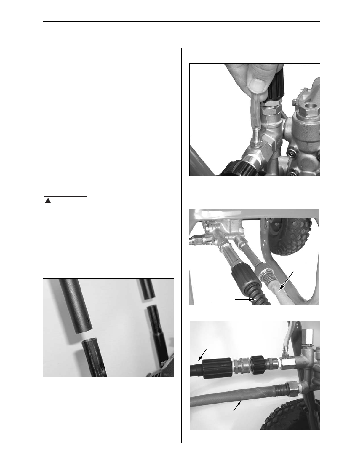
2. Connect clear plastic hose to brass barb on pump
(See Figure 2).
3. Secure garden hose (not included) to the inlet
connection on pump (See Figures 3 and 4).
PRE-OPERATION
UNPACKING
Remove the equipment and all parts from the
carton. The carton should contain the following.
• One pressure washer (pump, engine, cart base).
• One cart handle assembly.
• One spray gun.
• One lance.
• Two spray tips for Model 5525PW
Five spray tips for Models 1340PW, 6027PW and
9032PW
• One high pressure hose.
• One pack of nuts, bolts, and manuals.
• One bottle of engine oil.
If any parts are missing, Please contact your
Husqvarna dealer.
After unpacking the product, inspect it carefully for
any damage that may have occurred during transit.
Make sure to tighten fittings and bolts before using
the pressure washer.
DO NOT operate the unit if it’s
damaged during shipping,
handling, or use. Damage could result in bursting
and cause injury or property damage.
ASSEMBLY
Use 1/2” (13 mm) wrench to assemble pressure
washer. On model 5525PW use two adjustable or
7/16” wrenches.
1. Slide the handle assembly over the lower legs of
the cart base. Use the standard nut and bolt to
secure the legs. See Figure 1.
Figure 1 - Assemble Handle
Figure 2 - Connect hose to brass barb
Figure 3 - Secure garden hose
Garden Hose
High Pressure
Hose
Figure 4 - Connect high pressure hose to pump
Garden Hose
High Pressure
Hose
!
WARNING
Page 10
English — 9
4. Connect the high pressure hose to the pump outlet
(See Figure 4).
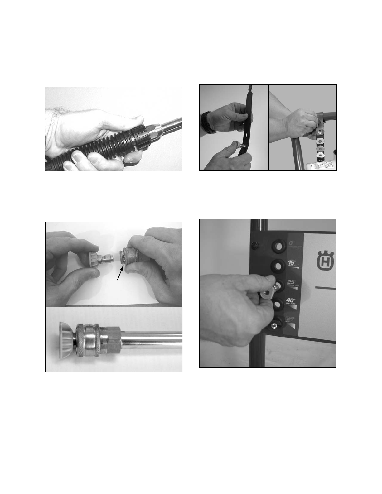
5. Attach the lance with nozzle to the gun (See
Figure 5).
6. Install quick connect tip by pulling back on collar
and pressing in tip. Release collar, make sure it
completely returns to its forward position and tip is
secure (See Figure 6).
PRE-OPERATION
Figure 5 - Attach lance to gun
Figure 6 - Quick Connect Tip
Pull collar back
For models 5525PW: Insert spray tips into the
rubber tip holder. Then attached the tip holder to
handle by wrapping around and inserting tail end
through hole to secure (See Figure 7).
For models 6027PW, 9032PW, and 1340PW: Insert
spray tips into rubber grommets on placard (See
Figure 8).
Figure 7 - Insert spray tips into the rubber tip
holder
Figure 8 - Insert spray tips into the placard
Page 11

10 — English
PRE-OPERATION
TRIGGER SAFETY LATCH
In the engaged position, the trigger safety latch
prevents the gun from being triggered accidentally.
Pull the latch up to engage it (See Figure 9). ALWAYS
engage the trigger safety latch when the unit is not in
use.
Figure 9 - Trigger lock
Trigger lock
(not engaged)
Trigger lock
(engaged)
Page 12

English — 11
OPERATION
1. Surface Preparation
ALWAYS engage the trigger safety latch when unit
is not in use. The following cleaning procedure will
help you organize your cleaning task and ensures
that you will achieve the best results in the shortest
amount of time. Remember to use the spraying /
cleaning techniques mentioned in the following
section.
Before starting a pressure washer cleaning job,
prepare the surface you intend to clean. Clear
furniture from the area and make sure that all
windows and doors are closed tightly. Also, protect
all plants and trees near the cleaning area with a
drop cloth. A covering ensures that your plants
won’t be sprayed by the detergents.
2. Start Up
ALWAYS use this start up procedure to ensure that
the unit is started safely and properly.
If water has frozen in the
pressure washer, thaw the
pressure washer in a warm room before starting. DO
NOT pour hot water on or into the pump; internal
parts will be damaged.
1. Check engine oil levels. Add oil as necessary.
NOTE: Some units are equipped with a low oil
sensor that shuts the engine off if the oil level falls
below a certain level. If the unit stops unexpectedly,
check both the oil and fuel levels. Check the oil
level each time you refuel the unit.
2. Check fuel level. Add unleaded gasoline (rated
86 octane or higher) as required.
DO NOT refuel a
hot engine.
Refueling a hot engine could cause a
fire. Use only fresh, clean unleaded
gasoline. Close the fuel shutoff valve
during refueling.
3. Attach a garden hose to the inlet connection for
garden hose and connect it to the water supply.
Use a hose with a minimum inside diameter of
5/8” (.016 m) and a length of 50 ft. (15 m) or
less.
Some local plumbing codes
require backflow prevention
when connecting to a fresh water supply. Install a
backflow preventer upstream from the pump if
necessary.
a. If inlet water pressure is over 100 psi, install a
regulating water valve at the garden hose
connection.
b. DO NOT exceed 100˚ F (38˚ C) inlet water
temperature.
NOTE: The inlet water supply must have a
minimum flow rate of 8 gpm (30 lpm) or 5 gpm
(191 lpm) on 5525PW.
4. Turn the water supply ON.
NEVER run the unit dry. Be sure
the water supply is completely
turned on before operating the unit.
5. Squeeze the gun until water sprays from the tip
indicating that all air is purged from the system.
Set the trigger safety latch.
6. On model 5525PW: Honda GC Engine:
Open the fuel shutoff valve by turning the knob
counterclockwise until it stops. Close the choke
(if engine is cold) by pulling the choke lever out.
The throttle is fixed.
On model 1340PW, 6027PW, and 9032PW:
Honda GX engine:
Open the fuel shutoff valve by pushing the lever
to the right. Close the choke (if the engine is
cold) by moving the choke lever fully to the left.
The throttle is fixed. Turn the On/Off switch to
the "ON" position.
7. Start the engine:
If the engine is cold, completely close the
engine choke.
If the engine is warm, leave the choke open or
just partially closed. Unlock the trigger safety
latch on the gun. Grasp the starter rope and
brace one foot on the chassis. While squeezing
the trigger on the gun, pull the starter rope
rapidly and firmly. Continue holding the rope as
it returns. Repeat these steps until the engine
starts. In cool weather, the choke may have to
be kept closed for 10 to 30 seconds to keep the
engine running. Otherwise, open the choke as
soon as the engine starts.
When pulling the starter rope,
make sure to keep your hand
and arm clear of the engine and cart components.
NEVER let the starter rope
return by itself. Doing so could
jam the recoil system.
3. Initial High Pressure Rinse
After the engine starts, trigger the gun 3 to 5 times
to get any trapped air out of the system. After the
spray becomes constant, you may need to adjust
the pressure (see pages 13 and 14 for cleaning
techniques).
NOTICE
!
WARNING
NOTICE
NOTICE
!
CAUTION
NOTICE
Page 13

12 — English
OPERATION
PRESSURE ADJUSTMENT
Models 9032PW and 1340PW have a pressure
adjustment knob located on the pump (see Figure
10). Turn the knob clockwise to increase the
pressure. Turn the knob counter clockwise to
decrease the pressure. DO NOT try and force the
knob to turn. The knob may already be at either
the lowest or highest setting.
If there is not a plastic adjustment knob located on
the pump (See Figure 10), then the pressure cannot
be adjusted. The only way to adjust the pressure is
to move closer or further away from the cleaning
surface and adjust the spray fan angle as shown in
the next section.
ADJUSTING THE SPRAY FAN ANGLE
Your unit has quick connect tips that have a range
of spray fan angles. Model 5525PW includes the
black detergent and yellow 15° quick connect tips
only.
The quick connect tips can be switched out from a
0° narrow high impact stream to a 65° wide fan
spray.
A narrow stream has high impact force on the
cleaning surface and results in maximum deep
cleaning in a concentrated area. However, this
narrow high impact spray can damage some
surfaces, so use it cautiously. Not recommended for
use on automotive paint, trim and vinyl siding.
A wide fan pattern will distribute the impact of the
water over a larger area resulting in excellent
cleaning action with reduced risk of surface
damage. Clean large surface areas quickly using a
wide fan pattern.
ANGLE TO THE CLEANING SURFACE
When spraying water against a surface, you can
generate maximum impact by striking the surface
head on. However, this type of impact can cause
dirt particles to embed in the surface and can
prevent the desired cleaning action.
Figure 10 - Camshaft pump pressure adjustment
Figure 11 - Installing Quick Connect Tip
Figure 12 - Narrow high impact stream
Figure 13 - Wide fan pattern
Pull collar back
Quick connect tip
The color of the tip shows what spray angle it is:
Red – 0° – Maximum Duty
Yellow – 15° – Heavy Duty
Green – 25° – General Duty
White – 40° – Light Duty
Black – 65° – Low Pressure Detergent
Page 14

English — 13
OPERATION
Spray water against a surface at a 45 degree angle
to achieve the most beneficial impact force and to
efficiently remove debris.
DISTANCE FROM CLEANING SURFACE
The distance between the spray nozzle and the
cleaning surface is another factor that affects the
impact force of the water. The impact force of the
water increases as the nozzle is moved closer to the
surface.
HOW TO AVOID DAMAGING SURFACES
Damage to cleaning surfaces occurs because the
impact force of the water exceeds the durability of
the surface. You can vary the impact force by
controlling the spray tip angle to the cleaning
surface and the distance from the cleaning surface
and by changing the spray tip. NEVER use a narrow
high impact stream on a surface that is susceptible
to damage. Avoid spraying windows with a narrow
high impact stream. Doing so may break the
window. The most sure way to avoid damaging
surfaces is to follow these steps:
1. Before triggering the gun, make sure the quick
connect tip you are using is appropriate for the
application.
2. Place the spray tip approximately 4-5 feet (1,221,52 m) away from the cleaning surface. Then
hold the lance and spray tip at a 45 degree
angle to the cleaning surface. Trigger the gun.
Figure 14 - Optimum angle to cleaning surface
The color of the tip shows what spray angle it is:
Red – 0° – Maximum Duty
Yellow – 15° – Heavy Duty
Green – 25° – General Duty
White – 40° – Light Duty
Black – 65° – Low Pressure Detergent
3. Vary the fan pattern spray angle and the
distance to the cleaning surface until optimum
cleaning efficiency is achieved without
damaging the surface.
4. Detergent Application
NOTE: Use only detergents formulated for pressure
washers.
NOTE: Test detergent in an inconspicuous area
before use.
NEVER replace quick connect tip
when gun is triggered.
DETERGENTS
The use of detergents can dramatically reduce
cleaning time and assist in the removal of difficult
stains. Many detergents are customized for pressure
washer use on specific cleaning tasks. Pressure
washer detergents are as thick as water. Using
thicker detergents – like dish soap – will clog the
chemical injection system and prevent the
application of the detergent.
Once applied to a cleaning surface, detergents take
time to break down dirt and grime. Detergents
work best when applied at low pressure.
You can effectively clean surfaces by combining the
chemical action of detergents with high pressure
rinses. On vertical surfaces, apply the detergent
starting at the bottom and work your way upward.
This method prevents the detergent from sliding
down and causing streaks. Begin high pressure
rinsing at the bottom and work your way upward.
On particularly tough stains, use a brush in
combination with detergents and high pressure
rinsing.
1. Follow manufacturer’s label directions for mixing
correct concentrations of soap/detergents. The
soap detergent to water ratio through the pump
is approximately 10% (1 to 10).
2. Insert the filter end of the clear plastic detergent
tube into the detergent container.
3. Use the BLACK 65° quick connect spray tip (all
models) (See Figure 15).
Figure 15 - Quick Connect Tip
!
WARNING
Page 15

14 — English
OPERATION
GENERAL CLEANING TIPS
1. Apply the detergent so that it thoroughly covers
the cleaning surface. Apply the detergent from
bottom to top to prevent the detergent from
sliding down and streaking. Wait a couple of
minutes for the detergent to break down the
dirt and grime. Use a brush to lightly scrub
heavily soiled areas. NEVER allow the detergent
to dry on the cleaning surface.
2. Replace black 65° quick connect tip with another
color tip.
NEVER replace quick connect tip
when gun is triggered.
3. After using detergents, flush the suction system
by placing the detergent suction tube into a
bucket of clean water.
5. Cleaning Power
The easiest way to regulate the cleaning power of
your pressure washer is by changing the distance
from the surface you are cleaning. Begin spraying
with a wide fan pattern while standing several feet
from the surface. Slowly move closer to the object
you are cleaning, adjusting the spray pattern as
necessary, until you find the most effective cleaning
technique.
NOTE: Some units also may have a pressure
adjustment knob on the pump that can adjust the
pressure (models 9032PW and 1340PW).
6. Final Rinse
The final rinse should start at the bottom and work
upward. Make sure that you thoroughly rinse the
surface and that you remove all detergent.
7. Shutdown
1. Be sure all detergent is flushed from system.
2. Turn the engine OFF.
3 Turn the water supply OFF.
4. After the engine and water supply are turned
OFF, trigger the gun to depressurize the system.
NEVER turn the water supply
off before turning the
engine/motor off. Serious damage could occur to the
pump and/or engine/motor.
NEVER disconnect the high
pressure discharge hose from
the machine while the system is pressurized. To
depressurize, turn engine/motor off, turn water
supply off and squeeze gun trigger 2-3 times.
5. After each use, when engine has cooled, wipe all
surfaces of the pressure washer with a clean,
damp cloth.
• DO NOT store the pressure washer outdoors.
• DO NOT store the pressure washer where it
might freeze unless it has been properly
winterized.
8. Storage
LONG TERM STORAGE INSTRUCTIONS (MORE
THAN 30 DAYS IN STORAGE)
1. Remove fuel from the tank and run the pressure
washer in a normal operating mode until the
engine stops from a lack of fuel. Normal
operating mode means actually spraying water
from the gun while the engine is running.
Alternate method – Add fuel stabilizer to gas in
the tank and run in normal operating mode for
at least five minutes.
2. Stop the engine, turn off the water supply, and
trigger the gun to release pressure in the highpressure hose.
PRESSURE RELIEF
PROCEDURE
To reduce the risk of bodily injury or property
damage, ALWAYS follow this procedure
whenever spraying is stopped, when work is
completed, and before checking or repairing
any part of the system.
1. Engage the trigger safety latch.
2. Turn the unit off.
3. Shut off the water supply.
4. Disengage the trigger safety latch and
trigger the gun to relieve pressure.
5. Re-engage the trigger safety latch.
6. Before overnight storage, long term
storage, or transporting unit, disconnect
the water supply and turn off the fuel
supply valve.
!
WARNING
NOTICE
!
CAUTION
Page 16

English — 15
OPERATION
3. Disconnect the water supply and high pressure hose
from the pump.
4. Allow the engine to cool.
5. Disconnect the spark plug wire and remove the
spark plug.
6. Pour 1/2 oz. of engine oil into the spark plug hole.
NEVER pull the
starter rope on the
engine when the spark plug is removed
unless the spark plug hole is covered.
Fuel vapor from the hole can ignite by a
spark.
7. Place a rag over the spark plug hole and slowly pull
the starter rope several times to distribute the oil.
8. Disconnect the high pressure hose from the pump.
9. Insert a 12” to 14” piece of garden hose into the
pump inlet.
10. Place a funnel in the other end of the garden hose.
Read the manufacturer’s
instructions for safe handling
and disposal of RV antifreeze.
11. Pour approximately 6 oz. of RV antifreeze into
the funnel.
12. Pull the starter rope several times until the RV
antifreeze comes out of the pump outlet.
13. Disconnect the high pressure hose from the gun
and drain the hose. Hold the gun and lance in a
vertical position and squeeze the trigger to
drain the water.
Never store the pressure washer
with gasoline in the tank inside
a building where fumes may reach an open flame or
spark. Allow the engine to cool before storing in
any enclosure.
NOTE: To winterize unit, please follow the same
intructions for Storage.
TIPS FOR EXTENDING THE LIFE OF YOUR PRESSURE
WASHER
• NEVER operate the unit without water.
• Your pressure washer is not meant to pump hot
water. NEVER connect your pressure washer to a
hot water supply as it will significantly reduce
the life of the pump.
• Running the unit for more than two minutes
without spraying water causes heat to build up
in the pump. Running the unit without spraying
water can damage pump components.
• Release the trigger prior to switching the lance
between high and low pressure. Failure to do so
may reduce the life of the o-rings in the lance.
!
WARNING
NOTICE
!
CAUTION
Page 17

16 — English
MAINTENANCE
Observe regular maintenance intervals to ensure
maximum performance and life from the pressure
washer. Refer to the schedule for recommended
maintenance. If you operate the pressure washer in
dusty conditions, perform maintenance checks more
often.
ENGINE OIL CHANGING INSTRUCTIONS
Before tipping the engine or
equipment to drain oil, drain fuel
from the fuel tank.
NOTE: Change oil while the engine is cool.
1. Disconnect the spark plug wire from the spark
plug.
2. Locate and remove the engine oil drain plug (see
Figure 18).
3. Drain old oil.
4. Replace the drain plug and set the unit upright.
5. Refill the unit with new oil of a recommended
type and quantity. Fill the unit to the proper
level shown on the dipstick (if provided).
Otherwise, fill the unit to the top of the oil filler
neck.
Figure 16
Model 5525PW - Engine Oil Drain Plug
Models 1340PW, 6027PW, and 9032PW - Engine Oil
Drain Plug
Engine Oil Type SAE 10W-30
SAE 30W (Above 60 °F/15.7° C)
Engine Oil Capacity
5525PW - Honda GCV160 - 18.6 fl. oz. (0.550 L)
6027PW - Honda GX160 - 20 fl. oz. (0.591 L)
9032PW - Honda GX270 - 37 fl. oz. (1.090 L)
1340PW - Honda GX390 - 37 fl. oz. (1.090 L)
!
CAUTION
Page 18

English — 17
MAINTENANCE
CHECKING PUMP OIL AND PUMP OIL CHANGING
Checking oil level: Most pumps have either a sight
glass or a dipstick (or both) to check the pump oil
level. The correct oil level is at the center of the
sight glass (center of red dot). The sight glass is
usually located on the back side of the pump [See
Figure 19 (B)].
For model 5525PW: Pump is factory sealed.
Changing or refilling the oil in the pump requires
removal of the pump from the engine and should
not be required unless oil has leaked out due to
worn or damaged oil seals in the pump. If oil has
leaked out of the pump, bring the pressure washer
to a certified service center for repair.
For models 6027PW, 9032PW, and 1340PW: These units
all have a sight glass to check the oil level and have a
drain plug to remove the old oil when changing. To
add oil remove vent cap from top of pump [See
Figure 19 (A)].
Figure 17 - Pump Oil Filler Vent Cap (A), Sight Glass
(B), and Drain Plug (C) Locations
(A)
(B)
(C)
Changing oil: Remove the oil drain plug located at
the backside of the pump [See Figure 19 (C)]. Drain
old oil. Replace drain plug. Refill pump with the
correct type and amount of oil (see below for oil
types and amounts). Check oil level. Upon starting
the pressure washer check for any pump oil leaks.
Pump Oil Type
5525PW - Lavor Pump - Special. See pump
parts list.
6027PW, 9032PW, 1340PW - CAT Pumps Special CAT pump oil. Use 531 30 74-83.
DO NOT use any oil in pumps other than the
manufacturer's oil.
Page 19

18 — English
MAINTENANCE SCHEDULE
Each use
After first 5 hours of operation
After first 50 hours of operation
Every 25 hours of operation
Every 50 hours of operation
Each 100 hours of operation or every 3
months
Every 500 hours of operation (5 months)
• Check water inlet screen and filter.
• Check engine and pump oil levels. Fill as necessary. Cannot check
pump oil on the 5525PW.
• Check gasoline level. Fill as necessary.
• Change engine break-in oil. Use SAE30 or 10W-30 detergent
oil if below 60° F (15.7° C).
• Change pump oil. Cannot check or change pump oil on the
5525PW.
• Change engine oil if operating under heavy load or high
ambient temperature.
• Remove and clean foam pre-cleaner or foam air filter (if
applicable). Wash with water and mild detergent. Dry
thoroughly. Rub with oil and squeeze to distribute oil.
• Change engine oil.
• Replace spark plug.
• Clean or replace paper air cleaner cartridge. Tap gently to
remove dirt.
• Change engine oil.
• Change pump oil. Cannot check or change pump oil on the
5525PW.
Maintenance Schedule Action needed
NOTE: This is a general maintenance schedule. Refer to the Engine operation manual for specific information
on your engine.
Page 20

English — 19
TECHNICAL AND CONSUMER INFORMATION
Engine Oil Type SAE 10W-30
SAE 30W (Above 60 °F/15.7° C)
Engine Oil Capacity
5525PW - Honda GCV160 - 18.6 fl. oz. (0.550 L)
6027PW - Honda GX160 - 20 fl. oz. (0.591 L)
9032PW - Honda GX270 - 37 fl. oz. (1.090 L)
1340PW - Honda GX390 - 37 fl. oz. (1.090 L)
Engine Fuel Capacity
5525PW - Honda GCV160 - 1.2 US quarts (1.09 L)
6027PW - Honda GX160 - 3.3 US quarts (3.1 L)
9032PW - Honda GX270 - 5.6 US quarts (5.3 L)
1340PW - Honda GX390 - 6.4 US quarts (6.1 L)
Pump Oil Type
5525PW - Lavor Pump - Special. See pump parts
list.
6027PW, 9032PW, 1340PW - CAT Pumps -Special
CAT pump oil. See pump parts list.
DO NOT use any oil in pumps other than the
manufacturer's oil.
Pressure Washers
Pump Oil Capacity
5525PW - AR RM Pump - 3.5 fl.oz. (0.103 L)
6027PW - CAT 3DNX Pump -8.5 fl.oz. (0.251 L)
9032PW - CAT 66DX Pump -10.15 fl.oz. (0.532 L)
1340PW - CAT 66DX Pump -18 fl.oz. (0.532 L)
Pump Detergent Suction
Water to detergent 8 to 1
ratio (5525PW) (12% detergent)
Water to detergent 10 to 1
ratio (6027PW, 10% detergent)
9032PW, 1340PW)
Water Supply Requirements
Minimum inlet pressure 20 psi
Maximum inlet pressure 100 psi
Maximum inlet
temperature 100° F / 38° C
Minimum inlet flow rate
5525PW 5 gpm (18.9 lpm)
6027PW, 9032PW, 2 times the rated
1340PW flow of unit or
8 gpm (30.3 lpm)
Inlet garden hose size 5/8” ID (15.9 mm)
Maximum inlet garden
hose length 50 ft. (15,2 m)
Page 21

20 — English
TROUBLESHOOTING CHART
Troubleshooting Chart - Gasoline Powered Pressure Washers Only
Symptom Possible Cause(s) Corrective Action(s)
Engine will not start
or is hard to start
Engine misses or
lacks power
Low pressure and/or
pump runs rough
Water leakage from
under pump
manifold
Water in pump
crankcase (milky oil)
Frequent or
premature failure of
the pump water
seals
Strong surging at
the inlet and low
pressure
1. No gasoline in fuel tank or
carburetor
2. Low oil
3. Start/Stop switch in stop position
4. Water in gasoline or old fuel
5. Dirty air cleaner filter
6. Spark plug dirty, wrong gap or
wrong type
7. Spray gun closed
8. Other causes
1. Partially plugged air cleaner filter
2. Spark plug dirty, wrong gap or
wrong type
3. Bad Fuel
1. Worn or wrong size tip
2. Inlet filter on pump clogged
3. Worn water seals, abrasives in
water, or natural wear
4. Fouled or dirty inlet or discharge
valves
5. Restricted inlet
6. Worn inlet or discharge valves
7. Leaking high pressure hose
8. Pump drawing in air
9. Unloader valve seat faulty or worn
10. Inlet water temperature too high
Worn water seals
1. Humid air condensing inside
crankcase
2. Oil seals leaking
3. Water seals leaking
1. Scored damaged or worn plungers
2. Abrasive material in the fluid
3. Inlet water temperature too high
4. Overpressurizing pump
5. Excessive pressure due to partially
plugged or damaged tip
6. Pump running too long without
spraying
7. Pump running dry
Foreign particles in the inlet or
discharge valve or worn inlet and/or
discharge valves
1. Fill the tank with gasoline,open fuel
shut off valve. Check fuel line and
carburetor
2. Check oil level. Fill if necessary
3. Move switch to start position
4. Drain fuel tank and carburetor. Use new
fuel and dry spark plug
5. Remove and clean or replace
6. Clean, adjust the gap, or replace
7. Trigger spray gun
8. See engine owner’s manual
1. Remove and clean or replace
2. Clean, adjust the gap, or replace
3. Drain fuel and carburetor. Use new
fuel.
1. Replace with tip of proper size
2. Clean. Check more frequently
3. Check filter. Replace water seals. See
service center
4. Clean inlet and discharge valve
assemblies. Check filter
5. Check garden hose, may be collapsed or
kinked. Check inlet water flow
6. Replace worn valves
7. Replace high pressure hose
8. Ensure hoses and fittings are tight
9. Check and replace
10. Check water temperature; may not
exceed 100° F / 38° C
Install new water seals. See service center
1. Change oil as specified in maintenance
schedule
2. Install new oil seals. See service center
3. Install new water seals. See service
center
1. Install new plungers. See service center
2. Install proper filtration on pump inlet
plumbing
3. Check water temperature; may not
exceed 100° F / 38° C
4. DO NOT modify any factory set
adjustments
5. Clean or replace tip
6. NEVER run pump more than 2 minutes
without spraying
7. DO NOT run pump without water
Clean or replace valves. See service center
Page 22

English — 21
TROUBLESHOOTING CHART
Symptom Possible Cause(s) Corrective Action(s)
Oil leakage
between the engine
and the pump
Fluctuating pressure
Pressure drops after
period of normal
use
Pump noisy / pump
runs rough
Pressure washer will
not spray detergent
Worn oil seals and/or o-ring
1. Low engine oil
2. Pump valve worn, dirty or stuck
3. Pump drawing in air
4. Tip clogged
1. Worn pump water seals
2. Spray tip worn
3. Pump valve worn, dirty or stuck
4. Unloader valve seat worn or dirty
5. If using high pressure soap lance
accessory; nozzle in low PSI position
1. Pump drawing in air/low water
supply
2. Valves dirty or worn
3. Worn bearings
4. Water too hot
1. Not using quick connect detergent
tip
2. Clog, kink, or hole in detergent
suction hose
3. High pressure hose length too long
4. Detergent injector clogged
Replace oil seals and/or o-ring. See service
center
1. Add oil.
2. Check and replace
3. Ensure hoses and fittings are tight.
Purge air from garden hose
4. Check or replace
1. Check and replace
2. Check and replace
3. Check, clean or replace
4. Check, clean or replace
5. Pull back nozzle to high pressure
position
1. Ensure fittings are tight. Increase water
pressure
2. Check, clean or replace
3. Check and replace
4. Reduce temperature below 100°F / 38°C
1. Use black quick connect detergent tip
2. If clean, unkink or replace hose
3. Use only hose length provided with
initial purchase of pressure washer.
Detergent suction will not function if
more than once section of hose is
attached to unit
4. Remove 1” (2,54 cm) tapered detergent
barb from pump. Clean the barb, and
make sure that ball and spring are
properly aligned with tapered portion
of the spring facing the ball. The ball
should be on top of the spring
Page 23

SERVICE RECORD
22 — English
Date Maintenance performed Replacement components required
Page 24

English — 23
5525PW
531 30 75-38 Detergent Tube (not shown)
* Tips sold separately; contact your dealer to
purchase
505 27 16-01
531 30 74-97
531 30 74-84
531 30 75-35
531 30 74-69
531 30 74-96
505 19 45-24
531 30 75-41 (x2)
531 30 75-43 (x4)
531 30 75-28
531 30 75-31
531 30 75-30
531 30 75-32
531 30 74-61 (x2)
531 30 75-39 (x1)
531 30 81-11 (x2)
531 30 81-12
531 30 74-72
531 30 74-77 (Soap)
531 30 74-78 (0°) *
531 30 74-79 (15°)
531 30 74-80 (25°) *
531 30 74-81 (40°) *
Page 25

24 — English
6027PW
505 19 45-40
505 27 16-02
505 19 45-42
531 30 75-44
531 30 74-87
531 30 74-68
531 30 74-86
531 30 75-39 (x1)
531 30 75-45 (x2)
531 30 75-47
531 30 74-91
531 30 74-95
531 30 55-49 (x2)
531 30 74-66 (x5)
505 19 45-39
531 30 74-60 Detergent Tube (not shown)
531 30 74-82
531 30 74-84
531 30 74-72
531 30 74-77 (Soap)
531 30 74-78 (0°)
531 30 74-79 (15°)
531 30 74-80 (25°)
531 30 74-81 (40°)
531 30 75-40 (x2)
531 30 75-50 (x6)
Page 26

English — 25
9032PW & 1340PW
505 19 45-41
505 19 45-42
531 30 74-87
531 30 74-86
531 30 74-68
531 30 75-44
531 30 74-77 (Soap)
505 19 45-43 (0°)
505 19 45-44 (15°)
505 19 45-45 (25°)
505 19 45-46 (40°)
505 27 16-03 (9032PW)
505 27 16-04 (1340PW)
531 30 74-71 Detergent Tube (not shown)
531 30 74-82
531 30 74-84
531 30 74-72
531 30 75-39 (x1)
531 30 75-45 (x2)
531 30 75-47
531 30 74-91
531 30 74-95
531 30 55-49 (x2)
531 30 74-66 (x5)
505 19 45-39
531 30 75-40 (x2)
531 30 75-50 (x6)
Page 27

26 — English
Pump for 5525PW
505 27 18-01 Pump Assembly Complete
505 19 45-22
505 19 45-23
Key: P/O = Part Of KIt
505 19 45-21
505 19 45-20
P/O 505 19 45-02
505 19 45-18
P/O 505 19 45-09
505 19 45-17
505 19 45-16
505 19 45-15
505 19 45-14
505 19 45-13
505 19 45-12
505 19 45-11
505 19 45-10
P/O 505 19 45-09
P/O 505 19 45-09
P/O 505 19 45-06
P/O 505 19 45-09
505 19 45-08
505 19 45-07
P/O 505 19 45-06
P/O 505 19 45-02
505 19 45-03
505 19 45-05
505 19 45-04
505 19 45-19
505 19 45-01
Page 28

English — 27
Pump for 6027PW
505 19 45-25
505 19 45-38
505 19 45-27
505 19 45-28
505 19 45-26
530 30 75-85
P/O 505 19 45-35
531 30 75-90
530 30 75-84
530 30 75-13
531 30 75-88
530 30 75-82
530 30 75-81
530 30 75-80
530 30 75-79
530 30 75-78
530 30 75-77
P/O 505 19 45-35
505 27 18-02 Pump Assembly Complete
531 30 75-16
505 19 45-29
505 19 45-31
531 30 75-71
505 19 45-32
531 30 75-73
531 30 75-74
531 30 75-75
531 30 75-76
505 19 45-34
505 19 45-28
505 19 45-33
505 19 45-37
531 30 74-83 Pump Oil (not shown)
Key: P/O = Part Of KIt
531 30 75-87
530 30 75-86
505 19 45-36
531 30 75-53
Page 29

28 — English
Pump for 9032PW
531 30 74-83 Pump Oil (not shown)
Key: P/O = Part Of KIt
505 19 45-27
505 19 45-38
P/O 505 19 45-35
505 19 45-49
505 19 45-48 (x3)
505 19 45-54
505 19 45-51
505 19 45-29
505 19 45-28
505 19 45-55
P/O 505 19 45-35
505 19 45-50
505 19 45-59
505 19 45-34
505 19 45-31
505 19 45-57
505 19 45-56
505 19 45-32
505 19 45-33
505 19 45-58
531 30 75-16
505 19 45-53
P/O 505 19 45-60
P/O 505 19 45-60
505 19 45-52
530 30 75-77
505 19 45-47
530 30 75-79
505 27 18-03 Pump Assembly Complete
505 19 45-61
Page 30

English — 29
505 19 45-63
505 19 45-68
505 19 45-62
505 19 45-64
P/O 505 19 45-67
505 19 45-65
P/O 505 19 45-67
531 30 74-83 Pump Oil (not shown)
Key: P/O = Part Of KIt
505 19 45-66
Pump for 1340PW
505 19 45-69
531 30 75-25
531 30 75-26
531 30 75-24
505 19 45-79
531 30 75-20
531 30 75-21
531 30 75-22
505 19 45-68
531 30 75-19
505 19 45-79
505 19 45-62
531 30 75-27
505 19 45-70
505 19 45-71
505 19 45-72
505 19 45-73
505 19 45-74
505 19 45-75
P/O
531 30 75-92
P/O 505 19 45-78
505 19 45-76
505 19 45-77
P/O 505 19 45-78
P/O 505 19 45-78
505 19 45-80
P/O 531 30 75-92
P/O 531 30 75-92
505 27 18-04 Pump Assembly Complete
531 30 75-23
P/O 531 30 75-62
P/O 531 30 75-62
P/O 531 30 75-60
P/O 531 30 75-60
P/O 531 30 75-64
P/O 531 30 75-64
P/O 531 30 75-65
P/O 531 30 75-65
531 30 75-22
Page 31

30 — English
NOTES
Page 32

English — 31
Product Registration Notice!
Eective May 1, 2007
FAST! EASY! SIMPLE!
Register your Husqvarna product on-line quickly and easily. Paper registration forms will not be accepted.
There will be a grace period for products built prior to January 1, 2007. All Husqvarna products can be
registered online regardless of their model year. Register products online at www.usa.husqvarna.com ,
Page 33

32 — English
 Loading...