

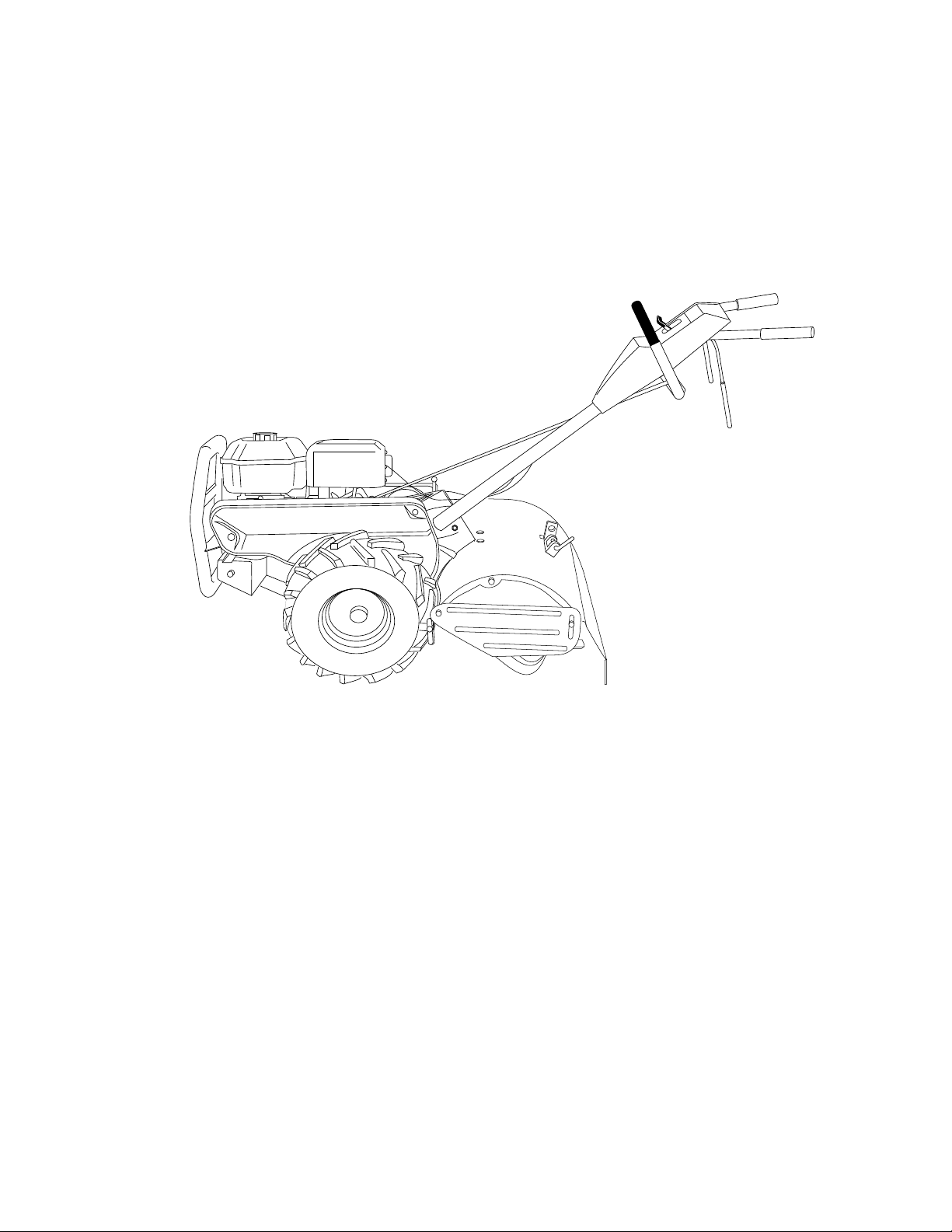
600CRT
Owner’s Manual
SAFETY RULES
Safe Operation Practices for Walk-Behind Powered Rotary Tillers
TRAINING
• Read the Owner’s Manual carefully. Be thoroughly
familiar with the controls and the proper use of the
equipment. Know how to stop the unit and disengage
the controls quickly.
• Never allow children to operate the equipment. Never
allow adults to operate the equipment without proper
instruction.
• Keep the area of operation clear of all persons, particularly small children, and pets.
PREPARATION
• Thoroughly inspect the area where the equipment is to
be used and remove all foreign objects.
• Disengage all clutches and shift into neutral before
starting the engine (motor).
• Do not operate the equipment without wearing adequate outer garments. Wear footwear that will improve footing on slippery surfaces.
• Handle fuel with care; it is highly flammable.
• Use an approved fuel container.
• Never add fuel to a running engine or hot engine.
• Fill fuel tank outdoors with extreme care. Never fill fuel
tank indoors.
• Replace gasoline cap securely and clean up spilled
fuel before restarting.
• Use extension cords and receptacles as specified by
the manufacturer for all units with electric drive motors
or electric starting motors.
• Never attempt to make any adjustments while the
engine (motor) is running (except where specifically
recommended by manufacturer).
OPERATION
• Do not put hands or feet near or under rotating parts.
• Exercise extreme caution when operating on or crossing gravel drives, walks, or roads. Stay alert for hidden
hazards or traffic. Do not carry passengers.
• After striking a foreign object, stop the engine (motor),
remove the wire from the spark plug, thoroughly inspect the tiller for any damage, and repair the damage
before restarting and operating the tiller.
• Exercise caution to avoid slipping or falling.
• If the unit should start to vibrate abnormally, stop the
engine (motor) and check immediately for the cause.
Vibration is generally a warning of trouble.
• Stop the engine (motor) when leaving the operating
position.
• Take all possible precautions when leaving the machine unattended. Disengage the tines, shift into
neutral, and stop the engine.
• Before cleaning, repairing, or inspecting, shut off the
engine and make certain all moving parts have stopped.
Disconnect the spark plug wire, and keep the wire
away from the plug to prevent accidental starting.
Disconnect the cord on electric motors.
• Do not run the engine indoors; exhaust fumes are
dangerous.
• Never operate the tiller without proper guards, plates,
or other safety protective devices in place.
• Keep children and pets away.
• Do not overload the machine capacity by attempting to
till too deep at too fast a rate.
• Never operate the machine at high speeds on slippery
surfaces. Look behind and use care when backing.
• Never allow bystanders near the unit.
• Use only attachments and accessories approved by
the manufacturer of the tiller.
• Never operate the tiller without good visibility or light.
• Be careful when tilling in hard ground. The tines may
catch in the ground and propel the tiller forward. If this
occurs, let go of the handlebars and do not restrain the
machine.
MAINTENANCE AND STORAGE
• Keep machine, attachments, and accessories in safe
working condition.
• Check shear pins, engine mounting bolts, and other
bolts at frequent intervals for proper tightness to be
sure the equipment is in safe working condition.
• Never store the machine with fuel in the fuel tank inside
a building where ignition sources are present, such as
hot water and space heaters, clothes dryers, and the
like. Allow the engine to cool before storing in any
enclosure.
• Always refer to the operator’s guide instructions for
important details if the tiller is to be stored for an
extended period.
- IMPORTANT -
CAUTIONS, IMPORTANTS, AND NOTES ARE A MEANS
OF ATTRACTING ATTENTION TO IMPORTANT OR
CRITICAL INFORMATION IN THIS MANUAL.
IMPORTANT: USED TO ALERT YOU THAT THERE IS A
POSSIBILITY OF DAMAGING THIS EQUIPMENT.
NOTE: Gives essential information that will aid you to
better understand, incorporate, or execute a particular set
of instructions.
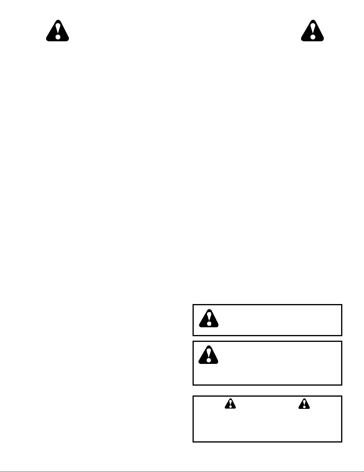
Look for this symbol to point out important safety precautions. It means
CAUTION!!! BECOME ALERT!!! YOUR
SAFETY IS INVOLVED.
CAUTION: Always disconnect spark
plug wire and place wire where it cannot contact spark plug in order to prevent accidental starting when setting
up, transporting, adjusting or making
repairs.
WARNING
The engine exhaust from this product contains chemicals known to the State of California to cause cancer, birth defects, or other
reproductive harm.
2

CONGRATULATIONS on your purchase of a new tiller. It
PRODUCT SPECIFICATIONS
has been designed, engineered and manufactured to give
you the best possible dependability and performance.
Should you experience any problems you cannot easily
remedy, please contact your nearest authorized service
center. We have competent, well-trained technicians and
HORSEPOWER: 6.0 HP
DISPLACEMENT: 13.53 cu. in. (221.8cc)
the proper tools to service or repair this unit.
Please read and retain this manual. The instructions will
enable you to assemble and maintain your tiller properly.
GASOLINE CAPACITY: 4 Quarts
Unleaded Regular
Always observe the “SAFETY RULES”.
MODEL
NUMBER 600CRT
SERIAL
NUMBER________________________________
OIL(API-SF/SG/SH) : SAE 30 (Above 32°F/0°C)
(CAPACITY: 20 oz./0.6L) SAE 5W-30 (Below 32°F/0°C)
SPARK PLUG : Champion
(GAP: .030"/0.76mm) J8C
DATE OF PURCHASE _____________________
THE MODEL AND SERIAL NUMBERS WILL BE
FOUND ON THE MODEL PLATE ATTACHED TO
THE TOP OF THE TRANSMISSION.
YOU SHOULD RECORD BOTH SERIAL NUMBER
AND DATE OF PURCHASE AND KEEP IN A SAFE
PLACE FOR FUTURE REFERENCE.
CUSTOMER RESPONSIBILITIES
• Read and observe the safety rules.
• Follow a regular schedule in maintaining, caring for and
using your tiller.
• Follow instructions under “Customer Responsibilities”
and “Storage” sections of this Owner’s Manual.
IMPORTANT: THIS UNIT IS EQUIPPED WITH AN INTERNAL COMBUSTION ENGINE AND SHOULD NOT BE USED ON OR
NEAR ANY UNIMPROVED FOREST-COVERED, BRUSH-COVERED OR GRASS COVERED LAND UNLESS THE ENGINE'S
EXHAUST SYSTEM IS EQUIPPED WITH A SPARK ARRESTER MEETING APPLICABLE LOCAL LAWS (IF ANY). IF A
SPARK ARRESTER IS USED, IT SHOULD BE MAINTAINED IN EFFECTIVE WORKING ORDER BY THE OPERATOR.
IN THE STATE OF CALIFORNIA, A SPARK ARRESTER IS REQUIRED BY LAW (SECTION 4442 OF THE CALIFORNIA
PUBLIC RESOURCES CODE). OTHER STATES MAY HAVE SIMILAR LAWS. FEDERAL LAWS APPLY ON FEDERAL
LANDS. SEE YOUR AUTHORIZED SERVICE CENTER/DEPARTMENT FOR SPARK ARRESTER.
3

TABLE OF CONTENTS
SAFETY RULES............................................................2
CUSTOMER RESPONSIBILITIES ......................3,12-14
PRODUCT SPECIFICATIONS ...................................... 3
ASSEMBLY ................................................................5-7
OPERATION.............................................................8-11
MAINTENANCE SCHEDULE......................................12
SERVICE & ADJUSTMENTS.................................14-17
STORAGE ...................................................................18
TROUBLESHOOTING................................................. 19
REPAIR PARTS-TILLER........................................20-26
WARRANTY ................................................................ 27
4
ASSEMBLY
Your new tiller has been assembled at the factory with exception of those parts left unassembled for shipping purposes. To
ensure safe and proper operation of your tiller all parts and hardware you assemble must be tightened securely. Use the
correct tools as necessary to insure proper tightness.
TOOLS REQUIRED FOR ASSEMBLY
A socket wrench set will make assembly easier. Standard
wrench sizes are listed.
(1) Utility knife
(1) Tire pressure gauge
(1) Pair of pliers
(1) 9/16" wrench
OPERATOR’S POSITION (See Fig. 1)
When right or left hand is mentioned in this manual, it
means when you are in the operating position (standing
behind tiller handles).
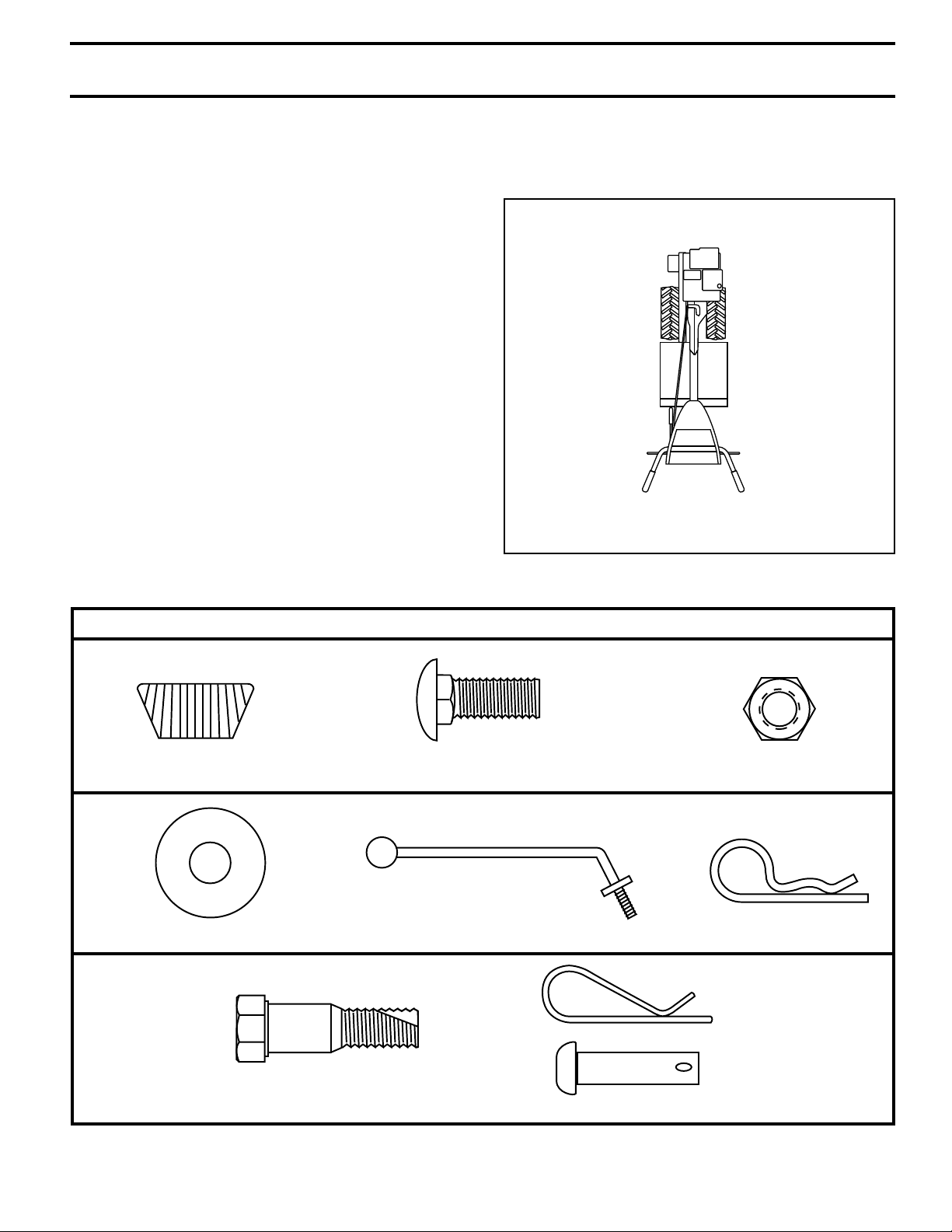
CONTENTS OF HARDWARE PACK
LEFT
FRONT
RIGHT
OPERATOR’S
POSITION
FIG. 1
(2) Handle Locks
(1) Flat Washer 13/32 x 1 x 11 Gauge
(1) Pivot Bolt
3/8-16 UNC Grade 5
(1) Carriage Bolt
3/8-16 UNC x 1 Grade 5
(1) Handle Lock Lever
Extra Shear Pins & Clips
5
(1) Center Locknut
3/8-16 UNC
(1) Hairpin Clip
ASSEMBLY
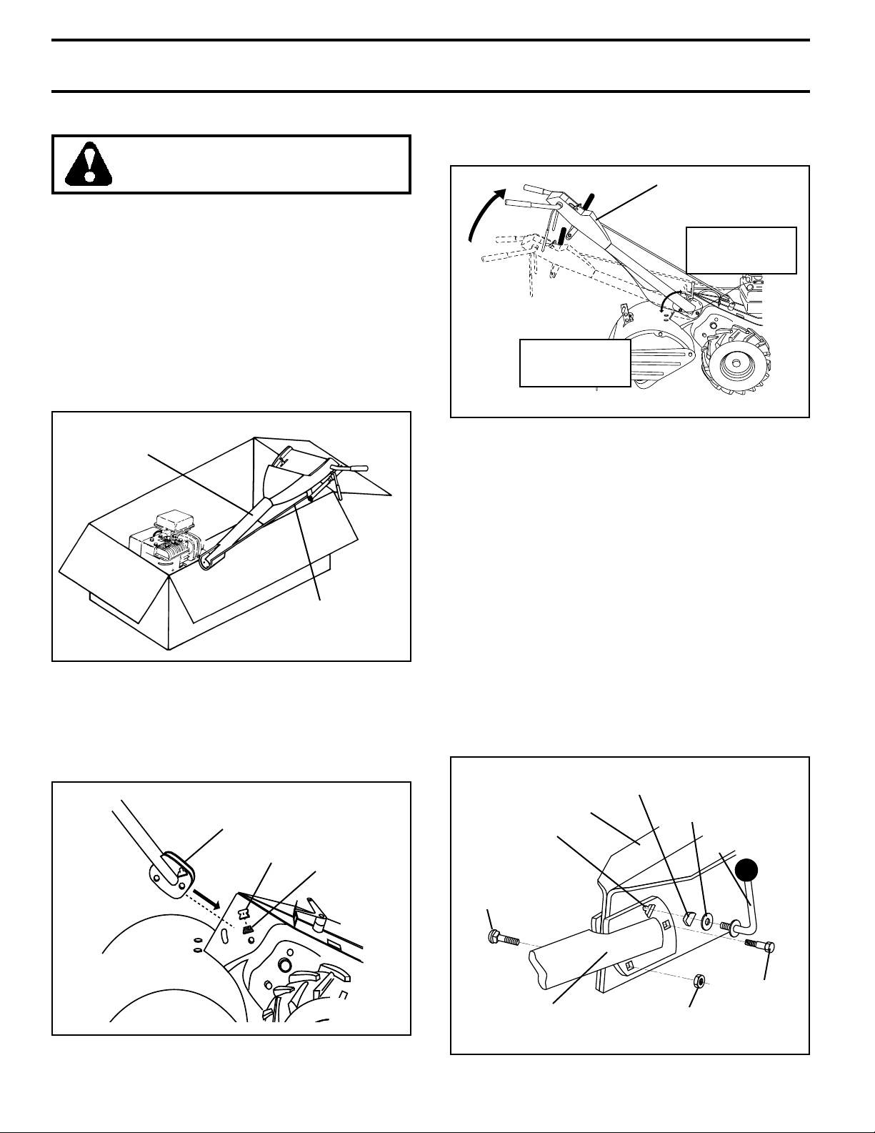
UNPACKING CARTON (See Fig. 2)
CAUTION: Be careful of exposed
staples when handling or disposing of
cartoning material.
IMPORTANT: WHEN UNPACKING AND ASSEMBLING
TILLER, BE CAREFUL NOT TO STRETCH OR KINK
CABLES.
• While holding handle assembly, cut cable ties securing
handle assembly to top frame and depth stake. Let
handle assembly rest on tiller.
• Remove top frame of carton.
• Slowly ease handle assembly up and place on top of
carton.
• Cut down right hand front and right hand rear corners
of carton, lay side carton wall down.
• Remove packing material from handle assembly.
HANDLE
ASSEMBLY
SHIFT ROD
FIG. 2
INSTALL HANDLE (See Figs. 3, 4, and 5)
• Insert one handle lock (with teeth facing outward) in
gearcase notch. (Apply grease on smooth side of
handle lock to aid in keeping lock in place until handle
assembly is lowered into position.)
VIEWED FROM R.H. SIDE OF TILLER
HANDLE ASSEMBLY
GEARCASE
NOTCH
HANDLE
LOCK
• Grasp handle assembly. Hold in “up” position. Be sure
handle lock remains in gearcase notch. Slide handle
assembly into position.
HANDLE ASSEMBLY
"UP" POSITION
TIGHTEN HANDLE
LOCK LEVER TO
HOLD
LOOSEN HANDLE
LOCK LEVER TO
MOVE
FIG. 4
• Rotate handle assembly down. Insert rear carriage bolt
first, with bolt head on L.H. side of tiller and loosely
assemble locknut (See Fig. 5).
• Insert pivot bolt in front part of plate and tighten.
• Cut down remaining corners of carton and lay panels
flat.
• Lower the handle assembly. Tighten nut on carriage
bolt so handle moves with some resistance. This will
allow for easier adjustment.
• Place flat washer on threaded end of handle lock lever.
• Insert handle lock lever through handle base and
gearcase. Screw in handle lock lever just enough to
hold lever in place.
• Insert second handle lock (with teeth inward) in the slot
of the handle base (just inside of washer).
• With handle assembly in lowest position, securely
tighten handle lock lever by rotating clockwise. Leaving handle assembly in lowest position will make it
easier to remove tiller from carton.
HANDLE
LOCK
GEARCASE
SLOT
CARRIAGE
BOLT
FLAT
WASHER
HANDLE LOCK
LEVER
FIG. 3
PIVOT BOLT
HANDLE
BASE
LOCKNUT
FIG. 5
6
ASSEMBLY
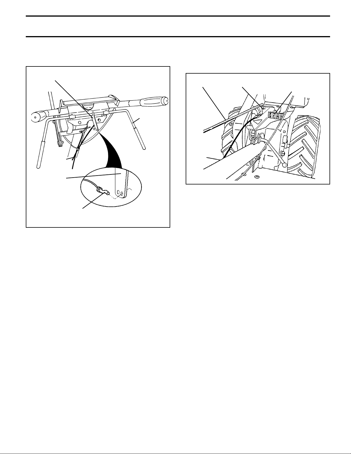
ATTACH CLUTCH CABLE (See Fig. 6)
• Hook end of clutch cable through hole in control bar
bracket.
CONTROL BAR
BRACKET
CONTROL
BAR
CLUTCH
CABLE
CONTROL BAR
BRACKET
END OF CLUTCH
CABLE
FIG. 6
CONNECT SHIFT ROD (See Fig. 7)
• Insert end of shift rod into hole of shift lever indicator.
• Insert hairpin clip through hole of shift rod to secure.
SHIFT
ROD
HAIRPIN
CLIP
SHIFT
LEVER
INDICATOR
FIG. 7
REMOVE TILLER FROM CRATE
• Make sure shift lever indicator is in “N” position (See
Fig. 7)
• Tilt tiller forward by lifting handle. Separate cardboard
cover from leveling shield.
• Rotate tiller handle to the right and pull tiller out of
carton.
CHECK TIRE PRESSURE
The tires on your unit were overinflated at the factory for
shipping purposes. Correct and equal tire pressure is
important for best tilling performance.
• Reduce tire pressure to 20 PSI (1.4 kg/cm2).
HANDLE HEIGHT
• Handle height may be adjusted to better suit operator.
(See “TO ADJUST HANDLE HEIGHT” in the Service
and Adjustments section of this manual).
7
OPERATION
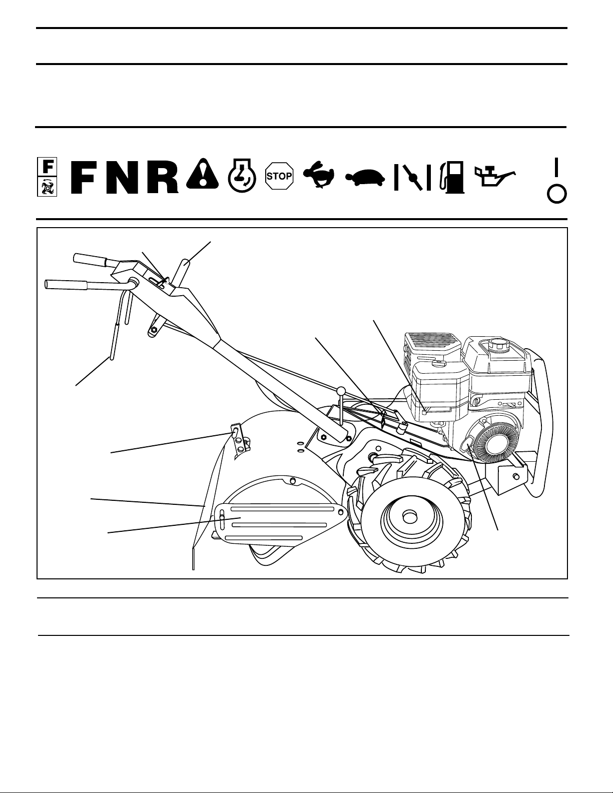
KNOW YOUR TILLER
READ THIS OWNER'S MANUAL AND SAFETY RULES BEFORE OPERATING YOUR TILLER.
Compare the illustrations with your tiller to familiarize yourself with the location of various controls and adjustments. Save
this manual for future reference.
These symbols may appear on your Tiller or in literature supplied with the product. Learn and understand their
meaning.
RUN
TILLING FORWARD NEUTRAL REVERSE FAST SLOWENGINEONENGINE
THROTTLE
CONTROL
DRIVE
CONTROL
BAR
DEPTH STAKE
CAUTION
OR WARNING
SHIFT LEVER
OFF
SHIFT LEVER INDICATOR
CHOKE CONTROL
OILFUELCHOKE
STOP
LEVELING
SHIELD
OUTER
SIDE
SHIELD
MEETS ANSI SAFETY REQUIREMENTS
Our tillers conform to the safety standards of the American National Standards Institute.
CHOKE CONTROL - Used when starting a cold engine.
DEPTH STAKE - Controls depth at which tiller will dig.
DRIVE CONTROL BAR - Used to engage tines.
LEVELING SHIELD - Levels tilled soil.
OUTER SIDE SHIELD - Adjustable to protect small plants
from being buried.
RECOIL
STARTER
HANDLE
FIG. 8
RECOIL STARTER HANDLE - Used to start the engine.
SHIFT LEVER - Used to shift transmission gears.
SHIFT LEVER INDICATOR - Shows which gear the trans-
mission is in.
THROTTLE CONTROL - Controls engine speed.
.
8
OPERATION
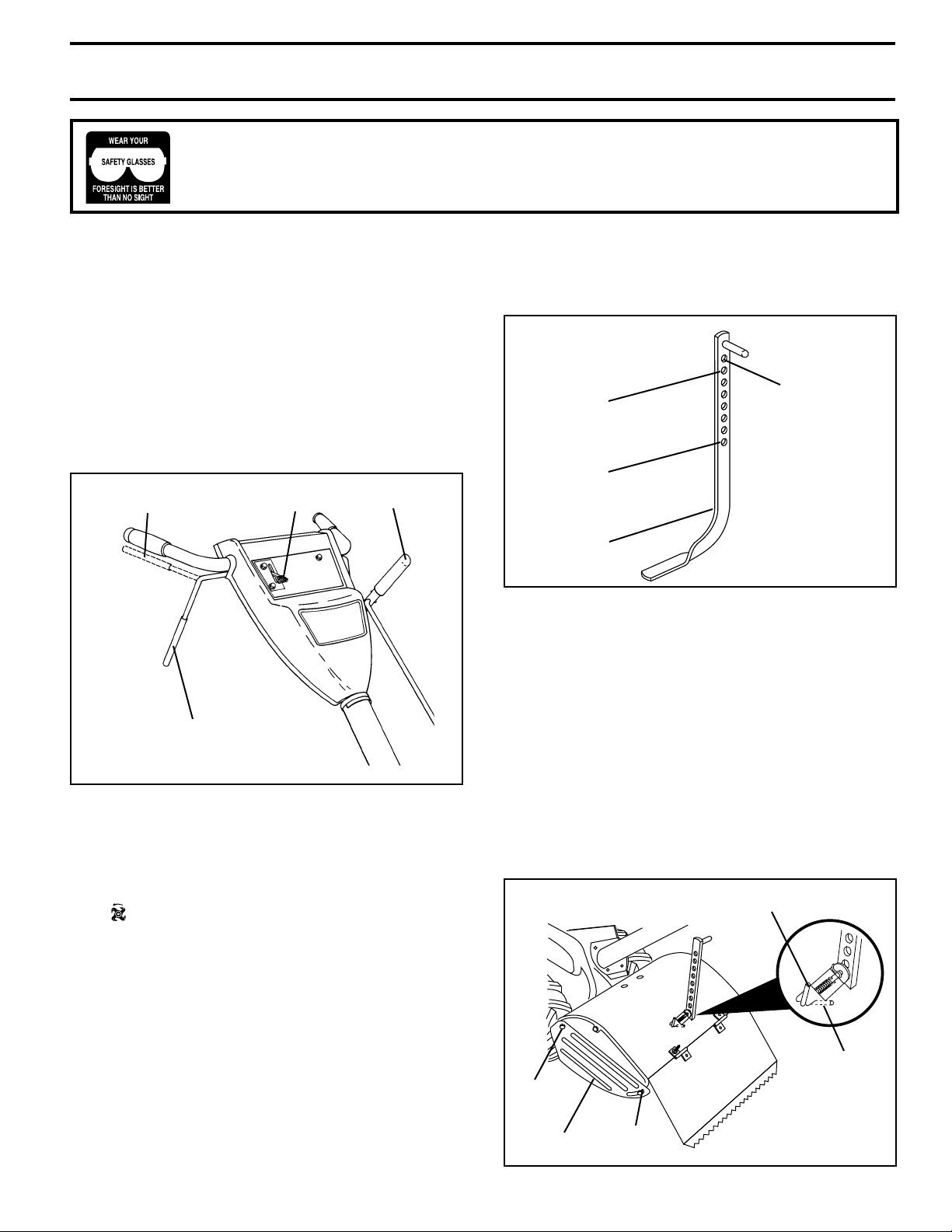
The operation of any tiller can result in foreign objects thrown into the eyes, which can
result in severe eye damage. Always wear safety glasses or eye shields before starting
your tiller and while tilling. We recommend a wide vision safety mask for over spectacles
or standard safety glasses.
HOW TO USE YOUR TILLER
Know how to operate all controls before adding fuel and
oil or attempting to start engine.
STOPPING (See Fig. 9)
TINES AND DRIVE
• Release drive control bar to stop movement.
• Move shift lever to “N” (neutral) position.
ENGINE
• Move throttle control to “STOP” position.
• Never use choke to stop engine.
DRIVE CONTROL BAR
“ENGAGED” POSITION
DRIVE CONTROL BAR
“DISENGAGED” POSITION
THROTTLE
CONTROL
FIG. 9
TINE OPERATION - WITH WHEEL DRIVE
• Always release drive control bar before moving shift
lever into another position.
• Tine movement is achieved by moving shift lever to
( ) till position and engaging drive control bar.
SHIFT
LEVER
DEPTH STAKE (See Fig. 10)
The depth stake can be raised or lowered to allow you more
versatile tilling and cultivating, or to more easily transport
your tiller.
TRANSPORT
SHALLOWEST
TILLING
(CULTIVATING)
DEEPEST
TILLING
DEPTH
STAKE
POSITION
FIG. 10
TILLING (See Fig. 11)
• Release depth stake pin. Pull the depth stake up for
increased tilling depth. Place depth stake pin in hole of
depth stake to lock in position.
• Place shift lever indicator in tilling position.
• Hold the drive control bar against the handle to start
tilling movement. Tines and wheels will both turn.
• Move throttle control to “FAST” position for deep tilling.
To cultivate, throttle control can be set at any desired
speed, depending on how fast or slow you wish to
cultivate.
IMPORTANT: ALWAYS RELEASE DRIVE CONTROL BAR
BEFORE MOVING SHIFT LEVER INTO ANOTHER
POSITION.
DEPTH STAKE PIN
“RELEASED” POSITION
FORWARD - WHEELS ONLY/TINES STOPPED
• Release drive control bar and move shift lever indicator
to “F” (forward) position. Engage drive control bar and
tiller will move forward.
REVERSE - WHEELS ONLY/TINES STOPPED
• DO NOT STAND DIRECTLY BEHIND TILLER.
• Release the drive control bar.
• Move throttle control to “SLOW” position.
• Move shift lever indicator to “R” (reverse) position.
• Hold drive control bar against the handle to start tiller
movement.
9
“LOCKED”
POSITION
NUT “B”
NUT “A”OUTER
SIDE SHIELD
FIG. 11
 Loading...