

Husqvarna 544921801 User Manual
the fastest way to purchase parts
www.speedepart.com
™
OWNERS MANUAL
MANUAL DEL USUARIO
MANUEL DU PROPRIÉTAIRE
BEDIENUNGSANLEITUNG
MANUALE DEL PR OPRIETARIO
Model No.
Modelo nº
Modèle nº
Modell-Nr.
Modello nº
LST42C-669
CAUTION:
Read Rules for Safe Operation
and Instructions Carefully
PRECAUCIÓN:
Lea cuidadosamente las
instrucciones y las reglas para
una operación segura
AVERTISSEMENT :
Lire et suivre attentivement les
instructions et consignes de
sécurité
AACHTUNG:
Lesen Sie bitte sowohl die
Hinweise zum sicheren Betrieb
sowie auch die Anweisungen
sorgfältig durch
ATTENZIONE:
Leggere attentamente le norme
di sicurezza e le istruzioni
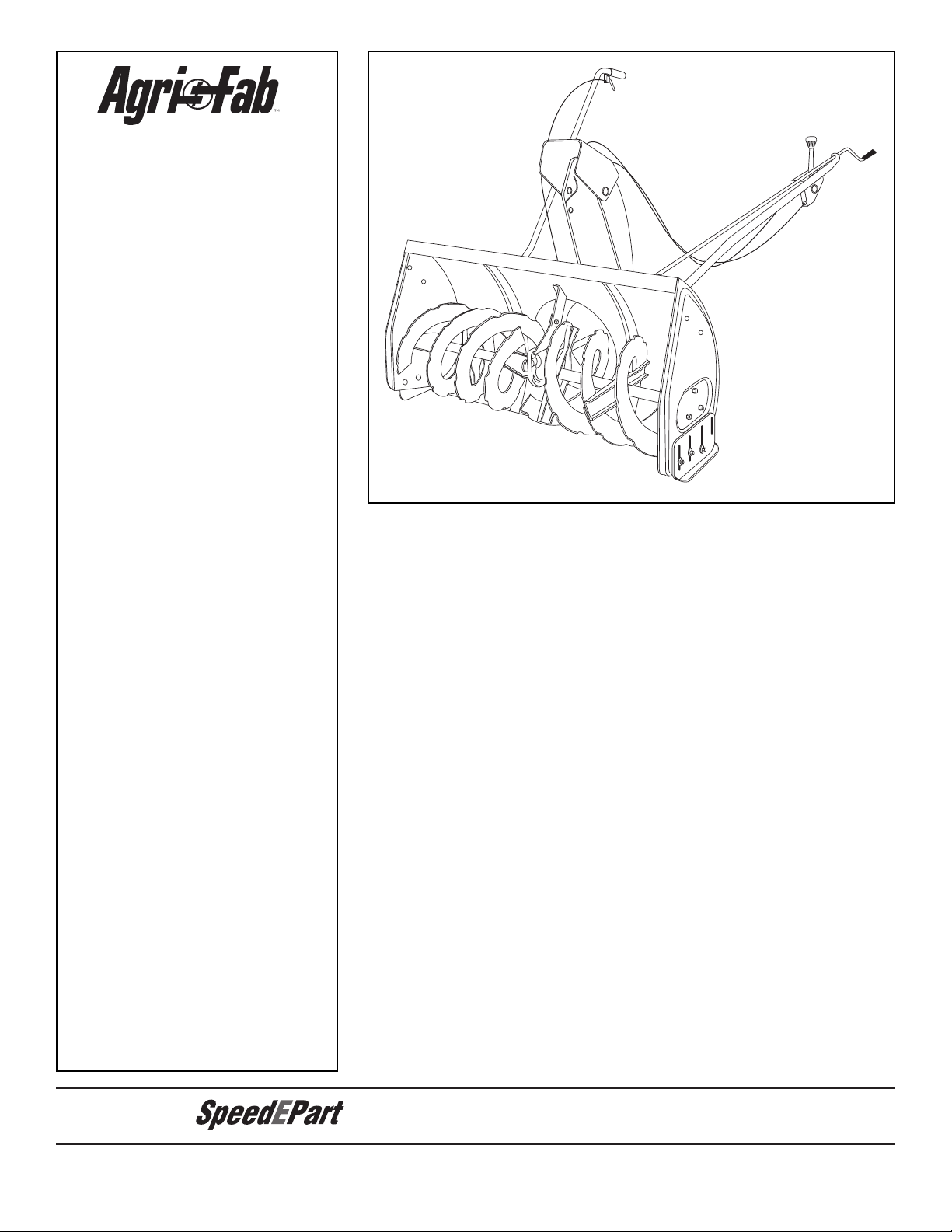
42" SNOW THROWER
SOPLADOR DE NIEVE DE 42" (106 cm)
SOUFFLEUSE À NEIGE 42 PO. (106 cm)
SCHNEEFRÄSE 42" (106 cm)
SPARTINEVE A TURBINA 42" (106 cm)
• Safety
• Assembly
• Operation
• Maintenance
• Seguridad
• Montaje
• Funcionamiento
• Mantenimiento
• Sécurité
• Assemblage
• Utilisation
• Entretien
• Sicherheit
• Zusammenbau
• Betrieb
• Wartung
• Sicurezza
• Montaggio
• Funzionamento
• Manutenzione
PRINTED IN U.S.A. FORM NO. 40429 (REV. 1/7/08)
E
B
D
G
H
I
K
O
F
X
U
Y
C
W
L
Q
S,T
R
Z
KK
EE
N
CC
BB
AA
DD
M
J
JJ
FF
GG
II
V
P
HH
A
LL
NN
MM
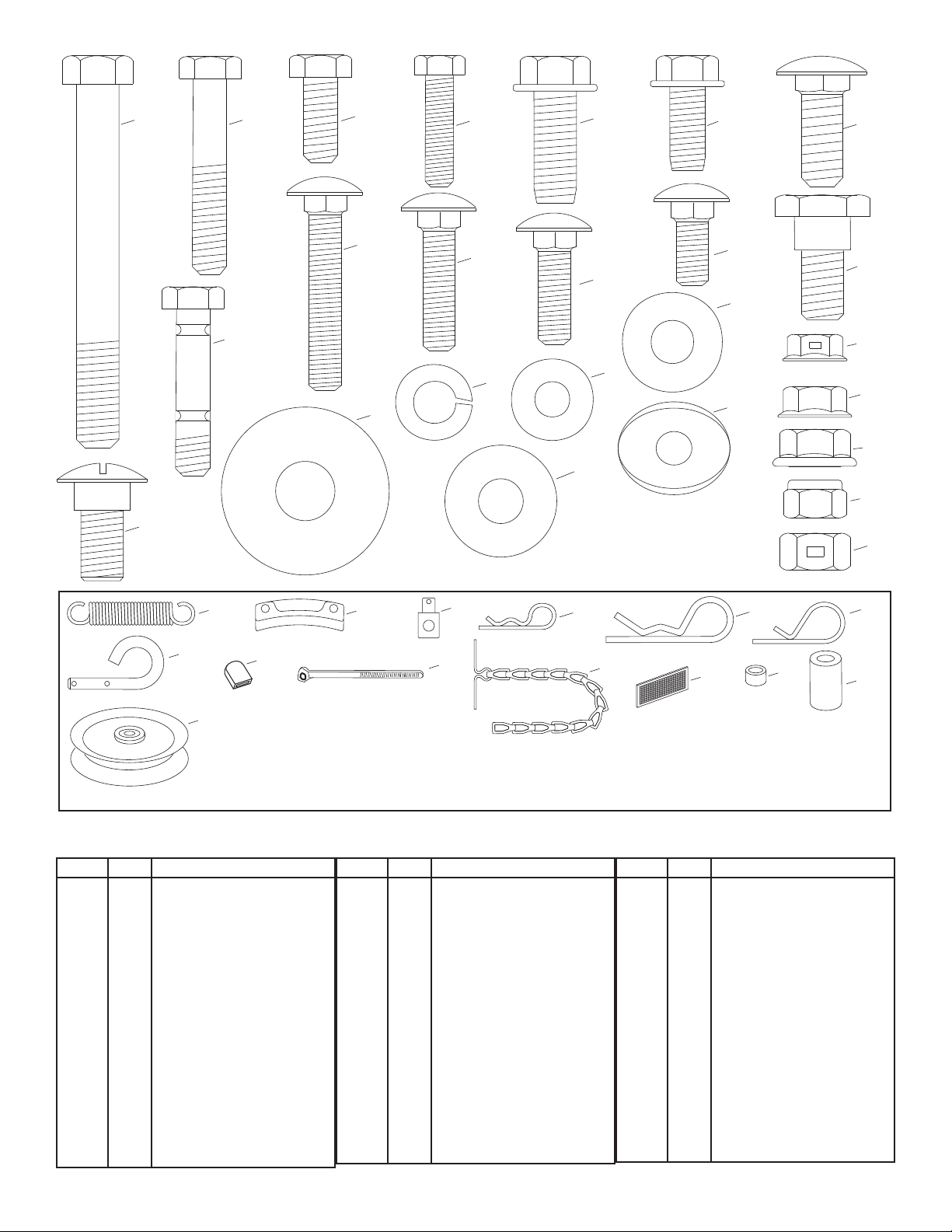
REF. QTY DESCRIPTION
A 1 Hex Bolt, 3/8" x 3-1/4"
B 2 Hex Bolt, 5/16" x 1-3/4"
C 4 Hex Bolt, 5/16" x 3/4"
D 6 Hex Bolt, 1/4" x 1"
E 6 Hex Bolt, 3/8" x 1" (Thread
Forming)
F 2 Hex Bolt, 5/16" x 3/4"
(Thread Forming)
G 6 Carriage Bolt, 3/8" x 1"
H 2 Carriage Bolt, 5/16" x
I 2 Carriage Bolt , 5/16" x
J 4 Carriage Bolt, 5/16" x 1"
K 2 Carriage Bolt, 5/16" x 3/4"
1-3/4"
1-1/4"
REF. QTY DESCRIPTION
L 4 Shoulder Bolt
M 2 Shoulder Bolt
N 2 Shear Bolt (spare parts)
O 7 Lock Washer, 3/8"
P 7 Washer, 1/4"
Q 6 Washer, 5/16"
R 8 Washer, 1/2"
S 1 Washer, 3/8" (Thin)
T 3 Washer, 3/8"
U 2 Bowed Washer
V 6 Flanged Nut, 1/4"
W 1 Flanged Nut, 5/16"
X 10 Flanged Nut, 3/8"
Y 17 Nylock Nut, 5/16" (2 spare
parts)
REF. QTY DESCRIPTION
Z 2 Hex Lock Nut, 3/8"
AA 1 Spring
BB 3 Chute Keeper
CC 1 Trunnion
DD 2 Hairpin Cotter, 5/64"
EE 4 Hairpin Cotter, 1/8"
FF 1 Hairpin Cotter, 3/32"
GG 2 Lock Pin
HH 1 Plastic Cap
II 2 Nylon Tie
JJ 2 Chain, Tensioning
KK 2 Tail Reector
LL 1 Small Spacer
MM 1 Large Spacer
NN 1 Pulley
2
REF. CANT. DESCRIPCIÓN
A 1 Tuerca hexagonal de 3/8”
x 3-1/4"
B 2 Tuerca hexagonal de
5/16” x 1-3/4"
C 4 Tuerca hexagonal de
5/16" x 3/4"
D 6 Perno de cabeza
hexagonal de 1/4” x 1"
E 6 Perno de cabeza
hexagonal de 3/8” x 1"
(auto-roscante)
F 2 Perno de cabeza
hexagonal de 5/16” x 3/4"
(auto-roscante)
G 6 Perno de cabeza de
hongo y cuello cuadrado
de 3/8" x 1"
H 2 Perno de cabeza de
hongo y cuello cuadrado
de 5/16 x 1-3/4"
I 2 Perno de cabeza de
hongo y cuello cuadrado
de 5/16 x 1-1/4"
REF. CANT. DESCRIPCIÓN
J 4 Perno de cabeza de
hongo y cuello cuadrado
de 5/16” x 1"
K 2 Perno de cabeza de
hongo y cuello cuadrado
de 5/16 x 3/4"
L 4 Perno de tope
M 2 Perno de tope
N 2 Perno de seguridad
(piezas de repuesto)
O 7 Arandela de presión de
3/8"
P 7 Arandela de 1/4"
Q 6 Arandela de 5/16"
R 8 Arandela de 1/2"
S 1 Arandela de 3/8"
(delgada)
T 3 Arandela de 3/8"
U 2 Arandela curvada
V 6 Tuerca con brida de 1/4"
W 1 Tuerca con brida de 5/16"
X 10 Tuerca con brida de 3/8"
REF. CANT. DESCRIPCIÓN
Y 17 Tuerca Nylock de 5/16" (2
piezas de repuesto)
Z 2 Tuerca hexagonal de
cierre de 3/8
AA 1 1 resorte
BB 3 Sujetador del conducto
CC 1 Muñón de sujeción
DD 2 Pasador de horquilla de
5/64"
EE 4 Pasador de horquilla de
1/8"
FF 1 Pasador de horquilla de
3/32"
GG 2 Pasador de traba
HH 1 Tapa plástica
II 2 Tirante de Nylon
JJ 2 Cadena, tensora
KK 2 Reector de cola
LL 1 Espaciador pequeño
MM 1 Espaciador grande
NN 1 Polea
RÉF. QTÉ DESCRIPTION
A 1 Boulon hex., 3/8 x 3-1/4 po.
B 2 Boulon hex., 5/16 x 1-3/4 po.
C 4 Boulon hex., 5/16 x 3/4 po.
D 6 Boulon hex., 1/4 x 1 po.
E 6 Boulon hex., 3/8 x 1 po.
(auto-taraudeur)
F 2 Boulon hex., 5/16 x 3/4 po.
(auto-taraudeur)
G 6 Boulon de carrosserie, 3/8
x 1 po.
H 2 Boulon de carrosserie, 5/16
x 1-3/4 po.
I 2 Boulon de carrosserie , 5/16
x 1-1/4 po.
J 4 Boulon de carrosserie, 5/16
x 1 po.
K 2 Boulon de carrosserie, 5/16
x 3/4 po.
L 4 Boulon à épaulement
RÉF. QTÉ DESCRIPTION
M 2 Boulon à épaulement
N 2 Boulon de cisaillement
(pièces de rechange)
O 7 Rondelle de blocage, 3/8 po.
P 7 Rondelle, 1/4 po.
Q 6 Rondelle, 5/16 po.
R 8 Rondelle, 1/2 po.
S 1 Rondelle, 3/8 po. (ne)
T 3 Rondelle, 3/8 po.
U 2 Rondelle frein
V 6 Écrou à embase, 1/4 po.
W 1 Écrou à embase, 5/16 po.
X 10 Écrou à embase, 3/8 po.
Y 17 Écrou mécanique de
sécurité, 5/16 po. (2 pièces
de rechange)
Z 2 Écrou de blocage hex. 3/8
po.
RÉF. QTÉ DESCRIPTION
AA 1 1 Ressort
BB 3 Gâches de la goulotte
d’éjection
CC 1 Tourillon
DD 2 Goupille fendue, 5/64 po.
EE 4 Goupille fendue, 1/8 po.
FF 1 Goupille fendue, 3/32 po.
GG 2 Axe de blocage
HH 1 Capuchon en plastique
II 2 Attache en nylon
JJ 2 Chaîne de tension
KK 2 Catadioptre arrière
LL 1 Petite rondelle d’espacement
MM 1 Grande rondelle
d’espacement
NN 1 Poulie
3
BEZ. ANZ. BESCHREIBUNG
A 1 Sechskantschraube, 3/8"
x 3-1/4"
B 2 Sechskantschraube, 5/16"
x 1-3/4"
C 4 Sechskantschraube, 5/16"
x 3/4"
D 6 Sechskantschraube, 1/4"
x 1"
E 6 Sechskantschraube, 3/8" x
1" (gewindeschneidend)
F 2 Sechskantschraube,
5/16" x 3/4"
(gewindeschneidend)
G 6 Schlossschraube, 3/8" x 1"
H 2 Schlossschraube, 5/16" x
1-3/4"
I 2 Schlossschraube, 5/16" x
1-1/4"
J 4 Schlossschraube, 5/16"
x 1"
BEZ. ANZ. BESCHREIBUNG
K 2 Schlossschraube, 5/16"
x 3/4"
L 4 Gelenkschraube
M 2 Gelenkschraube
N 2 Scherschraube
(Ersatzteile)
O 7 Sicherungsscheibe, 3/8"
P 7 Unterlegscheibe, 1/4"
Q 6 Unterlegscheibe, 5/16"
R 8 Unterlegscheibe, 1/2"
S 1 Unterlegscheibe, 3/8"
(dünn)
T 3 Unterlegscheibe, 3/8"
U 2 Gewölbte Unterlegscheibe
V 6 Flanschmutter, 1/4"
W 1 Flanschmutter, 5/16"
X 10 Flanschmutter, 3/8"
Y 17 Sechskantmutter mit
Klemmteil, 5/16" (2
Ersatzteile)
BEZ. ANZ. BESCHREIBUNG
Z 2 Sechskantsicherungsmut
ter, 3/8"
AA 1 1 Feder
BB 3 Leitblechhalterung
CC 1 Zapfen
DD 2 Haarnadelsplint, 5/64"
EE 4 Haarnadelsplint, 1/8"
FF 1 Haarnadelsplint, 3/32"
GG 2 Steckbolzen
HH 1 Plastikkappe
II 2 Kabelbinder
JJ 2 Spannkette
KK 2 Rückwärtiger Reektor
LL 1 Kleines Distanzstück
MM 1 Großes Distanzstück
NN 1 Riemenscheibe
RIF. QTÀ. DESCRIZIONE
A 1 Bullone esagonale da 3/8"
x 3-1/4"
B 2 Bullone esagonale da 5/16"
x 1-3/4"
C 4 Bullone esagonale da 5/16"
x 3/4"
D 6 Bullone esagonale da 1/4"
x 1"
E 6 Bullone esagonale da 3/8" x
1" (autolettante)
F 2 Bullone esagonale da 5/16"
x 3/4" (autolettante)
G 6 Chiavarda a testa rotonda
da 3/8" x 1"
H 2 Chiavarda a testa rotonda
da 5/16" x 1-3/4"
I 2 Chiavarda a testa rotonda
da 5/16" x 1-1/4"
J 4 Chiavarda a testa rotonda
da 5/16" x 1"
RIF. QTÀ. DESCRIZIONE
K 2 Chiavarda a testa rotonda
da 5/16" x 3/4"
L 4 Vite con gambo
parzialmente lettato
M 2 Vite con gambo
parzialmente lettato
N 2 Perno di sicurezza (pezzi di
ricambio)
O 7 Rondella elastica da 3/8"
P 7 Rondella da 1/4"
Q 6 Rondella da 5/16"
R 8 Rondella da 1/2"
S 1 Rondella da 3/8" (Thin)
T 3 Rondella da 3/8"
U 2 Rondella arcuata
V 6 Dado a colletto da 1/4"
W 1 Dado a colletto da 5/16"
X 10 Dado a colletto da 3/8"
RIF. QTÀ. DESCRIZIONE
Y 17 Dado Nylock da 5/16" (2
parti di ricambio)
Z 2 Controdado esagonale da
3/8"
AA 1 1 molla
BB 3 Fissatore dello scivolo
CC 1 Perno di articolazione
DD 2 Chiavetta a forcella da 5/64"
EE 3 Chiavetta a forcella da 1/8"
FF 1 Chiavetta a forcella da 3/32"
GG 2 Spinotto di bloccaggio
HH 1 Tappo di plastica
II 2 Tirante di plastica
JJ 2 Catena, Messa in tensione
KK 2 Riettore di coda
LL 1 Piccolo distanziale
MM 1 Grande distanziale
NN 1 Puleggia
4
14
1
2
4
5
6
12
9
8
10
20
19
11
17
16
15
18
13
7
3
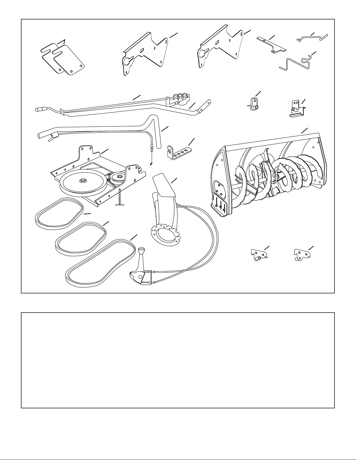
CARTON CONTENTS
1. Suspension Arms (2)
2. Left Hand Side Plate
3. Right Hand Side Plate
4. Anti-rotation Bracket
5. Engagement Rod (Not used on some models)
6. Engine Pulley Keeper (Not used on some models)
7. Chute Crank Rod Assembly
8. Support Tube, Crank Rod
9. Lift Handle and Cable
10. Cable Bracket
11. L.H. Hanger Bracket (Outside Mounting)
12. R.H. Hanger Bracket (Outside Mounting)
13. Clutch Idler Assembly
14. V-Belt, Drive (Short) #46989
15 V-Belt, Drive (Long) #48138
16. V-Belt, Auger (Attached to Housing Assembly)
17. Chute and Control Cable Assembly
18. Housing Assembly
19. L.H. Hanger Bracket (Inside Mounting)
20. R.H. Hanger Bracket (Inside Mounting)
Hardware Package (Stored inside Plastic Keg)
5

CONTENIDO DE LA CAJA
1. Brazos de suspensión (2)
2. Placa lateral izquierda
3. Placa lateral derecha
4. Soporte antirrotación
5. Varilla de enganche (No se utiliza en algunos modelos)
6. Sujetador de la polea motor (No se utiliza en algunos
modelos)
7. Conjunto varilla manivela del conducto
8. Tubo soporte, varilla de la manivela
9. Manivela de elevación y cable
10. Soporte para el cable
11. Soporte de suspensión lado izquierdo (Se monta en el
exterior)
12. Soporte de suspensión lado derecho (Se monta en el
exterior)
13. Conjunto de embrague/polea libre
14. Correa trapezoidal, transmisión (corta) #46989
15. Correa trapezoidal, transmisión (larga) #48138
16. Correa trapezoidal, barrena (enganchada al conjunto de la
carcasa)
17. Conjunto de cable de control y de conducto.
18. Carcasa
19. Soporte de suspensión lado izquierdo (Se monta en el
interior)
20. Soporte de suspensión lado derecho (Se monta en el
interior)
Paquete de accesorios (se guarda en el interior de una bolsa
de plástico)
CONTENU DU CARTON
1. Bras de suspension (2)
2. Plaque latérale gauche
3. Plaque latérale droite
4. Patte anti-rotation
5. Biellette de mise en prise (n'est pas utilisée sur certains
modèles)
6. Gâche de la poulie du moteur (n'est pas utilisée sur certains
modèles)
7. Bielle de la goulotte d’éjection
8. Tube de support de la bielle de la goulotte
9. Poignée d’élévation et câble
10. Support de xation du câble
INHALT DES KARTONS
1. Aufhängungsarme (2)
2. Linke Seitenplatte
3. Rechte Seitenplatte
4. Verdrehschutzhalterung
5. Einrückstange (kommt nicht bei allen Modellen zum
Einsatz)
6. Keilriemenhalter (kommt nicht bei allen Modellen zum
Einsatz)
7. Leitblechverstellstangenbaugruppe
8. Stützrohr, Verstellstange
9. Hebergriff und Kabel
11. Support suspendu gauche (montage extérieur)
12. Support suspendu droit (montage extérieur)
13. Ensemble embrayage et galet tendeur
14. Petite courroie en V du mécanisme d’entraînement no.
46989
15. Longue courroie en V du mécanisme d’entraînement no.
48138
16. Courroie en V de la tarière (xée au carter de protection)
17. Ensemble de la goulotte d’éjection et du câble de
commande
18. Carter de protection
19. Support suspendu gauche (montage intérieur)
20. Support suspendu droit (montage intérieur)
Sac de pièces de quincaillerie (située à l’intérieur d’un baril en
plastique)
10. Kabelkonsole
11. linke Hängerhalterung (Außenmontage)
12. rechte Hängerhalterung (Außenmontage)
13. Kupplungs-/Umlenkrollenbaugruppe
14. Keilriemen, Antrieb (kurz) Nr. 46989
15 Keilriemen, Antrieb (lang) Nr. 48138
16. Keilriemen, Schnecke (Mit der Gehäusebaugruppe
verbunden)
17. Leitblech- und Steuerkabelbaugruppe
18. Gehäusebaugruppe
19. linke Hängerhalterung (Innenmontage)
20. rechte Hängerhalterung (Innenmontage)
Kleinteilepackung (im Plastikfass untergebracht)
CONTENUTO DEI CARTONI
1. Bracci di sospensione (2)
2. Piastra laterale sinistra
3. Piastra laterale destra
4. Staffa antirotazione
5. Asta di inserimento (Non usato in alcuni modelli)
6. Fissatore della puleggia motrice (Non usato in alcuni
modelli)
7. Gruppo asta manovella dello scivolo
8. Tubo di supporto, Asta manovella
9. Maniglia e cavo di sollevamento
10. Staffa del cavo
11. Staffa del gancio sinistro (montaggio esterno)
12. Staffa del gancio destro (montaggio esterno)
13. Gruppo innesto ingranaggio folle
14. Cinghia a V, motrice (corta) no.46989
15 Cinghia a V, motrice (lunga) no. 48138
16. Cinghia a V, Coclea (Attaccata al gruppo
alloggiamento)
17. Gruppo scivolo e cavo di comando
18. Gruppo alloggiamento
19. Staffa del gancio sinistro (montaggio interno)
20. Staffa del gancio destro (montaggio interno)
Pacchetto bulloneria (conservato all’interno del barilotto
di plastica)
6

SAFETY
Any power equipment can cause injury if operated improperly or if the user does not understand how to operate the equipment.
Exercise caution at all times, when using power equipment.
• Read this owner's manual carefully and know how to
operate your snow thrower and how to stop the unit and
disengage the controls quickly.
• Never allow children to operate the equipment.
• Never allow adults to operate the equipment without
proper instruction.
• Keep the area of operation clear of all persons, especially
small children, and pets.
• Thoroughly inspect the area where the equipment is to
be used and remove all door mats, sleds, boards, wires
and other foreign objects.
• Disengage all clutches and shift into neutral before
starting engine.
• Do not operate equipment without wearing adequate
winter outer garments.
• Wear substantial footwear which will protect feet and
improve footing on slippery surfaces.
• Check fuel before starting the engine. Do not remove the
fuel cap or ll the fuel tank while the engine is running
or hot. Do not ll the fuel tank indoors. Gasoline is an
extremely ammable fuel.
• Make sure the snow thrower height is adjusted to clear
the type surface it will be used on.
• Do not use the snow thrower without the rear weight
attached to the tractor.
• Never make any adjustments while the engine is
running.
• Always wear safety glasses or eye shield during operation
or while performing adjustment or repair.
• Do not place hands or feet near rotating parts. Keep
clear of the discharge opening at all times.
• Use extreme caution when operating on or crossing
gravel surfaces.
• Do not carry passengers.
• After striking a foreign object, stop the engine, remove
the wire from the spark plug and then thoroughly inspect
the snow thrower for damage. Repair any damage before
restarting and operating the snow thrower.
• If the snow thrower starts to vibrate abnormally, stop the
engine immediately and check for the cause. Vibration
is generally a warning of trouble.
• Stop the engine whenever you leave the operating
position, before unclogging the snow thrower or making
any adjustments or inspections.
• Take all possible precautions when leaving the unit
unattended. Disengage the attachment clutch lever or
switch, lower the snow thrower, shift into neutral, set the
parking brake, stop the engine and remove the key.
• When cleaning, repairing or inspecting, make certain all
moving parts have stopped. Disconnect the spark plug
wire and keep it away from the plug to prevent accidental
starting.
• Do not run engine indoors except when transporting the
snow thrower in or out of the building. Open the outside
doors. Exhaust fumes are dangerous.
• Do not clear snow across the face of slopes. Exercise
extreme caution when changing direction on slopes.
Do not attempt to clear steep slopes. Refer to the slope
guide on page 79 of this manual.
• Never operate the snow thrower without guards, plates
or other safety protection devices in place.
• Never operate the snow thrower near glass enclosures,
automobiles, window wells, drop offs etc. without proper
adjustment of the snow thrower discharge angle.
• Never direct discharge at bystanders or allow anyone in
front of the snow thrower.
• Never run the snow thrower into material at high
speeds.
• Do not overload the machine capacity by attempting to
clear snow at too fast a rate.
• Never operate the machine at high transport speed
on slippery surfaces. Look behind and use care when
backing up.
• Watch for trafc and stay alert when crossing or operating
near roadways.
• Disengage power to the snow thrower when transporting
or when not in use.
• Use only attachments and accessories approved by
the manufacturer of the snow thrower (such as wheel
weights, counter weights, cabs etc.)
• Never operate the snow thrower without good visibility
or light.
IMPORTANT:
Rear wheel weights and tire chains are required to
provide extra traction and stability when using this
snow thrower attachment. These items are available
where you purchased your tractor.
WHEEL WEIGHTS TIRE CHAINS
7
REMOVE
FRONT SCREWS
REMOVE
BROWNING SHIELD
MOWER DECK
SUSPENSION
BRACKET
ASSEMBLY
TOOLS REQUIRED FOR ASSEMBLY
(2) 7/16" Wrenches
(2) 1/2" Wrenches
(2) 9/16" Wrenches
(2) 3/4" Wrenches
(1) Screw Driver
(1) Knife
ADDITIONAL ITEMS REQUIRED
General Purpose Grease
REMOVAL OF PARTS FROM CARTON
• Remove all parts and hardware packages from the
carton. Lay out parts and hardware and identify using
the illustrations on pages 2 and 5.
NOTE: Not all of the supplied parts and hardware will be
needed for your particular tractor. Unneeded items may
be discarded after you have completed assembly and
checked operation of unit. DO NOT DISCARD the two
spare shear bolts (N) and 5/16" nylock nuts (Y). Refer to
the Service and Adjustments section on page 28.
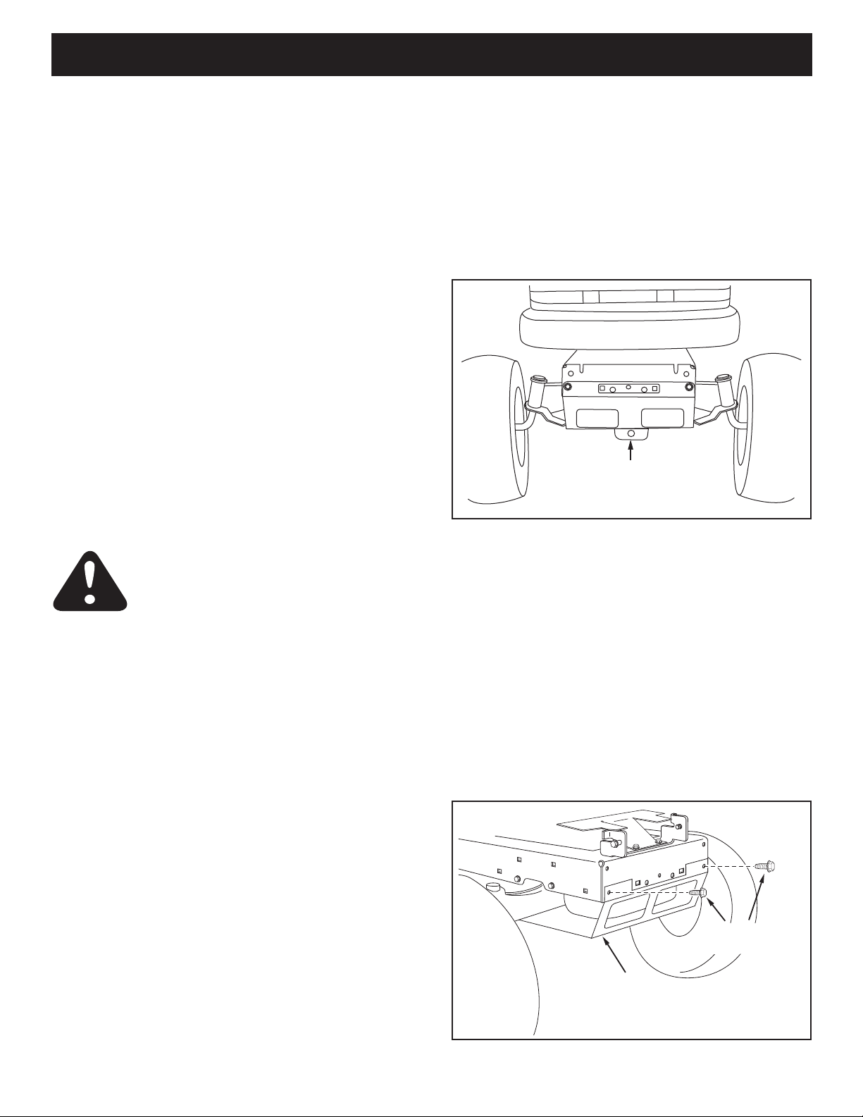
IDENTIFY YOU TRACT OR
STEP 1: (SEE FIGURE 1)
• Look under the front of your tractor. If there is a single
mower deck suspension bracket located underneath
the middle of the front axle, continue on to step 2.
If your tractor does not have a mower deck
suspension bracket underneath the middle of the
front axle, skip to step 21 on page 14 for tractors
with dual suspension brackets.
CAUTION: Before starting to assemble the
snow thrower, remove the spark plug wire(s),
set the parking brake and remove the key
from the tractor ignition.
TRACTOR PREPARATION
Before performing these instructions, refer to the Service
and Adjustments section of your tractor owner's manual
for specic safety instructions.
• Allow engine, mufer and exhaust deector to cool
before beginning.
• Remove any front or rear attachment which is
mounted to your tractor.
• Remove the mower deck. Refer to your tractor owner's
manual for removal instructions. Mark all loose parts
and save for reassembly.
• Remove the tractor hood. Refer to your tractor owner's
manual for removal instructions.
FIGURE 1
INSTRUCTIONS FOR TRACTORS WITH
SINGLE FRONT DECK SUSPENSION
BRACKET
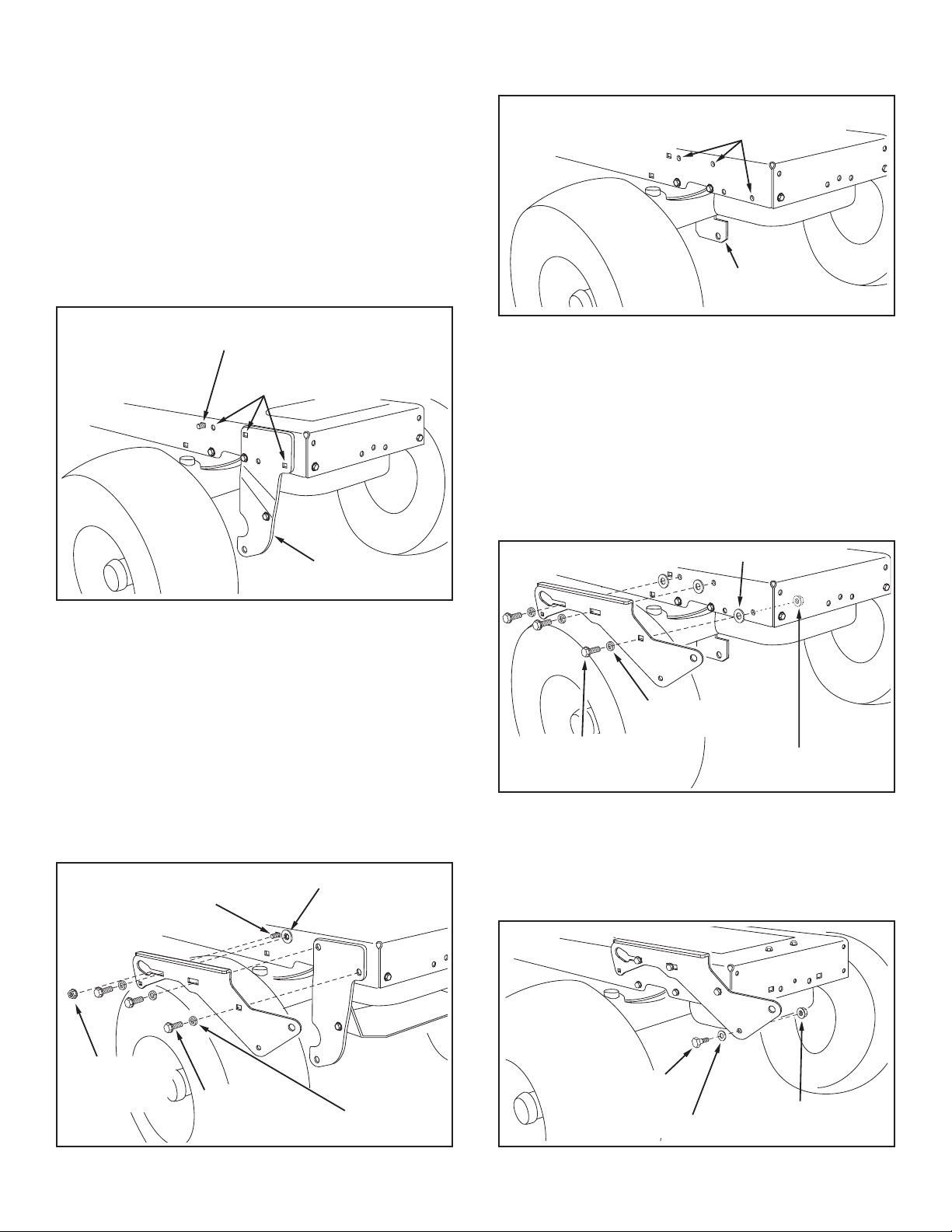
STEP 2: (SEE FIGURE 2)
• Remove the browning shield from the front of the
tractor as shown. Hold onto the shield as you remove
the second screw to prevent it from falling.
• Be sure to reinstall the browning shield when so
instructed in step 3.
IMPORTANT: Right hand (R.H.) and left hand (L.H.) side
of the tractor are determined from the operators position
while seated on the tractor.
FIGURE 2 RIGHT SIDE VIEW
8
5/16"
NYLOCK
NUT (Y)
5/16" x 1"
CARRIAGE BOLT (J)
ENGINE MOUNTING
PLATE
(4) 1/2" WASHERS (R)
(3) 3/8" FLANGE NUTS (X)
(3) 3/8" x 1"
CARRIAGE
BOLTS (G)
SEE NOTE
3/8" WASHER (T)
SHOULDER
BOLT (L)
3/8" FLANGED
NUT (X)
INSTALL SIDE PLATES
5/16" x 3/4" SELF
THREADING BOLT (F)
L.H. HANGER
BRACKET
BRAKE ROD
3/8" FLANGED
NUT (X)
SHOULDER
BOLT (M)
5/16" x 3/4" SELF
THREADING BOLT (F)
R.H. HANGER
BRACKET
RIGHT END OF
BRAKE ROD
3/8" FLANGED
NUT (X)
SHOULDER
BOLT (M)
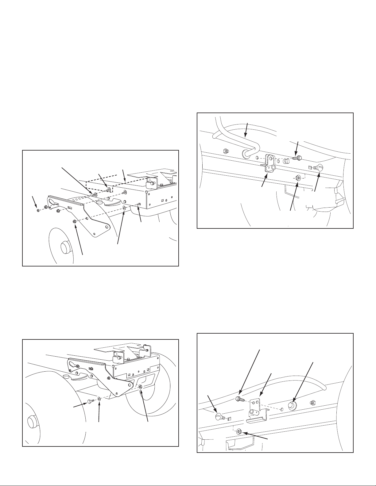
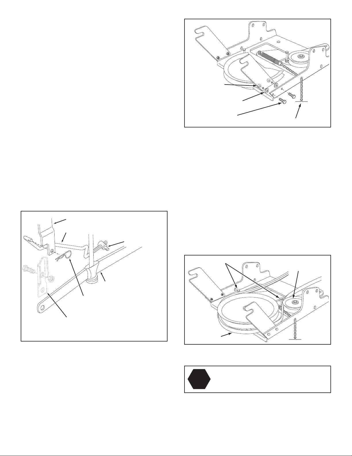
STEP 3: (SEE FIGURE 3)
• Fasten the R.H. Side Plate (bend facing out) to the
front three holes in the tractor frame using three 3/8"
x 1" carriage bolts (G), three 1/2" washers (R) (see
note) and three 3/8" ange nuts (X). For the rear hole,
use a 5/16" x 1" carriage bolt (J), a 1/2" washer (R)
and a 5/16" nylock nut (Y). Place the 1/2" washers (R)
between the tractor frame and the side plate. Repeat
for L.H. side plate.
• Reinstall the browning shield onto the tractor frame
using the original screws.
NOTE: If there is an engine mounting plate (shown with
dotted lines) leave the 1/2 washer off the bolt that goes
through the plate.
INSTALL HANGER BRACKETS AND SHOULDER
BOLTS TO OUTSIDE OF FRAME
STEP 5: (SEE FIGURE 5)
Remove the bolt, if present, in the hole directly behind
•
the brake rod on the left side of the tractor frame.
• Attach the L.H. Hanger Bracket (tube facing out) to the
hole using a 5/16" x 3/4" self threading bolt (F).
• Install a round head shoulder bolt (M) into the hole
that is 9-1/2" to the rear of the bolt you just installed.
Secure it with a 3/8" ange nut (X) on the inside of the
frame.
FIGURE 3 RIGHT SIDE VIEW
STEP 4: (SEE FIGURE 4)
• Assemble a shoulder bolt (L) and a 3/8" washer (T) to
the outside of R.H. side plate, securing it with a 3/8"
anged nut (X). Repeat for L.H. side plate.
FIGURE 5 LEFT SIDE VIEW
STEP 6: (SEE FIGURE 6)
• Remove the bracket, if present, from the hole directly
behind the end of the brake rod on the right side of
the tractor frame. Store the bracket and bolt.
• Attach the R.H. Hanger Bracket to the hole using a
5/16" x 3/4" self threading bolt (F).
• Install a round head shoulder bolt (M) into the hole
that is 9-1/2" to the rear of the bolt you just installed.
Secure it with a 3/8" ange nut (X) on the inside of the
frame.
FIGURE 4 RIGHT SIDE VIEW
FIGURE 6 RIGHT SIDE VIEW
9
3/8" X 3-1/4"
HEX BOLT
(A)
LARGE SPACER (MM)
PULLEY (NN)
3/8" LOCKWASHER (O)
3/8" HEX LOCK NUT (Z)
3/8"
WASHER (T)
LONG END
OF HUB
CABLE
BRACKET
5/16" x 3/4"
CARRIAGE BOLT (K)
5/16" NYLOCK
NUT (Y)
THIS SECTION IS FOR TRACTORS WITH A
HEX BOLTS
(#48138)
DRIVE BELT
FLAT IDLER
PULLEYS
5/16" NYLOCK
NUT (Y)
5/16" x 3/4"
HEX BOLT (C)
TENSIONING CHAIN (JJ)
MANUAL ATTACHMENT CLUTCH
If your tractor has an electric attachment clutch go to
step 14 on page 12.
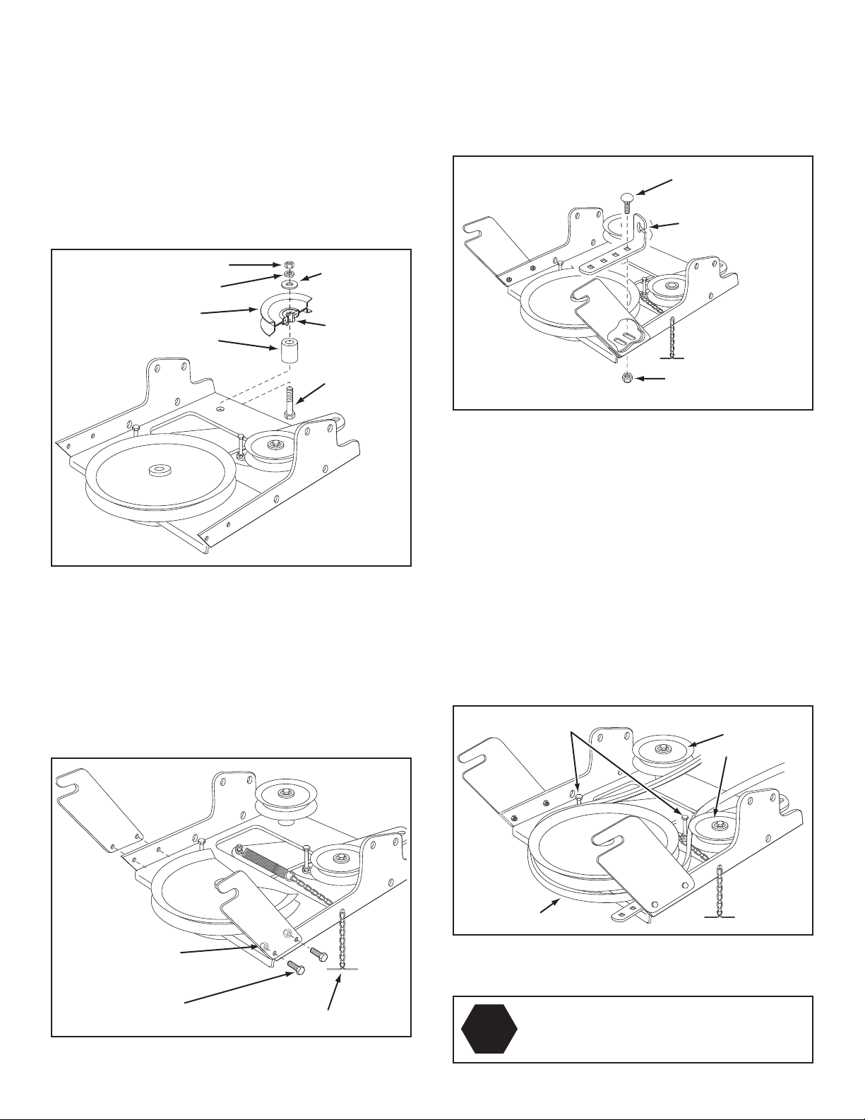
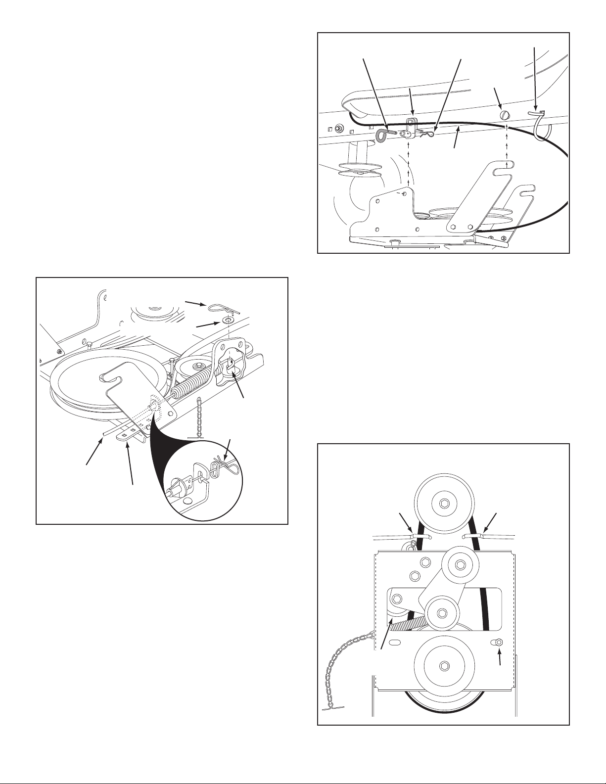
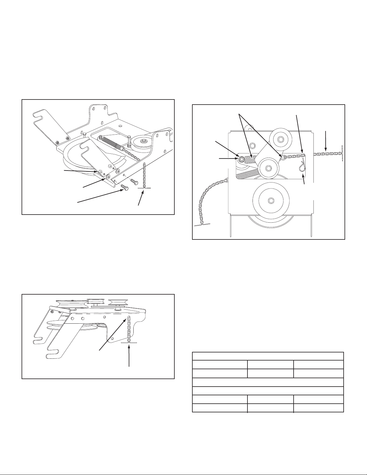
STEP 7: (SEE FIGURE 7)
• Attach the pulley (long end of hub facing down) and
the large spacer (MM) to the hole shown in the clutch/
idler assembly. Use a 3/8" x 3-1/4" hex bolt (A), a 3/8"
washer (T), a 3/8" lock washer (O) and a 3/8" hex lock
nut (Z).
STEP 9: (SEE FIGURE 9)
• Attach the cable bracket to the slot shown in the
clutch/idler assembly using a 5/16" x 3/4" carriage
bolt (K) and a 5/16" nylock nut (Y). Place the bolt in
the front hole of the bracket and in the end of the slot
closest to the pulley. Do not tighten yet.
FIGURE 9
FIGURE 7
STEP 8: (SEE FIGURE 8)
• Attach the two suspension arms to the rear of the
clutch/idler assembly using two 5/16" x 3/4" hex bolts
(C) and 5/16" nylock nuts (Y) for each arm. Place the
arms on the outside of the frame with the notches to
the rear.
• Insert a tensioning chain through the hole shown and
attach the end link to the spring on the lower idler arm.
STEP 10: (SEE FIGURE 10)
• Two different length drive belts are included with
your snow thrower. Tractors with manual attachment
clutches and single front deck suspension brackets use
the 56" drive belt with #48138 printed on the outside of
the belt. DO NOT USE the other belt.
• Slightly loosen the hex bolt next to the at idler pulley.
Install the drive belt down between the hex bolt and the
at idler pulley with the at side of the belt against the
pulley. Retighten the hex bolt.
• Loop the belt around the large v-pulley, placing it
between the v-pulley and the hex bolt next to the pulley.
Place the belt to the inside of the other at idler pulley.
FIGURE 10
FIGURE 8
10
STOP
Did you select the correct drive belt for your
tractor? Using the wrong length belt may
cause premature bearing or belt failure.
PIVOT LOCK PIN (GG)
(use this hole)
SHOULDER
BOLT (M)
L.H. HANGER
BRACKET
1/8" HAIRPIN
COTTER (EE)
NYLON TIE (II)
MOWER
CLUTCH
CABLE
ENGINE
PULLEY
ENGINE
PULLEY
Left Side
of Tractor
ENGINE
PULLEY
KEEPER
ENGINE
PULLEY
KEEPER
KEEPER BOLT
IDLER
PULLEY
5/64" HAIR
COTTER PIN (DD)
1/4" WASHER (P)
SPACER (LL)
TRACTOR'S
CLUTCH CABLE
CABLE
BRACKET
5/64" HAIR
COTTER PIN (DD)
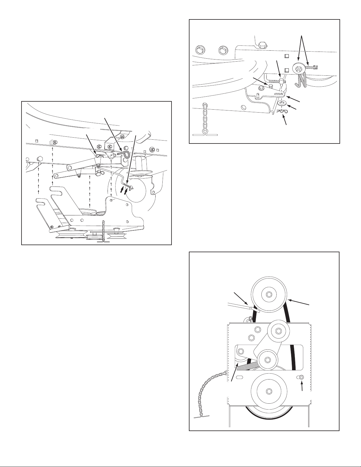
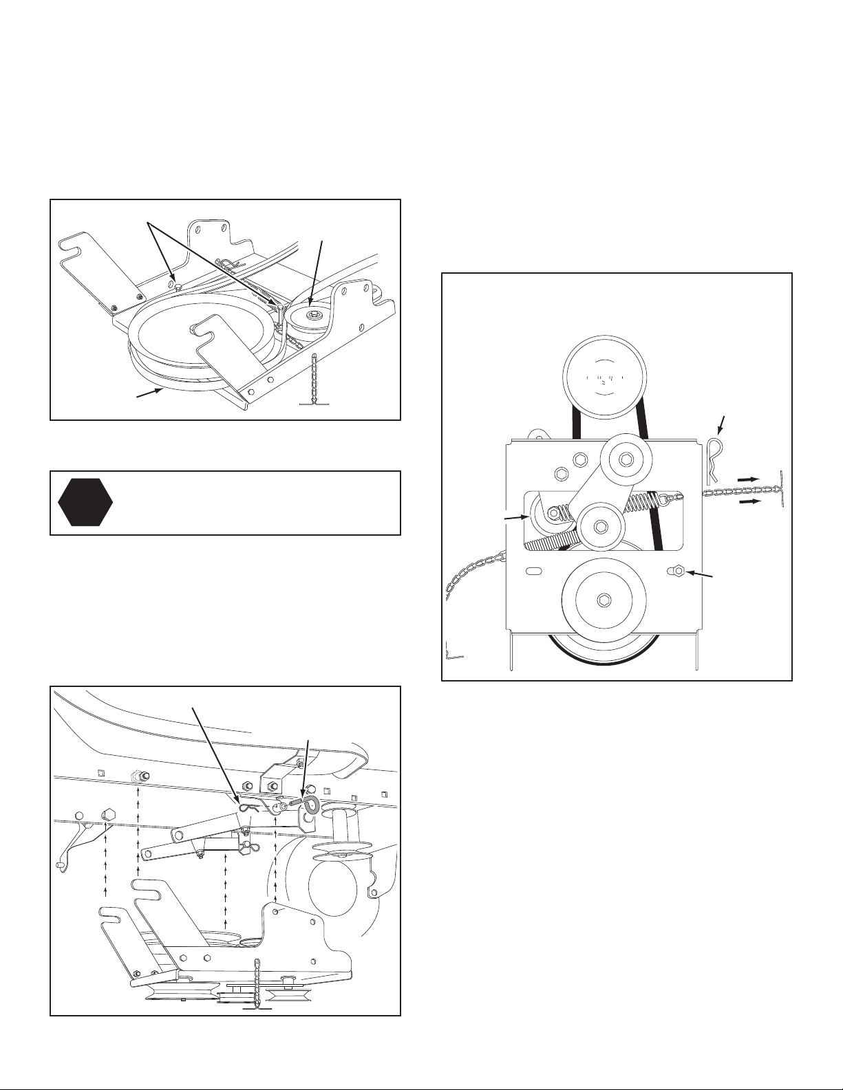
STEP 11: (SEE FIGURE 11)
• Find the cable clip that is attached to the left side
of the tractor frame underneath the footrest. Open
the clip and remove the mower clutch cable. Do not
remove the clip from the tractor frame. The cable
reattaches to the clip when using the mower deck.
• Move the attachment clutch lever on the dash panel to
the disengaged position.
• Place the clutch/idler assembly on the oor on the left
side of the tractor.
• Attach the tractor's mower clutch cable to the cable
bracket on the clutch/idler assembly. Secure the cable
housing guide (groove down) to the cable bracket
using the original collar and a 5/64" hair cotter pin (DD).
• Place a spacer (LL) on the welded pin on the idler
arm. Hook the end of the clutch cable spring over the
pin and secure it with a 1/4" washer (P) and a 5/64"
hair cotter pin (DD).
• Align cable bracket with welded pin and tighten the
nut assembled in step 9.
FIGURE 12 VIEWED FROM LEFT SIDE
STEP 13: (SEE FIGURE 13)
• Assemble the drive belt onto the engine pulley rst
and then onto the large pulley on top of the clutch/
idler assembly. The belt must be placed inside the
engine pulley belt keeper(s) and between the large
pulley and the keeper bolt next to it.
FIGURE 11
ATTACH CLUTCH IDLER ASSEMBLY TO TRACTOR
STEP 12: (SEE FIGURE 12)
• Attach the clutch/idler assembly to the tractor frame.
Hook the notched suspension arms onto the two
shoulder bolts (M) assembled to the outside of the
tractor frame. Lift the front of the assembly and attach
it to the R.H. and L.H. hanger brackets using two pivot
lock pins (GG) and 1/8" hairpin cotters (EE).
• Loosely attach the mower clutch cable to the left side
of the tractor frame with a nylon tie (II). Do not pull
the nylon tie completely tight. The cable may need to
be removed from the nylon tie when using the mower
deck.
IMPORTANT: Do Not assemble the "V" belt outside of
the engine pulley keepers or outside of the keeper bolt
next to the large pulley.
• Go to step 48 on page 21.
CLUTCH/IDLER ASSEMBLY
FIGURE 13 VIEWED FROM UNDERNEATH
11
THIS SECTION IS FOR TRACTORS WITH AN
CHAIN
(L.H. SIDE)
3/32" HAIR
COTTER PIN (FF)
5TH LINK
LEFT
SIDE
3/8" HEX
LOCK NUT (Z)
SPRING
RIGHT
SIDE
ATTACH
SPRING
HERE
TENSIONING CHAIN (JJ)
LEFT FRONT HOLE
5/16" NYLOCK
NUT (Y)
5/16" x 3/4"
HEX BOLT (C)
TENSIONING CHAIN (JJ)
ELECTRIC ATTACHMENT CLUTCH
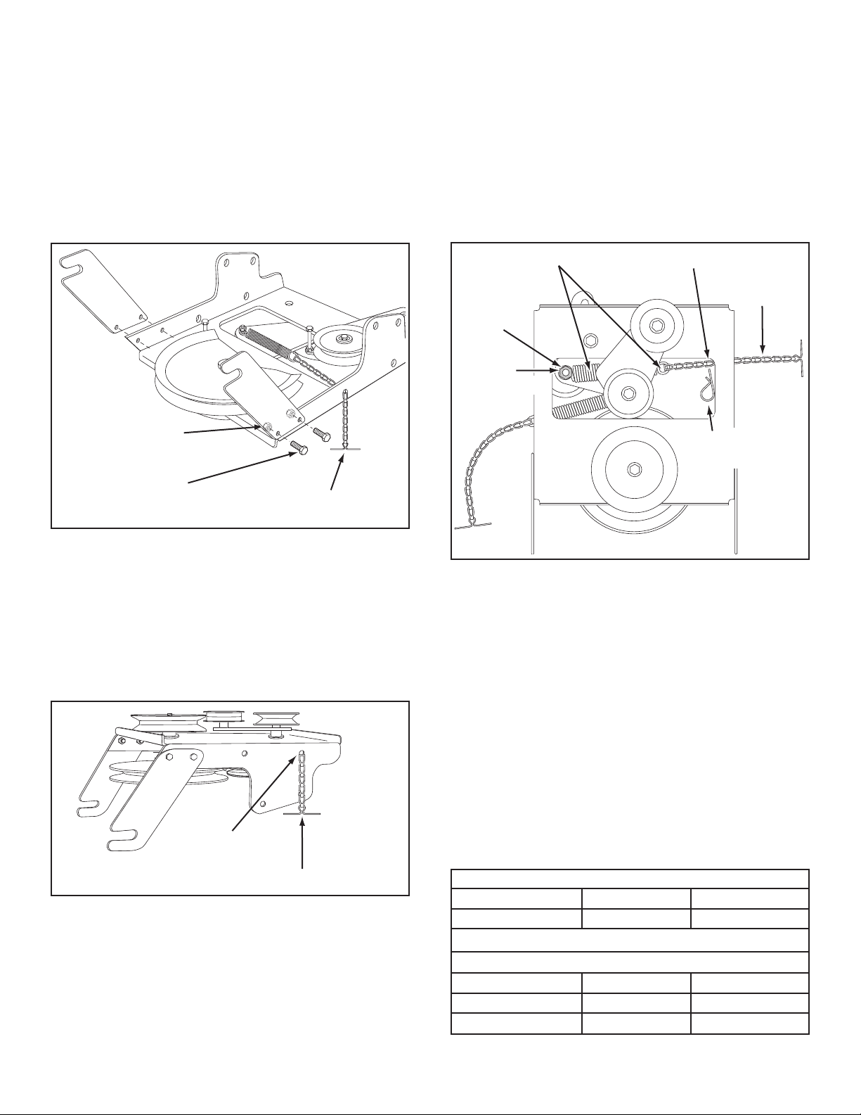
STEP 14: (SEE FIGURE 14)
• Attach the two suspension arms to the rear of the
clutch/idler assembly using two 5/16" x 3/4" hex bolts
(C) and 5/16" nylock nuts (Y) for each arm. Place the
arms on the outside of the frame with the notches to
the rear.
• Insert a tensioning chain through the hole shown and
attach the end link to the spring on the lower idler arm.
STEP 16: (SEE FIGURE 16)
• Hook one end of the spring supplied in the parts bag
through the end link of the tensioning chain.
• With the clutch/idler assembly turned upside down,
hook the other end of the spring onto the end of the
bolt and nut which secure the idler pulley to the upper
idler arm. Assemble a 3/8" hex lock nut (Z) onto the
bolt and nut, leaving enough gap between the nuts for
the spring to pivot freely.
• Attach a 3/32" hairpin cotter (FF) to the chain, placing
it in the fth link from the spring.
FIGURE 14
STEP 15: (SEE FIGURE 15)
• Turn the clutch/idler assembly upside down and insert
the second tensioning chain (JJ) through the left front
hole.
FIGURE 15
FIGURE 16 VIEW OF BOTTOM
SELECT THE CORRECT DRIVE BELT
(Electric clutch tractors with a single front deck
suspension bracket)
STEP 17: (SEE TABLE 1)
• Two different length drive belts are included with
your snow thrower. Use the table below to select
the correct drive belt for your type tractor. The part
number is printed on the outside of the belt .
• Set aside the belt that is not for your tractor to avoid
accidentally using it.
55" BELT (PART #46989)
TRACTOR TYPE DECK SIZE CLUTCH TYPE
(LT) Lawn Tractor 38", 42" Electric
56" BELT (PART #48138)
TRACTOR TYPE DECK SIZE CLUTCH TYPE
(LT) Lawn Tractor 48" Electric
(GT) Garden Tractor 48", 54" Electric
TABLE 1
12

PIVOT LOCK PIN (GG)
(use second hole)
SHOULDER
BOLT (M)
1/8" HAIRPIN
COTTER (EE)
L.H. HANGER
BRACKET
1/8" HAIRPIN
COTTER (EE)
ENGINE
PULLEY
ENGINE
PULLEY
KEEPER
BOLT
IDLER
PULLEY
CHAIN (JJ)
(L.H. SIDE)
STEP 18: (SEE FIGURE 17)
HEX BOLTS
DRIVE BELT
FLAT IDLER
PULLEY
• Turn the clutch/idler assembly right side up.
• Slightly loosen the hex bolt next to the at idler pulley.
Install the drive belt down between the hex bolt and the
at idler pulley with the at side of the belt against the
pulley. Retighten the hex bolt.
• Loop the belt around the large v-pulley, placing it
between the v-pulley and the hex bolt next to the pulley.
FIGURE 17
STEP 20: (SEE FIGURE 19)
• Assemble the drive belt onto the engine pulley rst
and then onto the large pulley on top of the clutch/
idler assembly. Place the belt to the inside of the idler
pulley and the belt keeper bolt located beside the
large pulley.
• Place tension on the belt by pulling the left side
tensioning chain (JJ) out as far as the 3/32" hairpin
cotter in the chain will allow. Secure the chain in this
position by inserting a 1/8" hairpin cotter (EE) through
the chain.
IMPORTANT: Do Not assemble the drive belt around the
outside of the keeper bolt beside the large pulley.
• Go to step 48 on page 22.
CLUTCH/IDLER ASSEMBLY
STOP
STEP 19: (SEE FIGURE 18)
• Attach the clutch/idler assembly to the tractor frame.
Hook the notched suspension arms onto the two
shoulder bolts (M) assembled to the outside of the
tractor frame. Lift the front of the assembly and attach
it to the R.H. and L.H. hanger brackets using two pivot
lock pins (GG) and 1/8" hairpin cotters (EE).
Did you choose the correct drive belt for
your tractor? Using the wrong length belt
may cause premature bearing or belt failure.
FIGURE 19 VIEWED FROM UNDERNEATH
FIGURE 18 VIEWED FROM LEFT SIDE
13
(3) 3/8" x 1"
THREAD FORMING
BOLTS (E)
5/16" FLANGED
NUT (W)
(SEE NOTE)
(3) 3/8" LOCK
WASHERS (O)
1/2" WASHER (R)
5/16" x 1"
CARRIAGE BOLT (J)
(SEE NOTE)
SUSPENSION
BRACKET
REMOVE BOLTS
IF PRESENT
FRONT
SUSPENSION
BRACKET
REPLACE BOLT
(IF PRESENT)
REMOVE BOLTS
(IF PRESENT)
INSTRUCTIONS FOR TRACTORS WITH DUAL
3/8" WASHER (T)
SHOULDER
BOLT (L)
3/8" FLANGED
NUT (X)
(3) 3/8" x 1"
THREAD FORMING
BOLTS (E)
(3) 3/8" LOCK
WASHERS (O)
3/8" FLANGED NUT (X)
(SEE NOTE)
(3) 1/2" WASHERS (R)
FRONT DECK SUSPENSION BRA CKETS
FASTEN SIDE PLATES TO TRACTOR
If your tractor resembles gure 20, go to step 21.
If your tractor resembles gure 22, go to step 23.
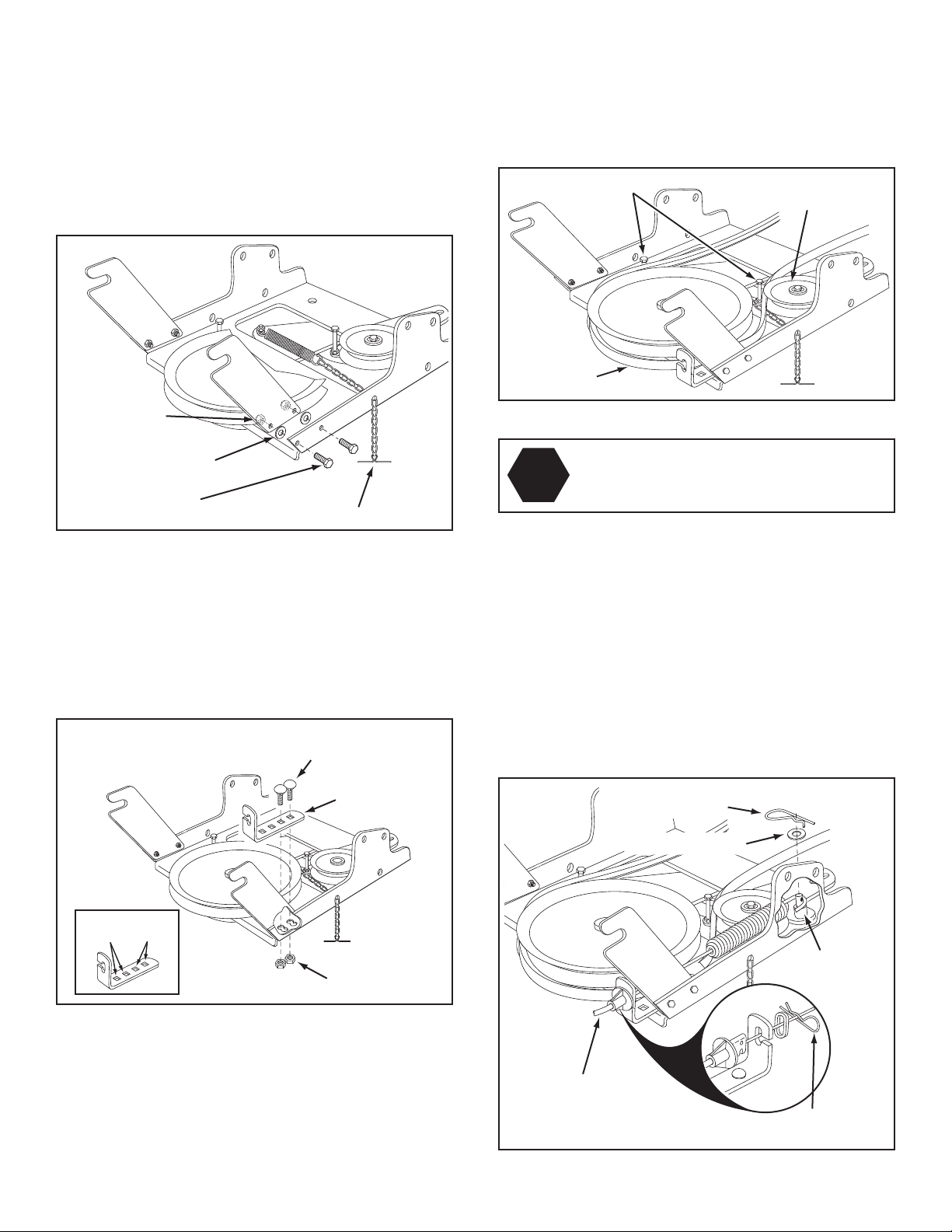
STEP 21: (SEE FIGURE 20)
Remove bolts from front three holes shown.
•
• If a bolt is present in the fourth hole, replace it with a
5/16" x 1" carriage bolt (J) without a nut. The bracket
fastened to inside of frame must remain in place.
STEP 23: (SEE FIGURE 22)
•
Remove any bolts found in the holes shown.
FIGURE 22 RIGHT SIDE VIEW
STEP 24: (SEE FIGURE 23)
• Fasten the R.H. Side Plate (bend facing out) to the
three holes shown in the tractor frame. Use three 3/8"
x 1" thread forming bolts (E), 3/8" lock washers (O)
and 1/2" washers (R). Use the 1/2" washers as shims
between the Side Plate and the tractor frame. Tighten
all bolts and repeat for the L.H. side.
NOTE: If the bolt inserts freely into the front hole, assemble
a 3/8" anged nut (X) onto the bolt.
FIGURE 20 RIGHT SIDE VIEW
STEP 22: (SEE FIGURE 21)
• Fasten the R.H. Side Plate (bend facing out) to the
front three holes shown in the tractor frame using
three 3/8" x 1" thread forming bolts (E), three 3/8"
lock washers (O) and one 1/2" washer (R) placed on
the third bolt as a shim between the side plate and
the frame. Tighten all bolts. Repeat for the L.H. side.
NOTE: If you installed a bolt in the fourth hole in step 21,
assemble a 5/16" ange nut (W) onto the bolt after the
side plate is installed.
• Go to step 25 on this page.
FIGURE 23 RIGHT SIDE VIEW
STEP 25: (SEE FIGURE 24)
Assemble a shoulder bolt (L) and a 3/8" washer (T) to
•
the outside of each side plate, securing them with a
3/8" anged nut (X).
FIGURE 21 RIGHT SIDE VIEW
FIGURE 24 RIGHT SIDE VIEW
14
INSTALLING HANGER BRACKETS
BOLT REMOVED
FROM THIS HOLE
SWAY BAR
BRACKET
SHOULDER BOLT (L)
3/8"
FLANGED
NUT (X)
3/8" x 1"
CARRIAGE
BOLT (G)
3/8" FLANGED
NUT (X)
L.H. HANGER
BRACKET
SUSPENSION ARM
SHOULDER BOLT (L)
3/8"
FLANGED
NUT (X)
R.H. HANGER BRACKET
BOLT REMOVED
FROM THIS HOLE
3/8" x 1"
CARRIAGE
BOLT (K)
3/8" FLANGED
NUT (X)
L.H. HANGER
BRACKET
SUSPENSION ARM
For better clearance, lower the tractor's suspension arms
using the attachment lift lever.
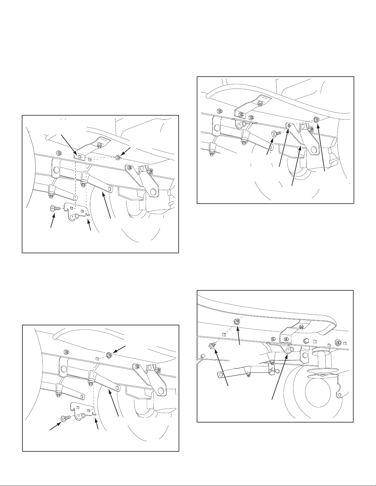
STEP 26: (SEE FIGURE 25 or 26)
On Tractors With Foot Rest Brackets
• Remove the bolt and nut that fasten the L.H. and R.H.
foot rest brackets to the frame.
• Attach the L.H. Hanger Bracket (marked "L") to the
inside of the tractor frame using two 3/8" x 1" carriage
bolts (G) and 3/8" anged nuts (X). Bolt heads go on
inside of tractor frame. Repeat for the R.H. side.
INSTALLING SHOULDER BOLTS
STEP 27: (SEE FIGURE 27)
• Remove the bolt, washer and nut which fasten the
sway bar bracket to the L.H. side of the tractor frame.
Replace with a shoulder bolt (L) and a 3/8" anged
nut (X). Bolt goes on inside of frame.
FIGURE 25 LEFT SIDE VIEW
On Tractors Without Foot Rest Brackets
• Find the empty hole beneath the foot rest. Attach the
L.H. Hanger Bracket (marked "L") to the inside of the
frame using a 3/8" x 1" carriage bolt (G) and a 3/8"
anged nut (X). Bolt head goes on inside of tractor
frame. Repeat for the R.H. side.
FIGURE 27 LEFT SIDE VIEW
STEP 28: (SEE FIGURE 28)
• Assemble a shoulder bolt (L) and 3/8" anged nut (X)
to the R.H. side of the tractor frame, using the rst
empty hole to the rear of the R.H. hanger bracket. Bolt
goes on inside of frame.
FIGURE 26 LEFT SIDE VIEW
FIGURE 28 RIGHT SIDE VIEW
15
INSTALLING CLUTCH/IDLER ASSEMBLY
ENGAGEMENT ROD
5/64" HAIRPIN
COTTER (DD)
TRACTOR'S CLUTCH ARM
SUSPENSION ARM
TRUNNION (CC)
REMOVE EXTENSION,
BOLT AND NUT
(IF PRESENT)
5/16" x 3/4"
HEX BOLT (C)
5/16" NYLOCK
NUT (Y)
TENSIONING CHAIN (JJ)
5/16" WASHER (Q)
HEX BOLTS
DRIVE BELT
FLAT IDLER
PULLEY
This section covers the installation of the Clutch/Idler
assembly to tractors with attachment clutches that are
either rod operated (p. 16), cable operated (p. 19) or
electric (p. 20). Use the appropriate instructions for your
tractor.
ROD OPERATED MANUAL ATTACHMENT CLUTCH
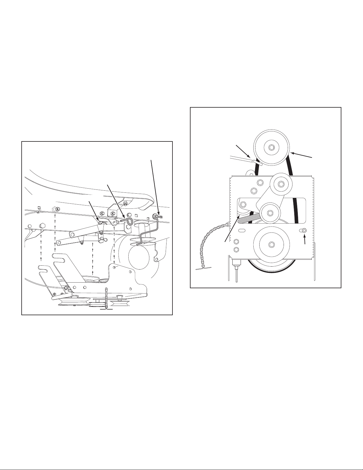
STEP 29: (SEE FIGURE 29)
• Move the attachment clutch lever on the dash panel to
the disengaged (down) position.
• Screw the trunnion (CC) onto the end of the snow
thrower engagement rod.
• Locate the clutch arm (where the mower clutch rod
was connected) underneath the right hand side the
tractor, just to the inside of the suspension arm. If
there is an extension attached to the clutch lever, the
extension, bolt and nut must be removed and stored
with the mower deck.
IMPORTANT: Re-attach the extension to the clutch
lever before reinstalling the mower deck.
• Position the engagement rod to the inside of the
clutch arm and insert the drilled end of the rod
through the arm. Secure with a 5/64" hairpin cotter
(DD).
FIGURE 30
STEP 31: (SEE FIGURE 31)
• Two different length drive belts are included with
your snow thrower. Tractors with manual attachment
clutches and dual front deck suspension brackets use
the 55" drive belt with #46989 printed on the outside
of the belt. DO NOT USE the other belt.
• Slightly loosen the hex bolt next to the at idler pulley.
Install the drive belt down between the hex bolt and the
at idler pulley with the at side of the belt against the
pulley. Retighten the hex bolt.
• Loop the belt around the large v-pulley, placing it
between the v-pulley and the hex bolt next to the pulley.
FIGURE 29 RIGHT SIDE VIEW
STEP 30: (SEE FIGURE 30)
• Attach the two suspension arms to the inside of the
clutch/idler assembly using two 5/16" x 3/4" hex bolts
(C), 5/16" washers (Q) and 5/16" nylock nuts (Y) for
each arm. Place the washers between the arms and
the assembly frame.
• Insert a tensioning chain through the hole shown and
attach the end link to the spring on the lower idler arm.
(#46989)
FIGURE 31
16
STOP
Did you choose the correct drive belt for
your tractor? Using the wrong length belt
may cause premature bearing or belt failure.
PIVOT LOCK PIN (GG)
(use second hole)
1/8" HAIRPIN COTTER (EE)
ENGAGEMENT
ROD
IDLER ARM
5/64" HAIRPIN
COTTER (DD)
TRUNNION (CC)
STOP BOLT
3/8" THIN
WASHER (S)
NEW ENGINE PULLEY KEEPER WITH
ORIGINAL BOLT, NUT AND WASHER
ENGINE
PULLEY
KEEPER BOLT
IDLER
PULLEY
ENGINE
PULLEY
KEEPER
Left Side
of Tractor
STEP 32: (SEE FIGURE 32)
• Be sure to lift up the front end of the engagement rod
as shown when performing the next operation. You
can temporarily support the rod using a rubber band
tied to the engine pulley keeper.
• Attach the clutch/idler assembly to the tractor frame
as follows. Hook the assembly's notched arms onto
the two shoulder bolts you assembled to the inside
of the tractor frame. Lift the front of the assembly and
attach it to the R.H. and L.H. hanger brackets using
two pivot lock pins (GG) and 1/8" hairpin cotters (EE).
FIGURE 33 RIGHT SIDE VIEW
STEP 34: (SEE FIGURE 34)
• Assemble the short "V" belt onto the engine pulley
and then onto the large pulley on top of the clutch/
idler assembly. The belt must be placed to the inside
of the engine pulley keeper, the idler pulley and the
keeper bolt located beside the large pulley.
FIGURE 32 RIGHT SIDE VIEW
STEP 33: (SEE FIGURE 33)
• Make sure the attachment clutch lever on the dash
panel is in the disengaged (down) position.
• Pivot the upper idler arm so that it rests against the
stop bolt and is pointing toward the front as shown.
Screw the trunnion (CC) along the threads of the
engagement rod until it is aligned at the front end of
the idler arm slot. Attach the trunnion (CC) to the slot
using the 3/8" thin washer (S) and a 5/64" hairpin
cotter (DD).
• Remove the engine pulley keeper from the side of
the tractor frame by removing the washer and nut
that secure the keeper. Attach the new pulley keeper
supplied with the snow thrower, reusing the original
bolt, washer and nut.
NOTE: Some tractors may already be equipped with a
pulley keeper that is identical to the new one supplied.
IMPORTANT: Do Not assemble the "V" belt around the
outside of the engine pulley keeper or the keeper bolt.
• Go to step 48 on page 22.
CLUTCH/IDLER ASSEMBLY
FIGURE 34 VIEWED FROM UNDERNEATH
17
CABLE
BRACKET
5/16" x 3/4"
CARRIAGE BOLT (K)
5/16" NYLOCK
NUT (Y)
42"
DECKS
46"
DECKS
TRACTOR'S
CLUTCH CABLE
5/64" HAIR
COTTER PIN (DD)
1/4" WASHER (P)
SPACER (LL)
5/64" HAIR
COTTER PIN (DD)
5/16" x 3/4"
HEX BOLT (C)
5/16" NYLOCK
NUT (Y)
TENSIONING CHAIN (JJ)
5/16" WASHER (Q)
CABLE OPERATED MANUAL ATTACHMENT CLUTCH
HEX BOLTS
DRIVE BELT
FLAT IDLER
PULLEY
STEP 35: (SEE FIGURE 35)
• Attach the two suspension arms to the rear of the
clutch/idler assembly using two 5/16" x 3/4" hex bolts
(C), 5/16" washer (Q) and 5/16" nylock nuts (Y) for
each arm. Place the arms on the outside of the frame
with the notches to the rear.
• Insert a tensioning chain through the hole shown and
attach the end link to the spring on the lower idler arm.
• Slightly loosen the hex bolt next to the at idler pulley.
Install the drive belt down between the hex bolt and the
at idler pulley with the at side of the belt against the
pulley. Retighten the hex bolt.
• Loop the belt around the large v-pulley, placing it
between the v-pulley and the hex bolt next to the pulley.
(#46989)
FIGURE 37
Did you choose the correct drive belt for
STOP
your tractor? Using the wrong length belt
may cause premature bearing or belt failure.
FIGURE 35
STEP 36: (SEE FIGURE 36)
• Assemble the cable bracket to the clutch/idler
assembly using two 5/16" x 3/4" carriage bolts (K) and
5/16" nylock nuts (Y). Use the two front holes in the
cable bracket if your tractor has a 42" mower deck.
Use the two rear holes if your tractor has a 46" mower
deck.
STEP 38: (SEE FIGURE 38)
• Move the attachment clutch lever on the dash panel to
the disengaged (down) position.
• Place the clutch/idler assembly on the oor on the right
side of the tractor.
• Attach the tractor's clutch cable to the cable bracket.
Secure the cable housing guide (groove down) to the
cable bracket using the original collar and a 5/64" hair
cotter pin (DD).
• Place a spacer (LL) on the welded pin on the idler arm.
Hook the end of the clutch spring over the pin and
secure it with a 1/4" washer (P) and a 5/64" hair cotter
pin (DD).
FIGURE 36
STEP 37: (SEE FIGURE 37)
• Two different length drive belts are included with
your snow thrower. Tractors with manual attachment
clutches and dual front deck suspension brackets use
the 55" drive belt with #46989 printed on the outside
of the belt. DO NOT USE the other belt.
FIGURE 38
18
STEP 39: (SEE FIGURE 39)
NEW ENGINE PULLEY KEEPER WITH
ORIGINAL BOLT, NUT AND WASHER
PIVOT LOCK PIN (GG)
(use second hole)
1/8" HAIRPIN COTTER (EE)
ENGINE
PULLEY
KEEPER BOLT
IDLER
PULLEY
ENGINE
PULLEY
KEEPER
Left Side
of Tractor
• Remove the engine pulley keeper from the side of
the tractor frame by removing the washer and nut
that secure the keeper. Attach the new pulley keeper
supplied with the snow thrower, reusing the original
bolt, washer and nut.
NOTE: Some tractors may already be equipped with a
pulley keeper that is identical to the new one supplied.
STEP 40: (SEE FIGURE 40)
• Assemble the short "V" belt onto the engine pulley
and then onto the large pulley on top of the clutch/idler
assembly. The belt must be placed to the inside of the
engine pulley keeper, the idler pulley and the keeper
bolt located beside the large pulley.
IMPORTANT: Do Not assemble the "V" belt around the
outside of the engine pulley keeper or the keeper bolt.
• Attach the clutch/idler assembly to the tractor frame
as follows. Hook the assembly's notched arms onto
the two shoulder bolts you assembled to the inside
of the tractor frame. Lift the front of the assembly and
attach it to the R.H. and L.H. hanger brackets using
two pivot lock pins (GG) and 1/8" hairpin cotters (EE).
• Go to step 48 on page 22.
CLUTCH/IDLER ASSEMBLY
FIGURE 39
FIGURE 40 VIEWED FROM UNDERNEATH
19
ELECTRIC ATTACHMENT CLUTCHES
TENSIONING CHAIN (JJ)
LEFT FRONT HOLE
CHAIN
(L.H. SIDE)
3/32" HAIR
COTTER PIN (FF)
5TH LINK
LEFT
SIDE
3/8" HEX
LOCK NUT (Z)
SPRING
RIGHT
SIDE
ATTACH
SPRING
HERE
5/16" x 3/4"
HEX BOLT (C)
5/16" NYLOCK
NUT (Y)
TENSIONING CHAIN (JJ)
5/16" WASHER (Q)
STEP 41: (SEE FIGURE 41)
• Attach the two suspension arms to the rear of the
clutch/idler assembly using two 5/16" x 3/4" hex bolts
(C), 5/16" washer (Q) and 5/16" nylock nuts (Y) for
each arm. Place the arms on the outside of the frame
with the notches to the rear.
• Insert a tensioning chain through the hole shown and
attach the end link to the spring on the lower idler arm.
STEP 43: (SEE FIGURE 43)
• Hook the spring from the parts bag through the end of
the tensioning chain.
• Hook the other end of the spring onto the bottom of
the bolt and nut which secure the idler pulley to the
upper idler arm. Hold the bolt head and assemble a
3/8" hex lock nut (Z) onto the bolt, leaving enough
space for the spring to pivot freely between the two
nuts.
• Attach a 3/32" hairpin cotter (FF) to the chain, placing
it in the fth link from the spring.
FIGURE 41
STEP 42: (SEE FIGURE 42)
• Pace the extra tensioning chain (JJ) through the left
front hole in the clutch/idler assembly and then turn
the assembly upside down.
FIGURE 42
FIGURE 43 VIEW OF BOTTOM
STEP 44: (SEE TABLE 2)
• Two different length drive belts are included with
your snow thrower. Use the table below to select
the correct drive belt for your type tractor. The part
number is printed on the outside of the belt .
• Set aside the belt that is not for your tractor to avoid
accidentally using it.
55" BELT (PART #46989)
TRACTOR TYPE DECK SIZE CLUTCH TYPE
(LT) Lawn Tractor 38", 42", 46" Electric
56" BELT (PART #48138)
TRACTOR TYPE DECK SIZE CLUTCH TYPE
(LT) Lawn Tractor 48" Electric
TABLE 2
20
1/8" HAIRPIN
COTTER (EE)
ENGINE
PULLEY
ENGINE
PULLEY
Left Side
of Tractor
KEEPER
BOLT
IDLER
PULLEY
PIVOT LOCK PIN (GG)
(use second hole)
1/8" HAIRPIN COTTER (EE)
HEX BOLTS
DRIVE BELT
FLAT IDLER
PULLEY
STEP 45: (SEE FIGURE 44)
• Turn the clutch/idler assembly right side up.
• Slightly loosen the hex bolt next to the at idler pulley.
Install the drive belt down between the hex bolt and the
at idler pulley with the at side of the belt against the
pulley. Retighten the hex bolt.
• Loop the belt around the large v-pulley, placing it
between the v-pulley and the hex bolt next to the pulley.
Place the belt to the inside of the other at idler pulley.
FIGURE 44
STEP 47: (SEE FIGURE 46)
• Assemble the drive belt onto the engine pulley and
then onto the large pulley on top of the clutch/idler
assembly. The belt must be placed to the inside of
the idler pulley and the keeper bolt located beside the
large pulley.
• Place tension on the belt by pulling the left side
tensioning chain out as far as the 3/32" hairpin cotter
(FF) will allow. Secure the chain in this position by
inserting a 1/8" hairpin cotter (EE) through the chain.
IMPORTANT: Do Not assemble the "V" belt around the
outside of the engine pulley keeper or the keeper bolt.
CLUTCH/IDLER ASSEMBLY
Did you choose the correct drive belt for
STOP
your tractor? Using the wrong length belt
may cause premature bearing or belt failure.
STEP 46: (SEE FIGURE 45)
• Attach the clutch/idler assembly to the tractor frame
as follows. Hook the assembly's notched arms onto
the two shoulder bolts you assembled to the inside
of the tractor frame. Lift the front of the assembly and
attach it to the R.H. and L.H. hanger brackets using
two pivot lock pins (GG) and 1/8" hairpin cotters (EE).
FIGURE 46 VIEWED FROM UNDERNEATH
FIGURE 45 RIGHT SIDE VIEW
21
LIFT RELEASE
CABLE
HEX NUT
LOCK
WASHER
HEX NUT
CABLE
WIRE
LIFT
ROD
TRIGGER
ASSEMBLY
5/16" NYLOCK NUT (Y)
5/16" x 1-3/4"
HEX BOLT (B)
ASSEMBLY OF THE SNOW THROWER
CHUTE CRANK ROD
CRANK SUPPORT TUBE
TILT CONTROL HANDLE
5/16" x 1-3/4"
CARRIAGE BOLT (H)
BOWED WASHER (U)
5/16" NYLOCK NUT (Y)
TILT
CONTROL
ASSEMBLY
5/16" NYLOCK NUT (Y)
5/16" x 1-1/4"
CARRIAGE BOLT (I)
CRANK ROD
SUPPORT TUBE
DISCHARGE
HOUSING
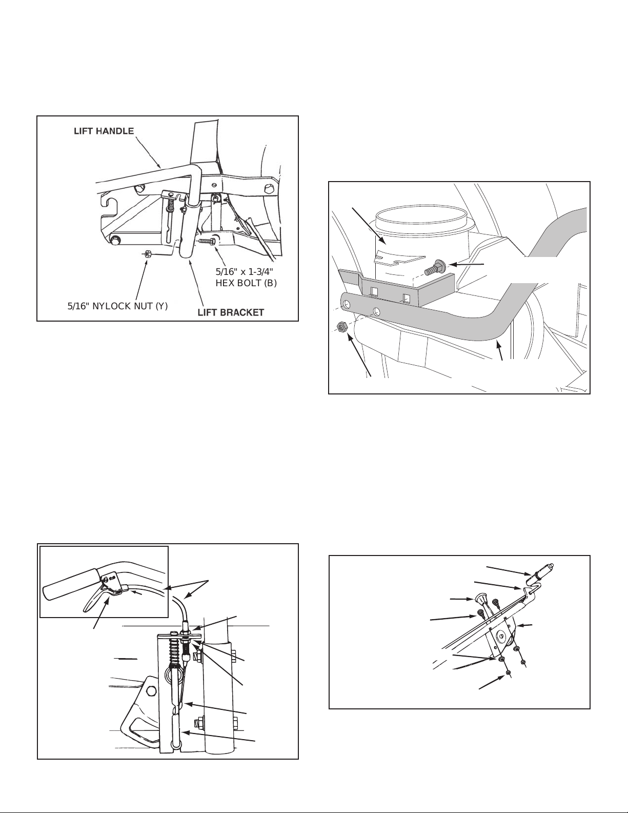
STEP 48: (SEE FIGURE 47)
• Place the lift handle into the lift bracket on the right side
of the snow thrower. Fasten the handle to the bracket
using two 5/16" x 1-3/4" hex bolts (B) and 5/16" Nylock
nuts (Y).
FIGURE 47 RIGHT SIDE VIEW
STEP 50: (SEE FIGURE 49)
• Tilt the snow thrower back down to the ground.
• Remove the nylon tie which fastens the auger
drive belt to the discharge housing, leaving the belt
assembled around the pulleys.
• Remove the nylon tie which fastens the chute crank
rod to the crank rod support tube.
• Assemble the crank rod support tube to the bracket
on the left side of the discharge housing using two
5/16" x 1-1/4" carriage bolts (I), and 5/16" Nylock nuts
(Y).
NOTE: Be sure the lift release cable's plastic covering
stays inserted into the trigger assembly for the next step.
STEP 49: (SEE FIGURE 48)
• Push the lift handle down into the locked position.
HINT: For easier assembly of the lift release cable, tilt the
snow thrower forward onto the spiral auger.
Insert the end of the cable wire into the hole in the
lift rod. Place the threaded tting into the slot in the
lift bracket, with one hex nut above and one hex nut
and the lock washer below the slot. Tighten the nuts,
adjusting them to eliminate slack in the cable wire.
Refer also to the Service and Adjustments section on
page 28 in this manual.
FIGURE 49 LEFT SIDE VIEW
STEP 51: (SEE FIGURE 50)
• Attach the chute tilt control assembly to the top side
of the crank support tube using two 5/16" x 1-3/4"
carriage bolts (H), bowed washers (U) and 5/16"
Nylock nuts (Y).
FIGURE 48 RIGHT SIDE VIEW
FIGURE 50 LEFT SIDE VIEW
22
5/16" NYLOCK NUT (Y)
CHUTE CRANK
BRACKET
5/16" WASHER (Q)
CHUTE
CRANK
ROD
ROD
SUPPORT
BRACKET
5/16" x 1"
CARRIAGE BOLT (J)
SPIRAL
CHUTE KEEPER (BB)
ANTI-ROTATION
BRACKET
1/4" FLANGED
LOCK NUT (V)
1/4" FLAT
WASHER (P)
1/4" x 1"
HEX BOLT (D)
PLASTIC CAP (HH)
GREASED
SURFACE
FLANGE
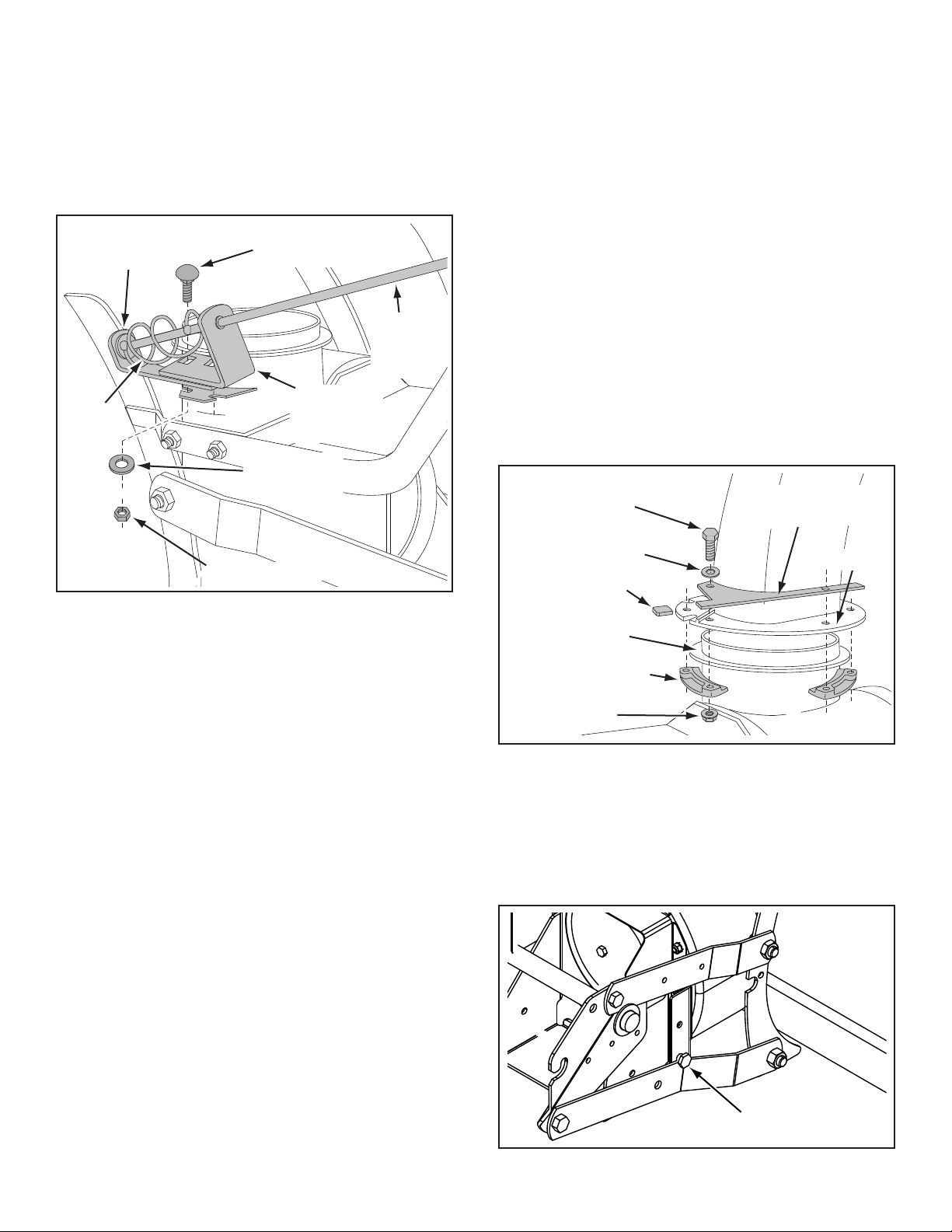
STEP 52: (SEE FIGURE 51)
STOP BOLT
• Attach the chute crank rod assembly brackets to
the plastic bracket on the left side of the discharge
housing. Align the chute crank bracket beneath the
rod support bracket and assemble both to the plastic
bracket using two 5/16" x 1" carriage bolts (J), 5/16"
washers (Q) and 5/16" Nylock nuts (Y). Do not
tighten yet.
STEP 53: (SEE FIGURE 52)
• Coat the top of the ring around the discharge opening
with general purpose grease.
• Place the discharge chute (facing forward) onto the
ring. Place the anti-rotation bracket on top of the chute
ange, aligning it with the holes on the right hand side
of the ange. Attach the three chute keepers (BB)
(right side up as shown) to the bottom of the ange
using six 1/4" x 1" hex bolts (D), 1/4" at washers (P)
and 1/4" anged lock nuts (V). Tighten carefully so
that the nuts are snug but do not dig into the plastic
chute keepers.
• Place the plastic cap (HH) onto the short end of the
anti-rotation bracket.
• Position the crank rod spiral (see gure 51) so that it
does not rub against the bottoms of the notches in the
chute ange. Tighten the nuts.
• Check if the crank rod rotates the chute freely. If not,
loosen by 1/4 turn each of the six hex bolts holding
the chute keepers to the chute ange.
• Secure the control cables to the crank rod support
tube using a nylon tie (II).
FIGURE 51 LEFT SIDE VIEW
FIGURE 52 RIGHT SIDE VIEW
STEP 54: (SEE FIGURE 53)
Skip this step if you have a lawn tractor.
This step is for garden tractors only.
• If you have a (GT) Garden Tractor, remove the stop
bolts from each side of the snow thrower frame.
FIGURE 53 RIGHT SIDE VIEW
23
ATTACHING SNOW THROWER TO TRACTOR
IDLER
PULLEY
AUGER PULLEY
TWIST
1/4 TURN
TWIST
1/4 TURN
IDLER
PULLEY
ATTACHMENT PIN
(After installing auger belt)
1/8" HAIRPIN
COTTER (EE)
SHOULDER
BOLT
MOUNTING
PLATE
SIDE PLATE
IDLER
ARM
REAR
PULLEY
LEFT SIDE
OF
TRACTOR
NOTE: An additional person's help may be required to
mount the snow thrower to the front of the tractor.
STEP 55: (SEE FIGURE 54)
• Place the tractor and snow thrower on a at, level
surface so that the tractor can be rolled forward to
attach the snow thrower.
• Remove the Attachment Pin from the snow thrower.
• Extend the auger belt out behind the snow thrower,
making sure the belt is still looped over the top of
the large drive pulley and underneath the two idler
pulleys. The "V" side of the belt must be seated in the
grooves of all three pulleys.
• Roll the tractor up behind the snow thrower, centering
it between the snow thrower's mounting plates.
• Raise the rear of the snow thrower by lifting up on
the lift handle until the notches in the mounting plates
align with the shoulder bolts in the tractor's side
plates. Guide the bolts into the notches.
• To ease the assembly of the auger drive belt, delay
the installation of the attachment pin until you have
assembled the belt as instructed in steps 56 and 57.
BEFORE INSTALLING THE AUGER BELT
STEP 56: (SEE FIGURE 55)
• The auger belt comes preassembled to the pulleys on
the snow thrower housing. Make sure the belt passes
over the top of the auger pulley and then twists 1/4
turn to pass underneath each side idler pulley. The
"V" side of the belt must mate with the grooves of the
pulleys.
FIGURE 55
FIGURE 54 RIGHT SIDE VIEW
INSTALLING THE AUGER BELT
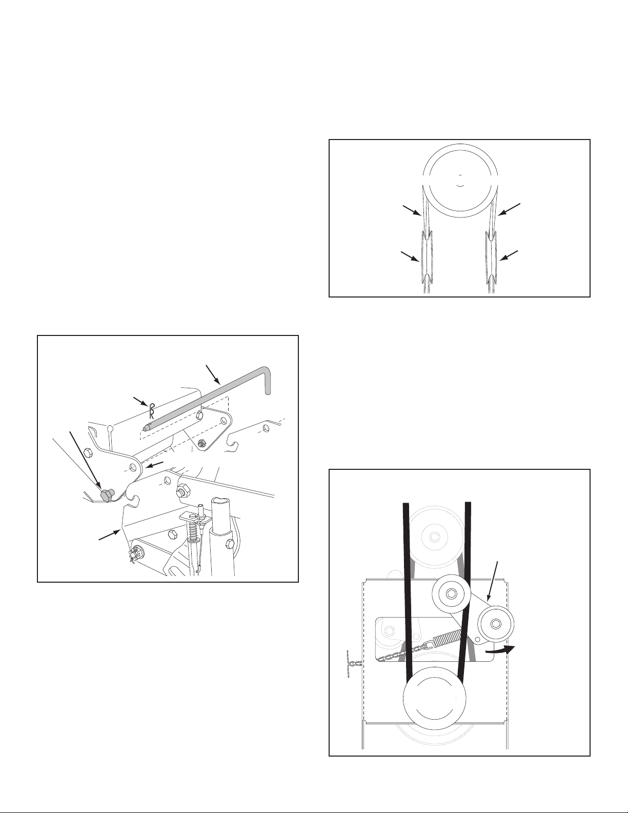
STEP 57: (SEE FIGURE 56)
• Push the lift handle down to increase slack in the belt
(attachment pin must rst be removed).
• Swing the idler arm over to the left side.
• Place the auger belt around the rear pulley and
between the two pulleys on the idler arm. The "V" side
of the belt must be seated in the grooves of the v-
pulleys.
CLUTCH/IDLER ASSEMBLY
FIGURE 56 VIEWED FROM UNDERNEATH
24
 Loading...