

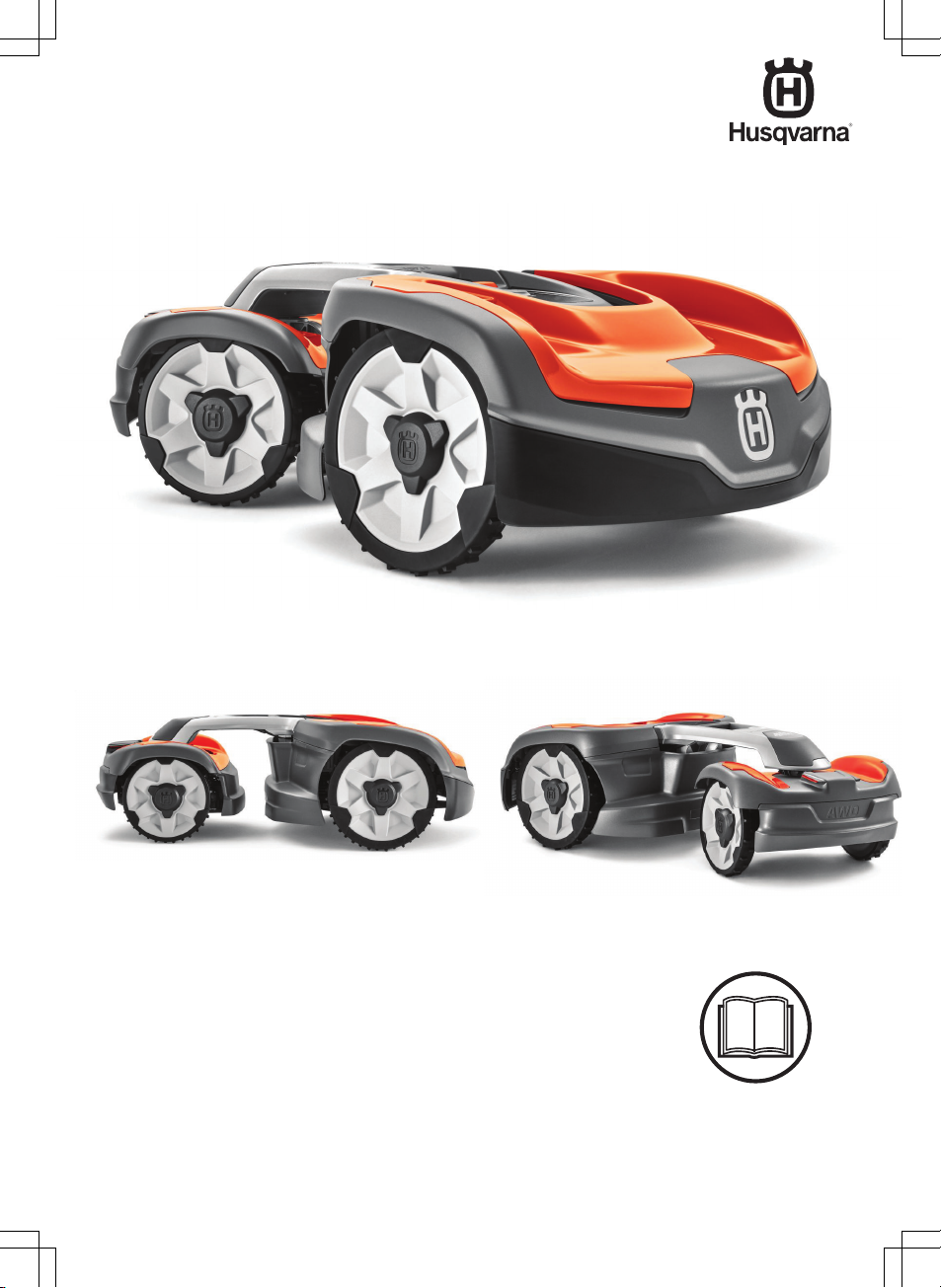
EN, English
Operator's manual
HUSQVARNA AUTOMOWER
®
535 AWD
Read the operator's manual carefully and make sure that you
understand the instructions before you use the product.

Contents
1 Introduction
1.1 Support.......................................................3
1.2 Product description.....................................3
1.3 Automower® Connect.................................3
1.4 Product overview .......................................4
1.5 Symbols on the product..............................5
1.6 Symbols on the battery...............................6
1.7 General safety instructions.........................6
2 Safety
2.1 IMPORTANT. READ CAREFULLY
BEFORE USE. KEEP FOR FUTURE
REFERENCE................................................. 11
2.2 Safety definitions...................................... 12
2.3 Safety instructions for operation...............12
3 Installation
3.1 Introduction - Installation.......................... 16
3.2 Main components for installation..............16
3.3 General preparations................................16
3.4 Before the installation of the wires........... 16
3.5 Installation of the product......................... 21
3.6 To put the wire into position with stakes...24
3.7 To bury the boundary wire or the
guide wire....................................................... 24
3.8 To extend the boundary wire or the
guide wire....................................................... 24
3.9 After the installation of the product...........25
3.10 Automower® Connect.............................25
3.11 To start the product for the first time...... 26
3.12 Settings in Automower® Connect...........27
4 Operation
4.1 To switch on the product.......................... 32
4.2 Operating modes......................................32
4.3 To stop the product.................................. 33
4.4 To switch off the product.......................... 33
4.5 To charge the battery............................... 33
4.6 To adjust the cutting height with
Automower® Connect.....................................33
5 Maintenance
5.1 Introduction - maintenance.......................35
5.2 Clean the product..................................... 35
5.3 Replace the blades...................................36
5.4 To replace the top covers.........................37
5.5 Battery...................................................... 39
5.6 Winter service...........................................39
6 Troubleshooting
6.1 Introduction - troubleshooting...................41
6.2 Fault messages........................................ 41
6.3 Information messages.............................. 48
6.4 Indicator lamp in the charging station.......49
6.5 Symptoms................................................ 50
6.6 Find breaks in the loop wire..................... 51
7 Transportation, storage and disposal
7.1 Transportation.......................................... 54
7.2 Storage.....................................................54
7.3 Disposal....................................................54
8 Technical data
8.1 Technical data.......................................... 56
8.2 Registered trademarks............................. 58
9 Warranty
9.1 Warranty terms.........................................59
10 EC Declaration of Conformity
10.1 EC Declaration of Conformity.................60
2 1427 - 002 - 20.12.2019
1 Introduction
Serial number:
PIN code:
The serial number is on the product rating plate and on the product carton.
• Use the serial number to register your product on www.husqvarna.com.
1.1 Support
For support about the product, speak to your
Husqvarna servicing dealer.
1.2 Product description
Note: Husqvarna regularly updates the
appearance and function of the products. Refer
to
Support on page 3
.
The product is a robotic lawn mower. The product
has a battery power source and cuts the grass
automatically. It continuously alternates between
mowing and charging. The movement pattern is
random, which means that the lawn is mowed
evenly and with less wear. The boundary wire
and the guide wire controls the movement of the
product within the work area. Sensors in the
product senses when it is approaching the
boundary wire. The front of the product always
passes the boundary wire by a specific distance
before the product turns around. When the
product hits an obstacle or approaches the
boundary wire the product selects a new
direction.
The operator selects the operation settings in
Automower® Connect app. The app shows the
selected and possible operation settings, and the
operation mode of the product.
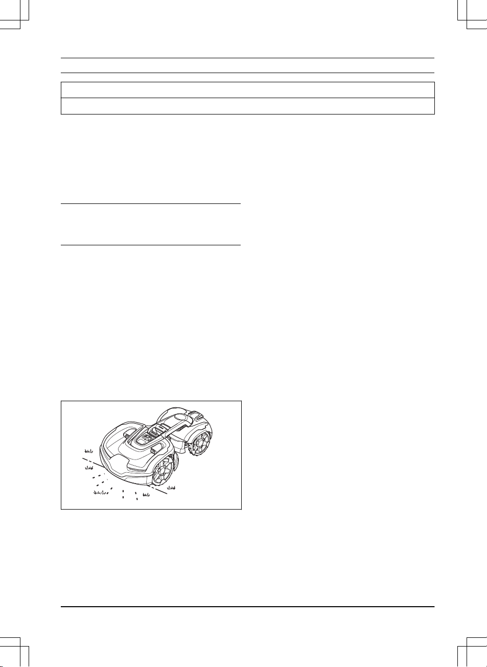
1.2.1 Mowing technique
The product is emission free, easy to use and
saves energy. The frequent cutting technique
improves the grass quality and decreases the
use of fertilizers. Collection of grass is not
necessary.
1.2.2 Find the charging station
The product operates until the battery is low, then
it starts to go to the charging station. The product
has 3 search methods to find the charging
station. Refer to
To find the charging station on
page 28
.
1.3 Automower® Connect
Automower® Connect is a mobile application that
makes it possible to select the operation settings
remotely. Refer to
Automower® Connect on page
25
.
1427 - 002 - 20.12.2019 Introduction - 3
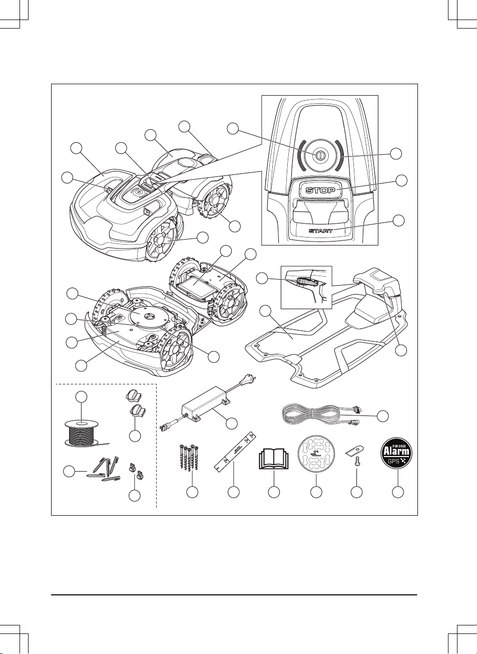
1.4 Product overview
2
4
17
7
8
9
12
3
21
18
16
14
15
22
23
28 2926
25
27
24
32
30
33
31
6
1
10
11
5
13
19
20
1. Ultrasonic sensors
2. Front top cover
3. Lifting handle
4. Rear top cover
5. Charging plates
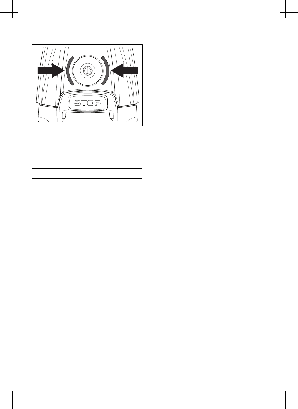
6. On/Off-button
7. LED status indicator
8. STOP button
4 - Introduction
1427 - 002 - 20.12.2019
9. START button
10. Front wheels
11. Rear wheels
12. Battery cover
13. Rear chassis box with electronics, motors
and battery
14. LED for operation check of the charging
station and boundary wire
15. Charging station
16. Contact strips
17. Skid plate
18. Blades
19. Front chassis box with electronics and
motors
20. Rating plate (incl. product identification
code)
21. Blade disc
22. Power supply (the appearance of the power
supply may differ depending on market)
23. Low voltage cable
24. Screws for securing the charging station
25. Measurement gauge for help when installing
the boundary wire (the measurement gauge
is broken loose from the box)
26. Operator’s Manual and Quick Guide
27. Cable markers
28. Extra blades
29. Alarm decal
30. Loop wire for boundary loop and guide wire
1
31. Couplers for loop wire
2
32. Stakes
3
33. Connector for the loop wire
4
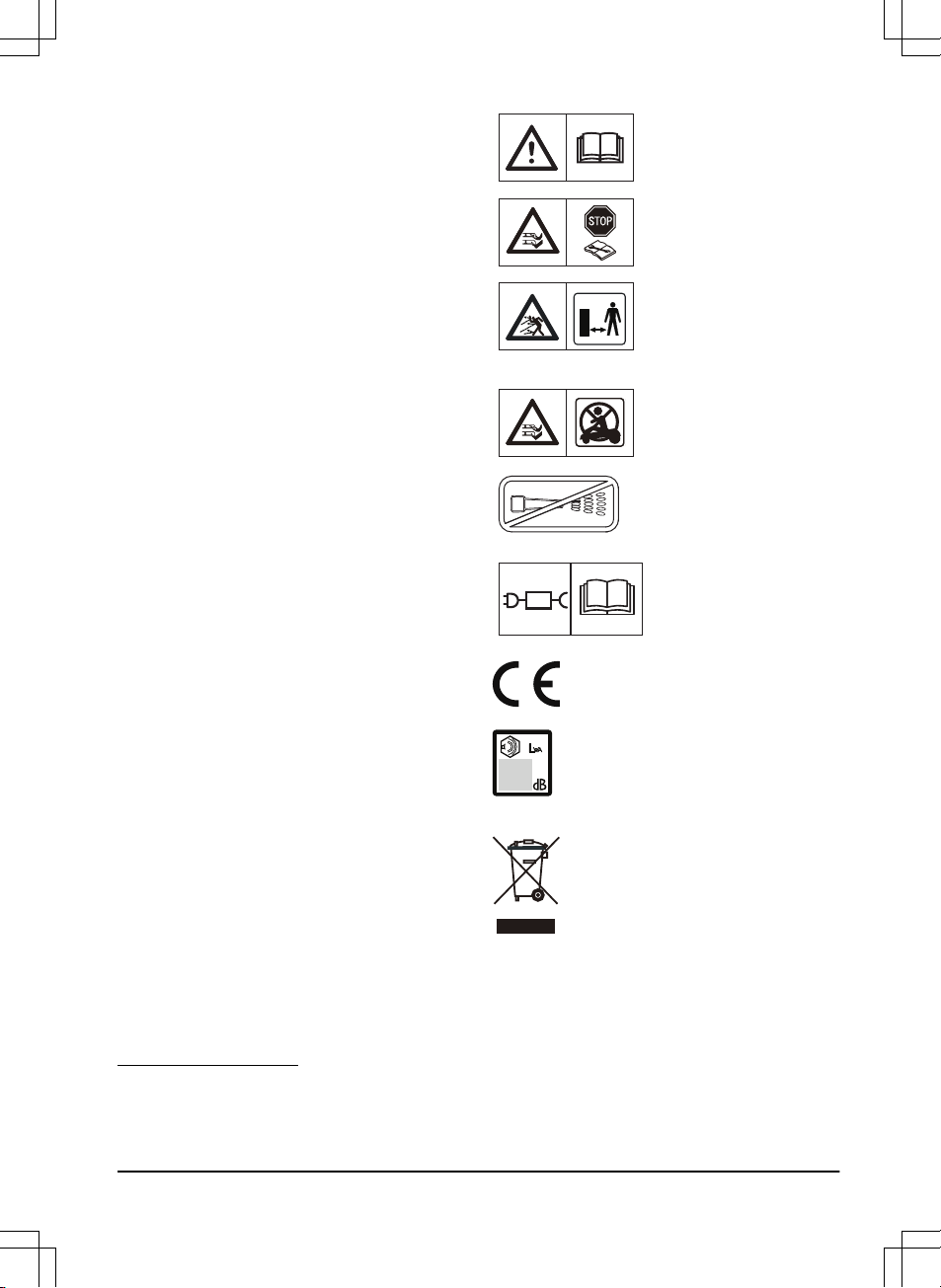
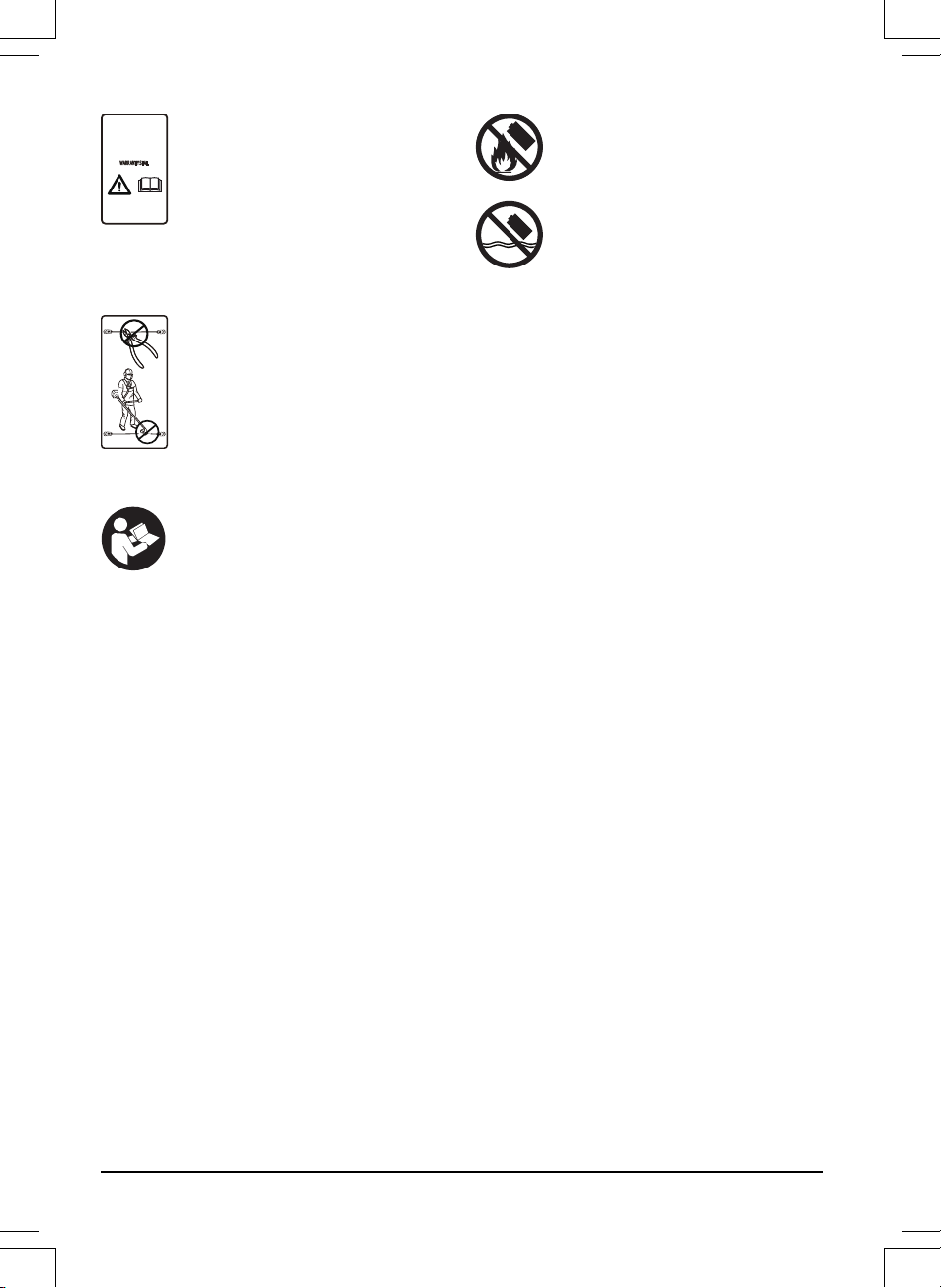
1.5 Symbols on the product
These symbols can be found on the product.
Study them carefully.
WARNING: Read the
user instructions before
operating the product.
WARNING: Disable the
product before working on
or lifting the product.
WARNING: Keep a safe
distance from the product
when operating. Keep
your hands and feet away
from the rotating blades.
WARNING: Do not ride
on the product. Never put
your hands or feet close
to or under the product.
Never use a high-pressure washer or even running water to clean the
product.
Use a detachable power
supply as defined on the
rating label next to the
symbol.
This product conforms to the
applicable EC Directives.
Noise emission to surroundings. The
product’s emissions are set out in
Technical data on page 56
and on the
rating plate.
It is not permitted to dispose this
product as normal household waste.
Ensure that the product is recycled in
accordance with local legal
requirements.
1
Is a part of the Installation kit which is purchased separately.
2
Refer to note 1
3
Refer to note 1
4
Refer to note 1
1427 - 002 - 20.12.2019
Introduction - 5
The chassis contains components
which are sensitive to electrostatic
discharge (ESD). The chassis must
also be resealed in a professional
manner. For these reasons the chassis
shall only be opened by authorized
service technicians. A broken seal can
result in the entire or parts of the
warranty no longer being valid.
The low voltage cable must not be
shortened, extended or spliced.
Do not use a trimmer nearby the low
voltage cable. Be careful when
trimming edges where the cables are
placed.
1.6 Symbols on the battery
Read the user instructions.
Do not discard the battery into fire and
do not expose the battery to a heat
source.
Do not immerse the battery into water.
1.7 General safety instructions
The following system is used in the Operator’s
Manual to make it easier to use:
• Text written in
italics
is a text that is shown
in the Automower® Connect app or is a
reference to another section in the
Operator’s Manual.
• Text written in bold is one of the buttons on
the product.
• Text written in
UPPERCASE
and
italics
refer
to the different operating modes available in
the product.
6 - Introduction 1427 - 002 - 20.12.2019
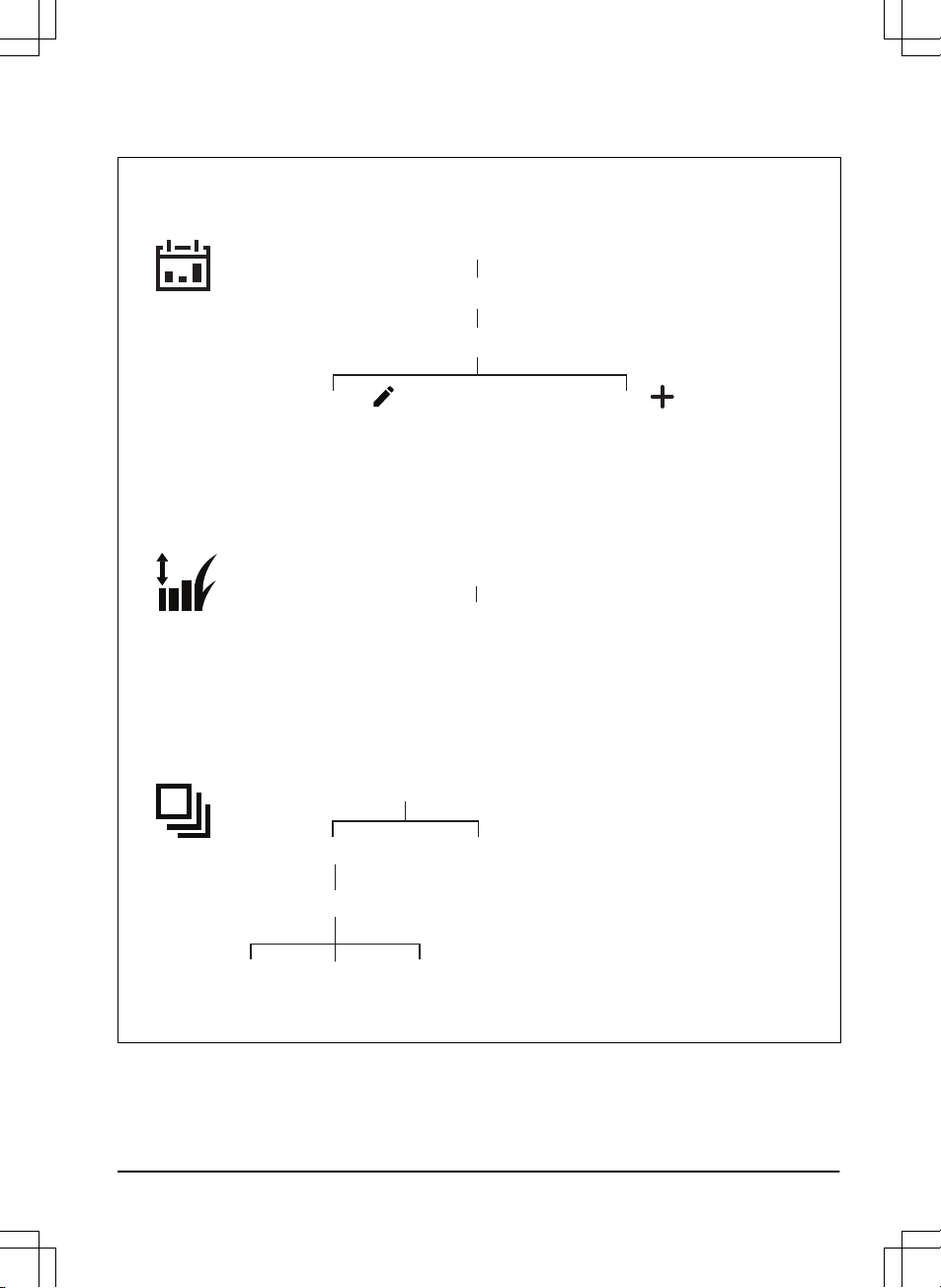
1.7.1 Menu structure overview 1
Operation
Cutting time
Low
High
Weather timer
Schedule
Edit
Overview Schedule settings
Cutting height
Cutting height
Change current
Schedule settings
Add new
Schedule settings
ECO mode
Medium
1427 - 002 - 20.12.2019 Introduction - 7
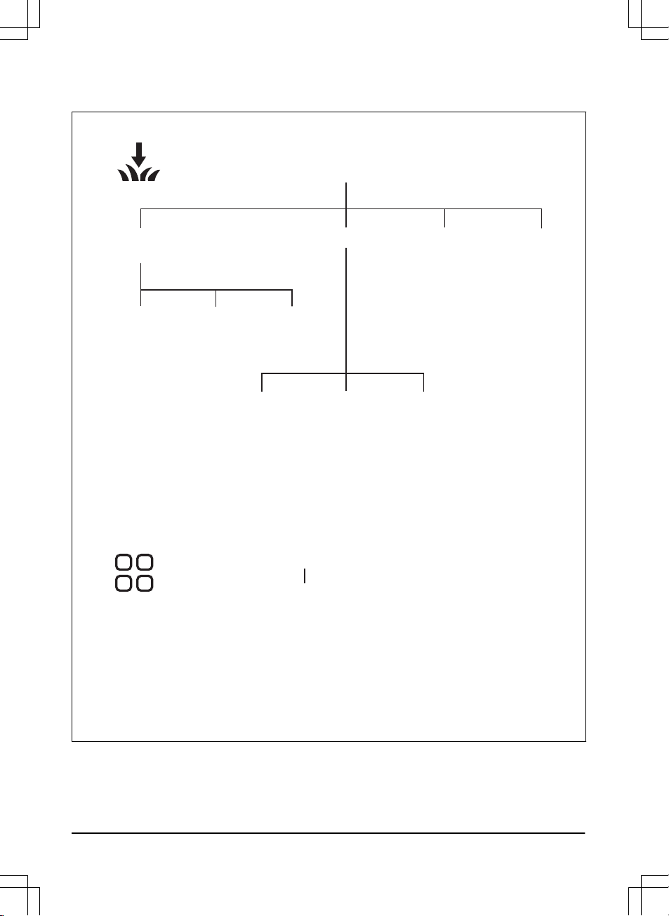
1.7.2 Menu structure overview 2
Installation
Find
charging station
Drive
past wire
Lawn coverage
Charging
station signal
Follow
boundary wire
Follow guide
1/2/3
GPS assisted
navigation (default)
Area
1/2/3/4/5
How often
Accessories
Mower house
Starting
point
8 - Introduction 1427 - 002 - 20.12.2019
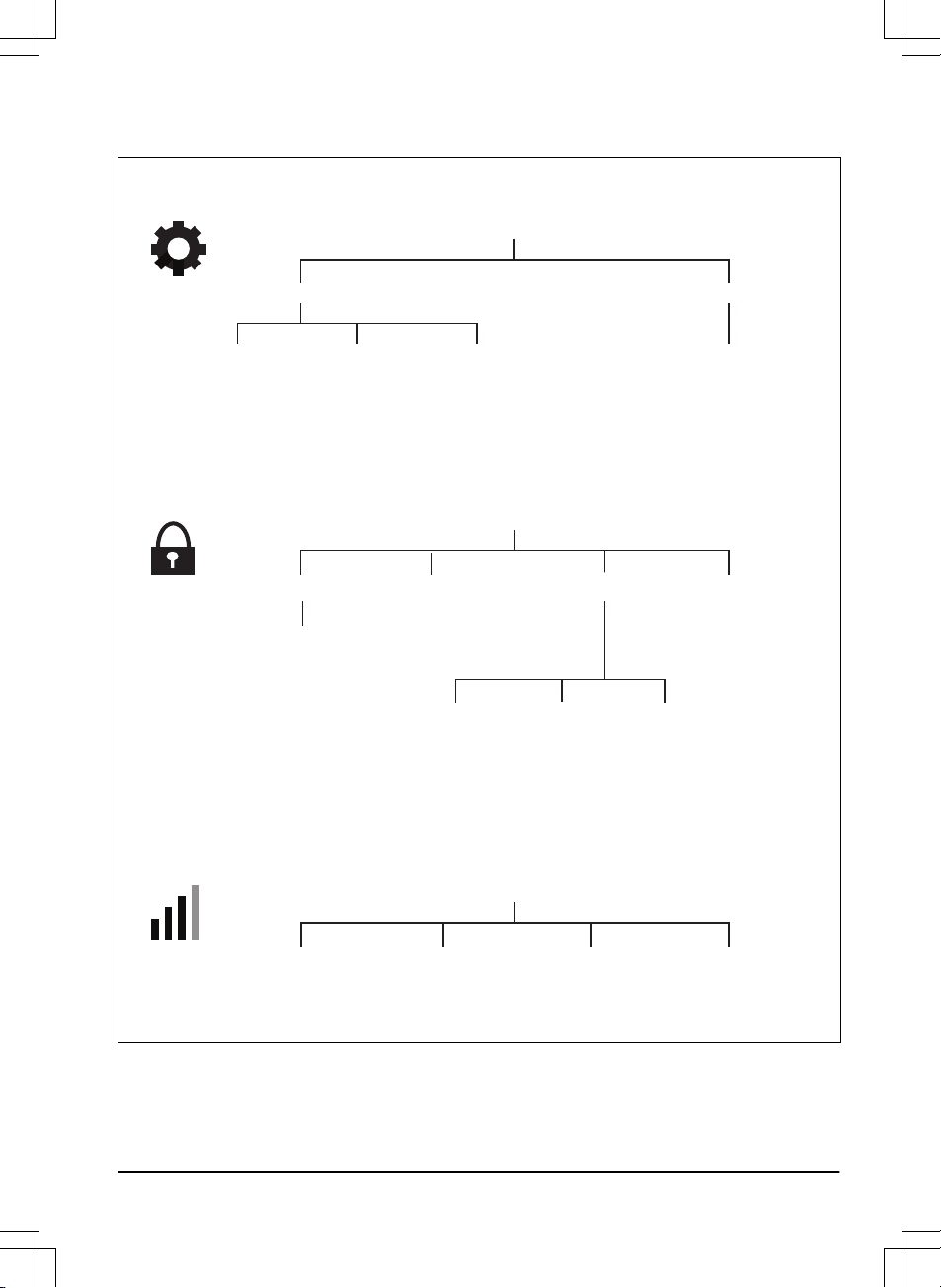
1.7.3 Menu structure overview 3
General
Security
Create new
loop signal
New loop signal
GeoFenceChange PIN code Theft protection
Alarm
duration
STOP button
pressed
Carried
away
Time & date Reset to factory settings
Mower time
(Edit)
Mower date
(Edit)
Time & date
from phone
Reset to factory settings
Initiate
new pairing
Automower® Connect
Connected
/Not connected
Remove mower
from paired accounts
Signal strength
/No signal
1427 - 002 - 20.12.2019 Introduction - 9
1.7.4 LED status indicator
LED indication Status
Green In operation
Blue Parked
Red Error
Yellow Paused/stopped
Flashing yellow PIN code needed
Pulsating green/blue Charging in progress
Flashing green/blue Push the ON/OFF button
to confirm start of operation
Flashing green, lowfrequent
Inactive
White Switching off
10 - Introduction 1427 - 002 - 20.12.2019

2 Safety
2.1 IMPORTANT. READ CAREFULLY
BEFORE USE. KEEP FOR FUTURE
REFERENCE
The operator is responsible for accidents or hazards occurring to
other people or property.
This appliance is not intended for use by persons (including
children) with reduced physical, sensory or mental capabilities (that
could affect a safe handling of the product), or lack of experience
and knowledge, unless they have been given supervision or
instruction concerning use of the appliance by a person
responsible for their safety.
This appliance can be used by children aged from 8 years and
above and persons with reduced physical, sensory or mental
capabilities or lack of experience and knowledge if they have been
given supervision or instruction concerning use of the appliance in
a safe way and understand the hazards involved. Local regulations
may restrict the age of the operator. Cleaning and maintenance
shall not be made by children without supervision.
Never connect the power supply to an outlet if the plug or cord is
damaged. Worn or damaged cord increase the risk of electric
shock.
Only charge the battery in the included charging station. Incorrect
use may result in electric shock, overheating or leaking of
corrosive liquid from the battery. In the event of leakage of
electrolyte, flush with water/neutralizing agent. Seek medical help if
it comes in contact with the eyes.
Use only original batteries recommended by the manufacturer.
Product safety cannot be guaranteed with other than original
batteries. Do not use non-rechargeable batteries.
The appliance must be disconnected from the supply mains when
removing the battery.
1427 - 002 - 20.12.2019
Safety - 11
WARNING: The product
can be dangerous if used
incorrectly.
WARNING: Do not use
the product when
persons, especially
children, or animals, are
in the work area.
WARNING: Keep your
hands and feet away
from the rotating blades.
Never put your hands or
feet close to or under the
product when the motor
is running.
WARNING: In the event
of an injury or accident
seek medical help.
2.2 Safety definitions
Warnings, cautions and notes are used to point
out specially important parts of the manual.
WARNING:
Used if there is a risk of
injury or death for the operator or
bystanders if the instructions in the
manual are not obeyed.
CAUTION: Used if there is a risk of
damage to the product, other materials
or the adjacent area if the instructions
in the manual are not obeyed.
Note: Used to give more information that is
necessary in a given situation.
2.3 Safety instructions for operation
2.3.1 Use
• The product may only be used with the
equipment recommended by the
manufacturer. All other types of use are
incorrect. The manufacturer’s instructions
with regard to operation/maintenance must
be followed precisely.
• The product may only be operated,
maintained and repaired by persons that are
fully conversant with its special
characteristics and safety regulations.
Please read the Operator’s Manual carefully
and make sure you understand the
instructions before using the product.
• It is not permitted to modify the original
design of the product. All modifications are
made at your own risk.
• Warning signs shall be placed around the
work area of the product if it is used in public
areas. The signs shall have the following
text: Warning! Automatic lawn mower! Keep
away from the machine! Supervise children!
WARNING!
Automatic lawnmower!
Keep away from the machine!
Supervise children!
I am a robotic lawnmower and I work here quietly
to keep the lawn in perfect condition.
I work 24/7 independently of weather conditions and do it
without releasing any exhaust emissions.
Stay a while and enjoy my work,
but please let me work in peace.
12
- Safety
1427 - 002 - 20.12.2019
• Use the park function or switch off the
product when persons, especially children or
pets, are in the work area. Refer to
To
switch off the product on page 33
. It is
recommended to program the product for
use during hours when the area is free from
activity, e.g. at night. Consider that certain
species, e.g. hedgehogs, are active at night.
They can potentially be harmed by the
product. Refer to
Schedule on page 27
.
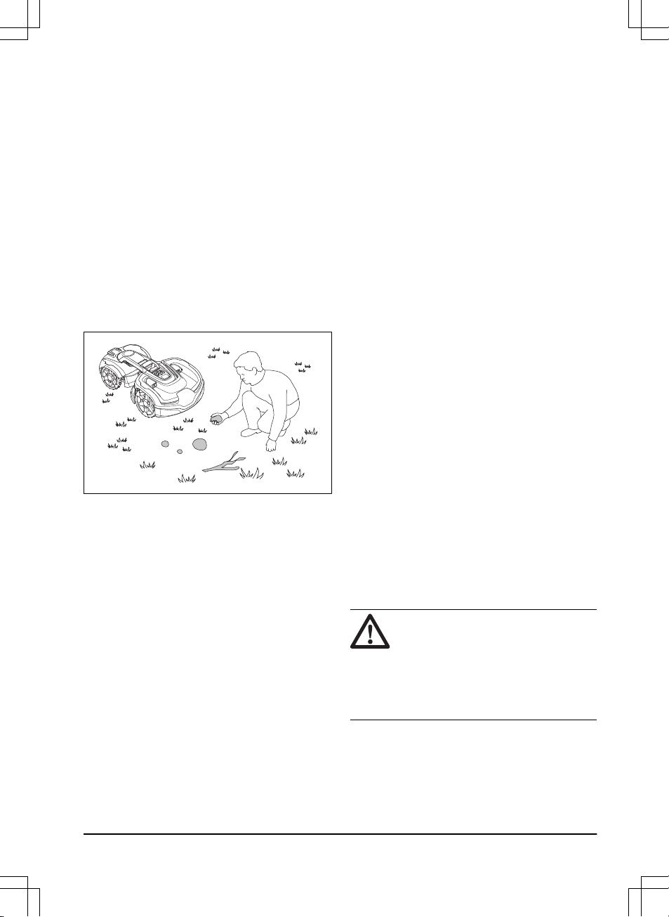
• Check that there are no foreign objects such
as stones, branches, tools or toys on the
lawn. If the blades hit foreign objects the
blades can be damaged. Always switch off
the product before clearing a blockage.
Inspect the product for damage before
staring the product again. Refer to
To switch
off the product on page 33
.
• If the product starts to vibrate abnormally.
Always switch off the product and inspect for
damage before staring the product again.
Refer
To switch off the product on page 33
.
• Switch on the product according to the
instructions. When the product is switched
on; make sure to keep your hands and feet
away from the rotating blades. Never put
your hands and feet under the product.
• Never touch moving hazardous parts, such
as the blade disc, before it has come to a
complete stop.
• Never lift up the product or carry it around
when it is switched on.
• The product must never be allowed to
collide with persons or other living creatures.
If a person or other living creature comes in
the way of the product, it shall be stopped
immediately. Refer to
To stop the product on
page 33
.
• Do not put anything on top of the product or
its charging station.
• Do not allow the product to be used with a
defective guard, blade disc or body. Neither
should it be used with defective blades,
screws, nuts or cables. Never connect a
damaged cable, or touch a damaged cable
before it is disconnected from the supply.
• Do not use the product if the STOP button
does not work.
• Always switch off the product when it is not
in use. The product can only start when the
correct PIN code has been entered.
• The product must never be used at the
same time as a sprinkler. Use the
Schedule
function so the product and sprinkler never
run simultaneously. Refer to
Schedule on
page 27
.
• Husqvarna does not guarantee full
compatibility between the product and other
types of wireless systems such as remote
controls, radio transmitters, hearing loops,
underground electric animal fencing or
similar.
• The built-in alarm is very loud. Be careful,
especially if the product is handled indoors.
• Metal objects in the ground (for example
reinforced concrete or anti-mole nets) can
result in a stoppage. The metal objects can
cause interference with the loop signal
which then can lead to a stoppage.
• Operation and storage temperature is 0-50
°C / 32-122 °F. Temperature range for
charging is 0-45 °C / 32-113 °F. Too high
temperatures might cause damage to the
product.
2.3.2 Battery safety
WARNING:
Lithium-ion batteries can
explode or cause fire if disassembled,
short-circuited, exposed to water, fire,
or high temperatures. Handle carefully,
do not dismantle, open the battery or
use any type of electrical/mechanical
abuse. Avoid storage in direct sunlight.
For more information about the battery, refer to
Battery on page 39
1427 - 002 - 20.12.2019
Safety - 13
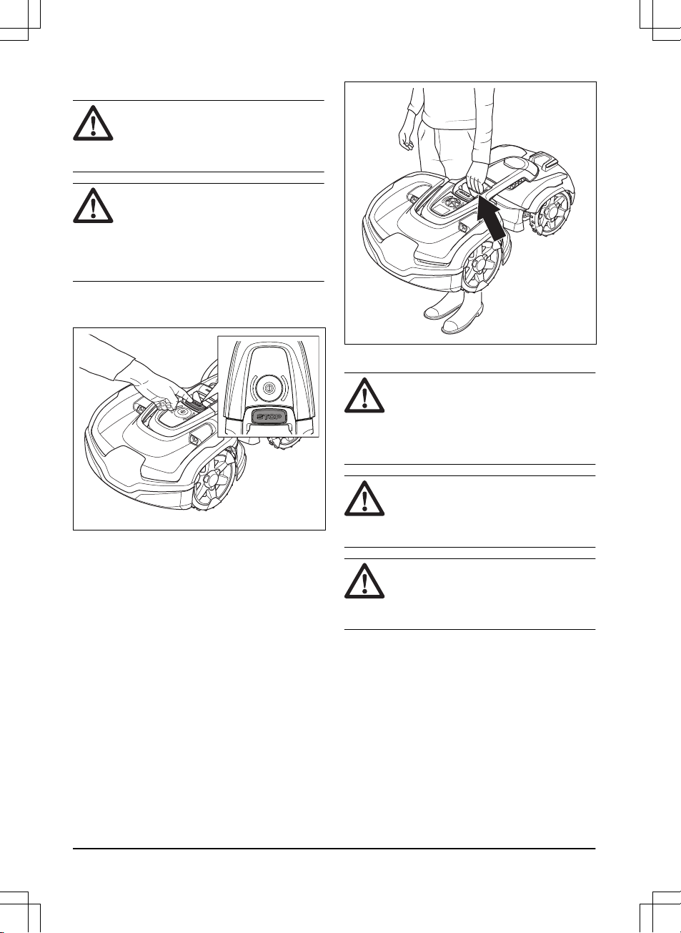
2.3.3 How to lift and move the product
WARNING: The product must be
switched off before you lift it. The
product is switched off when the LED
status indicator is not lit.
CAUTION: Do not lift the product when
it is parked in the charging station. It
can damage the charging station
and/or the product. Push the STOP
button and pull the product out of the
charging station before lifting it.
To safely move from or within the work area:
1. Push the STOP button to stop the product.
2. Enter the PIN code if required.
3. Push the ON/OFF button for 3 seconds to
switch off the product.
4. Make sure that the LED status indicator is
not lit.
5. Carry the product by the lifting handle.
2.3.4 Maintenance
WARNING: The product must be
switched off before it is turned upside
down.
The product must be switched off
before any maintenance is done.
CAUTION: Never use a high-pressure
washer or even running water to clean
the product. Never use solvents for
cleaning.
WARNING: Use the plug to disconnect
the charging station before any
cleaning or maintenance of the
charging station or the loop wire.
Inspect the product each week and replace any
damaged or worn parts. Refer to
Maintenance on
page 35
.
14
- Safety
1427 - 002 - 20.12.2019
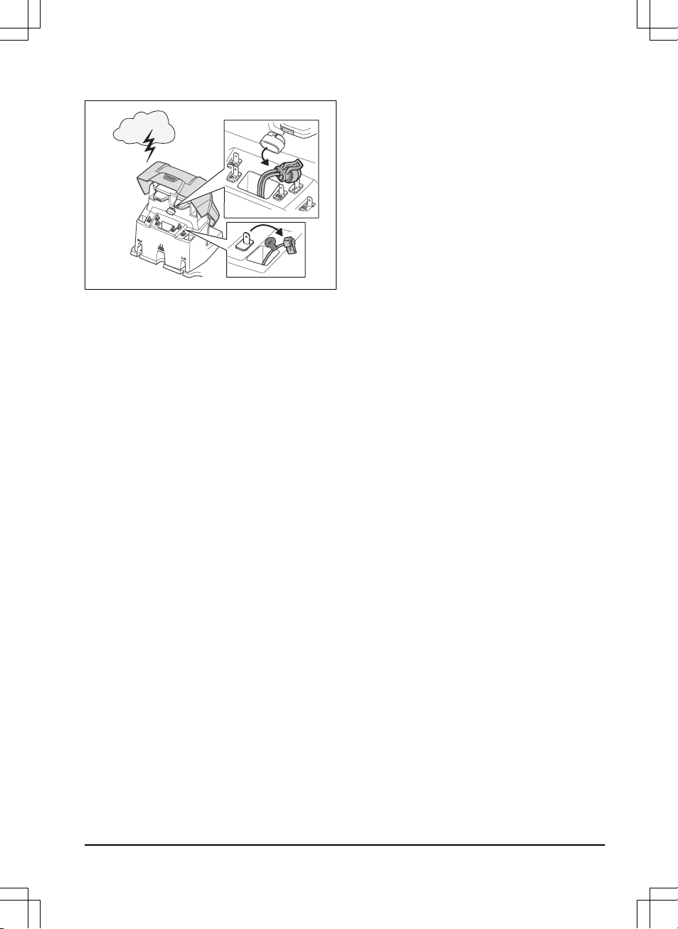
2.3.5 In the event of a thunderstorm
To reduce the risk of damage to electrical
components in the product and the charging
station, we recommend that all connections to the
charging station are disconnected (power supply,
boundary wire and guide wire) if there is a risk of
a thunderstorm.
1. Mark the wires to simplify reconnecting. The
charging station’s connections are marked
AR, AL and G1, G2, G3.
2. Disconnect all connected wires and the
power supply.
3. Connect all the wires and the power supply
if there is no longer a risk of thunder. It is
important that each wire is connected to the
right place.
1427 - 002 - 20.12.2019
Safety - 15
3 Installation
3.1 Introduction - Installation
WARNING: Read and understand the
safety chapter before you install the
product.
CAUTION: Use original spare parts
and installation material.
Note: Refer to www.husqvarna.com for more
information about installation.
3.2 Main components for installation
The installation involves the following
components:
• A robotic lawn mower that mows the lawn
automatically.
• A charging station, which has 3 functions:
• To send control signals along the
boundary wire.
• To send control signals along the guide
wire so that the product can be send to
specific remote areas in the garden and
can find its way back to the charging
station.
• To charge the product.
• A power supply, which is connected to the
charging station and a 100-240V wall
socket.
• Loop wire, which is laid around the work
area and around objects and plants that the
product must not run into. The loop wire is
used both as boundary wire and guide wire.
3.3 General preparations
CAUTION:
Holes with water in the
lawn can cause damage to the
product.
Note: Read through the Installation chapter
before beginning the installation. How the
installation is done affects how the product
performs. It is therefore important to plan the
installation carefully.
• Make a blueprint of the work area and
include all obstacles. This makes it easier to
see the ideal positions for the charging
station, the boundary wire and the guide
wire.
• Make a mark on the blueprint where to put
the charging station, the boundary wire and
the guide wire.
• Make a mark on the blueprint where the
guide wire connects to the boundary wire.
Refer to
To install the guide wire on page
23
.
• Fill in holes in the lawn.
• Cut the grass before you install the product.
Make sure that the grass is maximum 10
cm / 4 in.
Note: The first weeks after installation the
perceived sound level when cutting the grass
may be higher than expected. When the product
has cut the grass for some time, the perceived
sound level is much lower.
3.4 Before the installation of the wires
You can select to attach the wires with stakes or
bury them. You can use the 2 procedures for the
same work area.
• Bury the boundary wire or the guide wire if
you are going to use a dethatcher on the
work area. If not, attach the boundary wire
or guide wire with stakes.
3.4.1 To examine where to put the charging
station
• Keep a minimum 3 m / 10 ft. of free space in
front of the charging station.
• Keep a minimum of 1.5 m / 5 ft. of free
space to the right and to the left of the
charging station.
• Put the charging station near a power outlet.
• Put the charging station on a level surface.
16
- Installation
1427 - 002 - 20.12.2019
max. 5 cm / 2"
max. 5 cm / 2"
• Put the charging station in the largest open
section of the work area.
• Put the charging station in an area without
an irrigation system.
• Put the charging station in an area with
protection from the sun.
• If the charging station is installed on an
island, make sure to connect the guide wire
to the island. Refer to
To make an island on
page 19
.
3.4.2 To examine where to put the power
supply
WARNING:
Do not cut or extend the
low-voltage cable. There is a risk of
electrical shock.
CAUTION: Make sure that the blades
on the product do not cut the lowvoltage cable.
CAUTION: Do not put the low-voltage
cable in a coil or below the charging
station plate. The coil causes
interference with the signal from the
charging station.
• Put the power supply in an area with a roof
and protection from the sun and rain.
• Put the power supply in an area with good
airflow.
• Use a residual-current device (RCD) when
you connect the power supply to the power
outlet.
Low-voltage cables of different lengths are
available as accessories.
3.4.3 To examine where to put the
boundary wire
CAUTION: If the work area is adjacent
to water bodies, slopes, precipices or a
public road, the boundary wire must
have a protective wall. The wall must
be minimum 15 cm / 6 in. in height.
CAUTION: Do not let the product
operate on gravel.
CAUTION: Do not make sharp bends
when you install the boundary wire.
CAUTION: For careful operation
without noise, isolate all obstacles
such as trees, roots and stones.
The boundary wire should be put as a loop
around the work area. Sensors in the product
senses when the product approaches the
boundary wire, and the product selects another
direction.
To make the connection easier between the
guide wire and the boundary wire, it is
recommended to make an eyelet where the guide
wire will be connected. Make the eyelet with
approximately 20 cm / 8 in. of the boundary wire.
1427 - 002 - 20.12.2019
Installation - 17
Note: Make a blueprint of the work area before
you install the boundary wire and guide wire.
D
E
B
C
F
A
• Put the boundary wire around all of the work
area (A). Adapt the distance between the
boundary wire and obstacles.
• Put the boundary wire 35 cm / 14 in. (B)
from an obstacle that is more than 5 cm / 2
in. high.
35 cm /14
"
> 5 cm / 2
"
• Put the boundary wire 30 cm / 12 in. (C)
from an obstacle that is 1-5 cm / 0.4-2 in.
high.
1-5 cm / 0.4 - 2"
30 cm / 12"
• Put the boundary wire 10 cm / 4 in. (D) from
an obstacle that is less than 1 cm / 0.4 in.
10 cm / 4"
max 1 cm / 0.4"
• If you have a paving stone path that is in
level with the lawn, put the boundary wire
below the paving stone.
Note:
If the paving stone is minimum 30 cm /
12 in. wide, use the factory setting for the
Drive Past Wire
function to cut all the grass
adjacent to the paving stone. Refer to
Drive
Past Wire on page 29
.
• If you make an island, put the boundary wire
that runs to and from the island near
together (E). Put the wires in the same
stake. Refer to
To make an island on page
19
.
18
- Installation
1427 - 002 - 20.12.2019
• Make an eyelet (F) where the guide wire is
to be connected to the boundary wire.
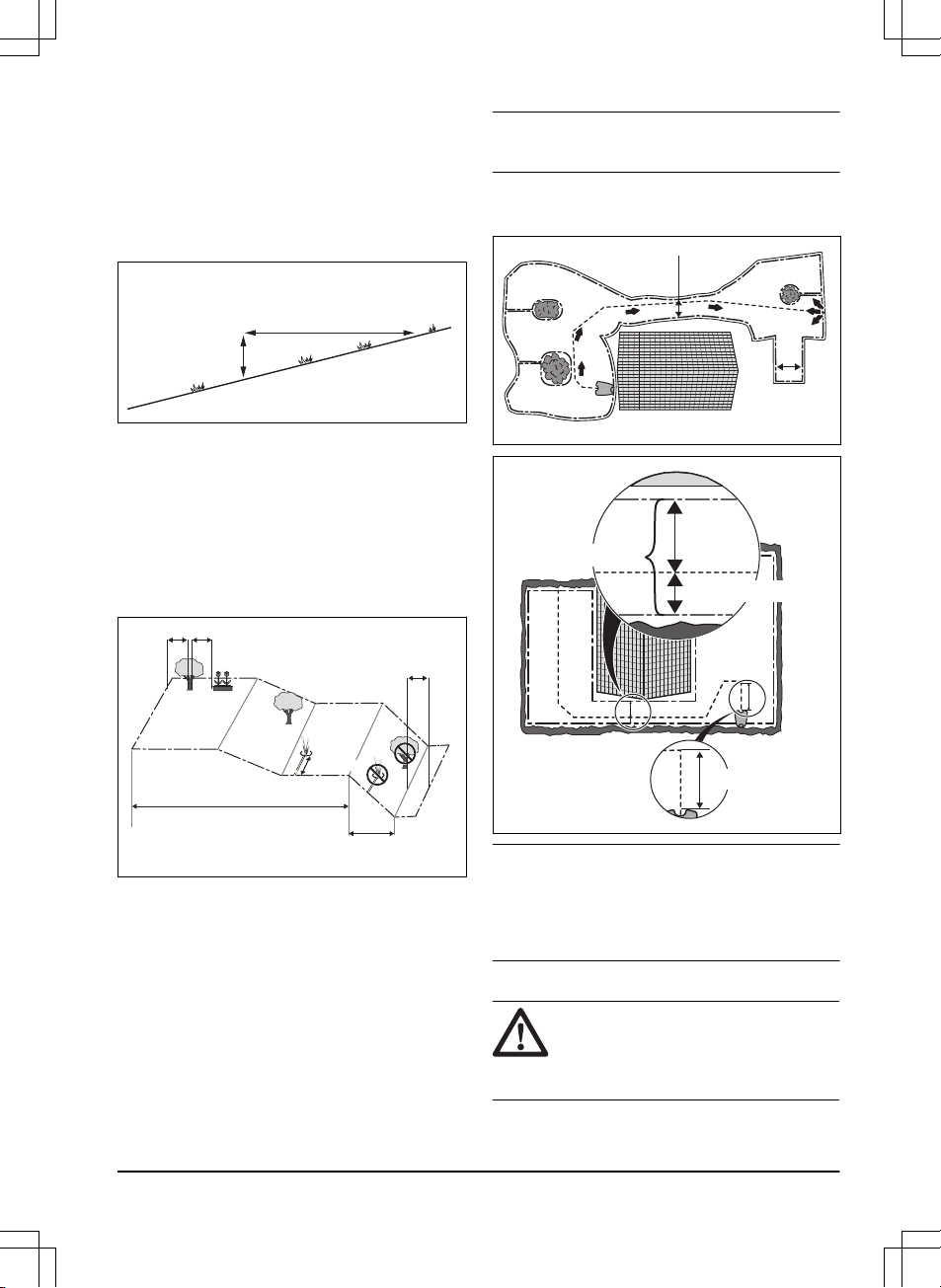
3.4.3.1 To put the boundary wire in a slope
The product can operate in 70% slopes. Slopes
that are too steep must be isolated with the
boundary wire. The gradient (%) is calculated as
height per m. Example: 10 cm / 100 cm = 10%.
10 cm/ 4"
100 cm/ 40"
10%
• For slopes up to 50% steep inside the work
area, the product will operate normally.
Keep a distance of 1.5 m / 5 ft between the
boundary wire and obstacles, or between
obstacles.
• For slopes between 50-70% steep, make
sure that there are no obstacles in the slope.
There must be a distance of 1.5 m / 5 ft from
the bottom of the slope to the boundary wire.
> 1.5 m / 5 ft
> 1.5 m / 5 ft
0% - 50%
50% - 70%
> 1.5 m / 5 ft
• For slopes adjacent to a public road, put a
fence or a protective wall along the outer
edge of the slope.
3.4.3.2 Passages
A passage is a section that has boundary wire on
each side and that connects 2 work areas. The
passage must be a minimum of 2 m / 6.5 ft wide
to get a good cutting result. Short passages can
be as narrow as 60 cm / 2 ft., if a guide wire is
installed through the passage. A long narrow
passage can have a negative impact of the
cutting result.
Note:
If a passage is less than 2 m / 6.5 ft. wide,
install a guide wire through the passage.
A dead end must be a minimum of 2.5 m / 8.5 ft.
wide.
>2 m / 7 ft
>2.5 m / 8.5 ft
>2 m / 7 ft
Max.
distance
>60 cm / 12"
>30 cm / 12"
Note: Make sure that the guide wire has as much
free area as possible to the left of the guide wire
when facing the charging station. Minimum
distance between the guide wire and boundary
wire is 30 cm / 12 in.
3.4.3.3 To make an island
CAUTION:
Do not put a section of
boundary wire across the other. The
sections of boundary wire must be
parallel.
1427 - 002 - 20.12.2019
Installation - 19
CAUTION: Do not put the guide wire
across the boundary wire, for example
a boundary wire that goes to an island.
Some obstacles can withstand a collision, for
example, trees or bushes taller than 15 cm / 6 in.
The product will collide and then turn around with
this type of obstacle. However, obstacles that
slope slightly, for example stones or large trees
with raised roots, must be isolated or removed.
The product can run onto this kind of obstacle
causing the blades to be damaged. Use the
boundary wire to isolate areas inside the work
area by creating islands. When the boundary
wires to and from the island are put close
together, the product can run over the wire.
Note:
To achieve careful and silent operation, it is
recommended to isolate all fixed objects in the
work area.
• Put the boundary wire to and around the
obstacle to make an island.
• Put the 2 sections of boundary wire that run
to and from the obstacle close together
without crossing.
• Put the 2 sections of boundary wire in the
same stake.
• Make sure that there is a minimum of 1.5 m /
5 ft of empty space before an obstacle.
0 cm/ 0 "
1.5 m/ 5 ft 1.5 m/ 5 ft
3.4.3.4 To make a secondary area
Make a secondary area (B) if the work area has 2
areas that are not connected with a passage. The
work area with the charging station is the main
area (A).
Note: The product must be manually moved
between the main area and the secondary area.
B
A
• Put the boundary wire around the secondary
area (B) to make an island. Refer to
To
make an island on page 19
.
Note:
The boundary wire must be put as 1
loop around all of the work area (A + B).
Note: When the product cuts grass in the
secondary area, the
Secondary area
mode
must be selected. Refer to
Secondary area
(2nd area) on page 32
.
20 - Installation
1427 - 002 - 20.12.2019

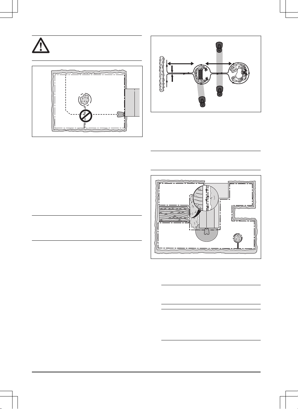
3.4.4 To examine where to put the guide
wire
Put the guide wire from the charging station
through the work area and connect it to the
boundary wire. This product has 3 guide wires.
Use the same approach for all guide wires.
• Put the guide wire in a line at a minimum of
2 m / 7 ft. in front of the charging station.
• Make sure that the guide wire has as much
free area as possible to the left of the guide
wire when facing the charging station.
• Put the guide wire minimum 30 cm / 12 in.
from the boundary wire.
• Do not make sharp bends when you install
the guide wire.
• If the work area has a slope, put the guide
wire in a straight line from the bottom of the
slope to the top of the slope. If it is not
possible to make a straight line, put the
guide wire diagonally across the slope.
CAUTION: Do not put the guide
wire in parallel with the slope, as
the illustration shows. This can
increase the wear on the grass.
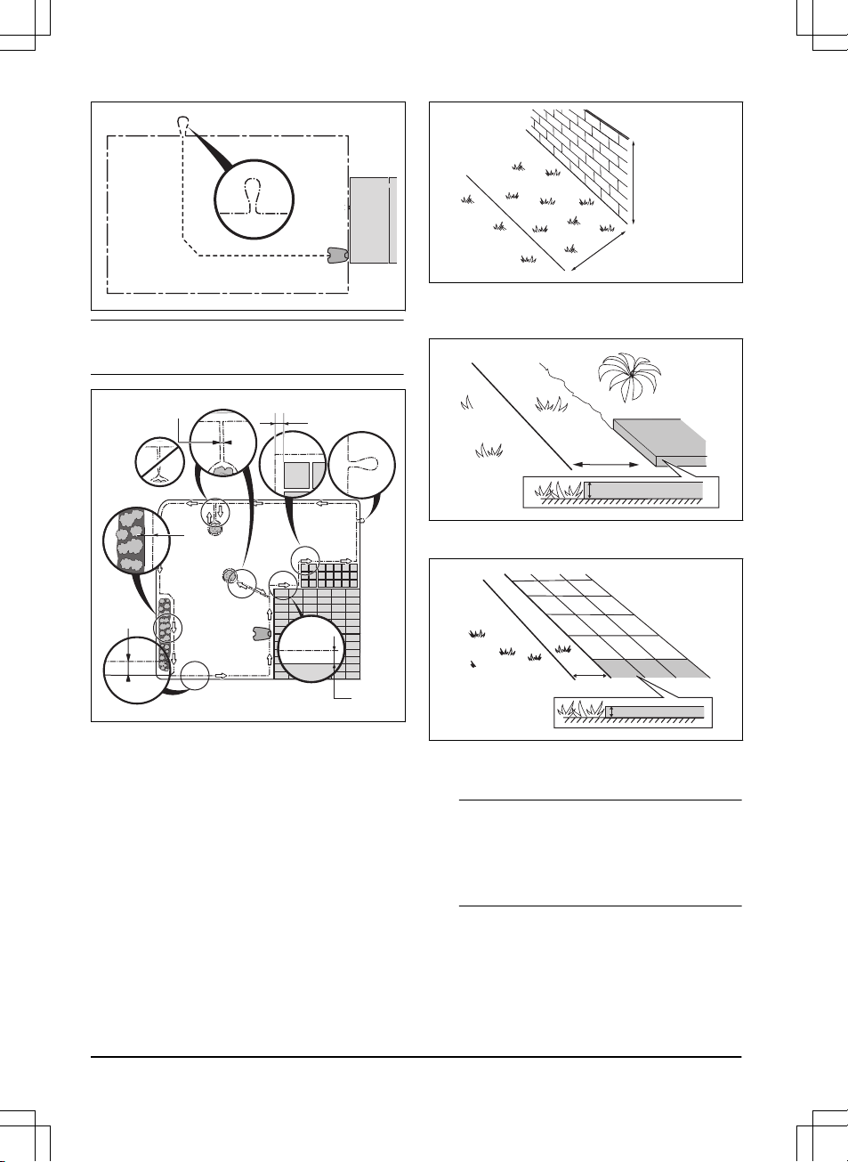
3.4.5 Work area examples
• If the charging station is put in a small area
(A), make sure that the distance to the
boundary wire is at a minimum 3 m / 10 ft. in
front of the charging station.
• If the work area has a passage (B), make
sure that the distance to the boundary wire
is at a minimum 2 m / 6.5 ft. If the passage is
smaller than 2 m / 6.5 ft., install a guide wire
through the passage. Minimum passage
between the boundary wire is 60 cm / 24 in.
• If the work area has areas which are
connected by a narrow passage (B), you
can set the product to first follow and then
leave the guide wire after a certain distance
(C). The settings can be changed in
Lawn
coverage on page 29
.
• If the work area includes a secondary area
(D), refer to
To make a secondary area on
page 20
. Put the product in the secondary
area and select
Secondary area mode
.
B
D
A
C
3.5 Installation of the product
3.5.1 Installation tools
• Hammer/plastic mallet: To simplify putting
the stakes into the ground.
1427 - 002 - 20.12.2019
Installation - 21

• Combination pliers: For cutting the boundary
wire and pressing the connectors together.
• Adjustable plier: For pressing the couplers
together.
• Edge cutter/straight spade: To bury the
boundary wire.
3.5.2 To install the charging station
WARNING: Obey national regulations
about electrical safety.
WARNING: The product is only to be
used with the power supply unit
supplied by Husqvarna.
WARNING: Do not put the power
supply at a height where there is a risk
it can be put in water. Do not put the
power supply on the ground.
WARNING: Do not encapsulate the
power supply. Condensed water can
harm the power supply and increase
the risk of electrical shock.
WARNING: Risk of Electric Shock.
Install only to an earth fault breaker
(RCD) when connecting the power
supply to the wall socket. Applicable to
USA/Canada. If power supply is
installed outdoors: Risk of Electric
Shock. Install only to a covered Class
A GFCI receptacle (RCD) that has an
enclosure that is weatherproof with the
attachment plug cap inserted or
removed.
CAUTION: Do not make new holes in
the charging station plate.
CAUTION: Do not put your feet on the
baseplate of the charging station.
CAUTION: The power supply cable
and extension cable must be outside
the work area to avoid damage to the
cables.
When connecting the power supply, only use a
wall socket that is connected to an earth faultbreaker (RCD).
1. Read and understand the instructions about
the charging station. Refer to
To examine
where to put the charging station on page
16
.
2. Put the charging station in the selected area.
Note: Do not attach the screws for the
charging station to the ground until the guide
wire is installed. Refer to
To install the guide
wire on page 23
.
3. Connect the low-voltage cable to the
charging station.
4. Put the power supply at a minimum height of
30 cm / 12 in.
min 30 cm / 12”
5. Connect the power supply cable to a
100-240V power outlet.
Note:
When the charging station is
connected, it is possible to charge the
product. Place the product in the charging
station while the boundary and guide wires
are being laid. Switch on the product. Refer
to
To switch on the product on page 32
. Do
not continue with any product settings
before the installation is complete.
6. Put the low-voltage cable in the ground with
stakes or bury the cable. Refer to
To put the
wire into position with stakes on page 24
or
To bury the boundary wire or the guide wire
on page 24
.
7. Connect the wires to the charging station
after the installation of boundary wire and
22
- Installation
1427 - 002 - 20.12.2019

guide wire is complete. Refer to
To install
the boundary wire on page 23
and
To
install the guide wire on page 23
.
8. Attach the charging station to the ground
with the supplied screws after the guide wire
is installed. Refer to
To install the guide wire
on page 23
.
3.5.3 To install the boundary wire
CAUTION: Do not put unwanted wire
in a coil. The coil causes interference
with the product.
1. Put the boundary wire around all of the work
area. Start and complete the installation
behind the charging station.
2. Open the connector and put the boundary
wire in the connector.
3. Close the connector with a pair of pliers.
4. Cut the boundary wire 1-2 cm / 0.4-0.8 in.
above each connector.
5. Put the right end of boundary wire into the
channel with the mark "AR".
6. Put the left end of boundary wire into the
channel with the mark "AL".
7. Push the right connector onto the metal pin
on the charging station with the mark "AR".
8. Push the left connector onto the metal pin
on the charging station with the mark "AL".
9. Put the cable mark on the left and right
boundary wire. Do not walk on the charging
station.
3.5.4 To install the guide wire
CAUTION: Twinned cables, or a screw
terminal block that is insulated with
insulation tape are not satisfactory
splices. Soil moisture will cause the
wire to oxidize and after a time result in
a broken circuit.
1. Open the connector and put the wires in the
connector.
2. Close the connector with a pair of pliers.
3. Cut the guide wires 1-2 cm / 0.4-0.8 in.
above each connector.
4. Put the guide wires centrally below the
charging station plate, and push them
through the slot in the charging station
tower.
5. Push the connector onto the metal pin on
the charging station with the mark "G1, G2"
or "G3".
6. Disconnect the charging station from the
power outlet.
7. Put the cable mark on the guide wires.
8. Put the end of the guide wires at the eyelet
on the boundary wire.
9. Cut the boundary wire with a pair of wire
cutters.
10. Connect the guide wires to the boundary
wire with a coupler.
a) Put the 2 ends of the boundary wire
and the end of the guide wires into the
coupler.
1427 - 002 - 20.12.2019
Installation - 23

Note: Make sure that you can see the
end of the guide wires through the
transparent area of the coupler.
b) Push the button on the coupler with an
adjustable pliers.
11. Attach the guide wires to the ground with
stakes or bury the guide wires in the ground.
Refer to
To put the wire into position with
stakes on page 24
or
To bury the boundary
wire or the guide wire on page 24
.
12. Connect he charging station to the power
outlet.
3.6 To put the wire into position with
stakes
CAUTION:
Make sure that the stakes
hold the boundary wire and the guide
wire against the ground.
CAUTION: Cutting the grass too low
right after installation can damage the
wire insulation. Damage to the
insulation may not cause disruptions
until several weeks or months later.
1. Put the boundary wire and the guide wire on
the ground.
2. Put the stakes at a maximum of 75 cm / 30
in. distance from each other.
3. Attach the stakes to the ground with a
hammer or a plastic mallet.
Note:
The wire is overgrown with grass and not
visible after a few weeks.
3.7 To bury the boundary wire or the
guide wire
• Cut a groove in the ground with an edge
cutter or a straight shovel.
• Put the boundary wire or the guide wire 1-20
cm / 0.4-8 in. into the ground.
3.8 To extend the boundary wire or the
guide wire
Note: Extend the boundary wire or the guide wire
if it is too short for the work area. Use original
spare parts, for example couplers.
1. Disconnect the charging station from the
power outlet.
2. Cut the boundary wire or the guide wire with
a pair of wire cutters where it is necessary to
install the extension.
3. Add wire where it is necessary to install the
extension.
4. Put the boundary wire or the guide wire into
position.
5. Put the wire ends into a coupler.
Note: Make sure that you can see the ends
of the boundary wire or the guide wire
through the transparent area of the coupler.
6. Push the button on the coupler with an
adjustable pliers.
7. Put the boundary wire or the guide wire into
position with stakes.
8. Connect the charging station to the power
outlet.
24
- Installation
1427 - 002 - 20.12.2019

3.9 After the installation of the product
3.9.1 To do a visual check of the charging
station
1. Make sure that the indicator LED lamp on
the charging station has a green light.
2. If the indicator LED lamp does not have a
green light, do a check of the installation.
Refer to
Indicator lamp in the charging
station on page 49
and
To install the
charging station on page 22
.
3.10 Automower® Connect
The product has Automower® Connect included
from factory.
The app gives 2 modes of connectivity: Longrange cellular connectivity and Short-range
Bluetooth® connectivity.
The product can connect to mobile devices that
have the Automower® Connect app installed.
Automower® Connect is a free app for your
mobile device. The Automower® Connect app
gives extended functions to your Husqvarna
product. You can:
• See the status of your product.
• Change settings to your product.
• Get extended product information.
• Get an alarm if the product moves out of the
work area.
• See statistics of your product.
Note:
All countries do not support Automower
®
Connect because of regional specified cellular
systems. The included Automower® Connect
lifetime service only applies if there is a third part
sub-supplier of 2G/3G/4G available in the
operational area.
3.10.1 To install the Automower® Connect
app
1. Download the Automower® Connect app on
your mobile device.
2. Sign up for a Husqvarna account in the
Automower® Connect app.
3. Log in to your Husqvarna account in the
Automower® Connect app.
3.10.2 To pair Automower® Connect and
the product
1. Do step 1-6 in
To start the product for the
first time on page 26
.
2. Obey the instructions in the Automower
®
Connect app.
3.10.3 My mowers
When you choose
My mowers
you can manage
all the products paired to your account, as well as
add new ones. If there are several paired
products it is possible to select one of them as
Current mower.
To pair a new product to the Automower
®
Connect app:
1. Select the plus sign (+).
2. Select model.
3. Obey the instructions in the Automower
®
Connect app to finish the pairing.
3.10.4 Firmware over the air (FOTA)
The product has a function that automatically
downloads new firmware. When a new firmware
is available, a notification shows in the app where
you can select to install the new firmware. In the
factory setting this function is enabled.
3.10.4.1 To set the Firmware over the air (FOTA)
1. Select
My Mowers
.
2. Select
Mower information
for the current
mower.
3. Select
on/off
to enable or disable the
function.
3.10.5 Automower® Direct
Automower® Direct uses short-range Bluetooth
®
communication, and is included in Automower
®
535 AWD.
Husqvarna cannot guarantee the time period or
coverage of the long-range cellular connectivity.
It is possible to communicate with the product
through Bluetooth® if you are in short-range of
the product. You can use Automower® Direct
without a Husqvarna account as long as you
have the product PIN code.
1427 - 002 - 20.12.2019
Installation - 25

3.10.5.1 To start to use Automower® Direct
1. Download the Automower® Connect app on
your mobile device.
2. Select Automower® Direct on the start
screen of the Automower® Connect app.
3. Start Bluetooth® on your mobile device and
on the product, refer to
To start the product
for the first time on page 26
.
4. Go to the
Settings
symbol in the display and
activate Bluetooth®.
5. Select the product to pair with in the
Automower® Connect app.
6. Enter the PIN code for the product.
Note: You have access to the menus and
functions as long as you are in Bluetooth® shortrange.
3.10.6 User interface overview
The user interface overview below shows examples of Automower® Connect.
Automower® Connect
ERROR
Charging station Blocked
MORE DETAILS
Schedule Map
My Automower
R
MOWING
Mowing session ends 13:30
PARK PAUSE
Schedule Map
My Automower
6
R
PARKED
Next start tomorrow 16:30
PARK START
Schedule Map
6
My Automower
R
PAUSED
PARK START
Schedule Map
My Automower
R
6
6
3.11 To start the product for the first
time
When the product is switched on for the first time,
there are some basic settings to do before the
product can start to operate.
1. Push the ON/OFF button for 3 seconds to
switch on the product.
Note: The Bluetooth® pairing mode is on for
3 minutes and the LED light is flashing blue.
If the product does not pair with Bluetooth
®
in 3 minutes, switch off the product. Wait
until the LED status indicator is not lit, and
then switch on the product again.
2. Enter the factory PIN code.
3. Log on to your Husqvarna account in the
Automower® Connect app to pair your
product with Automower® Connect.
Note: It is recommended to pair your product
with Automower® Connect to get access to
all functions in the product. If it is not
necessary to pair your product with
Automower® Connect, push the
arrow
symbol to continue to the menu.
4. Start Bluetooth® on your mobile device.
5. Select
My mowers
in the Automower
®
Connect app, and then select the plus sign
(+).
6. Select model. The Automower® Connect
app searches for available products within
short-range (Bluetooth®).
26 - Installation 1427 - 002 - 20.12.2019

7. Select product.
8. Obey the instructions in the Automower
®
Connect app.
3.12 Settings in Automower® Connect
The product has factory settings but
the settings can be adapted to each
work area.
3.12.1 Schedule
In
Schedule
you can change the
schedule settings for the product. To
change the settings, obey the
instructions in the Automower
®
Connect app.
The schedule function controls which work hours
the product should operate and not operate.
When the product is not operating it is parked in
the charging station. The operating hours and
days can be seen in an overview in the
Automower® Connect app.
The default schedule setting allows the product to
operate around the clock 7 days a week. This is
normally a suitable setting for a work area
corresponding to the maximum capacity. If the
work area is less than the maximum capacity the
schedule should be used to minimize wear on the
grass and to the product.
To calculate the schedule setting, refer to
To
calculate the schedule setting on page 27
.
3.12.1.1 To edit the schedule settings
1. Select
Settings > Schedule > Edit
in the app.
2. Select the pencil symbol in the app.
3. Select which days of the week and hours the
product must operate.
4. Select
Save
.
3.12.1.2 To add a new schedule setting
1. Select
Settings > Schedule > Edit
in the app.
2. Select the plus sign in the app.
3. Select which days of the week and hours the
product must operate.
4. Select
Save
.
3.12.1.3 To calculate the schedule setting
1. Calculate the dimension of your lawn in m2 /
yd2.
2. Divide the m
2
/ yd2 of the lawn with the
approximate operation capacity. Refer to
table below.
3. The result is equal to the number of hours
that the product must operate each day.
Note: The operation capacity is approximate and
is calculated for flat and open work area. If the
work area has a lot of slopes or obstacles, you
need to increase the
Schedule
settings.
Model Approximate operation ca-
pacity, m2 / yd2 / h
Automower® 535
AWD AWD
146 / 175
Example: A lawn of 500 m2 / 600 yd2, cut with an
Automower® 535 AWD AWD.
500 m2 / 146 ≈ 3.5 h.
600 yd2 / 175 ≈ 3.5 h.
Days /
week
h / day Schedule settings
7 3.5 10:00 - 13:30 / 10
am - 1.30 pm
3.12.2 Operation
In
Operation
you can change the
operation settings of the product. To
change the settings, obey the
instructions in the Automower
®
Connect app.
3.12.2.1 Weather timer
The
Weather timer
automatically adjust the
cutting time to the growth of the grass. The
product is not permitted to operate more than the
schedule settings.
Note:
When using
Weather timer
, it is
recommended to make as much operating time
as possible available for the
Weather timer
. Do
not restrict the schedule more than necessary.
The first operation of the day is set by the
schedule settings. The product always complete
1 mowing cycle, and then the
Weather timer
selects if the product will continue to operate or
not.
1427 - 002 - 20.12.2019
Installation - 27

Note: The
Weather timer
is reset if the product
does not operate for more than 50 hours, or if a
Reset of all user settings
is done. The
Weather
timer
is not changed if a
Reset of schedule
settings
is done.
To set the Weather timer
1. Select
Settings > Operation
in the app.
2. Select
on/off
to enable or disable the
Weather timer
.
Note: If the cutting results are not
satisfactory, the cutting time can be
adjusted. Set the cutting time
High
to cut for
a longer time or
Low
to cut for a shorter
time.
3. Select
Save
.
3.12.2.2 ECO mode
If
ECO mode
is activated, it switches off the
signal in the boundary loop, the guide wire and
the charging station, when the product is parked
or is charging.
Note: Use
ECO mode
to save energy and avoid
interference with other equipment, for example
hearing loops or garage doors.
Note: To start the product manually in the work
area, push the STOP button before you remove
the product from the charging station. If not, the
product can not be started in the work area.
To set the ECO mode
1. Select
Settings > Operation
in the app.
2. Select
on/off
to enable or disable the
ECO
mode
function.
3. Select
Save
.
3.12.3 Installation
In
Installation
you can change the
installation settings of the product. To
change the settings, obey the
instructions in the Automower
®
Connect app.
3.12.3.1 To find the charging station
The product can be set to search for the charging
station in 3 methods:
•
Charging station signal
•
Follow boundary wire
•
Follow guide wire
The factory setting is set to use the 3 search
methods at the same time. Use the factory
setting to find the charging station as fast as
possible and to keep the risk of tracks on the
lawn to a minimum. The product always starts to
search for the
Charging station signal
. After a
specified time interval, it also uses
Follow guide
and
Follow boundary wire
.
Causes why the product cannot follow the wire:
• Obstacles near the wire have not been
isolated.
• The charging station, the boundary wire or
the guide wire are not installed according to
the instructions in
To examine where to put
the charging station on page 16
,
To examine
where to put the boundary wire on page 17
and in
To examine where to put the guide
wire on page 21
.
To change the signal range of the charging
station
For some installations it is necessary to decrease
the signal of the charging station. For example
when the charging station is put near an obstacle
such as a bush or wall and the signal reaches to
the other side of the obstacle. The product knows
that it is close to the charging station and tries to
dock, but the objects prevents it. The options are
min, avg
(average) or
max
.
Note:
It is usually better to move the charging
station, than to decrease the range of the
charging station signal.
1. Select
Settings > Installation > Find charging
station
in the app.
2. Select signal range.
3. Select
Save
.
To set the delay time for the guide wire and the boundary wire
1. Select
Settings > Installation > Find charging
station
in the app.
2. Select
on/off
to enable or disable to follow
the wire.
28
- Installation
1427 - 002 - 20.12.2019

3. Move the horizontal bar to set the time
delay.
4. Select
Save
.
3.12.3.2 Lawn coverage
The product has GPS Assisted Navigation that
helps the product select the most optimal
operation.
Use the
Lawn coverage
function to set the
settings to manual.
To set the GPS function
1. Select
Installation > Settings > Lawn
coverage
in the app.
2. Select
on/off
to disable or enable the GPS
function.
Note: When GPS assisted navigation is
enabled it is used while there is a GPS
service. The GPS assisted navigation is
used even if manual settings have been
made. Only when GPS service is not
available, the manual settings are used.
3. Select
Save
.
To set the Lawn Coverage function
The
Lawn Coverage
function is used to guide the
product to remote parts of the work area. If the
work area includes remote parts that are
connected with narrow passages, the
Lawn
Coverage
function is useful to to keep a well-cut
lawn in all parts of the yard. You can set a
maximum of 5 remote areas where the product
starts to cut the lawn.
Each area can be enabled or disabled, without
having to enter the settings again.
1. Select
Settings > Installation > Lawn
coverage
in the app.
2. Select
on/off
to disable the GPS function to
set the
Lawn Coverage
.
3. Select on/off
Area 1-5
to activate the area.
4. Move the horizontal bar to set which wire the
product will follow. The product can follow
Boundary wire left, Boundary wire right
or
one of the guide wires.
5. Move the horizontal bar to set the distance
the product must follow the wire. The
product then leaves the wire and starts to
cut the lawn. Refer to
To measure the
distance from the charging station on page
29
.
6. Move the horizontal bar to set how often the
product goes to each area. At all other
times, the products starts to cut near the
charging station. The percentage is equal to
the percentage of the area in relation to the
complete work area.
a) Measure the area.
b) Divide the area with the complete work
area.
c) Convert the result to %.
d) Move the horizontal bar to set the
distance from the charging station.
7. Select
Save
.
The default settings lets the product follow the
guide wire 300 m / 980 ft. in 20% of the times it
leaves the charging station. If the guide wire is
less than 300 m / 980 ft. the product will follow it
to the point where the guide wire is connected to
the boundary wire.
To measure the distance from the charging station
1. Put the product in the charging station.
2. Select
Settings > Installation > Lawn
coverage
in the app.
3. Move the horizontal bar to set the distance
to the charging station to maximum.
4. Select
Test: Area 1-5 setup
.
5. Follow the instructions in the app to start the
test.
6. Push the STOP button when the product is
at the distance you select to measure. The
distance shows in the app.
To do a test of the Lawn Coverage function
1. Put the product in the charging station.
2. Select
Settings > Installation > Lawn
coverage
in the app.
3. Select
Test: Area 1-5 setup
.
4. Follow the instructions in the app to start the
test.
5. The product will run to the starting point for
this area.
3.12.3.3 Drive Past Wire
The front of the product always moves past the
boundary wire by a specified distance before the
1427 - 002 - 20.12.2019
Installation - 29
product moves back into the work area. The
factory setting for the
Drive Past Wire function
function is 31 cm. You can select a distance of
20-50 cm.
Note: With the factory setting the product will cut
11 cm past the wire.
To set the Drive past wire
1. Select
Settings > Installation > Drive past
wire
in the app.
2. Move the horizontal bar to set the distance.
3. Select
Save
.
3.12.3.4 Starting point
The
Starting point
function allows you to control
how far the product drives forward from the
charging station before it starts to operate. Use
this function if the charging station is placed in an
area with limited space, for example under a
veranda.
Note: Starting point must not be set to a distance
longer than the distance the guide wire is
installed in a line in front of the charging station.
Refer to
To examine where to put the guide wire
on page 21
.
To set the starting point
1. Select
Settings > Installation > Starting point
in the app.
2. Move the horizontal bar to set the distance.
3. Select
Save
.
3.12.4 Accessories
In
Accessories
you can change the
settings of the product accessories. To
change the settings, obey the
instructions in the Automower
®
Connect app.
3.12.4.1 To avoid collisions with the mower
house
When this option is enabled, the wear on the
product and the house is reduced, but it can
result in more uncut grass around the charging
station.
1. Select
Settings > Installation > Mower house
in the app.
2. Select
on/off
to enable or disable the
function.
3. Select
Save
.
3.12.5 General (Bluetooth® only)
This function is used to set time and
date, or to reset to default settings. To
change the settings, obey the
instructions in the Automower
®
Connect app.
3.12.5.1 Time & date
The time and date can be changed manually, or
by using the time and date from the mobile
device.
To set the time & date
1. Select
Settings > General > Time & Date
in
the app.
2. Select
Time & Date from phone
or select the
pencil to enter the correct time and date.
3. Select
Save
.
3.12.5.2 Reset to factory settings
The user settings can be reset to factory settings.
Note:
PIN code, Loop signal, Messages
and
Date
& Time
will not be reset.
To reset to factory settings
1. Select
Settings > General > Reset
in the
app.
2. Select
Reset to factory settings
.
3.12.6 Security (Bluetooth® only)
The security settings controls the PIN
code, the GeoFence and other security
functions. To change the settings,
obey the instructions in the
Automower® Connect app. The correct
PIN-code must be entered to get
access to the
Security
menu in the
Automower® Connect app.
3.12.6.1 New loop signal
The loop signal is randomly selected to create a
unique link between the product and the charging
station. In rare cases, there may be a need to
generate a new signal, for instance if 2 adjacent
installations have a very similar signal.
30
- Installation
1427 - 002 - 20.12.2019

To create a New loop signal
1. Put the product in the charging station.
2. Select
Settings > Security > New loop signal
in the app.
3. Select
Create new loop signal
.
4. Select
Save
.
5. Wait for confirmation that the loop signal has
been generated. This usually takes about 10
seconds.
3.12.6.2 To change the PIN code
1. Select
Settings > Security > Change PIN
code
in the app.
2. Enter the PIN code.
3. Enter the new PIN code.
4. Enter the new PIN code to confirm.
5. Make a note of the new PIN code in Memo.
Refer to
Introduction on page 3
.
3.12.6.3 Theft protection
In the
Theft protection
menu it is possible to set
the alarm duration and also what events should
trigger the alarm. The factory setting is to require
PIN code and the alarm duration is 1 min.
Alarm duration
There is a possibility to set how long the alarm
signal should last. A setting between 1 and 10
minutes is possible.
STOP button pressed
If the alarm
"STOP button pressed"
is enabled,
the alarm goes off if someone presses the STOP
button and the PIN code is not entered within 30
seconds.
Carried away
If the alarm
Carried away
is enabled, the product
senses unexpected motions, and the alarm goes
off.
To set the Theft protection
1. Select
Settings > Security > Theft protection
in the app.
2. Select the on/off button to enable or disable
the
STOP button pressed
and
Carried away
.
3. Move the horizontal bar to select the
duration of the alarm.
3.12.6.4 GeoFence
GeoFence is a GPS-based theft protection that
makes a virtual fence for the product. If the
product is more than 500 m / 1650 ft away from
the center position the product will be deactivated
and an alarm will start. The PIN code is needed
to deactivate the alarm and to start the product
again.
To set the center position for the GeoFence function
1. Select
Settings > Security > GeoFence
in
the app.
2. Put the product in a central position of the
work area.
3. Select the
on/off
button to enable or disable
the GeoFence function. The center position
will be set to the current position of the
product.
3.12.7 Automower® Connect (Bluetooth
®
only)
In
Automower® Connect
you can
enable or disable the Automower
®
Connect module. You can also see the
signal strength, connectivity status,
initiate new pairing or remove the
product from the paired accounts.
3.12.8 Messages
In this menu the previous fault and information
messages can be found. For some of the
messages, there are tips and advice to help to
rectify the fault.
If the product is disrupted in any way, for
example it is trapped or the battery is low, a
message is saved relating to the disruption and
the time it happened.
If the same message is repeated several times,
this may indicate that an adjustment to the
installation or the product is required. Refer to
Installation on page 16
.
1427 - 002 - 20.12.2019
Installation - 31

4 Operation
4.1 To switch on the product
WARNING: Read and understand the
safety chapter before you switch on
the product.
WARNING: Keep your hands and feet
away from the rotating blades. Do not
put your hands or feet near or below
the product when the motor is running.
WARNING: Do not use the product
when persons, especially children, or
animals, are in the work area.
1. Push the ON/OFF button for 3 seconds to
switch on the product.
Note: Make sure that the STOP button is
pushed down.
2. Use the Automower® Connect app to enter
the PIN code. The correct PIN code must be
entered to get access to the menu. If the
incorrect PIN code is entered 5 times, the
product is locked for a time. The lock is
extended for each new incorrect try.
3. Select the desired operating mode in the
Automower® Connect app. Refer to
Operating modes on page 32
.
4. Push the START button to start the product.
If the product is parked in the charging
station, it will only leave the charging station
when the battery is fully charged and if the
Schedule
is set to let the product operate.
4.2 Operating modes
In the Automower® Connect menu the following
operation modes can be selected:
• Main area
• Secondary area
• Park
4.2.1 Main area
Main area
is the standard operating mode where
the product mows and charges automatically.
4.2.2 Secondary area (2nd area)
To mow secondary areas the operating mode
Secondary area (2nd area)
must be selected. In
this mode, the operator must move the product
manually between the main area and the
secondary area. The product mows for a selected
period of time or until the battery is empty.
4.2.3 Park
When the
Park
mode is selected the following
operation selections can be chosen:
• Park until further notice
• Park for a specific number of hours
4.2.3.1 Park until further notice
The product goes to the charging station where it
stays until you select a different operating mode.
32
- Operation
1427 - 002 - 20.12.2019

4.2.3.2 Park for a selected number of hours
The product goes to the charging station where it
stays for a selected number of hours, then it
automatically goes to the usual operation that is
set in the
Schedule
settings. This operation
selection is applicable when it is necessary to
pause operation, for example for temporary
irrigation or work on the lawn.
4.3 To stop the product
1. Push the STOP button on top of the product.
The product stops and the blade motor stops.
4.4 To switch off the product
1. Push the STOP button to stop the product.
2. Push the ON/OFF button for 3 seconds to
switch off the product.
3. Make sure that the LED status indicator is
not lit.
Note:
If the LED status indicator is lit or is
flashing in any color the product is not
switched off. Refer to
LED status indicator
on page 10
.
Note: The product cannot be switched off
when it stands in the charging station.
WARNING: The product must be
switched off before any maintenance is
done, or if the product must be moved
from the work area.
4.5 To charge the battery
When the product is new or has been in storage
for a long period, the battery can be empty,
charge the battery before you start the product. In
the
Main area
mode, the product automatically
changes between mowing and charging.
WARNING: Only charge the product
with a charging station and a power
supply which the product is intended
for. Incorrect use may result in electric
shock, overheating or leakage of
corrosive liquid from the battery.
In the event of leakage of electrolyte,
flush with water and seek medical help
if it comes in contact with the eyes and
etc.
1. Put the product in the charging station.
2. Put the product in as far as possible and
make sure it is connected to the charging
station.
The battery status can be monitored on the
status bar of the display.
Note:
If the battery is empty the product needs to
charge for a longer time period before the
product is possible to start.
4.6 To adjust the cutting height with
Automower® Connect
The cutting height can be varied from MIN (3 cm /
1.2 in.) to MAX (7 cm / 2.8 in.).
1427 - 002 - 20.12.2019
Operation - 33

Note: During the first weeks after a new
installation, the cutting height must be set to MAX
to avoid damaging the loop wire. After this, the
cutting height can be lowered step by step every
week until the desired cutting height has been
reached.
1. Select
Settings > Cutting height
.
2. Move the horizontal bar to set the cutting
height.
3. Select
Save
.
34 - Operation 1427 - 002 - 20.12.2019

5 Maintenance
5.1 Introduction - maintenance
WARNING: The product must be
switched off before any maintenance is
done. The product is disabled when
the LED status indicator is not lit.
WARNING: Wear protective gloves.
For better operation and longer service life, make
sure to clean the product regularly and replace
worn parts. All maintenance and servicing must
be done according to Husqvarna's instructions.
Refer to
Warranty on page 59
.
When the product is first used, the blade disc and
blades should be inspected once a week. If the
amount of wear during this period has been low,
the inspection interval can be increased.
It is important that the blade disc rotates easily.
The edges of the blades should not be damaged.
The lifetime of the blades varies immensely and
depends for instance on:
• Operating time and size of the work area.
• Type of grass and seasonal growth.
• Soil, sand and use of fertilizers.
• The presence of objects such as cones,
windfalls, toys, tools, stones, roots and the
like.
The normal life is 3 to 6 weeks when used under
favorable conditions. Refer to
Replace the blades
on page 36
on how to replace the blades.
Note:
Working with blunt blades gives a poorer
mowing result. The grass is not cut cleanly and
more energy is needed resulting in the product
not mowing such a large area.
5.2 Clean the product
CAUTION:
Never use a high-pressure
washer to clean the product. Never
use solvents for cleaning.
The product does not operate satisfactorily in
slopes if the wheels are blocked with grass. Use
a soft brush to clean the product.
Husqvarna recommends to use a special
cleaning and maintenance kit, available as
accessory. Speak to your Husqvarna
representative for more information.
5.2.1 To clean the blade disc
Examine the blade disc and blades weekly.
1. Switch off the product. Refer to
To switch off
the product on page 33
.
2. Turn the product upside down or put it on its
side. Put the product on a soft and clean
surface to prevent scratching the product
body.
3. Clean the blade disc with a brush.
1427 - 002 - 20.12.2019
Maintenance - 35

4. Make sure that the blade disc can rotate
freely.
5. Make sure that the blades are not damaged
and can pivot freely.
5.2.2 Chassis
Clean the underside of the chassis. Brush or
wipe with a damp cloth.
5.2.3 Wheels
Clean around the wheels. Grass on the wheels
can impact on how the product performs in
slopes.
5.2.4 The body of the product
Use a moist, soft sponge or cloth to clean the
body of the product. If the body of the product is
dirty, use a mild soap solution to clean it.
5.2.5 Charging station
WARNING: Use the plug to disconnect
the charging station before any
maintenance, or cleaning of charging
station or power supply.
Clean the charging station regularly from grass,
leaves, twigs and other objects that may impede
docking.
5.3 Replace the blades
WARNING:
Use blades and screws of
the right type. Husqvarna can only
guarantee safety when using original
blades. Only replacing the blades and
reusing the screw can result in a screw
wearing during mowing. The blades
can then be propelled from under the
body and cause serious injury.
Replace worn or damaged parts for safety
reasons. Even if the blades are intact, they
should be replaced on a regular basis for the best
mowing result and low energy usage. All 3 blades
and screws must be replaced at the same time to
obtain a balanced cutting system. Use
Husqvarna original blades embossed with the
crowned H-mark logotype, refer to
Warranty
terms on page 59
.
5.3.1 To replace the blades
1. Switch off the product. Refer to
To switch off
the product on page 33
.
2. Put on protective gloves.
3. Turn the product upside down. Place the
product on a soft and clean surface to avoid
scratching the body.
4. Rotate the skid plate so that its holes align
with the screws for the blade.
36
- Maintenance
1427 - 002 - 20.12.2019

5. Remove the 3 screws. Use a manual
straight slot or cross-tip screwdriver.
6. Remove each blade and screw.
7. Fasten new blades and screws.
8. Check that the blades can pivot freely.
5.4 To replace the top covers
The top cover is an accessory available in
different colors. Speak to your local Husqvarna
representative for more information.
CAUTION:
Clean grass and dirt from
the product before you remove the
covers.
5.4.1 To remove the front top cover
1. Switch off the product. Refer to
To switch off
the product on page 33
.
2. Remove the front top cover from the snapon clips on the product.
3. Lift the front top cover.
5.4.2 To install the front top cover
1. Put the front top cover on the snap-on clips.
1427 - 002 - 20.12.2019
Maintenance - 37

2. Push the front top cover into position.
5.4.3 To remove the rear top cover
1. Switch off the product. Refer to
To switch off
the product on page 33
.
2. Turn the rear body to the left or right side.
3. Put a protection between the cover and the
link arm. This is to prevent damage to the
top cover.
4. Pull up the top cover.
5. Remove the top cover.
38
- Maintenance
1427 - 002 - 20.12.2019

5.4.4 To install the rear top cover
1. Put the top cover on the rear body.
2. Put the top cover in position (A) and push
the 2 magnets to assemble the top cover
(B).
A
B
5.5 Battery
WARNING:
Only charge the product
using a charging station and power
supply which is intended for it.
Incorrect use may result in electric
shock, overheating or leakage of
corrosive liquid from the battery. In the
event of leakage of electrolyte flush
with water and seek medical help if it
comes in contact with the eyes etc.
WARNING: Use only original batteries
recommended by the manufacturer.
Product safety cannot be guaranteed
with other batteries. Do not use nonrechargeable batteries.
CAUTION: The battery must be
charged fully before winter storage. If
the battery is not fully charged it can
be damaged and in certain cases be
rendered useless.
The charging time can vary depending on,
among other factors, the ambient temperature.
Below indicates that the battery is getting old and
eventually needs replacing:
• The operating time for the product is shorter
than normal between charges. This leads to
more charging cycles than normal, which
increases the risk of tracks forming near the
charging station.
• The product is frequently found standing out
on the lawn with
Empty battery
message.
This indicates that the product does not
have battery capacity enough to find the
charging station.
The battery is fine as long as the product
maintains a well-cut lawn.
Note:
Battery life is dependent on the length of
the season and how many hours a day the
product is operating. A long season or many
hours of use a day means that the battery must
be replaced more regularly.
Contact your local Husqvarna representative to
replace the battery.
5.6 Winter service
Take your product to your Husqvarna central
service for service prior to winter storage.
Regular winter service will maintain the product in
good condition and create the best conditions for
a new season without any disruptions.
Service usually includes the following:
• Thorough cleaning of the body, the chassis,
the blade disc and all other moving parts.
1427 - 002 - 20.12.2019
Maintenance - 39

• Testing of the product’s function and
components.
• Checking and, if required, replacing wear
items such as blades and bearings.
• Testing the product’s battery capacity as
well as a recommendation to replace battery
if necessary.
• If new firmware is available, the product is
updated.
40 - Maintenance 1427 - 002 - 20.12.2019

6 Troubleshooting
6.1 Introduction - troubleshooting
In this chapter, a number of messages are listed which may be shown in Automower® Connect if there
is a malfunction. There is a proposal as to the cause and steps to take for each message. This chapter
also presents some symptoms that can guide you if the product does not work as expected. More
suggestions for steps to take in the event of malfunction or symptoms can be found on
www.husqvarna.com.
6.2 Fault messages
The table below shows a number of fault messages that may be shown in Automower® Connect. Some
of the errors can be confirmed in the Automower® Connect and some the message needs to be
1427 - 002 - 20.12.2019 Troubleshooting - 41
confirmed on the product. Contact your local Husqvarna representative if the same message appears
often. For more information, refer to
Messages on page 31
.
Message Cause Action
No loop signal
The power supply or the voltage cable
are not connected.
Examine the LED status on the charging station. If the LED is not lit, it indicates that there is no power. Examine
the wall socket connection and whether
an earth-fault breaker has tripped.
Make sure that the low voltage cable is
connected to the charging station.
The power supply or low voltage cable
are damaged.
Replace the power supply or low voltage cable.
The boundary wire is not connected to
the charging station.
Make sure that the boundary wire connectors are fitted properly to the charging station. Replace connectors if damaged. Refer to
To install the charging
station on page 22
.
The boundary wire is broken. Check the signal given by the LED on
the charging station. If the LED indicates break in the boundary wire, find
out where the break is. Replace the
damaged section of the loop with a new
loop wire and splice using an original
coupler. Refer to
Find breaks in the
loop wire on page 51
.
ECO mode
is activated and the product has attempted to start outside the
charging station.
Put the product in the charging station.
Start the product and close the hatch.
The pairing between the product and
the charging station is lost.
Put the product in the charging station
and generate a new loop signal. Refer
to
To create a New loop signal on page
31
.
The boundary wire is crossed on its
way to and from an island.
Make sure that the boundary wire is installed correctly. Refer to
To install the
boundary wire on page 23
.
Disturbances from metal objects (fences, reinforcement steel) or buried cables.
Move the boundary wire and/or make
more islands in the work area to increase the signal strength.
Wheel motor
blocked
Grass or other object has wrapped
around the drive wheel.
Examine the drive wheel and remove
the grass or other object.
Wheel drive problem
42 - Troubleshooting 1427 - 002 - 20.12.2019

Message Cause Action
Cutting system
blocked
Grass or other object has wrapped
around the blade disc.
Examine the blade disc and remove the
grass or other object.
The blade disc lies in a pool of water. Move the product and prevent the col-
lection of water in the work area.
Message Cause Action
Trapped
The product is stuck in a small area behind a number of obstacles.
Examine if there are any obstacles
which make it hard for the product to
move away from this location.
Wrong PIN code
Wrong PIN code has been entered.
Five attempts are permitted, and the
product is then blocked for a period of
time.
Enter the correct PIN code. If the PIN
code is incorrect, use the link in the app
to send the PIN code to your registered
e-mail address. If you have not registered the e-mail address, contact your
local Husqvarna representative.
Empty battery
The product cannot find the charging
station.
Change the position of the guide wire.
Refer to
To install the guide wire on
page 23
.
Check the installation settings about
how to find the charging station. Refer
to
To find the charging station on page
28
.
The battery is spent. Replace the battery. Refer to
Battery
on page 39
.
The charging station’s antenna is defective.
Check if the indicator lamp in the
charging station flashes red. Refer to
Indicator lamp in the charging station
on page 49
.
No drive
The product is caught in something and
has been slipping.
Free the product and rectify the reason
for the lack of drive. If it is due to wet
grass, wait until the lawn has dried before using the product.
The work area includes a steep slope. Maximum guaranteed slope is 70%.
Steeper slopes should be isolated. Refer to
To put the boundary wire in a
slope on page 19
.
The guide wire is not installed correctly
in a slope.
Make sure that the guide wire is installed diagonally across the slope. Refer
to
To install the guide wire on page 23
.
Wheel motor overloaded
The product is caught in something. Free the product and rectify the reason
for the lack of drive. If it is due to wet
grass, wait until the lawn has dried before using the product.
1427 - 002 - 20.12.2019
Troubleshooting - 43

Message Cause Action
Charging station
blocked
The contact between the charging
strips and contact strips may be poor
and the product has made a number of
attempts to charge.
Put the product in the charging station
and check that the charging strips and
contact strips make good contact.
Clean the contact and charging plates.
An object causes a blockage and the
product cannot enter the charging station.
Remove the object.
The baseplate is tilted or bent.
Make sure that the baseplate is put on
level ground.
Stuck in charging
station
The product slips on the baseplate. Clean the baseplate.
There is an object in the way of the
product preventing it from leaving the
charging station.
Remove the object.
Upside down
The product is leaning too much or has
turned over.
Turn the product the right way up.
Mower tilted
The product is tilted more than the
maximum angle.
Move the product to a flat area.
Lifted
A blockage has activated the lift senors
and caused the product to stop.
Remove the product from the blockage.
If the problem remains it requires action
by authorized service technician.
Collision sensor
problem
The product body can not move freely
around its chassis.
Make sure that the product body can
move freely around its chassis.
If the problem remains, the message
requires action by authorized service
technician.
Slope too steep
Mower stopped because the slope is
too steep.
Change the installation of the boundary
wire to exclude this steep part of the
work area. Refer to
To examine where
to put the boundary wire on page 17
.
Alarm! Mower
switched off
The alarm was activated because the
product was switched OFF.
Adjust the security level in the
Security
menu, refer to
Security (Bluetooth® on-
ly) on page 30
.
Alarm! Mower
stopped
The alarm was activated because the
product was stopped.
Alarm! Mower was
moved
The alarm was activated because the
product was moved.
Alarm! Outside geofence
The alarm was activated because the
mower was outside its GeoFence.
Adjust the theft protection area (GeoFence) in the
Automower Connect
menu.
44 - Troubleshooting
1427 - 002 - 20.12.2019

Message Cause Action
Electronic problem
Temporary electronic or firmware related issue.
Restart the product.
If the problem remains, the message
requires action by authorized service
technician.
Loop sensor problem
Charging system
problem
Tilt sensor problem
Temporary problem
STOP button problem
Ultrasonic problem
GPS navigation
problem
Angular sensor
problem
Switch cord problem
Invalid sub-device
combination
Invalid system
configuration
Temporary battery
problem
Temporary battery or firmware related
issue.
Restart the product.
If the problem remains, the message
requires action by authorized service
technician.
Battery problem
Faulty mix of batteries
The battery type is incorrect. Only use original batteries that are rec-
ommended by the manufacturer.
Charging system
problem
Temporary battery or software related
issue in the product.
Restart the product.
If the problem remains, the message
requires action by authorized service
technician.
The battery type is incorrect. Only use original batteries that are rec-
ommended by the manufacturer.
Charging current
too high
Wrong or faulty power supply unit. Restart the product.
If the problem remains, the message
requires action by authorized service
technician.
1427 - 002 - 20.12.2019
Troubleshooting - 45

Message Cause Action
Connectivity problem
Problem with the Automower® Connect
module.
Restart the product.
If the problem remains, the message
requires action by authorized service
technician.
Outside work area
The boundary wire connections to the
charging station are crossed.
Make sure that the boundary wire is
connected correctly. Refer to
To examine where to put the boundary wire on
page 17
.
The boundary wire is too close to the
edge of the work area.
Make sure that the boundary wire has
been laid according to the instructions.
Refer to
To install the boundary wire on
page 23
.
The work area slopes too much by the
boundary loop.
The boundary wire is laid in the wrong
direction around an island.
Disturbances from metal objects (fences, reinforcement steel) or buried cables close by.
Move the boundary wire and/or make
more islands in the work area to increase the signal strength.
The product finds it hard to distinguish
the signal from another product installation close by.
Put the product in the charging station
and generate a new loop signal. Refer
to
To create a New loop signal on page
31
.
Limited cutting
height
The cutting height adjustment cannot
move.
Examine the cutting height adjustment
and remove grass and other unwanted
material. If the problem remains, the
message requires action by authorized
service technician.
Unexpected cutting height
Cutting height
problem, drive
Cutting height
blocked
Cutting height
problem
No power in charging station
Wrong or faulty power supply unit. Examine the power supply. If it is nec-
essary, replace the power supply.
Power failure. Find and rectify the cause of the power
failure.
No contact between the contact plates
and the charging plates.
Make sure that the charging plates and
the contact plates are connected.
Cutting system imbalance
Too few or too many blades. Examine the blades on the blade disc.
46 - Troubleshooting 1427 - 002 - 20.12.2019

Message Cause Action
Weak GPS signal
The sky is obstructed in large parts of
the work area.
If possible, remove obstructing objects.
Disable the GPS navigation function
and use the lawn coverage function instead. Refer to
Lawn coverage on page
29
.
Collision sensor
problem, front/rear
A blockage has caused the product to
stop.
Remove the product from the blockage
and examine the cause of the stop.
The body of the product cannot move
freely around the chassis.
Remove dirt and unwanted material between the chassis and the body to
make sure that the body of the product
can move freely around the chassis.
The body of the product is not installed
correctly in the rubber dampers.
Make sure that the rubber dampers are
attached correctly in the body of the
product and in the chassis.
1427 - 002 - 20.12.2019
Troubleshooting - 47

6.3 Information messages
The table below shows a number of information messages that may be shown in Automower
®
Connect. Contact your local Husqvarna representative if the same message appears often. For more
information, refer to
Messages on page 31
.
Message
Cause Action
Low battery
The product cannot find the charging
station.
Change the position of the guide wire.
Refer to
To install the guide wire on
page 23
.
Make sure that the charging station is
installed correctly. Refer to
To find the
charging station on page 28
.
The battery is spent. Replace the battery. Refer to
Battery
on page 39
.
The charging station’s antenna is defective.
Check if the indicator lamp in the
charging station flashes red. Refer to
Indicator lamp in the charging station
on page 49
. This problem requires ac-
tion by authorized service technician.
Settings restored
Confirmation that
Reset all user set-
tings
has been carried out.
This is normal. No action required.
Guide 1/2/3 not
found
The guide wire is not connected to the
charging station.
Check that the guide wire’s connector
is tightly connected to the charging station. Refer to
To install the guide wire
on page 23
.
Break in the guide wire. Find out where the break is. Replace
the damaged section of the guide wire
with a new loop wire and splice using
an original coupler.
The guide wire is not connected to the
boundary loop.
Check that the guide wire is connected
correctly to the boundary loop. Refer to
To install the guide wire on page 23
.
Connection
changed
New loop signal successfully changed. No action.
Connection NOT
changed
Failed to change the loop signal. Create a new loop signal, try several
times. If the problem remains, the message requires action by authorized
service technician. Refer to
To create a
New loop signal on page 31
.
Slope too steep
The product stopped mowing because
the slope is too steep.
If this problem occurs frequently,
change the installation of the boundary
wire to exclude the steep part of the
work area.
48 - Troubleshooting
1427 - 002 - 20.12.2019

6.4 Indicator lamp in the charging
station
For a fully functional installation, the indicator lamp in the charging station must emit a solid or flashing
green light. If something else appears, follow the troubleshooting guide below.
There is more help on www.husqvarna.com. If you still need help, please contact your local Husqvarna
representative.
Light Cause Action
Green solid light
Good signals. No action required.
Green flashing
light
The signals are good and
ECO mode
is
activated.
No action required.
Blue flashing light
The boundary loop is not connected to
the charging station.
Check that the boundary wire connectors are fitted properly to the charging
station.
Break in the boundary loop. Find out where the break is. Replace
the damaged section of the loop with a
new loop wire, and splice using an original coupler.
Red flashing light
Interruption in the charging station’s antenna.
Contact your local Husqvarna representative.
Red solid light
Fault in the circuit board or incorrect
power supply in the charging station.
The fault should be rectified by an authorized service technician.
Contact your local Husqvarna representative.
1427 - 002 - 20.12.2019 Troubleshooting - 49

6.5 Symptoms
If your product does not work as expected, follow the symptoms guide below.
There is a FAQ (Frequently Asked Questions) on www.husqvarna.com which provides more detailed
answers to a number of standard questions. Contact your local Husqvarna representative if you still
cannot find the reason for the fault.
Symptoms Cause Action
The product has
difficulty docking.
The boundary wire is not laid in a long
straight line that is far enough out from
the charging station.
Check that the charging station has
been installed according to the instructions. Refer to
To install the charging
station on page 22
The charging station is on a slope. Place the charging station on a surface
that is entirely level. Refer to
To examine where to put the charging station on
page 16
.
The product runs
at the wrong time.
The clock needs to be set. Set the clock. Refer to
Time & date on
page 30
.
The start and stop times for mowing
are incorrect.
Reset the start time and change the
Schedule
settings. Refer to
Schedule
on page 27
.
The product vibrates.
Damaged blades lead to imbalance in
the cutting system.
Inspect the blades and screws and replace them if necessary. Refer to
Re-
place the blades on page 36
.
Too many blades in the same position
lead to imbalance in the cutting system.
Check that only one blade is fitted at
each screw.
Different versions (thickness) of Husqvarna blades are used.
Check if the blades are of different versions.
The product runs,
but the blade disc
does not rotate.
The product searches for the charging
station.
No action. The blade disc does not rotate when the product is searching for
the charging station.
The product mows
for shorter periods
than usual between charges.
Grass or other foreign object blocks the
blade disc.
Remove and clean the blade disc. Refer to
Replace the blades on page 36
.
The battery is spent. Replace the battery. Refer to
Battery
on page 39
.
Both the mowing
and charging times
are shorter than
usual.
The battery is spent. Replace the battery. Refer to
Battery
on page 39
.
50 - Troubleshooting 1427 - 002 - 20.12.2019

Symptoms Cause Action
The product is
parked for hours in
the charging station.
The STOP button has been activated. Make sure that the START button is
pushed down.
Parking mode is activated. Select the operating mode in Automow-
er® Connect.
The product is not allowed to operate if
the battery temperature is too high or
too low.
Check that the charging station is
placed in an area with protection from
the sun.
Uneven mowing
results.
The product works too few hours per
day.
Increase the mowing time. Refer to
Schedule on page 27
.
The
How often?
setting is incorrect in
relation to the layout of the work area.
Check that the correct
How often?
val-
ue is selected.
The shape of the work area requires
the use of
Area 1-5
for the product to
find its way to all remote areas.
Use
Area 1-5
to steer the product to a
remote area. Refer to
To set the Lawn
Coverage function on page 29
.
The work area is too large. Try to limit the work area or extend the
work time. Refer to
Schedule on page
27
.
Blunt blades. Replace all the blades. Refer to
Re-
place the blades on page 36
.
Long grass in relation to the set cutting
height.
Increase the cutting height and then
successively lower it.
Accumulation of grass by the blade
disc or around the motor shaft.
Check that the blade disc rotates freely
and easily. If not, screw off the blade
disc and remove grass and foreign objects. Refer to
To clean the blade disc
on page 35
.
6.6 Find breaks in the loop wire
Breaks in the loop wire are usually the result of
unintentional physical damage to the wire such
as when gardening with a shovel. In countries
with ground frost, also sharp stones that move in
the ground can damage the wire. Breaks can
also occur due to the wire being stretched
excessively during installation.
Mowing the grass too low right after the
installation can damage wire insulation. Damage
to the insulation may not cause disruptions until
several weeks or months later. To avoid this,
always select the maximum cutting height the
first weeks after installation and then lower the
height one step at a time every second week until
the desired cutting height has been reached.
A defective splicing of the loop wire can also lead
to disruptions several weeks after the splice was
done. A faulty splice can, for example, be the
result of the original coupler not being pressed
together hard enough with a pair of pliers, or that
a coupler of lower quality than the original
coupler has been used. Please first check all
known splices before further troubleshooting is
done.
A wire break can be located by gradually halving
the distance of the loop where the break may
have occurred until there is only a very short
section of the wire left.
The following method does not work if
ECO
mode
is activated. Make sure first that
ECO
mode
is turned off. Refer to
ECO mode on page
28
.
1. Check that the indicator lamp in the charging
station flashes blue, which indicates a break
1427 - 002 - 20.12.2019 Troubleshooting - 51

in the boundary loop. Refer to
Indicator lamp
in the charging station on page 49
.
2. Check that the boundary wire connections to
the charging station are properly connected
and not damaged. Check that the indicator
lamp in the charging station is still flashing
blue.
AR
AL
G1
POWER
3. Switch the connections between the guide
wire and the boundary wire in the charging
station.
Start by switching connection AL and G1.
Some models have additional guide wires
(G2, G3). The same procedure can be
followed for them.
If the indicator lamp is lit with a solid green
light, then the break is somewhere on the
boundary wire between AL and the point
where the guide wire is connected to the
boundary wire (thick black line in the
illustration).
Guide
G1
AL
To rectify the fault you will need boundary
wire, connector(s) and coupler(s):
a) If the suspected boundary wire is short
then it is easiest to exchange all of the
boundary wire between AL and the point
where the guide wire is connected to the
boundary wire (thick black line).
b) If the suspected boundary wire is long
(thick black line) then do as follows: Put AL
and G1 back to their original positions. Then
disconnect AR. Connect a new loop wire to
AR. Connect the other end of this new loop
wire at the middle of the suspected wire
section.
52
- Troubleshooting
1427 - 002 - 20.12.2019

AR
If the indicator lamp now is green, then the
break is somewhere in the wire between the
disconnected end to the point where the
new wire is connected (thick black line
below). In that case, move the connection
for the new wire closer to the disconnected
end (roughly at the middle of the suspected
wire section) and check again if the indicator
lamp is green.
Continue until only a very short section of
the wire remains which is the difference
between a solid green light and a flashing
blue light. Then follow instruction in step 5
below.
4. If indicator lamp still flashes blue in step 3
above: Put AL and G1 back in their original
positions. Then switch AR and G1. If
indicator lamp now is lit with a solid green
light then disconnect AL and connect a new
boundary wire to AL. Connect the other end
of this new wire at the middle of the
suspected wire section. Follow the same
approach as in 3a) and 3b) above.
5. When the break is found, the damaged
section must be replaced with a new wire.
Always use original couplers.
1427 - 002 - 20.12.2019
Troubleshooting - 53

7 Transportation, storage and disposal
7.1 Transportation
The supplied Li-ion batteries obey the Dangerous
Goods Legislation requirements.
• Obey all applicable national regulations.
• Obey the special requirement on package
and labels for commercial transportations,
including by third parties and forwarding
agents.
7.2 Storage
• Fully charge the product. Refer to
To charge
the battery on page 33
.
• Switch off the product. Refer to
To switch off
the product on page 33
.
• Clean the product. Refer to
Clean the
product on page 35
.
• Keep the product in a dry, frost free space.
• Keep the product with all wheels on level
ground during storage.
• If you keep the charging station indoors,
disconnect and remove the power supply
and all the connectors from the charging
station. Put the end of each connector wire
in a connector protection box.
Note: If you keep the charging station
outdoors, do not disconnect the power
supply and the connectors.
• Contact Husqvarna sales representative
about what accessories are available for
your product.
7.3 Disposal
• Obey the local recycling requirements and
applicable regulations.
• For questions about how to remove the
battery, refer to
To remove the battery on
page 54
.
7.3.1 To remove the battery
CAUTION: Only remove the battery
when you dispose the product.
1. Switch off the product. Refer to
To switch off
the product on page 33
.
2. Turn the product upside down.
3. Remove the 6 screws and remove the
battery cover.
4. Remove the two screws and remove the
bracket.
54
- Transportation, storage and
disposal
1427 - 002 - 20.12.2019

5. Disconnect the two cables from the battery
and remove the battery.
1427 - 002 - 20.12.2019 Transportation, storage and
disposal - 55

8 Technical data
8.1 Technical data
Dimensions Automower® 535 AWD AWD
Length, cm / in. 93 / 36.6
Width, cm / in. 55 / 21.6
Height, cm / in. 29 / 11.4
Weight, kg / lbs 17.3 / 38.1
Electrical system Automower® 535 AWD AWD
Battery, Lithium-Ion 18 V/5.0 Ah Art. No. 590 81 01-01, 590 81 01-03
Battery, Lithium-Ion 18V/5.4 Ah Art. No 590 81 01-04
Battery, Lithium-Ion 18 V/4.9 Ah Art. No. 590 81 01-02
Power supply, V/28 V DC 100-240
Low voltage cable length, m / ft 10 / 33
Mean energy consumption at maximum use 24 kWh/month in a 3500 m
2
Charge current, A DC 7
Typical mowing time, min 100
Typical charging time, min 30
Boundary wire antenna Automower® 535 AWD AWD
Operating Frequency Band, Hz 300-80000
Maximum Radio-frequency power, mW @60m
5
<25
Noise emissions measured in the environment as sound
power
6
Automower® 535 AWD AWD
Measured sound power noise level, dB (A) 60
Guaranteed sound power noise level, dB (A) 62
Sound pressure noise level at the operator’s ear, dB (A)
7
49
The noise emission declarations conforms to EN 50636-2-107:2015
5
Maximum active output power to antennas in the frequency band in which the radio equipment
operates.
6
Noise emissions in the environment measured as sound power (LWA) in conformity with EC directive 2000/14/EC and New South Wales legislation (Protection of the Environment Operations
Regulation 2017, Noise Control). The guaranteed sound power level includes variation in production as well as variation from the test code with 1-3 dB(A).
7
Sound pressure noise uncertainties KpA, 2-4 dB (A)
56 - Technical data 1427 - 002 - 20.12.2019

Mowing Automower® 535 AWD AWD
Cutting system 3 pivoted cutting blades
Maximum blade motor speed, rpm 2475
Power consumption during cutting, W +/- 20 % 40
Cutting height, cm / in. 3-7 / 1.2-2.8
Cutting width, cm / in. 22 / 8.7
Narrowest possible passage, cm / in. 60 / 24
Maximum angle for work area, % 70
Maximum angle for boundary wire, % 50
Maximum length boundary wire, m / ft 800 / 2600
Maximum length guide loop, m / ft 400 / 1300
Working capacity, m2 / yd2, +/- 20% 3500
IP-classification Automower® 535 AWD AWD
Robotic lawnmower IPX4
Charging station IPX1
Power supply IPX4
Frequency Band Support
Bluetooth® Frequency range 2400.0-2483.5 MHz
Automower® Connect 2G GSM 850 MHz
E-GSM 900 MHz
DCS 1800 MHz
PCS 1900 MHz
Automower® Connect 3G Band 19 (800 MHz)
Band 5 (850 MHz)
Band 8 (900 MHz)
Band 2 (1900 MHz)
Band 1 (2100 MHz)
1427 - 002 - 20.12.2019 Technical data - 57
Frequency Band Support
Automower® Connect 4G Band 12 (700 MHz)
Band 17 (700 MHz)
Band 28 (700 MHz)
Band 13 (700 MHz)
Band 20 (800 MHz)
Band 26 (850 MHz)
Band 5 (850 MHz)
Band 19 (850 MHz)
Band 8 (900 MHz)
Band 4 (1700 MHz)
Band 3 (1800 MHz)
Band 2 (1900 MHz)
Band 25 (1900 MHz)
Band 1 (2100 MHz)
Band 39 (1900 MHz)
Power Class
Bluetooth® Output power 8 dBM
Automower® Connect 2G Power Class 4 (for GSM/E-GSM) 33 dBm
Power Class 1 (for DCS/PCS) 30 dBm
Power Class E2 (for GSM/E-GSM
bands)
27 dBm
Power Class E2 (for DCS/PCS bands) 26 dBm
Automower® Connect 3G Power Class 3 24 dBm
Automower® Connect 4G Power Class 3 23 dBm
Husqvarna AB does not guarantee full compatibility between the product and other types of wireless
systems such as remote controls, radio transmitters, hearing loops, underground electric animal
fencing or similar.
The products are made in England or the Czech Republic. See information on the rating plate. Refer to
Introduction on page 3
.
8.2 Registered trademarks
The
Bluetooth
®
word mark and logos are registered trademarks owned by
Bluetooth SIG, inc.
and any
use of such marks by Husqvarna is under license.
58
- Technical data
1427 - 002 - 20.12.2019

9 Warranty
9.1 Warranty terms
warranty covers this product's functionality for a
period of 2 years from date of purchase. The
warranty covers serious faults relating to
materials or manufacturing faults. Within the
warranty period, we will replace the product or
repair it at no charge if the following terms are
met:
• The product and the charging station may
only be used in compliance with the
instructions in this Operator’s Manual. This
manufacturer's warranty does not affect
warranty entitlements against the dealer/
retailer.
• End-users or non-authorized third parties
must not attempt to repair the product.
Examples of faults which are not included in the
warranty:
• Damage caused by water seepage from
using a high-pressure washer, or from being
submerged under water, for example when
heavy rain forms pools of water.
• Damage caused by lightning.
• Damage caused by improper battery storage
or battery handling.
• Damage caused by using a battery that is
not a Husqvarna original battery.
• Damage caused by not using Husqvarna
original spare parts and accessories, such
as blades and installation material.
• Damage to the loop wire.
• Damage caused by non-authorized
changing or tampering with the product or its
power supply.
The blades and wheels are seen as disposable
and are not covered by the warranty.
If an error occurs with your Husqvarna product,
please contact Husqvarna customer service for
further instructions. Please have the receipt and
the product’s serial number at hand when
contacting Husqvarna customer service.
1427 - 002 - 20.12.2019
Warranty - 59

10 EC Declaration of Conformity
10.1 EC Declaration of Conformity
Husqvarna AB, SE-561 82 Huskvarna, Sweden,
tel: +46-36-146500, declares that the Husqvarna
Automower® 535 AWD with serial numbers
dating 2019 week 1 and onwards (the year and
week is clearly stated on the rating plate,
followed by the serial number), comply with the
requirements of the COUNCIL’S DIRECTIVE:
• Directive “relating to machinery”
2006/42/EC.
• Particular requirements for robotic
battery powered electrical lawnmowers
EN 50636-2-107: 2015.
• Electromagnetic fields EN 62233: 2008.
• Directive on ”restriction of use of certain
hazardous substances” 2011/65/EU.
• The following standard is applied: EN
50581:2012
• Directive “relating to noise emissions from
outdoor equipment” 2000/14/EC. Refer to
Technical data on page 56
for information
regarding noise emissions and the cutting
width.
For Husqvarna Automower® 535 AWD: The
notified body RISE SMP Svensk
Maskinprovning AB, Box 7035, SE-750 07
Uppsala, Sweden, has issued a report
regarding the assessment of conformity
according to annex VI to the Council’s
Directive of May 8, 2000 “relating to noise
emissions into the environment”
2000/14/EC.
• Directive “relating to radio equipment”
2014/53/EU. The following standards have
been applied:
• ETSI EN 303 447 V1.1.1
Electromagnetic compatibility:
• ETSI EN 301 489-1 V2.2.0
For Husqvarna Automower® 535 AWD,
equipped with the Automower® Connect
module also:
• ETSI EN 301 489-19 V2.1.0
• ETSI EN 301 489-52 V3.1.1
• ETSI EN 301 908-2 V11.1.1
For Husqvarna Automower® 535 AWD equipped with Bluetooth® also:
• ETSI EN 300 328 V2.1.1
• ETSI EN 301 489-17 V3.1.1
Huskvarna 2019-12-02
Lars Roos
Global R&D Director, Robotic category
(Authorized representative for Husqvarna AB and
responsible for technical documentation.)
60 - EC Declaration of Conformity 1427 - 002 - 20.12.2019

1427 - 002 - 20.12.2019 EC Declaration of Conformity
- 61

62 - EC Declaration of Conformity 1427 - 002 - 20.12.2019

1427 - 002 - 20.12.2019 EC Declaration of Conformity
- 63

www.husqvarna.com
AUTOMOWER® is a trademark owned by Husqvarna AB.
Copyright© 2019 HUSQVARNA. All rights reserved.
Original instructions
1141840-26
2019-12-20
 Loading...