


HUSQVA R N A AUTOMOW E R
210 C
OPERATOR’S MAN UAL
™

8
15
27
32
34
35
40
45
46
47
TABLE OF CONTENTS
1. Introduction and safety
1.1 Introduction
.....................................................................................
1.2 Symbols on Automower™
1.3 Symbols in the Operator’s Manual
1.4 Safety instructions
2. Presentation
..................................................................................
2.1 Automower™, what’s what?
2.2 Function of Automower™
2.3 One Automower™ in several gardens
3. Installation
3.1 Preparations
.....................................................................................
.................................................................................
..............................................................
........................................................
..........................................
........................................................................
..................................................
.........................................................
.................................
3.2 Installation of the loop generator/charger
3.3 Charging the battery
3.4 Installation of the boundary wire
3.5 Connecting the boundary wire
3.6 Checking the installation
..................................................................
...........................................
...............................................
.........................................................
3.7 Linking the Automower™ to the loop
generator/charger
....................................................................................................
4. Use
4.1 Starting Automower™
4.2 Stopping Automower™
4.3 Restart
4.4 Switching off Automower™
4.5 Using the Timer
4.6 Adjusting the cutting height
4.7 Changing the PIN code
..............................................................................
...............................................................
.............................................................
............................................................................................
.....................................................
...........................................................................
.....................................................
.............................................................
4.8 Charging and storage between mowing
4.9 Sounds
5. Control panel
5.1 Select
5.2 Numbers
5.3 Main switch
5.4 Indicator lamps
6. Garden example
7. Maintenance
7.1 Battery
7.2 Winter storage
7.3 Service
7.4 Cleaning
7.5 Replacing the blades
8. Trouble shooting
8.1 Fault messages
8.2 Fault symptom
9. Technical data
10. Environmental information
11. Index
...........................................................................................
................................................................................
..............................................................................................
........................................................................................
...................................................................................
............................................................................
..........................................................................
..................................................................................
............................................................................................
.............................................................................
...........................................................................................
.........................................................................................
................................................................
.........................................................................
...........................................................................
.............................................................................
..............................................................................
..................................................
..............................................................................................
..........................
..............................
5
5
6
7
10
11
12
16
17
17
18
19
26
27
28
28
28
29
29
29
30
31
31
33
33
33
34
37
37
38
38
39
42
42
49
English - 3

TABLE OF CONTENTS
Husqvarna AB has a policy of continuous product development and therefore reserves the right to modify
the design and appearance and function of products without prior notice. This Operator's Manual deals
with version 2.6x of the mower’s control program.
4 - English
1. INTRODUCTION AND SAFETY
1. Introduction and
safety
1.1 Introduction
Congratulations on your choice of an exceptionally
high quality product. To get the best results from your
Husqvarna Automower™ requires knowledge of its
function. This Operator's manual contains important
information about the mower, how you install it and
how you use it.
The following system is used in the Operator's manual
to make this easier:
• Text written in italics is a reference to another part
of the Operator's Manual.
• Words written in bold are one of the buttons on
the mower's keypad.
• Words written in UPPERCASE and italics refer to
the position of the main switch and the different
operating modes on the mower.
IMPORTANT INFORMATION
Read through the Operator’s Manual carefully
and understand the content before using
your Automower™.
WARNING
Automower™ can be dangerous if
incorrectly used.
English - 5

DANGER
1. INTRODUCTION AND SAFETY
1.2 Symbols on Automower™
These symbols can be found on the lawn mover. Study
them carefully so you understand their significance.
• Read through the Operator’s Manual carefully
and understand the content before using your
Automower™.
• The warnings and safety instructions in this
Operator’s Manual must be carefully followed if
the mower is to be used safely and efficiently.
• Automower™ can only start when the main
switch is moved to the ON position and the
correct PIN code has been entered. Inspection
and/or maintenance must be carried out with the
main switch set to OFF .
• Keep your hands and feet away from the rotating
blades. Never place your hands or feet close to
or under the body when Automower™ is in
operation.
• Do not ride on Automower™.
• This product must be left at an appropriate
recycling station.
DANGER
KEEP HANDS and FEET AWAY
6 - English
Other symbols/decals on the machine refer to
special certification requirements for certain
markets.
1. INTRODUCTION AND SAFETY
1.3 Symbols in the Operator’s
Manual
These symbols can be found in the Operator’s Manual.
Study them carefully so you understand their
significance.
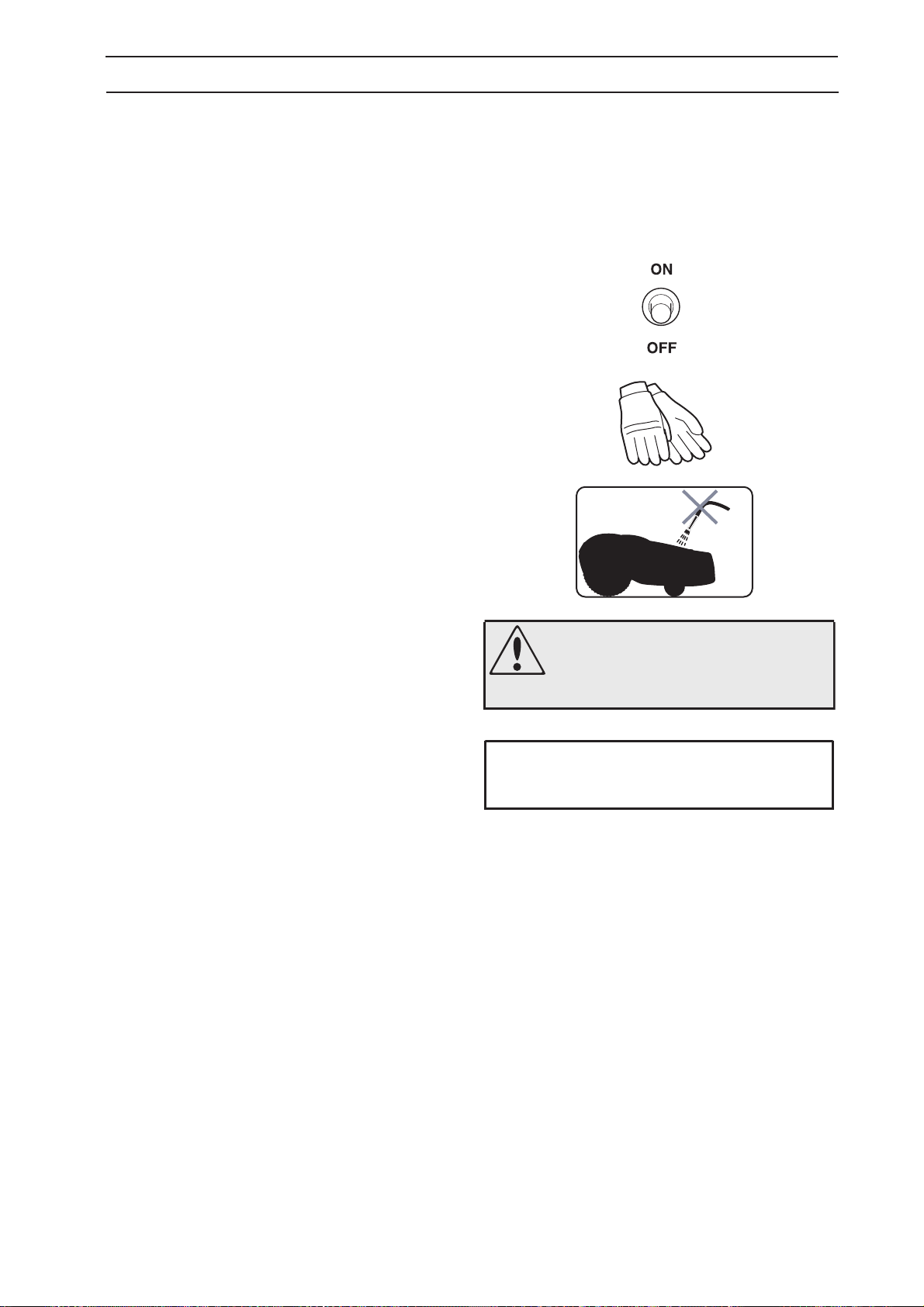
• Inspection and/or maintenance must be carried
out with the main switch set to OFF .
• Always wear protective gloves when working
with the mower’s underframe.
• Never use a high-pressure washer or even
running water to clean Automower™.
• A warning box indicates a risk of personal injury
exist, especially when the stated instructions are
not followed.
• An information box indicates a risk of material
damage exist, especially when the stated
instructions are not followed. The box is also
used where there is a risk of user error.
WARNING
Xxxxxx xxxxx xxxx xxxx xxxxx xxx.
IMPORTANT INFORMATION
Xxxxxx xxxxx xxxx xxxx xxxxx xxx.
English - 7

1. INTRODUCTION AND SAFETY
1.4 Safety instructions
Use
• Please read the Operator's Manual carefully and
make sure you understand the instructions
before using Automower™.
• It is not permitted to modify the original design of
Automower™. All modifications are made at your
own risk.
• Check that there are no stones, branches, tools,
toys or other objects on the lawn that can
damage the blades and cause the mower to
stop.
• Start Automower™ according to the instructions.
When the main switch is in the ON position;
make sure you keep your hands and feet away
from the rotating blades. Never put your hands
and feet under the mower.
• Never lift up Automower™ or carry it around
when the main switch is in the ON position.
• Do not let persons who do not know how
Automower™ works and behaves use the mower.
• Never use Automower™ if persons, especially
children, or pets, are in the immediate vicinity.
• Do not place objects on top of Automower™.
• Do not allow Automower™ to be used with a
defective blade disc or body. Neither should it be
used with defective blades, screws, nuts or cables.
• Do not use Automower™ if the main switch does
not work.
• Always switch off Automower™ using the main
switch when you do not intend to use the mower.
Automower™ can only start when the main switch
is moved to the ON position and the correct PIN
code has been entered.
• Automower™ must never be used at the same
time as a sprinkler.
• Husqvarna AB does not guarantee full
compatibility between Automower™ and other
types of wireless systems such as remote
controls, radio transmitters, buried electric animal
fencing or similar.
8 - English
1. INTRODUCTION AND SAFETY
Transport
The original packaging should be used when
transporting Automower™ over long distances.
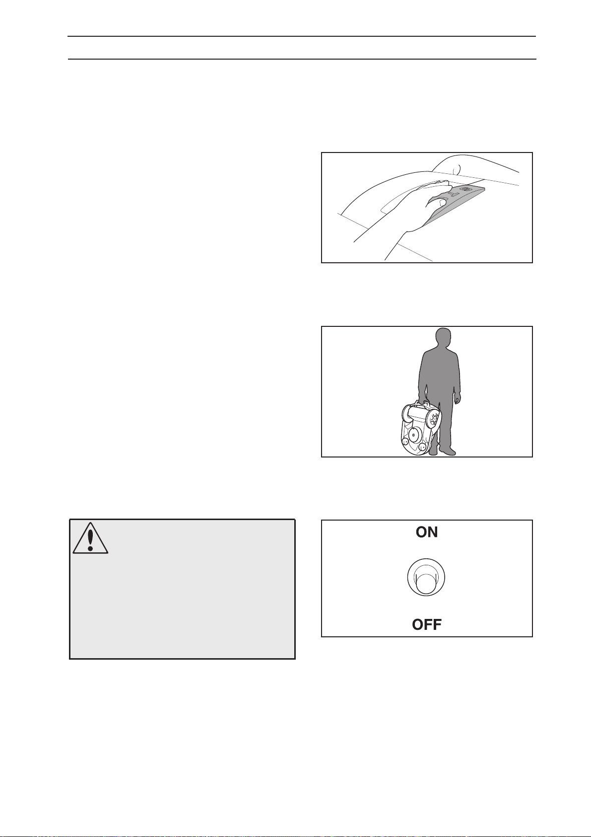
To safely move from or within the working area:
1. Press the STOP button to stop the mower.
2. Move the main switch to the OFF position if you
intend to carry the mower.
3. Carry the mower by the handle at the rear of the
mower. Carry the mower with the blade disc
away from the body.
Maintenance
WARNING
When the mower is turned upside
down the main switch must always
be set to the OFF position.
The main switch should be set to the
OFF position during all work on the
mower’s underframe, such as
cleaning or replacing the blades.
• Inspect Automower™ each week and replace any
damaged or worn parts.
Check especially that the blades and blade disc
are not damaged. Replace all blades and screws
at the same time if necessary so that the rotating
parts are balanced, see 7. Maintenance on
page 37.
English - 9
2. PRESENTATION
2. Presentation
This chapter contains information you should be aware
of when planning the installation.
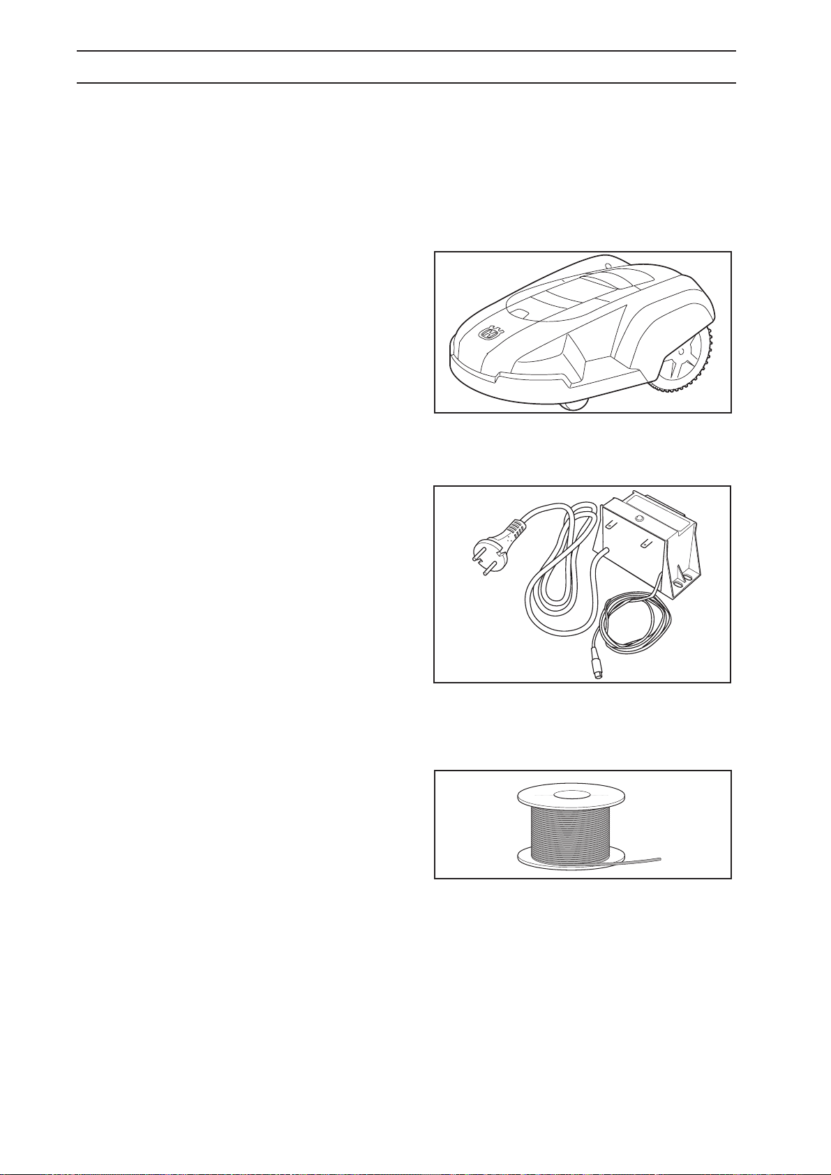
An installation of Husqvarna Automower™ comprises
three main components:
Automower™, an automatic lawn mower that mows
the lawn by moving in an irregular pattern. The mower
is powered by a maintenance-free battery.
Loop generator/charger.
The loop generator/charger has two functions:
• To send control signals along the boundary wire.
• To charge the battery in Automower™.
The loop generator/charger is connected to a 230V
(120V) wall socket via an integrated power cord and
to the mower via a 2 m (6 ft) long low voltage cable
.
Wire, laid in a loop around Automower™’s working
area. The boundary wire is laid around the edges of
the lawn and around objects and plants that the
mower must not run into.
The wire supplied with the installation is 150 m
(500 ft) long. If this is not sufficient more wire can be
purchased, with a connector, and spliced onto the
existing wire.
10 - English

2. PRESENTATION
6
2.1 Automower™, what’s what?
15
2
10
1
3
12
11
6
5
7
4
8
13
16
17
9
14
18
19
20
The numbers in the picture correspond to:
1. Cutting height adjustment cover
2. Catch button to open the cutting height adjustment
cover
3. Front wheel
4. Drive wheel
5. Body
6. Stop button
7. Indicator lamps
8. Keypad
9. Main switch
10. Handle
11. Charger contact
12. Chassis box with electronics, battery and motors
13. Skid plate
21
14. Blade disc
15. Loop wire for boundary wire
16. Connection to boundary wire
17. LED for operation check of the boundary wire
18. Loop generator/charger
19. Staples
20. Connector for the loop wire
21. Measurement gauge for help when installing the
boundary wire
22. Solderless coupler for the loop wire
23. Operator’s Manual
22
23
English - 11

2. PRESENTATION
2.2 Function of Automower™
Capacity
Automower™ is recommended for lawns up to 500 m
(0.15 acre). The size of the working area the mower
can handle depends on how much it is used. The
larger the lawn the more occasions per week
Automower™ can work.
How large an area is mown per hour depends primarily
on the condition of the blades and the type of grass,
growth rate and humidity. The shape of the garden is
also significant. If the garden mainly consists of open
lawns, Automower™ can mow more per hour than if
the garden consists of several small lawns separated
by trees, flower beds and passages.
2
Automower™ must work several times a week for the
lawn to be mown properly. If the grass is too tall when
the mower starts to work the result will be poor. Neither
is it advisable to allow Automower™ to mow too often.
If the mower works too much, the lawn will appear
trampled down. How many times, and how long, the
mower should work per week, is determined among
others by the shape of the lawn, the length of the grass
and the condition of the blades. If the lawn is 300 m
(0.07 acre) it is recommended to let Automower™
mow three times a week. Match the use of
Automower™ to your garden.
How long Automower™ mows and recharges can vary
depending on, among others, the ambient
temperature. Up to about 25°C (77 °F) a fully charged
Automower™ mows for approximately 2 - 3 hours,
depending on the age of the battery and the thickness
of the grass. It takes around 4 - 5 hours to fully charge
the battery in the mower. The mowing time drops
successively above 25°C (77 °F).
If required, the mowing time can be increased by
installing an additional battery. The mowing time then
increases to approx. 4 - 6 hours. This also means that
the charging time increases to approx. 5 - 7 hours.
Please contact your dealer for more information.
2
12 - English
2. PRESENTATION
Mowing technique
The mowing system used by Automower™ is based
on an effective and energy efficient principle. Unlike
normal lawn mowers, Automower™ cuts the grass
instead of striking it off.
We recommend you allow Automower™ to mainly
mow in dry weather to obtain the best possible result.
Automower™ can even mow in the rain, however, wet
grass easily collects on the mower and the risk of
slipping on steep slopes is greater. To keep the drive
wheels clean and thus increase traction, use
Automower™ wheel brushes (505 13 27-01).
If there is a risk of thunder, the 230V (120V) plug
should be removed.
The blades must be in good condition to obtain the
best mowing result. In order to keep the blades sharp
for as long as possible it is important to keep the lawn
free from branches, small stones and other objects.
English - 13
2. PRESENTATION
Working method
Automower™ automatically mows the lawn.
Automower™ automatically mows the lawn. When the
battery is discharged the mower stops on the lawn, and
you need to carry it to the loop generator/charger for
charging.
When Automower™ body hits an obstacle, the mower
reverses and selects a new direction.
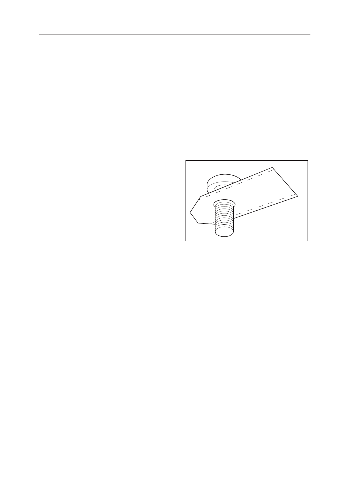
Two sensors, at the front and back on Automower™,
sense when the mower approaches the boundary
wire. Automower™ overruns the wire by up to
27 centimeters (11") before it turns.
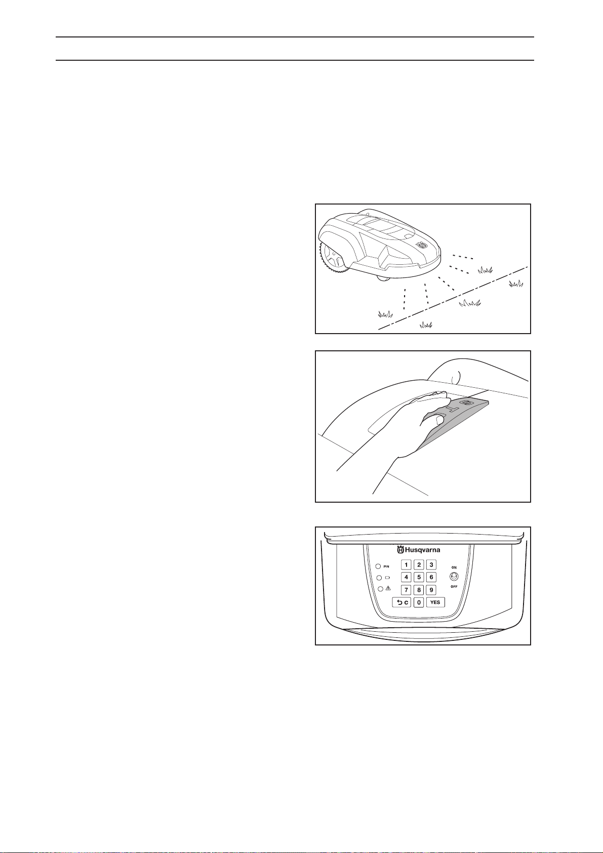
The STOP button on the top of Automower™ is
mainly used to stop the mower when it’s running.
When the STOP button is pressed a cover opens,
behind which there is a control panel. The STOP
button remains depressed until the cover is closed
again. This acts as start inhibitor.
You start the mower via the control panel on top of
Automower™. Open the control panel cover by
pressing down the STOP button.
A four digit PIN code must be chosen and entered
when the main switch is set in the ON position for the
first time. (see page 31).
The chosen PIN code must then be entered each
time the mower is started. If the mower does not start
within 20 seconds the PIN code must be re-entered
until the mower starts. Slide shut the cover to start the
mower after the PIN code has been entered.
Automower™ can, to save energy, enter sleep mode.
The indicator lamps on the control panel are then
turned off completely.
The sleep mode is activated 25 minutes after the
STOP button has been pressed and then not reset to
the operating mode. Automower™ is then activated by
switching the main switch off and on.
The sleep mode can also be activated in the event of a
fault occurring during mowing or charging and which is
not rectified within 25 minutes. Automower™ is then
activated by pressing the STOP button.
14 - English

2. PRESENTATION
Movement pattern
The mower’s movement pattern is irregular and is
determined by Automower™ itself. A movement
pattern is never repeated. This mowing system
means the lawn is mown equally without any mowing
lines.
2.3 One Automower™ in several
gardens
One Automower™ can easily be used for more than
one garden, where each garden has its own loop
generator/charger and boundary wire.
Contact your dealer for further information.
English - 15
3. INSTALLATION
3. Installation
This chapter describes how you install Husqvarna
Automower™. Before starting the installation read the
previous chapter
Read the whole of this chapter too before starting the
installation. How the installation is made also affects how well
Automower™ will work. It is therefore important to plan the
installation carefully.
Planning is simplified if you make a sketch of the working
area, including all obstacles. This makes it easier to see how
the boundary wire should ideally be placed. Draw how the
boundary wire is to be routed on the sketch.
Carry out the installation in the following steps:
3.1 Preparations.
3.2 Installation of the loop generator/charger.
3.3 Charging the battery.
3.4 Installation of the boundary wire.
3.5 Connecting the boundary wire.
3.6 Checking the installation.
3.7 Linking the Automower™ to the loop generator/charger.
In order to carry out a complete start-up of Automower™ the
loop generator/charger and boundary wire must be
connected and the mower linked to the loop
generator/charger. If you would like to start the mower
without having completed the full boundary installation, you
can connect a temporary short loop around the mower.
2. Presentation.
3.1 Preparations
1. If the lawn in the proposed working area is taller than
10 cm (4"), mow it using a normal lawn mower. Then
collect the clippings.
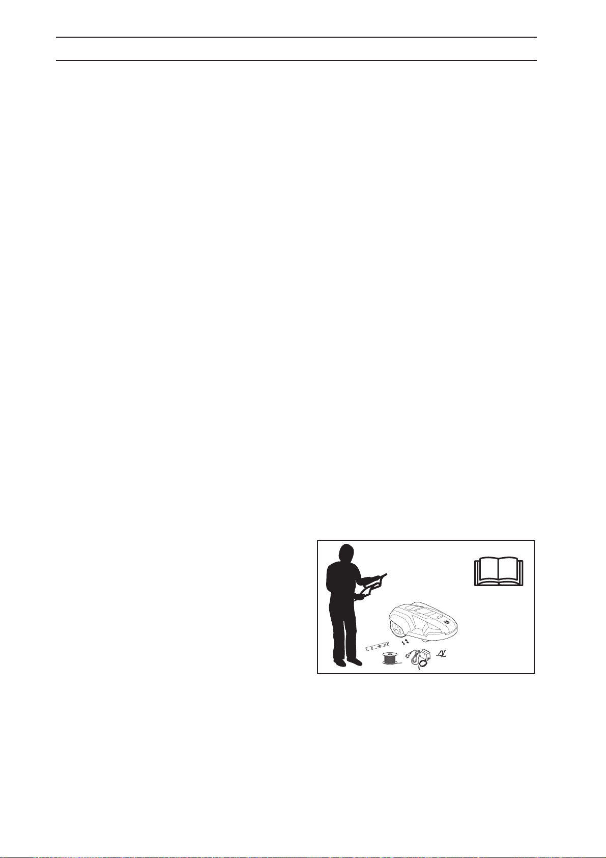
2. Read carefully through all the steps before the
installation.
3. Check that all parts for the installation are included:
The numbers in brackets refer to the detail diagram
2.1 Automower™, what’s what? on page 11.
• Operator’s Manual (23)
• Automower™
• Loop generator/charger (18)
• Loop wire for the boundary wire (15)
• Staples (19)
• Connector for the loop wire (20)
• Measurement gauge (21)
• Solderless coupler for the loop wire (22)
During installation you will also need: A hammer to knock the
staples into the ground, combination pliers, and a straight
spade if the boundary wire is to be buried.
16 - English
 Loading...