

Husqvarna 111750 - HCS1372 User Manual
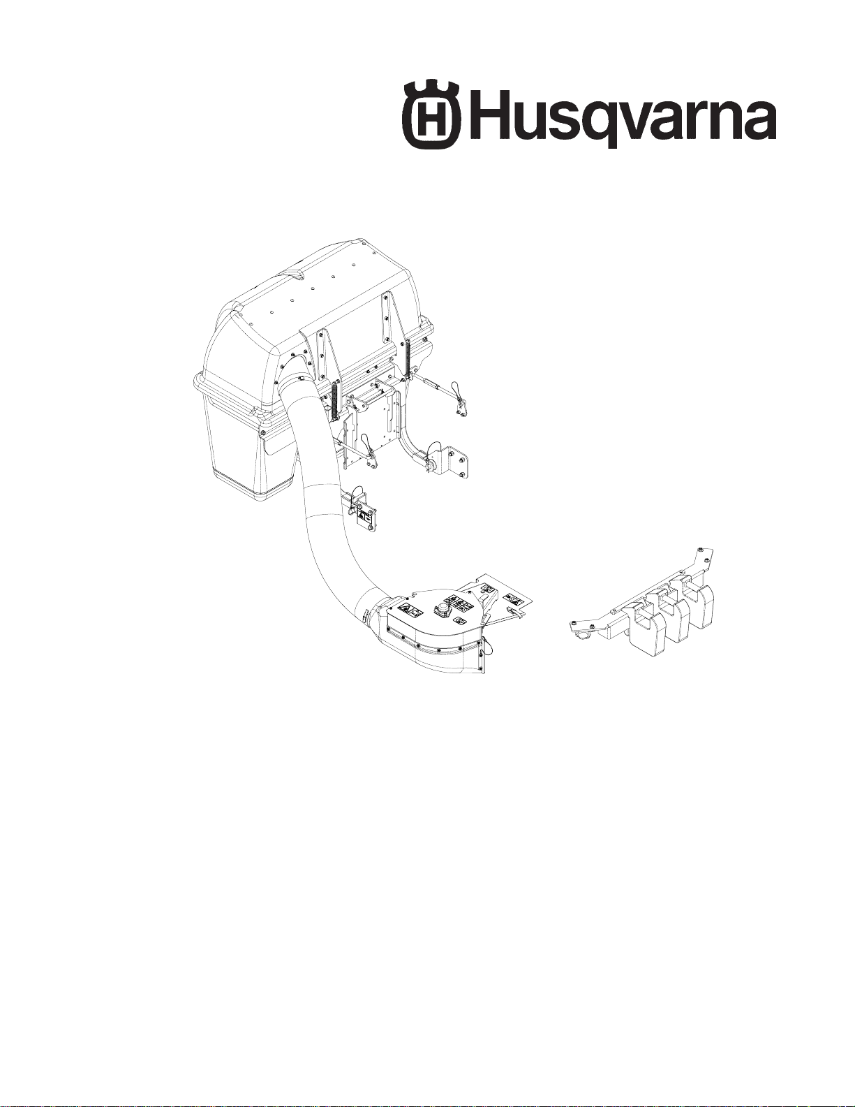
Collection System
Operators Manual
Models:
Parts Manual
Please read these instructions carefully and make
sure you understand them before using the machine.
MANUAL NO. 5391 11758 REV 01 (03/31/05)
111750 / HCS1372

©2005 Husqvarna. All Rights Reserved.
Beatrice, NE. Printed in U.S.A.
2

INDEX
Operators Guide
Features and Controls.............................................................. 4
General Information ................................................................. 5
Safety Procedures.................................................................... 5
Unpacking Instructions............................................................. 7
Assembly Instructions .............................................................. 7
Collection System.............................................................. 7
Blower/Drive Kit ............................................................... 11
Operating the Collection System........................................ 12
Maintenance and Service Instructions
Transport................................................................................ 13
Cleaning and Washing ........................................................... 13
Storage................................................................................... 13
Preventative Maintenance Schedule...................................... 13
Caring for Vacuum Hoses ...................................................... 14
Cleaning Poly Mesh ............................................................... 14
Caring for Bags ...................................................................... 14
Troubleshooting Guide........................................................... 15
Replacement Parts
Hood Assembly ...................................................................... 18
Hitch Assembly....................................................................... 19
Blower Assembly.................................................................... 20
Weight Kit............................................................................... 22
Mounting Kit ........................................................................... 23
Bag Assembly ........................................................................ 24
Drive Kit.................................................................................. 25
Parts Description.................................................................... 26
WARNING: Engine exhaust, some of its constituents, and certain vehicle components con-
tain or emit chemicals known to the State of California to cause cancer and birth defects or
other reproductive harm.
3
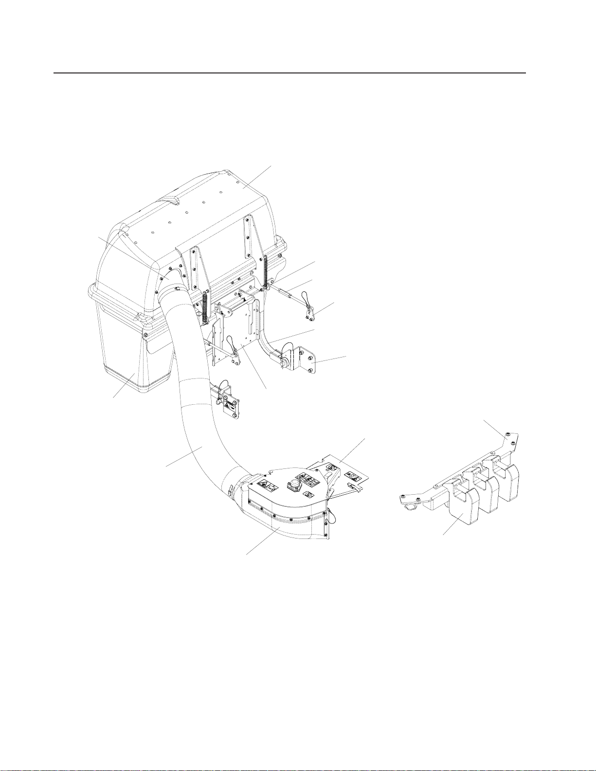
INLET
FEATURES & CONTROLS
HOOD
LATCH
SUPPORT LINKAGE
SUPPORT BR ACKET
HITCH
BAG
HITCH BRACKET
REAR GUARD
WEIGHT BA R
DRIVE KIT
HOSE
CAST WEIGHT
BLOWER ASSEMBLY
NOTE: Your Front Weight Bar may look different from those shown in this diagram.
4

SAFETY RULES
General Information
This manual will assist you in the safe operation
and proper maintenance of your Husqvarna
equipment. Read it thoroughly before attempting
to operate the machine. Call your dealer or
Husqvarna if additional information is required.
The following safety symbols are used throughout
the manual to alert you to information about unsafe
actions or situations:
DANGER indicates immediate hazards that
may result in severe injury or death.
WARNING indicates unsafe actions or
situations that may cause severe injury,
death, and/or major equipment or property
damage.
CAUTION indicates unsafe actions or
situations that may cause injury and/or
minor equipment or property damage.
This equipment should not be modified without the
manufacturer’s prior written authorization. Doing
so may not only affect the equipments’
performance and durability , but also create safety
hazards for the operator and the surroundings.
Warranty will be void if changes are made to the
equipment without the manufacturer’s prior written
authorization.
Safety Procedures
1 - Training:
• Read the Operator’s manual. If the operator(s)
or mechanic(s) can not read English it is the
owner’s responsibility to explain this material to
them.
• Become familiar with the safe operation of the
equipment, operator’s controls, and safety
signs.
• All operators and mechanics should be trained.
The owner is responsible for training the users.
• Never let children or untrained people operate
or service the equipment. Local regulations may
restrict the age of the operator.
• The owner/user can prevent and is responsible
for accidents or injuries occurring to themselves,
other people, and/or property.
2 - Preparation:
• Wear appropriate clothing including hard hat,
safety glasses and ear protection. Long hair,
loose clothing or jewelry may get tangled in
moving parts.
• Inspect the area where the equipment is to be
used and remove all objects such as rocks, toys
and wire which can be thrown by the machine.
• Use extra care when handling gasoline and
other fuels. They are flammable and vapors
are explosive. Use only an approved container.
Never remove gas cap or add fuel with engine
running. Allow engine to cool before refueling.
Do not smoke while fueling or operating
equipment. Never refuel or drain the machine
indoors.
• Check that operator’s controls, safety switches,
hoses, and shields are securely attached and
functioning properly. Do not operate unless
they are functioning properly .
5

SAFETY RULES
3 - Operation
• Never run an engine in an enclosed area.
• Only operate in good light, keeping away from
holes and hidden hazards.
• Slow down and use extra care on hillsides.
Make turns gradually and at slow speed. Do
not operate across the sides of slopes. Operate
up and down slopes only. Do not operate on
steep slopes.
• Turf conditions can affect the machine’ s stability .
Do not operate on wet grass where traction may
be reduced.
• Do not change the engine governor setting or
overspeed the engine.
• Stop equipment and inspect vacuum impeller
and hoses after striking objects or if an abnormal
vibration occurs. Make necessary repairs before
resuming operations.
• Look behind and down before backing up to
ensure a clear path.
• Slow down and use caution when making turns
and crossing roads and sidewalks. Stop vacuum
and mower blades if not mowing.
• Do not operate machine under the influence of
alcohol or drugs.
• Use care when loading or unloading the machine
into a trailer or truck.
• Use care when approaching blind corners,
shrubs, trees, or other objects that may obscure
vision.
4 - Maintenance and Storage:
• Stop engine and disconnect spark plug wire.
Wait for all movement to stop before adjusting,
cleaning, or repairing.
• Clean grass and debris from muffler and engine
to help prevent fires. Clean up oil or fuel
spillage.
• Let engine cool before storing and do not store
near sparks or open flame.
• Shut off fuel while storing. Do not store fuel
near flames or drain indoors.
• Never allow untrained personnel to service
machine.
• Keep hands and feet away from moving parts.
If possible, do not make adjustments with the
engine running.
• Keep all parts in good working condition and all
hardware tightened. Replace all worn or
damaged decals.
6
ASSEMBLY
Unpacking Instructions
1. Cut plastic tie securing the hitch to the crate top.
2. Remove the top of the crate.
3. Remove the plastic bag.
4. Remove the hose.
5. Remove the sides and ends of the crate.
6. Remove the mounting kit and drive kit boxs from the corner of the crate.
7. Cut the two plastic ties that secure the hitch assembly to the pallet. Remove the hitch assembly .
8. Cut the two plastic ties that secure the back of the hood, and the two that secure the front of the
hood. Remove the hood assembly.
9. Cut and two plastic ties that secure the weight bar to the pallet. Remove the weight bar.
10. Cut the two plastic ties that secure the blower assembly to the pallet. Remove the blower assembly .
11. Remove the 1 x 4 that secures the cast weights to the pallet. Remove the weights.
1
Assembly Instructions
Collection System
Tools Required:
Ratchet
Torque Wrench
1/2" Wrench
1/2" Socket
9/16" Wrench
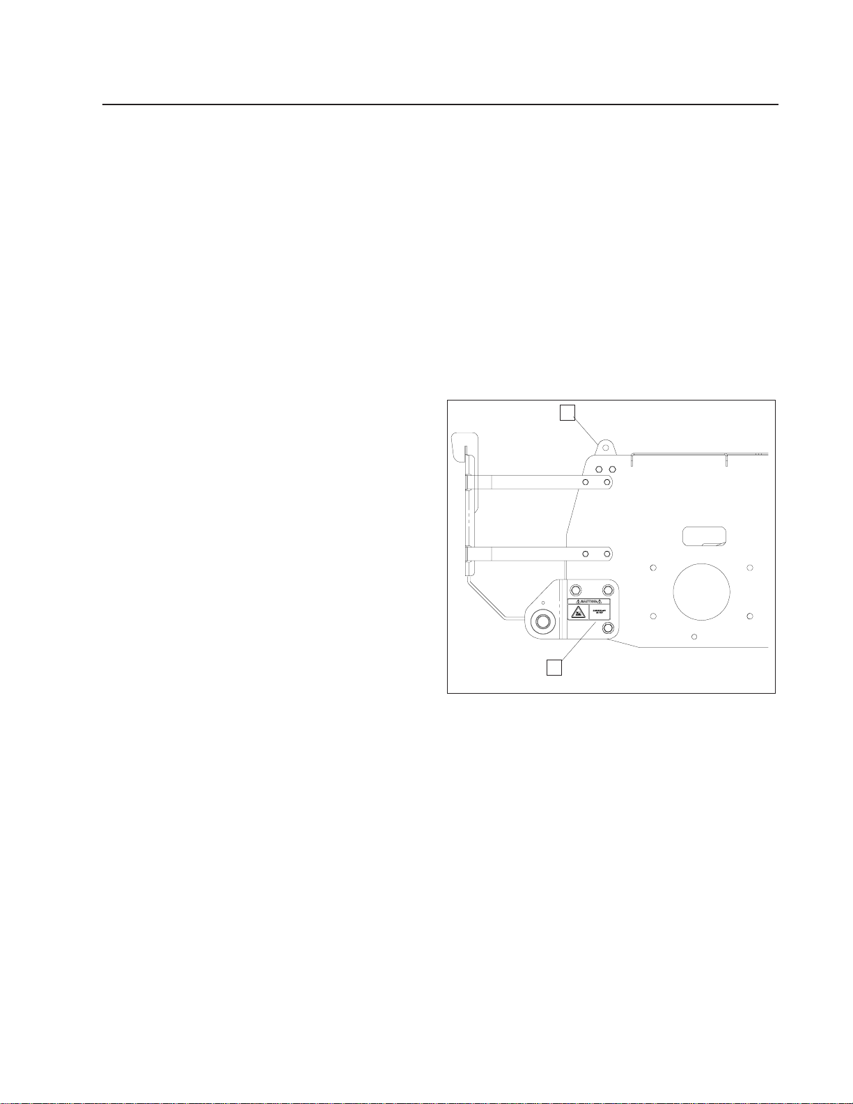
1. Open the mounting kit box and remove all of
the components.
2. Place the support bracket on the frame and
secure with (2) 990563, 3/8 x 1 bolts and (2)
976979, 3/8 nyloc nuts. Figure 1.
3. Place the hitch brackets on the frame and
secure with (3) 990622, 1/2 x 1 1/4 bolts and
(3) 101331, 1/2 nyloc nuts. Figure 1.
9/16" Socket
5/8" Socket
(2) 3/4" Wrench
3/4" Socket
Flat Screw Driver
2
FIGURE 1
1. SUPPORT BRACKET
2. HITCH BRACKET
7
ASSEMBLY
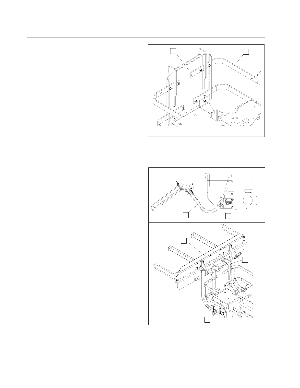
4. Remove the (10) 5/16 carriage bolts that
secure the standard rear guard to the straps
and skid plates. Remove the standard rear
guard. Replace with the collection rear
guard, and secure with the carriage bolts that
were just removed. Figure 2.
5. Place the hitch assembly on the ground
behind the mower. Place the (2) hitch pins
thru the hitch and the hitch brackets. Secure
the hitch pins with the (2) hairpins that are
secured with the (2) lanyards. Figure 3.
1
2
FIGURE 2
1. REAR GUARD
2. STRAP
2
1
3
6. Move to the rear of the hitch assembly and
pick it up towards the rear guard. The latch
will hook over the top of the rear guard.
Figure 3.
1
4
2
3
FIGURE 3
1. HITCH ASSEMBLY
2. LANY ARD
3. HITCH PIN
4. LATCH
8
ASSEMBLY
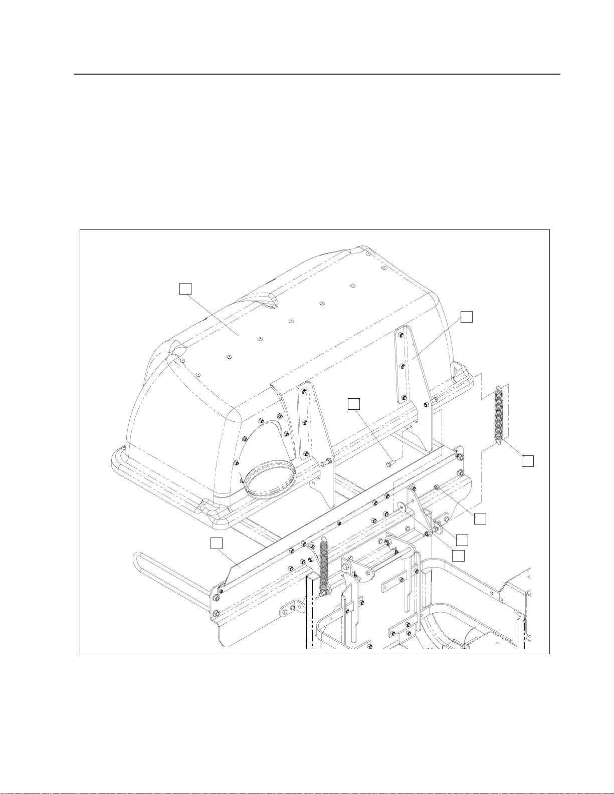
7. Place the hood assembly on to the hitch
assembly . Place both hood hinges between
the upper hitch mounts on the hitch assembly .
Be sure that the rubber seal is on the inside
of the hood. Place the (2) friction washers
between the hood hinge and the upper hitch
mount. Place (2)990563, 3/8 x 1 bolt thru the
hinge and mount. Secure with (2) 976979,
3/8 nyloc nut. Figure 4.
1
8. Open the hood and secure the (2) springs
to the bolts on the hood assembly and the
hitch assembly. Figure 4.
2
5
1. HOOD ASSEMBLY
2. HOOD HINGE
3. 3/8 X 1 BOLT
4. SPRING
3
4
6
7
8
FIGURE 4
5. RUBBER SEAL
6. 3/8 NYLOC NUT
7. UPPER HITCH MOUNT
8. HITCH PIN
9
ASSEMBLY
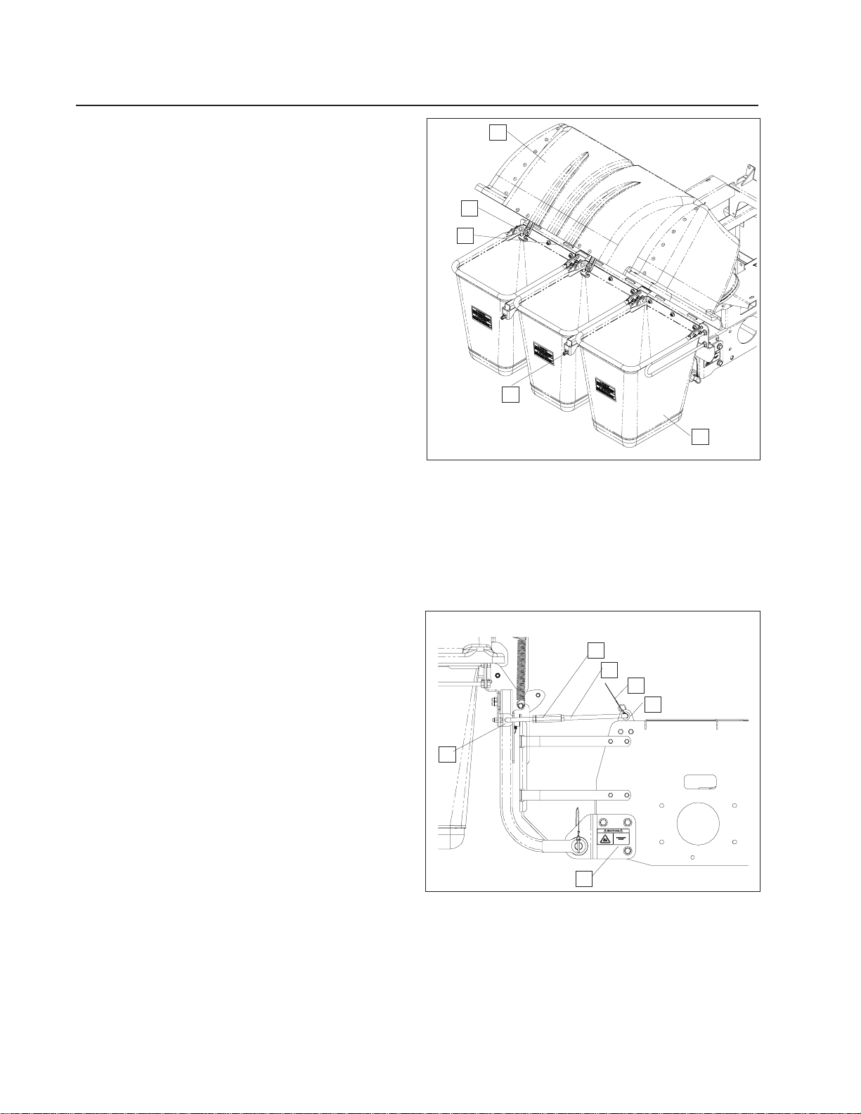
9. With the hood open, secure the (3) bags in
place. The back of the bags will hook over
the mounting tabs on the hitch assembly.
Figure 5.
10. Close the hood, and latch the draw latch over
the draw latch keeper on the hitch assembly .
Figure 5.
11. Install the (2) linkage assemblies to the (2)
support brackets on hitch assembly and the
(2) support brackets on the frame. The
shorter linkage connects to the support
bracket on the hitch assembly. Figure 6.
NOTE: The linkage assemblies may need to be
adjusted. Using (2) 3/4" wrenches, loosen the 1/2"
jam nut on the longer linkage. Turn the turnbuckle
in the appropriate direction to shorten the linkage
assembly. Turn until the slop is taken out of the
linkages. Tighten the jam nut against the
turnbuckle.
1
2
3
4
5
FIGURE 5
1. HOOD ASSEMBLY
2. DRAW LATCH
3. MOUNT TABS
4. DRAW LATCH KEEPER
5. BAG
2
3
4
5
1
12. Secure the front of the linkage assemblies
using the hairpin secured by the lanyard.
Secure the rear of the linkages using the (2)
990654, cotter pins provided. Figure 6.
13. Place the hose on the inlet and secure with
the hose clamp.
6
FIGURE 6
1. SUPPORT BRACKET
2. TURNBUCKLE
3. LINKAGE ASSEMBLY
4. LANYARD
5. SUPPORT BRACKET
6. HITCH BRACKET
10
 Loading...