

Page 1
EZ WIRE INSTALLATION INSTRUCTIONS
1
Page 2

INSTALLATION RECOMMENDATIONS
•
Floor Anchors (part #H5814 in post kit. ½” x 4
-
1/4”) Post Shims (Part #H5820 in post kit) INCLUDED
•
Floor Anchors (part #H5814 in post kit. ½” x 4
-
1/4”) Post Shims (Part #H5820 in post kit) INCLUDED
Tools Recommended:
• Safety ladder (most jobs too tall to reach from floor)
• Carpenter Level
• Chalk line
Tools Required
• 1/2” Masonry bit (drill holes in floor for post)
• 1/2” wrench or socket (screws for door to the post)
• ¾” wrench or socket (for anchor bolts)
• Small hammer (to insert drive pins)
Parts Recommended:
• Drill Bits (various)
• Tape measure
• Safety Items (hardhat, gloves, safety glasses & steel toe work shoes); remove jewelry
Prior to installation:
• Prior to beginning installation please check bill of lading to make sure that you have all the parts required for the assembly
• Make sure that the installation area is clear of all obstructions
• Read thoroughly all the instructions pertinent to your installation
• The following installation instructions should be used as a guide for installing Husky Rack & Wire EZ WIRE products. Good common
sense and appropriate safety precautions must be used during installations. The product may be unstable during installation;
temporary bracing should be used until all hardware is tightened and the product is properly anchored to the floor. Permanent field
bracing (NOT SUPPLIED) may be installed. Call Factory if installation help is needed. Installation problems arising from job site
conditions should be referred to a professional installer. Refer product assembly questions to Husky Rack & Wire. 800-438-5629.
• D
O NOT CLIMB FENCE DURING OR AFTER INSTALLATION
2
Page 3
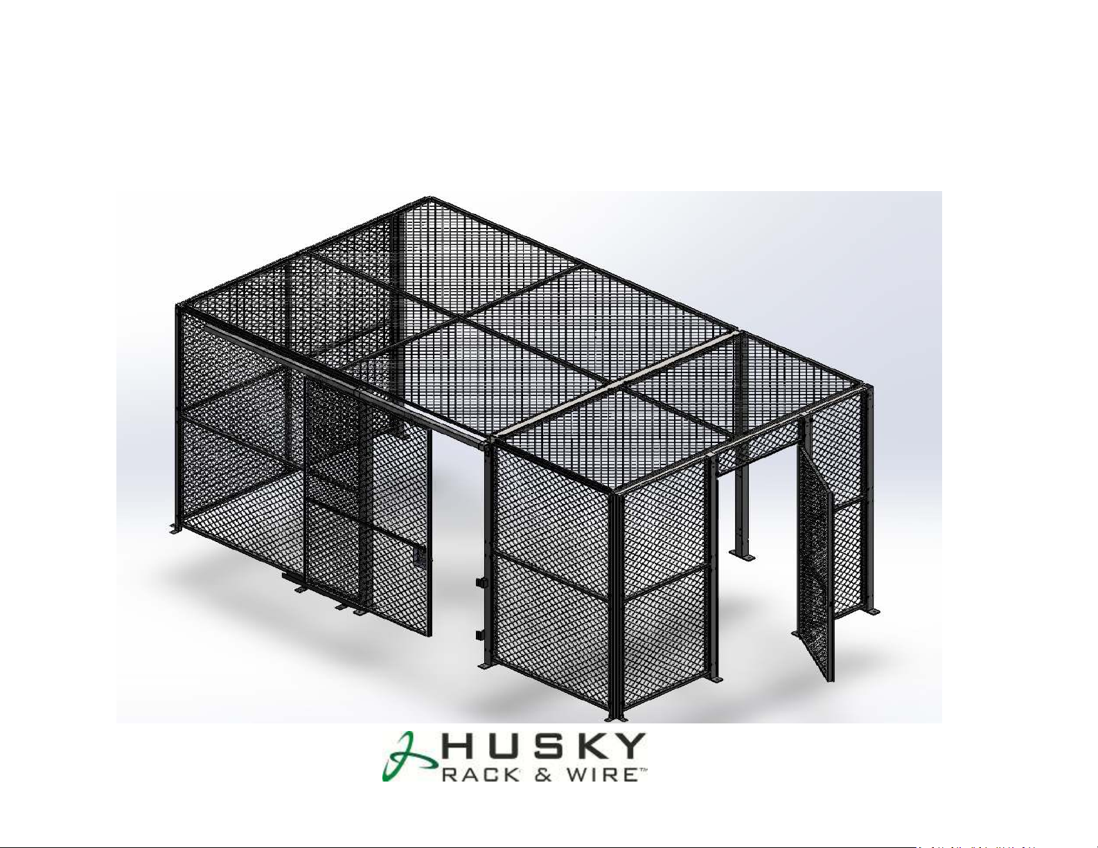
PANEL/POST ARRANGEMENTS
inside of the cage.
inside of the cage.
• Use a chalk-line to mark the partition
runs on the floor.
• Starting with a Line Post, lag the post
to the floor using two floor anchors.
(the line post is 2 ½” square tube
with 2 ½” x 7 ½” footplate welded to
it). Make sure the slots are facing
• Stand up another Line post at a
distance of width of the panel to be
installed. (Distance between in the
post = Nominal width of the Panel – 2
3/8”). For 8’ panel, distance between
the post is 96”-2 3/8” = 93 5/8”
• Pick up the panel and install the
hooks in the slots of the line post.
Install bottom panel first.
• Install top panel and fasten to the
post using drive pins.
• EZ Wire panels are installed from the inside of the cage.
3
Page 4
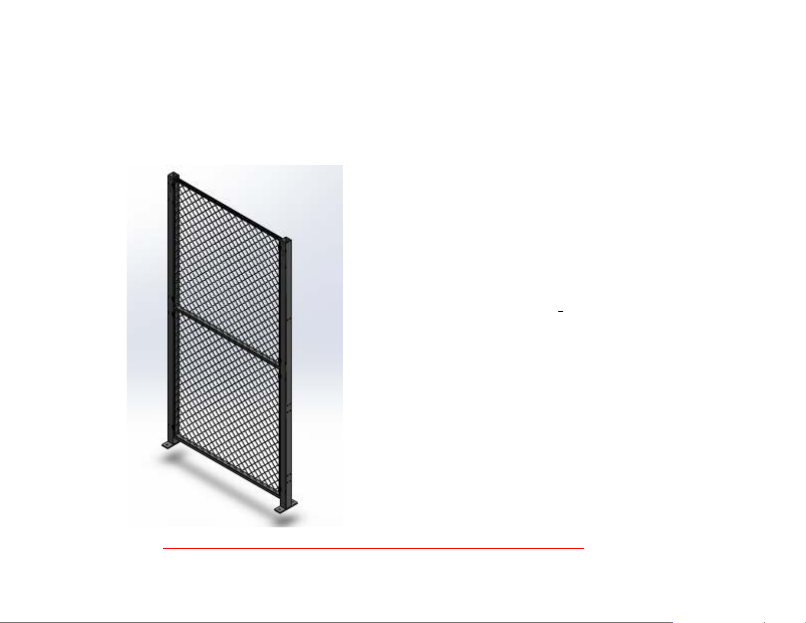
PANEL/POST ARRANGEMENTS
Put drive pin into the
Put drive pin into the
• Install one drive pin per
hook for maximum
security.
•
hole
• Tap on the extended pin
Inside of
the cage
DRIVE
PIN
using hammer until it is
flush with the cap part
of the drive pin.
4
Page 5
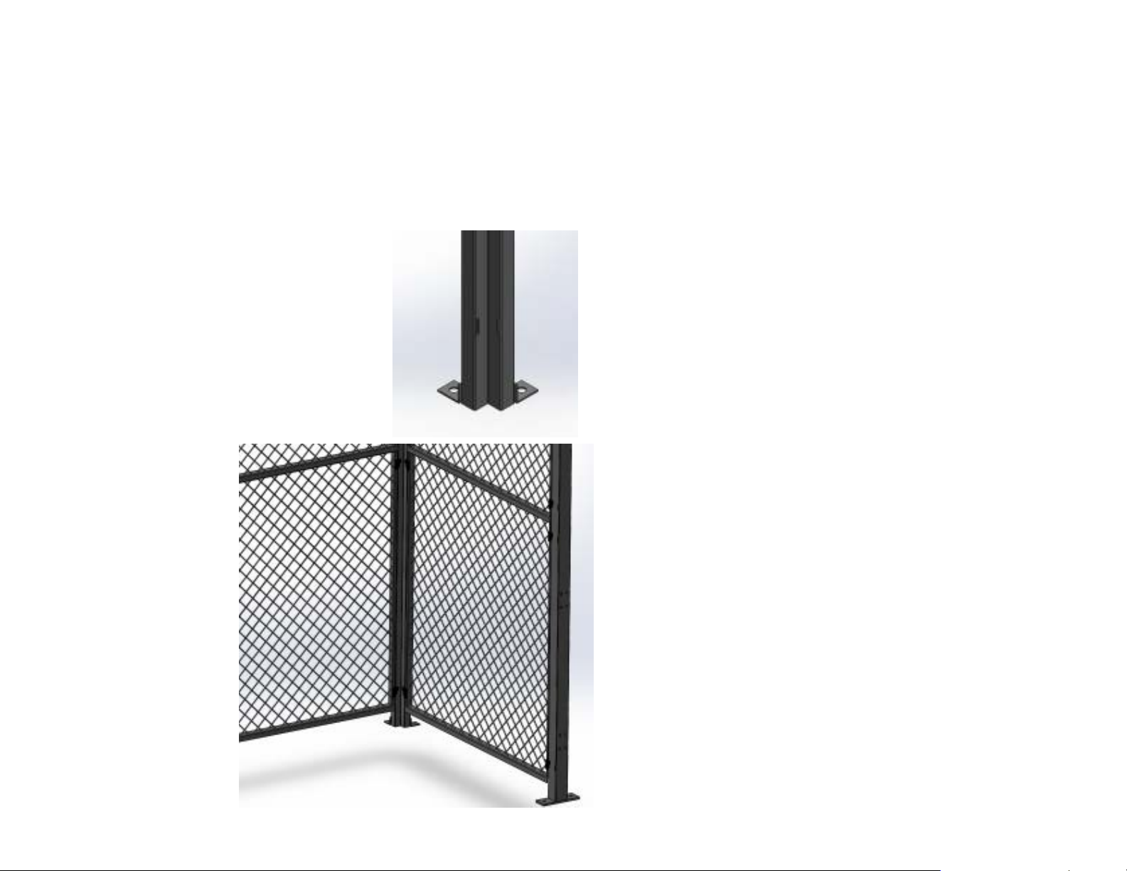
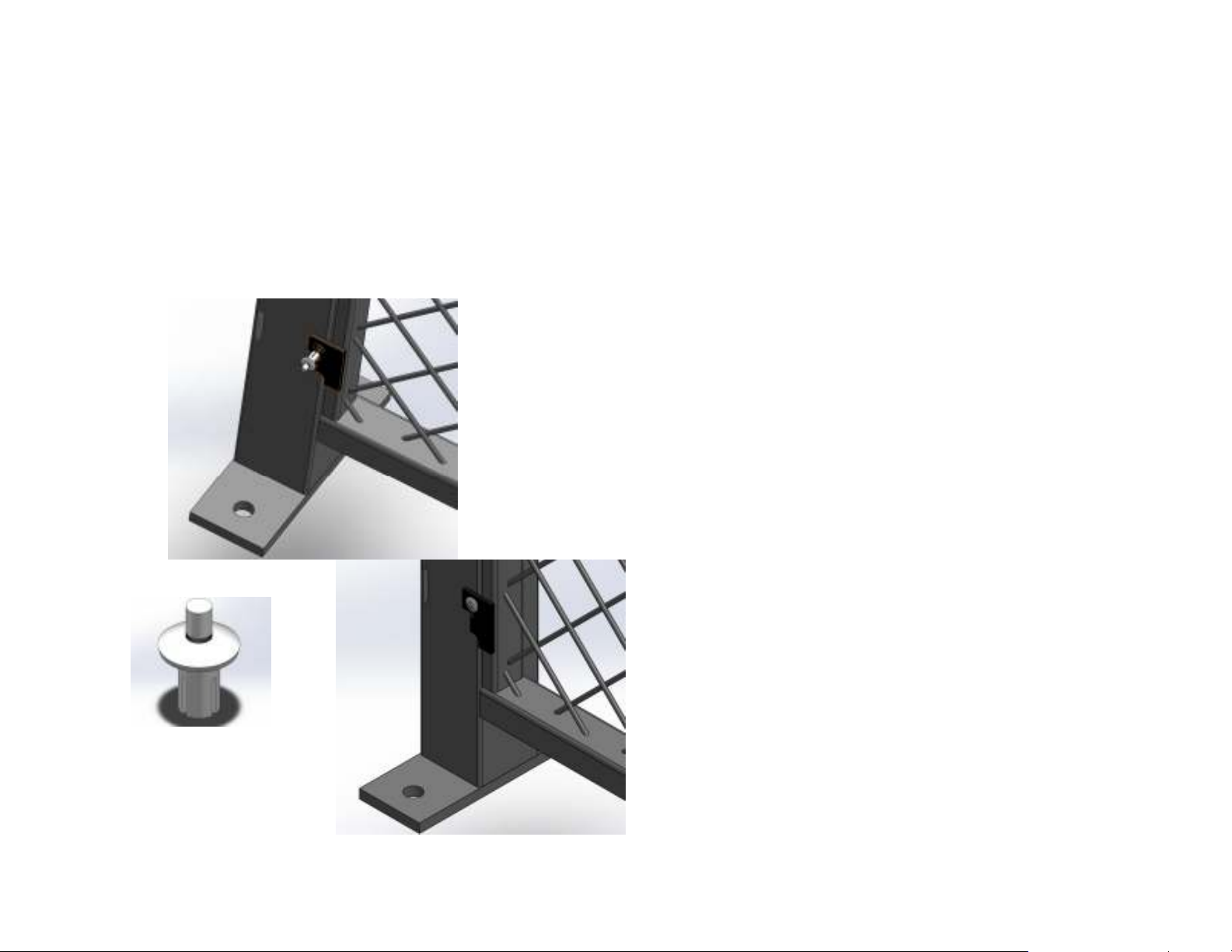
CORNER POST APPLICATION
Corner post can be
Corner post can be
• Corner post are used for
turning corner at 90
degrees.
•
installed as an Inside
Corner or Outside
Corner.
Inside
Corner
5
Page 6

Transom Panel
Strike
•
Install Transom panel first and anchor the
Strike
SINGLE SWING DOOR
• Swing doors can be installed Left/Right Hand,
Swing In or Swing Out.
• The Picture shows Hinge right Swing Out
(HRSO) door looking from outside of the
cage.
• The opening between the posts for a swing
door installation is equal to Nominal Width –
2 3/8”. (For example for 3’ door the opening
between the post is 36-2 3/8” = 33 5/8”)
Bar
line posts to the floor ensuring the opening
width at the floor equals the transom width.
• Using 5/16” x 3” Carriage Bolts (3), attach
door and strike bar to the posts.
• Install Cylinder Lock (see page…).
6
Page 7

DOUBLE SWING DOOR
is inside of the cage
HEADER BAR
• First install header bar on top
using 5/16” x 3” long carriage
bolts.
• Install door panels to the post
using 5/16” x 3” long carriage
bolts. Make sure the cane bolt
OPERATION: Close the door panel
with the cane bolt first against
the header bar and then turn
the cane bolt handle. The rod
will go behind the header bar
and will secure the door in
place. Close the door panel
with lock plate against the
other door panel.
7
Page 8

SINGLE SLIDE DOOR
•
Install the Track Bracket to the post on either side of
TRACK
BRACKET
LATCH
RECEIVER
OVERHEAD
TRACK
• Slide doors can be installed inside or outside .
• The inside distance between the posts is measuring
width of the door – 2 ½”. (If a panel is installed
above the door, the opening between the posts will
be the width of the panel)
• Install lock in the door first.
• Attach two 4-wheel trolley per door in the ½”
diameter holes provided.
• Using 5/16” x 3” carriage bolts and nuts, install
Latch Receiver and Bottom Slam.
the door opening using 5/16” x 3 ½” carriage bolts
and nuts. A third Track bracket can be installed on
the post or to the panel using Panel Kit Plate.
• Install the Door Track in the Track Brackets. Secure
the Track by tightening ¼” screw provided.
• Slide the door trolleys into the overhead Track.
• Install a track bumper as a keeper for the door
Trolleys.
• Attach the Bottom Guide as shown.
BOTTOM SLAM
BOTTOM
GUIDE
8
Page 9

SINGLE SLIDE DOOR
SLIDE LOCK
LATCH RECEIVER
BOTTOM SLAM
TRACK BRACKET 4-WHEEL TROLLEY
BOTTOM GUIDE
9
Page 10

SINGLE SLIDE DOOR
supplied to attach track
Track
Panel Kit
Plate with
hanger
• If the track is not long
enough to reach the
next post, Panel Kit
Plate with Hardware is
hanger to the panel.
Hardware
10
Page 11

DOUBLE SLIDE DOOR
11
Page 12

INSTALLATION OF CEILING END SUPPORT
installed cage, and secure
• Ceiling End Supports are
installed on top of the wall
panels.
CEILING END
SUPPORT
• To install, lay them on the
top of the wall panels of an
using ¼” self drilling screws.
Holes of the Ceiling End
Support should line up with
the holes on the top of the
wall panels. If not, drill
holes on top of the wall
panels.
12
Page 13

INSTALLATION OF CEILING SUPPORT TUBE
Support Tube, drop it
• Ceiling support tube is
made out of 2 ½” square
tubes with brackets
welded at both ends.
• To install the Ceiling
over the two line post of
the installed cage and
secure with self drilling
screws.
• Install panels and secure
them using drive pins
13
Page 14

TERMS AND CONDITIONS
Husky Rack and Wire
product or, in the event that this
6146 Denver Industrial Park Rd, Denver NC 28037
Phone: 704-483-1900/ Fax: 704-483-1911
productinfo@huskyrackandwire.com
• It is the intent of Husky Rack and Wire
that any product received by our
Customers fully meets their
expectations.
• Husky Rack and Wire product is
Marketed and Distributed by a number
of pre-qualified Distributor
organizations around the world. If you
have any questions about the
applications or installation of your
product is received by you in a form
you believe to be sub-standard or
below expectations, please contact the
Distributor responsible for specifying
and supplying your product.
• If for some unforeseen circumstance
the particular Distributor is unavailable
or unresponsive, we then encourage
you to call Husky Rack and Wire
Technical Support at 1-800-438-5629
or contact us at
productinfo@huskyrackandwire.com
• All parts subject to change without
notice – see
www.huskyrackandwire.com for the
latest technical data or installations.
14
Page 15

15
 Loading...