

Page 1
1.
Read all manuals
included with this
product carefully. Be
thoroughly familiar
with the controls and
the proper use of the equipment.
2. Follow all local electrical and safety
codes as well as in the US, National
Electrical Codes (NEC) and Occupational
Safety and Health Act (OSHA).
Do not operate
unit if damaged
during shipping, handling or use.
Damage may result in bursting and
cause injury or property damage.
General Safety
Information
Since the air compressor and other
components (material pump, spray
guns, filters, lubricators, hoses, etc.)
used, make up a high pressure
pumping system, the following safety
precautions must be observed at all
times:
!
WARNING
Please read and save these instructions. Read carefully before attempting to assemble, install, operate or maintain the
product described. Protect yourself and others by observing all safety information. Failure to comply with instructions could
result in personal injury and/or property damage! Retain instructions for future reference.
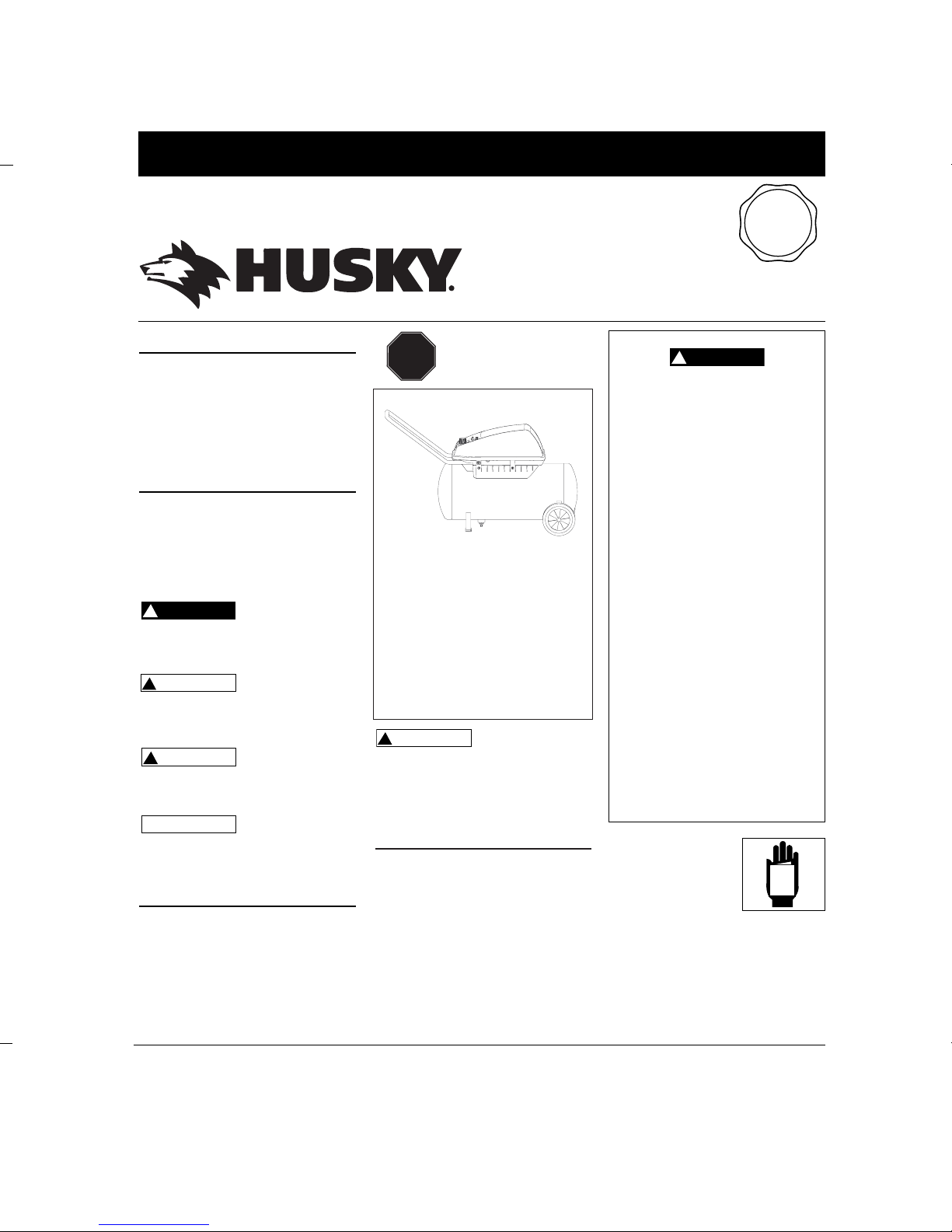
Description
Oilless compressors are designed for
do-it-yourselfers with a variety of home
and automotive jobs. These
compressors power spray guns, impact
wrenches and other tools. These units
operate without oil.
Safety Guidelines
This manual contains information that is
very important to know and understand.
This information is provided for SAFETY
and to PREVENT EQUIPMENT PROBLEMS.
To help recognize this information,
observe the following symbols.
Danger indicates
an imminently
hazardous situation which, if not
avoided, WILL result in death or serious
injury.
Warning indicates
a potentially
hazardous situation which, if not
avoided, COULD result in death or
serious injury.
C
aution indicates a
potentially
hazardous situation which, if not
avoided, MAY result in minor or
moderate injury.
Notice indicates
important
information, that if not followed, MAY
cause damage to equipment.
Unpacking
After unpacking the unit, inspect
carefully for any damage that may have
occurred during transit. Make sure to
tighten fittings, bolts, etc., before
putting unit into service. In case of
questions, damaged or missing parts,
please call 1-800-543-6400 for customer
assistance.
NOTICE
!
CAUTION
!
WARNING
!
DANGER
Operating Instructions WL6500 Series
IN605200AV 3/02
Breathable Air Warning
This compressor/pump is not
equipped and should not be used
“as is” to supply breathing quality
air. For any application of air for
human consumption, the air
compressor/pump will need to be
fitted with suitable in-line safety
and alarm equipment. This
additional equipment is necessary
to properly filter and purify the air
to meet minimal specifications for
Grade D breathing as described in
Compressed Gas Association
Commodity Specification G 7.1 1966, OSHA 29 CFR 1910. 134,
and/or Canadian Standards
Associations (CSA).
DISCLAIMER OF WARRANTIES
In the event the compressor is used
for the purpose of breathing air
application and proper in-line
safety and alarm equipment is not
simultaneously used, existing
warranties shall be voided, and
Campbell Hausfeld disclaims any
liability whatsoever for any loss,
personal injury or damage.
!
DANGER
MANUAL
STOP!
Record the Model No., Serial No. and
date of purchase located on the base
below the pump in the space below.
Model No. ____________________
Serial No. ____________________
Date of purchase _________________
Retain these numbers for future
reference.
Q
U
A
L
I
T
Y
A
S
S
U
R
A
N
C
E
P
R
O
G
R
A
M
Need
Assistance?
Call Us First!
1-800-543-8622
Oilless Air
Compressors
DO NOT RETURN THE
PRODUCT TO THE
RETAILER!
Page 2
Guía de Diagnóstico de Averías (Continuación)
Problema Posible(s) Causa(s) Acción a tomar
Exceseso de humedad
en el aire expulsado
El compresor funciona
continuamente
El compresor se
enciende y se apaga
automáticamente con
mucha frecueneia
Hay una fuga de aire en
el sistema de desfogue
del presostato
El motor gira pero no
sale aire
2
Oilless Compressors
General Safety
Information (Continued)
3. Only persons well acquainted with
these rules of safe operation should
be allowed to use the compressor.
4. Keep visitors away and NEVER allow
children in the work area.
5. Wear safety glasses and use hearing
protection when operating the
pump or unit.
6. Do not stand on or use the pump or
unit as a handhold.
7.
Before each use, inspect compressed
air system and electrical components
for signs of damage, deterioration,
weakness or leakage. Repair or
replace defective items before using.
8. Check all fasteners at frequent
intervals for proper tightness.
Motors, electrical
equipment and controls
can cause electrical arcs
that will ignite a flammable gas or
vapor. Never operate or repair in or
near a flammable gas or vapor. Never
store or spray flammable liquids or
gases in the vicinity of the compressor.
Compressor parts may
be hot even if the unit
is stopped.
9. Keep fingers away from a running
compressor; fast moving and hot
parts will cause injury and/or burns.
10. If the equipment should start to
abnormally vibrate, STOP the
engine/motor and check
immediately for the cause. Vibration
is generally a warning of trouble.
11. To reduce fire hazard, keep
engine/motor exterior free of oil,
solvent, or excessive grease.
Never remove or
attempt to adjust
safety valve. Keep safety valve free
from paint and other accumulations.
Never attempt to repair
or modify a tank!
!
DANGER
!
WARNING
!
CAUTION
!
WARNING
Welding, drilling or any other
modification will weaken the tank
resulting in damage from rupture or
explosion. Always replace worn or
damaged tanks.
Drain liquid from
tank daily.
13.
Tanks rust from moisture build-up,
which weakens the tank. Make sure
to drain tank regularly and inspect
periodically for unsafe conditions
such as rust formation and corrosion
.
14. Fast moving air will stir up dust and
debris which may be harmful. Release
air slowly when draining moisture or
depressurizing the compressor system.
SPRAYING PRECAUTIONS
Do not spray flammable
materials in vicinity of
open flame or near
ignition sources including the
compressor unit.
15. Do not smoke when spraying paint,
insecticides, or other flammable
substances.
16. Use a face mask/
respirator when
spraying and spray in
a well ventilated area
to prevent health and
fire hazards.
17. Do not direct paint or other sprayed
material at the compressor. Locate
compressor as far away from the
spraying area as possible to
minimize overspray accumulation
on the compressor.
18. When spraying or cleaning with
solvents or toxic chemicals, follow
the instructions provided by the
chemical manufacturer.
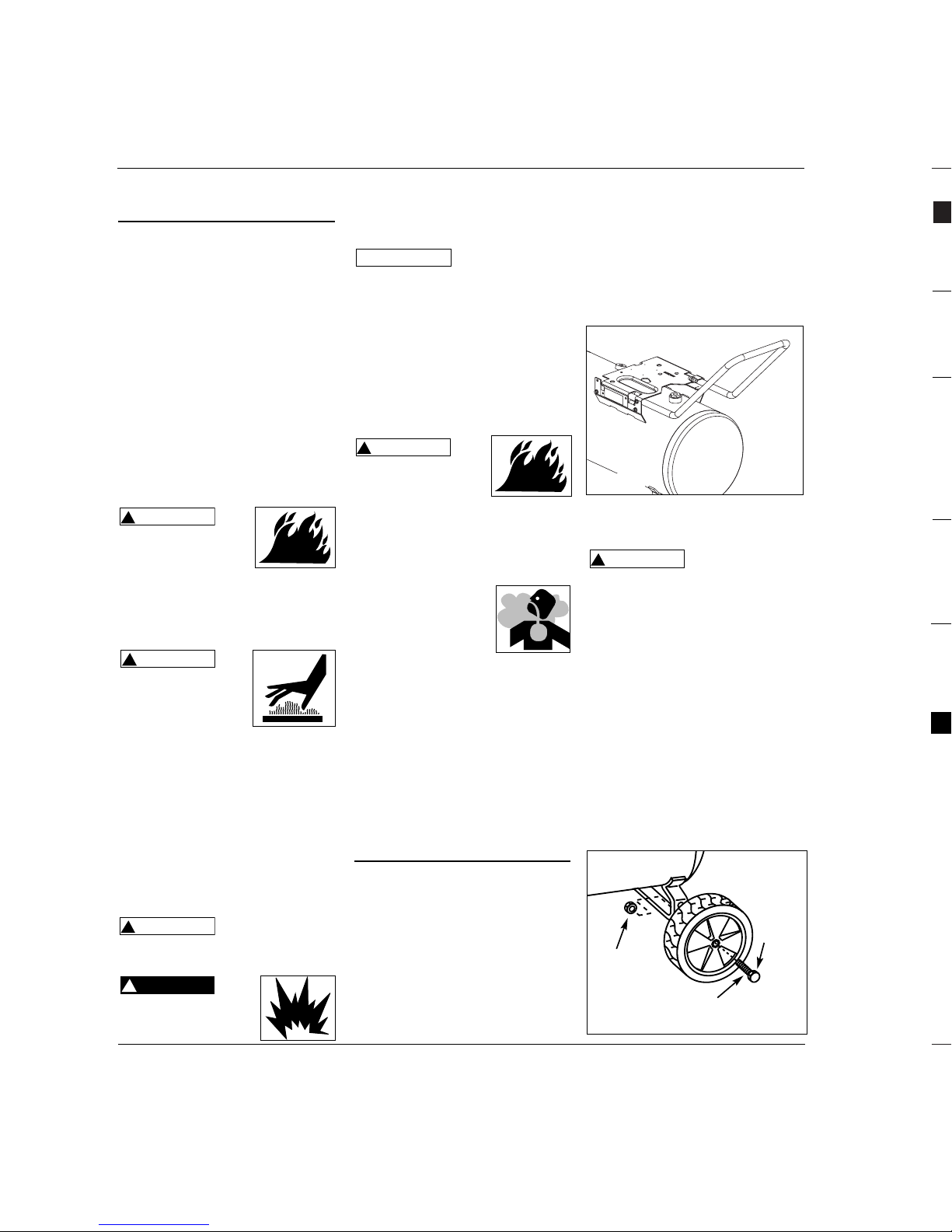
Assembly
HANDLE ASSEMBLY
Compressor handle has a notch (or
detent) at top of handle. This notch
provides a handy place to hang a spray
gun, sandblast gun, or other tool
equipped with a hook.
1. If a handle grip was included with
the unit, coat the inside of grip with
a thin film of soapy water. Push grip
onto handle.
!
WARNING
NOTICE
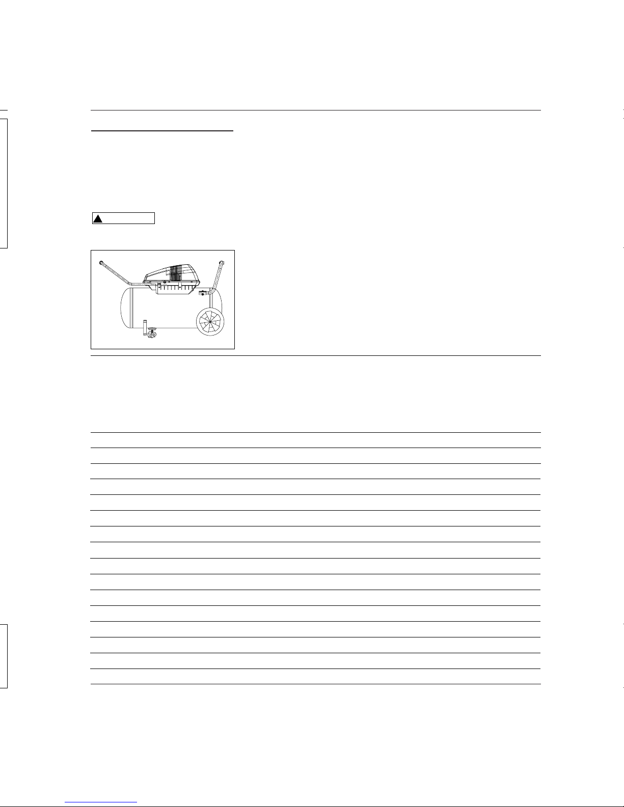
2. Insert handle through shroud and
into baseplate as shown in Figure 1.
Handle must fit into special openings
in baseplate.
3. Place a short piece of wood against
end of handle and tap it with a
mallet or hammer to drive handle
into baseplate until hole in handle
and baseplate line up.
4. Assemble and tighten 2 screws (from
parts package) through hole in baseplate ensuring it goes through handle.
Never use the
handle to lift the
unit completely off the ground. Only
use the handle to lift one end so the
wheels may be used to move the unit.
5. Insert threaded post of rubber foot
into hole in ground iron. Tighten
securely with locknut.
WHEEL ASSEMBLY
The items marked with an asterisk (*)
are included in parts package.
1. Insert shoulder bolt through wheel
hub. The bolt hex head should be
on the opposite side of protruding
hub center.
2. For 6 - 8 inch diameter wheels, feed
the shoulder bolt through the
bottom hole on the tank axle iron
and tightly secure with the locknut.
!
WARNING
Figure 1
Shoulder
bolt
*
*
Figure 2 - Wheel Assembly
Lock nut
Wheel
*
HERRAMIENTAS RECOMENDADAS
PARA USO CONTINUO
Llave de choque de mariposa
Criques
Pistolas rociadoras
Sierra neumática alternativa
Destornilladores
Martillos mecánicos para clavos pequeños
Martillos mecánicos para tirantería
Pistolas engrasadoras
Pistolas de calafatear
Limpiadores de motor
Page 3
WL6500 Series
3
Assembly (Con't)
For 10 inch diameter wheels, feed
the shoulder bolt through the top
hole on the tank axle iron and
tightly secure with the locknut.
Repeat on the opposite side.
OPTIONAL VERTICAL STORAGE
GROUND IRON
1. Push plastic plug into end of one inch
tube.
2. Assemble the grip onto the tube as
described in the handle assembly.
3. Assemble the tube to the tank as
shown in figure 8. Fasten the tube
with 5/16 inch locking bolts. Tighten
securely with 5/16 inch locking nuts.
4. Insert threaded post of rubber feet
into holes at top of tube. Tighten
securely with 5/16 inch locking nuts.
Installation
LOCATION
When assembled, the tank must sit
level or slope slightly towards the drain
cock to allow the tank to drain
properly.
It is extremely important to install the
compressor in a clean, well ventilated area
where the surrounding air temperature
will not be more than 100°F.
A minimum clearance of 18 inches
between the compressor and a wall is
required because objects could obstruct
air flow.
Do not locate the
compressor air
inlet near steam, paint spray, sandblast
areas or any other source of
contamination. This debris will damage
the motor.
ELECTRICAL INSTALLATION
All wiring and
electrical
connections should be performed by a
qualified electrician. Installation must be
in accordance with local codes and
national electrical codes.
Never use an extension
cord with this product. Use
additional air hose instead
of an extension cord to avoid power loss
and permanent motor damage. Use of an
extension cord voids the warranty.
!
CAUTION
!
WARNING
!
CAUTION
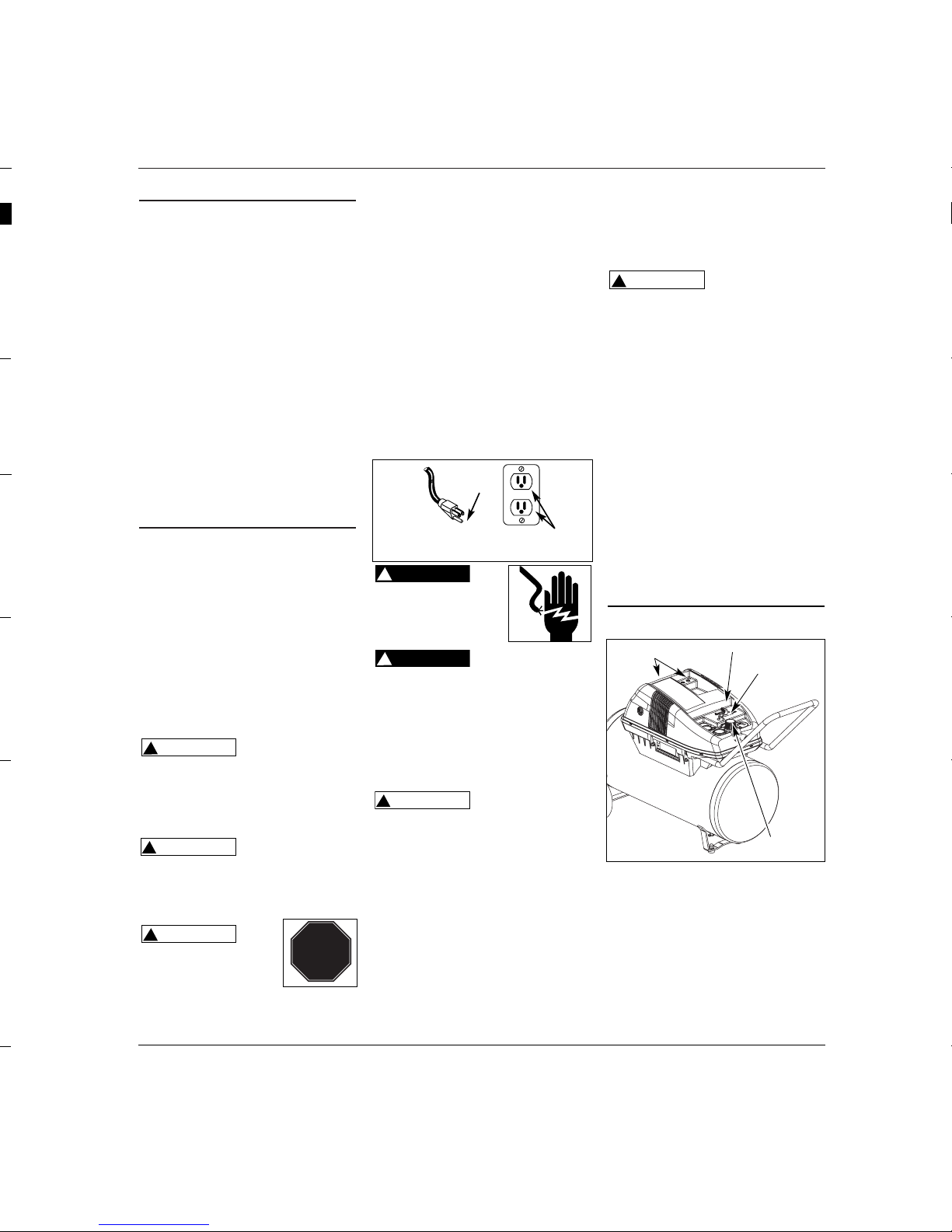
GROUNDING INSTRUCTIONS
1. This product is for use on a nominal
120 volt circuit and has a grounding
plug that looks like the plug illustrated
in Fig. 3. Make sure the product is
connected to an outlet having the
same configuration as the plug. This
product must be grounded. In the
event of an electrical short circuit,
grounding reduces risk of electrical
shock by providing an escape wire for
electric current. This product is
equipped with a cord having a
grounding wire with an appropriate
grounding plug. Plug must be plugged
into an outlet that is properly installed
and grounded in accordance with all
local codes and ordinances.
Improper use of
grounding plug can result in a possible risk of
electrical shock!
Do not use a
grounding adapter
with this product!
2. If repair or replacement of cord or plug
is necessary, do not connect grounding
wire to either flat blade terminal. The
wire with insulation having an external
surface that is green (with or without
yellow stripes) is the grounding wire.
Never connect
green (or green and
yellow) wire to a live terminal.
3. Check with a qualified electrician or
serviceman if grounding instructions
are not completely understood, or if in
doubt as to whether product is
properly grounded. Do not modify
plug provided; if it will not fit outlet,
have proper outlet installed by a
qualified electrician.
WIRING
1.
Local electrical wiring codes differ from
area to area. Source wiring, plug and
protector must be rated for at least the
!
WARNING
!
DANGER
!
DANGER
amperage and voltage indicated on
motor nameplate, and meet all electrical
codes for this minimum.
2. Use a slow blow fuse or a circuit
breaker.
Overheating, short
circuiting and fire
damage will result from inadequate
wiring, etc.
NOTE: 120 volt, 15 amp units can be
operated on a 120 volt circuit under the
following conditions:
a. No other electrical appliances or lights
are connected to the same branch
circuit.
b. Voltage supply is normal.
c. Circuit is equipped with a 15 amp
circuit breaker or a 15 amp slow blow
fuse.
3. If these conditions cannot be met or if
nuisance tripping of current
protection device occurs, it may be
necessary to operate compressor from
a 120 volt, 20 amp circuit.
Operation
Pressure Switch - Auto/Off Switch - In
the ON position, the compressor shuts
off automatically when tank pressure
reaches the maximum preset pressure.
The compressor will automatically
restart when it reaches the minimum
preset pressure. In the OFF position,
the compressor will not operate. This
switch should be in the OFF position
when connecting or disconnecting the
!
CAUTION
TEST
RESET
Figure 3 - Grounding Method
STOP!
Grounding
Pin
Grounded Outlet
Figure 4
Tool Storage
Pressure Switch
Safety Valve
Regulator
Page 4
Funcionamiento
(Continuacíon)
PERILLA DEL REGULADOR
1. Esta perilla controla el aire comprimido
que se le suministra a las herramientas
neumáticas o pistolas pulverizadoras.
2. Gire la perilla en el mismo sentido de
las agujas del reloj para aumentar la
presión de aire suminstrado.
3. Gire la perilla en sentido contrario al de
las agujas del reloj para disminuir la
presión de aire suministrado.
4. Gire la perilla completamente en
sentido contrario a las agujas del reloj
para cerrar el suministro de aire
completamente.
MANOMETRO PARA MEDIR LA
PRESION DE SALIDA
(HERRAMIENTA)
1. Este manómetro le
permite verificar la
presión de salida muy
fácilmente. Esta presión se
mide en barras.
2. Cerciórese de que el manómetro esté
en CERO antes de cambiar de
herramientas neumáticas o desconectar
la manguera.
MANOMETRO DEL TANQUE
Mide la presión del tanque
para verificar que el sistema
está funcionando
adecuadamente.
4
Operation (Continued)
power cord from the electrical outlet
or when changing air tools.
Regulator - The regulator controls the
amount of air pressure released at the
hose outlet.
ASME Safety Valve - This valve
automatically releases air if the tank
pressure exceeds the preset maximum.
Handle - Designed to move the
compressor.
Tool Storage - 1/4 inch quick connect
couplers fit in holes to support air
chuck and other inflation fittings.
Never use the
handle on wheeled
units to lift the unit completely off the
ground.
Drain Petcock - This valve is located on
the bottom of the tank. Use this valve
to drain moisture from the tank daily
to reduce the risk of corrosion.
Reduce tank pressure below 10 PSI,
then drain moisture from tank daily to
avoid tank corrosion. Drain moisture
from tank(s) by opening the drain
petcock located underneath the tank.
!
WARNING
LUBRICATION
This is an oilless product and DOES
NOT require lubrication to operate.
IMPORTANT: Do not operate compres-
sor before reading instructions or
damage may result.
1. Turn switch to OFF position and plug
in power cord.
2. Attach chuck or other tool to open
end of hose.
3. Turn regulator clockwise to open air
flow.
4. Turn switch to ON position.
5. Compressor will build to maximum
preset pressure and shut off.
6. Adjust regulator to proper pressure
for tool or tire. Operate tool per
instructions. Compressor will
automatically restart when pressure
in tank drops below cut-in pressure.
7. Turn regulator knob counterclockwise to shut off the air and turn
switch to Off position.
In the ON position, the compressor
pumps air into the tank. It shuts off
automatically when unit reaches its
maximum preset pressure. In the OFF
position, the compressor will not
operate. This switch should be in the
OFF position when connecting or
disconnecting the power cord from the
electrical outlet.
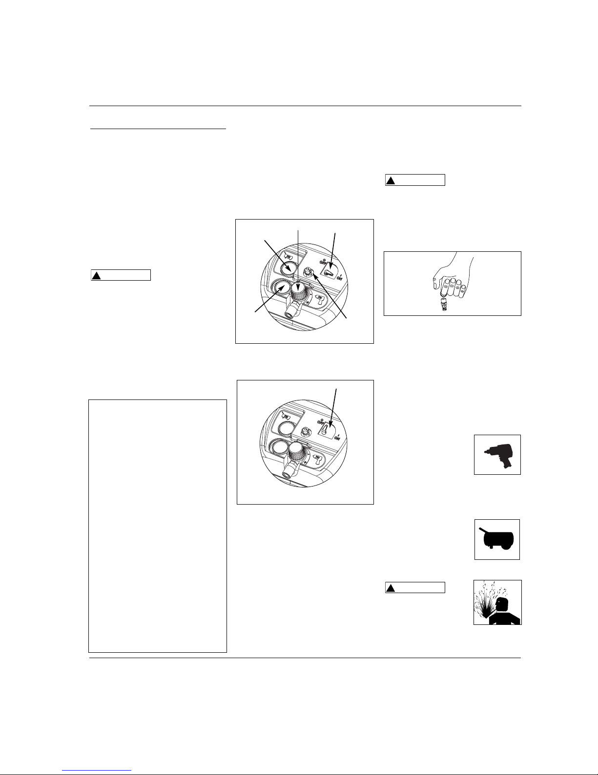
ASME SAFETY VALVE
Do not remove or
attempt to adjust
the safety valve!
This valve should be checked under
pressure occasionally by pulling the ring
by hand. If air leaks after ring has been
released, or valve is stuck and cannot be
actuated by ring, it MUST be replaced.
REGULATOR KNOB
1. This knob controls air pressure to an
air operated tool, or paint spray gun.
2. Turning knob clockwise increases air
pressure at outlet.
3. Turning counterclockwise will lower
air pressure at outlet.
4. Fully counterclockwise will shut off
flow of air completely.
OUTLET (TOOL) PRESSURE GAUGE
1. This gauge shows at-aglance, air pressure at
outlet. Air pressure is
measured in pounds
per square inch (psi).
2. Be sure this gauge reads ZERO before
changing air tools or disconnecting
hose from outlet.
TANK PRESSURE
GAUGE
Gauge shows pressure in
tank indicating
compressor is building
pressure properly.
Disconnect power source
then release all pressure
from the system before
attempting to install,
service, relocate or perform any
maintenance.
!
WARNING
!
WARNING
MOISTURE IN COMPRESSED AIR
Moisture in compressed air will
form into droplets as it comes from
an air compressor pump. When
humidity is high or when a
compressor is in continuous use for
an extended period of time, this
moisture will collect in the tank.
When using a paint spray or
sandblast gun, this water will be
carried from the tank through the
hose, and out of the gun as
droplets mixed with the spray
material.
IMPORTANT: This condensation
will cause water spots in a paint
job, especially when spraying other
than water based paints. If
sandblasting, it will cause the sand
to cake and clog the gun,
rendering it ineffective. A filter in
the air line (MP3105), located as
near to the gun as possible, will
help eliminate this moisture.
Oilless Compressors
PSI
PSI
Notas
Figure 7
Figure 5
Tank
Pressure
Regulator
On
Position
Safety
Valve
Tool
Pressure
Figure 6
Off
Position
Page 5
5
Maintenance
The compressor should be checked
often for any visible problems and the
following maintenance procedures
should be performed each time the
compressor is used.
1. Pull ring on safety valve and allow it
to snap back to normal position.
Safety valve must
be replaced if it
cannot be actuated or it leaks air after
ring is released.
!
WARNING
2. Place unit in the horizontal position
as shown in Figure 8. With
compressor shut off and pressure
released: Drain moisture from tank
by opening drain cock underneath
tank.
3. Turn power OFF and clean dust and
dirt from pump cover, tank and air
lines.
IMPORTANT: Unit should be located as
far from spraying area as hose will
allow to prevent over-spray from
clogging filter.
LUBRICATION
This is an oilless type compressor
requiring no lubrication.
STORAGE
1. When not in use, hose and compressor should be stored in a cool dry
place.
2. Tank should be drained of moisture.
3. Hose should be disconnected and
hung open ends down, to allow any
moisture to drain.
Figure 8
WL6500 Series
Notes
Page 6

Ensamblaje
(Continuacíon)
debe estar en el lado opuesto a la pieza
sobresaliente del centro del cubo.
2. En las ruedas de 15,24 cm (6”) - 20,32
cm (8”) de diámetro, introduzca el
perno en el orificio ubicado en la parte
inferior del eje de hierro del tanque y
asegúrelo bien con una tuerca de
seguridad. En las ruedas de 25,4 cm
(10”) de diámetro, introduzca el perno
en el orificio ubicado en la parte
superior del eje de hierro del tanque y
asegúrelo bien con una tuerca de
seguridad. Repita este paso en el otro
lado.
ELEMENTO METÁLICO OPCIONAL DE
CONEXIÓN A TIERRA PARA
POSICIÓN VERTICAL
1. Presione el tapón de plástico en el
extremo de tubo de una pulgada.
2. Monte el puño en el tubo como
indicado en el motaje del mango.
3. Monte el tubo en el tanque como se
indica en la figura 8. Ajuste el tubo
con pernos de seguridad de 5/16.
Ajuste firmemente con tuercas de
seguridad de 5/16.
4. Inserte el extremo roscado del pie de
caucho en los huecos al tope del
tubo. Ajuste firmemente con tuercas
de seguridad de 5/16.
Instalación
UBICACION
Una vez que lo ensamble, el tanque debe
estar nivelado o un poco inclinado hacia
el lado donde está la llave de drenaje de
modo que pueda drenarlo
adecuadamente.
Es de suma importancia instalar el
compresor en un llugar limpio y bien
ventilado donde la temperatura ambiente
no sea mayor de 38˚ C (100˚F).
Se requiere un espacio mínimo de 45,7 cm
(18 pulgadas) entre el compresor y la
*
*
Figura 2 - Para ensamblar las ruedas
Tuerca de
seguridad
6
Troubleshooting Chart
Symptom Possible Cause(s) Corrective Action
1. No electrical power
2. Breaker open
3. Pressure switch bad
4. Check valve defective
1. Poor contacts, line voltage incorrect
2. Shorted or open motor winding
3. Defective check valve or unloader
1. Incorrect size fuse, circuit overloaded
2. Defective check valve or unloader
1. Loose connections (fittings, tubing,
etc.)
2. Loose drain cock
3. Check valve leaking
1. Air leaks in piping (on machine or in
outside system)
2. Piston ring broken
1. Plugged in? Check fuse/breaker or motor overload
2. Reset, determine cause of problem
3. Replace
4. Remove and replace check valve
Do not disassemble check valve
with air in tank; bleed tank
1. Check connections, check with voltmeter
2. Replace motor
3. Replace or repair
Do not disassemble check valve
with air in tank; bleed tank
1. Check for proper fuse, use time-delay fuse.
Disconnect other electrical appliances from circuit or
operate compressor on its own branch circuit
2. Replace or repair
Do not disassemble check valve
with air in tank; bleed tank
1. Check all connections with soap and water solution
and tighten
2. Tighten
3. Disassemble check valve assembly, clean or replace
Do not disassemble check valve
with air in tank; bleed tank
1. Replace leaking components or tighten as necessary
2. Replace
!
DANGER
!
DANGER
!
DANGER
!
DANGER
Compressor will not run
Motor hums but cannot
run or runs slowly
Fuses blow/circuit
breaker trips repeatedly
Never use an extension
cord with this product
Tank pressure drops
when compressor shuts
off
Air output lower than
normal/low discharge
pressure
!
CAUTION
Oilless Compressors
Page 7

7
Troubleshooting Chart (Continued)
Symptom Possible Cause(s) Corrective Action
1. Excessive water in tank
2. High humidity
1. Defective pressure switch
2. Excessive air usage
1. Excessive condensation in tank
2. Air leaks in piping (on machine or in
outside system)
3. Tank check valve leaking
Check valve stuck in an open position
Belt broken
1. Drain tank
2. Move to area of less humidity; use air line filter
1. Replace switch
2. Decrease air usage; compressor not large enough for
air requirement
1. Drain more often
2. Replace leaking components or tighten as necessary
3. Replace or repair as necessary
Do not disassemble check valve
with air in tank; bleed tank
Remove and replace check valve
Do not disassemble check valve
with air in tank; bleed tank
Replace belt
!
DANGER
!
DANGER
Excessive moisture in
discharge air
Compressor runs
continuously
Excessive starting and
stopping (auto start)
Air leaking from
unloader on pressure
switch
Motor runs but no air
output
WL6500 Series
Tool Recommendations for this Air Compressor
RECOMMENDED TOOLS FOR
CONTINUOUS USE
Butterfly impact wrench
Ratchets
Spray guns
Reciprocating saws
Screwdrivers
Brad nailers
Framing nailers
Grease guns
Caulk guns
Engine cleaners
RECOMMENDED TOOLS FOR
INTERMITTENT USE
(Short powerful bursts)
Impact wrenches
Die grinders
Drills
Chisels
Cut-off tools
TOOLS NOT RECOMMENDED
Straight line sanders
Highspeed sanders
Dual action sanders
Jitterbug sanders
Page 8

Sírvase leer y guardar estas instrucciones.Lea con cuidado antes de tratar de armar, instalar, manejar o darle servicio al producto descrito en
este manual. Protéjase Ud. y a los demás observando todas las reglas de seguridad. El no seguir las instrucciones podría resultar en heridas y/o
daños a su propiedad. Guarde este manual como referencia.
Descripción
Los compresores sin aceite han sido
diseñados para una gran variedad de
trabajos domésticos y mecánica
automotriz. Estos compresores se utilizan
con pistolas rociadoras, llaves de impacto
y otras herramientas neumáticas. Estas
unidades funcionan sin aceite.
Medidas de Seguridad
Este manual contiene información que es
muy importante que sepa y comprenda.
Esta información se la suministramos
como medida de SEGURIDAD y para
EVITAR PROBLEMAS CON EL EQUIPO.
Debe reconocer los siguientes símbolos.
hay una situación inmediata que LE
OCASIONARIA la muerte o heridas de
gravedad.
hay una situación que PODRIA ocasionarle
la muerte o heridas de gravedad.
hay una situación que PODRIA ocasionarle
heridas no muy graves.
información importante, que de no
seguirla, le podría ocasionar daños al
equipo.
Para Desempacar
Cuando desempaque la unidad,
inspecciónela cuidadosamente para
verificar si se han producido daños
durante el transporte. Asegúrese de
apretar todos los accesorios, pernos, etc.
AVISO
!
PRECAUCION
!
ADVERTENCIA
!
PELIGRO
Instrucciones para la Operacion Serie WL6500
8
WL6500 Series
Oilless Compressors
Limited Warranty - Husky Air Compressors by Campbell Hausfeld
1. DURATION: From the date of purchase by the original purchaser as follows: One Year.
2. WHO GIVES THIS WARRANTY (WARRANTOR):
Campbell Hausfeld / Scott Fetzer Company, 100 Production Drive, Harrison, Ohio, 45030, Telephone: (800) 543-6400
3. WHO RECEIVES THIS WARRANTY (PURCHASER): The original purchaser (other than for purposes of resale) of the Campbell
Hausfeld compressor.
4. WHAT PRODUCTS ARE COVERED BY THIS WARRANTY: Any Campbell Hausfeld air compressor.
5. WHAT IS COVERED UNDER THIS WARRANTY: Substantial defects due to material and workmanship with the exceptions noted
below.
6. WHAT IS NOT COVERED UNDER THIS WARRANTY:
A. Implied warranties, including those of merchantability and FITNESS FOR A PARTICULAR PURPOSE ARE LIMITED FROM THE
DATE OF ORIGINAL PURCHASE AS STATED IN THE DURATION. If this compressor is used for commercial, industrial or rental
purposes, the warranty will apply for ninety (90) days from the date of purchase. Four cylinder single-stage and two-stage
compressors are not limited to a ninety (90) day warranty when used in commercial or industrial applications. Some States
do not allow limitations on how long an implied warranty lasts, so the above limitations may not apply to you.
B. ANY INCIDENTAL, INDIRECT, OR CONSEQUENTIAL LOSS, DAMAGE, OR EXPENSE THAT MAY RESULT FROM ANY DEFECT,
FAILURE, OR MALFUNCTION OF THE CAMPBELL HAUSFELD PRODUCT. Some States do not allow the exclusion or limitations
of incidental or consequential damages, so the above limitation or exclusion may not apply to you.
C. Any failure that results from an accident, purchaser’s abuse, neglect or failure to operate products in accordance with
instructions provided in the owner’s manual(s) supplied with compressor.
D. Pre-delivery service, i.e. assembly, oil or lubricants, and adjustment.
E. Items or service that are normally required to maintain the product, i.e. lubricants, filters and gaskets, etc.
F. Gasoline engines and components are expressly excluded from coverage under this limited warranty. The Purchaser must
comply with the warranty given by the engine manufacturer which is supplied with the product.
G. Additional items not covered under this warranty:
1. All Compressors
a. Any component damaged in shipment or any failure caused by installing or operating unit under conditions not in
accordance with installation and operation guidelines or damaged by contact with tools or surroundings.
b. Pump or valve failure caused by rain, excessive humidity, corrosive environments or other contaminants.
c. Cosmetic defects that do not interfere with compressor functionality.
d. Rusted tanks, including but not limited to rust due to improper drainage or corrosive environments.
e. Electric motors, check valves and pressure switches after the first year of ownership.
f. Drain cocks.
g. Damage due to incorrect voltage or improper wiring.
h. Other items not listed but considered general wear parts.
i. Pressure switches, air governors and safety valves modified from factory settings.
2. Lubricated Compressors
a. Pump wear or valve damage caused by using oil not specified.
b. Pump wear or valve damage caused by any oil contamination or by failure to follow proper oil maintenance
guidelines.
3. Belt Drive / Direct Drive / Gas Driven Compressors
a. Belts.
b. Ring wear or valve damage from inadequate filter maintenance.
c. Manually adjusted load/unload and throttle control devices.
7. RESPONSIBILITIES OF WARRANTOR UNDER THIS WARRANTY: Repair or replace, at Warrantor’s option, compressor or
component which is defective, has malfunctioned and/or failed to conform within duration of the warranty period.
8. RESPONSIBILITIES OF PURCHASER UNDER THIS WARRANTY:
A. Provide dated proof of purchase and maintenance records.
B. Portable compressors or components must be delivered or shipped to the nearest Campbell Hausfeld Authorized Service
Center. Freight costs, if any, must be borne by the purchaser.
C. Use reasonable care in the operation and maintenance of the products as described in the owner’s manual(s).
9. WHEN WARRANTOR WILL PERFORM REPAIR OR REPLACEMENT UNDER THIS WARRANTY: Repair or replacement will be
scheduled and serviced according to the normal work flow at the servicing location, and depending on the availability of
replacement parts.
Limited Warranty applies in the U.S. and Canada only and gives you specific legal rights. You may also have other rights which
vary from State to State or country to country.
Page 9

1. Lire attentivement tous
manuels compris avec ce
produit. Se familiariser
avec ce produit, ses
commandes et son utilisation.
2. Suivre tous les codes de sécurité
locaux ainsi que les National Electrical
Codes (NEC) and Occupational Safety
and Health Act (OSHA) des É-U.
Ne pas
utiliser un
modèle qui a été endommagé pendant le
transport, la manipulation ou l’utilisation.
Le dommage peut résulter en explosion et
peut causer des blessures ou dégâts
matériels.
Généralités Sur La
Sécurité
Puisque le compresseur d’air et les autres
pièces détachées (pompe, pistolets, filtres,
graisseurs, tuyaux, etc.) font partie d’un
système de haute pression, il est
nécessaire de suivre les précautions
suivantes:
!
AVERTISSEMENT
S’il vous plaît lire et conserver ces instructions. Lire attentivement avant de monter, installer, utiliser ou de procéder à l’entretien du produit
décrit. Se protéger ainsi que les autres en observant toutes les instructions de sécurité, sinon, il y a risque de blessure et/ou dégâts matériels!
Conserver ces instructions comme référence.
9Fr
Description
Les compresseurs sans huile sont conçus
pour les bricoleurs avec projets
domestiques et d’automobile. Ces
compresseurs servent à faire fonctionner
les pistolets à peinture, clés à chocs et
autres outils. Ces modèles
fonctionnent sans huile.
Directives de Sécurité
Ce manuel contient de l’information très
importante qui est fournie pour la
SÉCURITÉ et pour ÉVITER LES PROBLÈMES
D’ÉQUIPEMENT. Rechercher les symboles
suivants pour cette information.
Danger
indique
une situation hasardeuse imminente qui
RÉSULTERA en perte de vie ou blessures
graves.
Avertis-
sement
indique une situation hasardeuse
potentielle qui PEUT résulter en perte de
vie ou blessures graves.
Attention
indique
une situation hasardeuse potentielle qui
PEUT résulter en blessures.
Avis
indique
de l’information importante pour éviter le
dommage de l’équipement.
Déballage
Lors du déballage de ce produit,
l’examiner soigneusement pour
rechercher toute trace de dommage
susceptible de s’être produit en cours de
transport. Veiller à serrer tous raccords,
boulons, etc., avant de mettre ce produit
en service. En cas de dommage ou de
pièces manquantes, S.V.P. composer le
1-800-543-8622 pour demander conseil.
AVIS
!
ATTENTION
!
AVERTISSEMENT
!
DANGER
Instructions d’Utilisation Série WL6500
IN605200AV 3/02
Avertissement d’Air Respirable
Ce compresseur/pompe n’est pas
équipé pour et ne devrait pas être
utilisé “comme soi” pour fournir de l’air
respirable. Pour les applications d’air
pour la consommation humaine, il est
nécessaire d’équiper le compresseur
d’air/pompe avec de l’équipement de
sécurité en canalisation et d’alarme. Cet
équipement additionnel est nécessaire
pour filtrer et purifier l’air afin
d’atteindre les spécifications minimales
pour la respiration Grade D décrite
dans le Compressed Gas Association
Commodity Specification G 7.1 - 1966,
OSHA 29 CFR 1910. 134, and/or
Canadian Standards Associations
(CSA).
DÉNÉGATION DES GARANTIES
Si le compresseur est utilisé pour les
applications d’air respirable et
l’équipement de sécurité en
canalisation et d’alarme n’est pas utilisé
simultanément, les garanties en
existance seront annulées, et Campbell
Hausfeld dénie toute responsabilité
pour n’importe quelle perte, blessure
ou dommage.
!
DANGER
ARRÊT!
Enregistrer le No. de Modèle, No. de
Série, et la Date d’Achat située sur la base
de la pompe dans l’espace ci-dessous.
No. de Modèle ____________________
No. de Série ____________________
Date d’Achat ____________________
Garder ces numéros pour référence
Compresseurs
d’Air Sans Huile
MANUEL
NE PAS RENVOYER LE
PRODUIT AU
MARCHAND!
Page 10

Guide de Dépannage (Suite)
Symptôme Cause(s) Possible(s) Mesures Correctives
Humidité excessive dans
l’air de débit
Le compresseur
fonctionne
continuellement
Démarrage et coupage
excessif (démarrage
automatique)
Fuite d’air de l’appareil
de déchargement sur le
manostat
Le moteur fonctionne,
mais il n’y a pas de
débit d’air
10 Fr
Compresseurs Sans Huile
Généralités Sur La
Sécurité (Suite)
3. Seules les personnes bien familiarisées
avec ces règles d’utilisation doivent
être autorisées à se servir du
compresseur.
4. Garder les visiteurs à l’écart de/et NE
JAMAIS permettre les enfants dans
l’endroit de travail.
5. Utiliser des lunettes de sécurité et la
protection auditive pendant
l’utilisation du modèle.
6. Ne pas se tenir debout sur/ni utiliser le
modèle comme une prise à main.
7. Inspecter le système d’air comprimé et
pièces détachées électriques pour
toute indication de dommage,
détérioration, faiblesse ou fuites
avant chaque utilisation. Réparer ou
remplacer toutes pièces défectueuses
avant l’utilisation.
8. Inspecter le degré de serrage de
toutes attaches par intervalles
régulières.
Les moteurs, l’équipement et
les commandes électriques
peuvent produire des arcs
électriques qui peuvent allumer les gaz ou
vapeurs inflammables. Ne jamais faire
fonctionner ni réparer près des gaz ou
vapeurs inflammables. Ne jamais ranger
ni pulvériser des liquides ou gaz
inflammables près du compresseur.
Les pièces du compresseur
peuvent être chaudes, même si
le modèle est hors circuit.
9. Garder les doigts à l’écart du
compresseur; les pièces mobiles et
chaudes peuvent causer des blessures
et/ou des brûlures.
10. Si l’équipement vibre anormalement,
ARRÊTER le moteur et l’inspecter
immédiatement. La vibration est
généralement une indication d’un
problème.
11. Pour réduire le risque d’incendie,
garder l’extérieur du moteur libre
d’huile, de solvant ou de graisse
excessive.
Ne jamais
enlever
ou essayer d’ajuster la soupape de sûreté.
!
AVERTISSEMENT
!
ATTENTION
!
AVERTISSEMENT
Garder la soupape de sûreté libre de
peinture et d’autres accumulations.
Ne jamais essayer de réparer
ou de modifier un réservoir! Le
soudage, perçage ou autre modifications
peuvent affaiblir le réservoir et peuvent
résulter en dommage de rupture ou
d’explosion. Toujours remplacer un
réservoir usé, fendu ou endommagé.
Purger le
réservoir
quotidiennement.
13. L’accumulation d’humidité cause la
rouille qui peut affaiblir le réservoir.
Purger le réservoir quotidiennement
et l’inspecter périodiquement pour la
rouille et la corrosion ou autre
dommage.
14. L’air mouvante peut agiter la
poussière et le débris qui peut être
dangereux. Lâcher l’air lentement en
purgeant l’humidité ou pendant la
dépressurisation du système du
compresseur.
PRÉCAUTIONS DE PULVÉRISATION
Ne pas pulvériser les matériaux
inflammables dans un endroit
de flamme ouverte ni près
d’une source d’ignition y compris le
compresseur.
15. Ne pas fumer pendant la
pulvérisation de la peinture,
d’insecticides ou autres matières
inflammables.
16. Utiliser un masque/
respirateur pendant la
pulvérisation et pulvériser
dans un endroit bien
ventilé pour éviter le risque de
blessures et d’incendie.
17. Ne pas diriger la peinture ou autre
matériel pulvérisé vers le
compresseur. Situer le compresseur
aussi loin que possible de l’endroit de
pulvérisation pour réduire
l’accumulation de surpulvérisation sur
le compresseur.
18. Suivre les instructions du fabricant
pendant la pulvérisation ou le
nettoyage avec des solvants ou
produits chimiques toxiques.
!
AVERTISSEMENT
AVIS
!
DANGER
Assemblage
MONTAGE DU MANCHE
L’encoche sur le haut du manche du
compresseur fournit un endroit
convenable pour accrocher un pistolet
vaporisateur, pistolet pour le décapage
au sable ou autre outil équipé d’un
crochet.
1. Si une poignée est comprise avec le
modèle, couvrir l’intérieure de la
poignée avec une couche mince
d’eau savonneuse. Pousser la
poignée sur le manche.
2. Introduire le manche à travers le
couvercle de protection et dans la
plaque de base tel qu’indiqué sur la
Figure 1. Le manche doit s’ajuster
dans les ouvertures spéciaux dans la
plaque de base.
3. Placer un morceau de bois court contre
le bout du manche et le frapper avec
un maillet ou un marteau pour
enfoncer la poignée dans la plaque de
base jusqu’à ce que les trous du
manche et la plaque de base soient
alignés.
4. Monter et serrer 2 vis (du paquet de
pièces) à travers le trou dans la plaque
de base et à travers le manche.
Ne
jamais
utiliser le manche pour complètement
soulever l’appareil. Utiliser le manche
pour soulever un bout et utiliser les roues
pour déplacer le modèle.
5. Introduire la pièce de montage du
pied en caoutchouc dans le trou du
fer de mise à la terre. Bien le serrer
avec l’écrou de serrage.
MONTAGE DE ROUES
Les articles indiqués d’un astérisque (*)
sont inclus dans le paquet de pièces.
1. Introduire le boulon à épaulement à
travers le moyeu de la roue. La tête
hexagonale du boulon devrait être au
sens opposé du centre proéminent du
moyeu.
!
AVERTISSEMENT
Figure 1
OUTILS RECOMMANDÉS POUR UNE
UTILISATION CONTINUE
Clés à choc papillon
Clés à cliquet
Pistolets de pulvérisation
Scies alternatives
Tournevis
Pistolets à pointe
Cloueurs de charpente
Pistolets à graisse
Pistolets à calfeutrer
Nettoyeurs à moteur
Page 11

Assemblage (Suite)
2. Pour les roues de diamètre de 15,24
cm - 20,32 cm, passer le boulon à
épaulement à travers le trou inférieur
de l’axe du réservoir et bien le serrer
avec l’écrou de serrage. Pour les roues
de diamètre de 25,40 cm, passer le
boulon à épaulement à travers le trou
supérieur sur l’axe du réservoir et bien
le serrer avec l’écrou de serrage.
Répéter au sens opposé.
RANGEMENT VERTICAL OPTIONNEL
FER DE MISE À LA TERRE
1. Pousser le bouchon de plastique à
l’extrémité d’un tube de 2,54 cm.
2. Assembler la poignée dans le tube tel
que décrit sous l’assemblage du
manche.
3. Assembler le tube au réservoir tel
qu’indiqué sous la figure 8. Fixer le
tube avec des boulons de serrage de
7,94 mm. Resserrer bien avec les
écrous de serrage de 7,94 mm.
4. Insérer la pièce fileté du pied de
caoutchouc dans les trous sur le
dessus du tube. Bien resserrer avec
les écrous de serrage de 7,94 mm.
Installation
ENDROIT
Une fois monté, le réservoir doit être
nivelé ou incliné un peu vers le robinet de
vidange afin de permettre le vidange
correct.
Il est très important d’installer le
compresseur dans un endroit propre et
bien ventilé où la température n’excédera
pas 38ºC (100ºF).
Un espace libre minimum de 45,7
centimètres entre le compresseur et un
mur est exigé pour éviter le stoppage d’air
par des objets.
Série WL6500
11 Fr
Ne pas
situer la
prise d’air du compresseur près de la
vapeur, un jet pulvérisé de peinture,
endroits de décapage au sable ou autre
sources de contamination. Le débris
endommagera le moteur.
INSTALLATION ÉLECTRIQUE
Seul un
électricien
qualifié doit effectuer l’installation
électrique et raccordements électriques.
Respecter toutes les codes locals et
nationales de l’électricité.
Ne jamais utiliser un cordon
prolongateur avec ce produit.
Utiliser un tuyau flexible à air additionnel
au lieu d’un cordon prolongateur pour
éviter une perte de puissance et dommage
du moteur. Usage d’un cordon
prolongateur sert à annuler la garantie.
INSTRUCTIONS DE MISE À LA TERRE
1. Ce produit est conçu pour l’utilisation
d’un circuit de 120 volts et a une fiche
de mise à la terre comme celle indiquée
sur la Fig. 3. S’assurer que le modèle soit
branché à une prise de courant qui a la
même configuration que la fiche. Ce
produit doit être mis à la terre. Dans
l’évenement d’un court-circuit, la mise à
la terre diminue le risque de secousse
électrique en fournissant un fil
d’échappement pour le courant
électrique. Ce produit est équipé d’un
cordon qui a un fil de terre avec une
fiiche de terre. La fiche doit être
branchée dans une prise de courant qui
a été installée et mise à la terre
correctement en respectant tous les
codes et règlements locaux.
L’usage incorrect d’une fiche de
mise à la terre peut résulter
en secousse électrique!
Ne pas
utiliser un
!
DANGER
!
DANGER
!
ATTENTION
!
AVERTISSEMENT
!
ATTENTION
adaptateur de mise à la terre avec ce
produit!
2. Si la réparation ou le remplacement du
cordon ou de la fiche est nécessaire, ne
pas connecter le fil de terre à ni une ni
l’autre borne plate. Le fil avec l’isolation
qui a une surface externe verte (avec ou
sans jaunes) est le fil de terre.
Ne jamais
brancher
le fil vert (ou vert et jaune) à une borne
électrisée.
3. Si vous ne comprenez pas les
instructions pour la mise à la terre ou si
vous n’êtes pas certains si le produit est
mis à la terre correctement, vérifier
avec un électricien ou une personne
qualifiée. Ne pas modifier la fiche
fournie; si la fiche n’est pas la bonne
taille pour la prise de courant, contacter
un électricien qualifié pour l’installation
d’une nouvelle prise de courant.
INSTALLATION DE FILS
1. Les codes électriques d’installation de
fils sont variables d’un endroit à
l’autre. Les fils d’alimentation, fiche et
protecteurs doivent être classifiés pour
au moins l’ampérage et la tension
indiqués sur la plaque indicatrice du
moteur et doivent répondre aux codes
électriques pour ce minimum.
2. Utiliser une fusée à retardement ou un
disjoncteur.
L’instal-
lation de
fils insuffisante peut résulter en
surchauffage, court-circuit et en
dommage d’incendie.
REMARQUE: Les modèles de 120 V, 15A
peuvent fonctionner sur un circuit de 120
V sous les conditions suivantes:
a. Aucun autre appareil électrique ou
lumière est connecté au même
branchement.
b. L’alimentation en tension est
normale.
c. Le circuit est équipé avec un
disjoncteur de 15 ampères ou une
fusée à retardement de 15 ampères.
3. S’il n’est pas possible d’atteindre les
conditions ci-dessus ou s’il y a un
déclenchement du protecteur de
courant à maintes reprises, il peut être
nécessaire de faire fonctionner le
compresseur sur un circuit de 120 volts,
20 ampères.
!
ATTENTION
!
AVERTISSEMENT
TEST
RESET
Figure 3 - Méthode de mise à la terre
ARRÊT!
Broche
de Terre
Boulon à
épaulement
*
*
Figure 2 - Montage De Roues
Écrou de
serrage
Roue
Prise de Courant Mise de Terre
*
Page 12

sens des aiguilles d’une montre pour
ouvrir la circulation d’air.
4. Tourner l’interrupteur à la position ON.
5. Le compresseur accumulera la pression
jusqu’à ce qu’il atteint la pression
réglée d’avance et s’arrêtera.
6. Ajuster le régulateur à la bonne
pression (outil ou pneu). Utiliser
l’outil conformément aux
instructions. Le compresseur se
remettra automatiquement en
marche lorsque la pression du
réservoir tombe sous la pression
d’enclenchement.
7. Tourner le bouton du régulateur au
sens inverse des aiguilles d’une montre
afin de couper l’air et ensuite tourner
l’interrupteur à la position Off.
Dans la position ON, le compresseur
pompe de l’air dans le réservoir. Il se
coupe automatiquement quand il atteint
la pression maximale réglée d’avance. Le
compresseur ne fonctionnera pas dans
la position OFF. Cet interrupteur devrait
être dans la position OFF pendant le
branchement et le débranchement du
cordon d’alimentation d’une prise de
courant.
SOUPAPE DE SÛRETÉ ASME
Ne jamais
enlever
ou essayer d’ajuster la soupape de sûreté!
Vérifier cette soupape lorsque sous
pression de temps à temps en tirant
l’anneau à la main. La soupape DOIT être
remplacée s’il y a des fuites d’air une fois
que l’anneau soit relâché ou si la soupape
est grippée et ne fonctionne pas avec
l’anneau.
!
AVERTISSEMENT
Fonctionnement
(Suite)
BOUTON DU RÉGULATEUR
1. Ce bouton règle la pression à un outil
pneumatique ou à un pistolet
vaporisateur.
2. La pression d’air à la sortie est
augmentée en tournant le bouton au
sens des aiguilles d’une montre.
3. La pression d’air à la sortie est réduite
en tournant le bouton au sens inverse
des aiguilles d’une montre.
4. Pour couper le débit d’air, tourner
complètement au sens inverse des
aiguilles d’une montre.
MANOMÈTRE DE SORTIE (OUTIL)
1. Ce manomètre indique la
pression d’air de sortie.
La pression d’air est
mesurée en kPa.
2. S’assurer que le manomètre est à ZERO
avant de changer les outils
12 Fr
Fonctionnement
Manostat - Interrupteur Auto/Off. Dans
la position ON, le compresseur se coupe
automatiquement quand la pression du
réservoir arrive à la pression maximale
réglée d’avance. Le compresseur se
mettra en marche automatiquement
une fois qu’il atteigne la pression
minimum réglée d’avance. Dans la
position OFF, le compresseur ne
fonctionnera pas. Cet interrupteur
devrait être dans la position OFF pendant
le branchement ou le débranchement du
cordon d’alimentation de la prise de
courant ou pendant le changement
d’outils pneumatiques.
Régulateur - Le régulateur sert à régler
la pression d’air à la sortie du tuyau.
Soupape de Sûreté ASME - Cette
soupape laisse échapper l’air si la pression
du réservoir dépasse la pression
maximum réglée d’avance.
Manche - Conçue pour le déplacement
du compresseur.
Rangement d’Outils - les raccords
rapides d’1/4 po s’ajustent dans les
trous afin de supporter un mandrin et
autres raccords de gonflage.
Ne jamais
utiliser le
manche sur les modèles avec roues pour
soulever le modèle.
Robinet de Purge - Cette soupape est
située sur la base du réservoir. Utiliser
cette soupape pour purger l’humidité du
réservoir quotidiennement afin de
réduire le risque de corrosion.
Baisser la pression du réservoir sous 69
kPa, et ensuite purger l’humidité du
réservoir afin d’éviter la corrosion. Purger
l’humidité du/des réservoir(s) en ouvrant
le robinet de purge situé sur la base du
réservoir.
LUBRIFICATION
Ce produit est “sans-huile” et n’exige
pas d’huile pour fonctionner.
IMPORTANT: Pour éviter du dommage
au compresseur, lire toutes les
instructions avant de l’utiliser.
1. Tourner l’interrupteur à la position OFF
et brancher le cordon d’alimentation.
2. Fixer un mandrin ou autre outil au bout
ouvert du tuyau.
3. Faire tourner le régulateur dans le
!
AVERTISSEMENT
L’HUMIDITÉ DANS L’AIR COMPRIMÉ
L’humidité dans l’air comprimé
forme des goutelettes en arrivant de
la pompe du compresseur. Si
l’humidité est élevée ou si le
compresseur est utilisé
continuellement, cette humidité
s’accumulera dans le réservoir. En
utilisant un pistolet à peinture ou un
pistolet pour décapage au sable,
cette eau sera transportée hors du
réservoir par moyen du tuyau en
forme de goutelettes mélangées
avec le matériel utilisé.
IMPORTANT: Cette condensation
peut avoir comme résultat des
taches d’eau sur votre travail de
peinture, surtout en pulvérisant la
peinture qui n’est pas de base d’eau.
Pendant la décapage au sable,
(MP3105) cette eau servira à tenir le
sable ensemble et à causer une
obstruction dans le pistolet.
Compresseurs Sans Huile
Notes
Figure 5
Pression de
Réservoir
Régulateur
Soupape
de
Sûreté
Pression
de
l’Outil
Position
de Marche
(on)
Figure 6
Position
hors
circuit
(off)
Figure 4
Endroit de Rangement
d’Outils
Manostat
Soupape de
sûreté
Régulateur
Figure 7
Page 13

13 Fr
Fonctionnement
(Suite)
BOUTON DU RÉGULATEUR
1. Ce bouton règle la pression à un outil
pneumatique ou à un pistolet
vaporisateur.
2. La pression d’air à la sortie est
augmentée en tournant le bouton au
sens des aiguilles d’une montre.
3. La pression d’air à la sortie est réduite
en tournant le bouton au sens inverse
des aiguilles d’une montre.
4. Pour couper le débit d’air, tourner
complètement au sens inverse des
aiguilles d’une montre.
MANOMÈTRE DE SORTIE (OUTIL)
1. Ce manomètre indique la
pression d’air de sortie.
La pression d’air est
mesurée en kPa.
2. S’assurer que le manomètre est à ZERO
avant de changer les outils
pneumatiques ou avant de débrancher
le tuyau de la sortie.
MANOMÈTRE DU RÉSERVOIR
Le manomètre indique la
pression dans le réservoir ce
qui indique que le
compresseur fonctionne
bien.
Entretien
Débrancher de la source de
puissance et ensuite dissiper
toute la pression du système
avant d’essayer d’installer, de réparer, de
déplacer ou de procéder à l’entretien.
Inspecter le compresseur souvant et
suivre les procédés d’entretien suivants
pendant chaque utilisation du
compresseur.
1. Tirer sur l’anneau de la soupape de
sûreté et la laisser revenir à sa position
normale.
S’il y a
une fuite
après que la soupape soit lâchée ou si la
soupape ne fonctionne pas, elle devrait
être remplacée.
2. Placer l’appareil en position
horizontale tel qu’indiqué sous la
Figure 8. Avec le compresseur hors
circuit et la pression dissipée, purger
!
AVERTISSEMENT
!
AVERTISSEMENT
l’humidité du réservoir en ouvrant le
robinet de purge sous le réservoir.
3. Mettre hors circuit (OFF) et nettoyer
la poussière et la saleté du couvercle
de la pompe, du réservoir et des
canalisations d’air.
IMPORTANT: Situer le modèle aussi loin
de l’endroit de pulvérisation que possible
afin d’empêcher que le filtre deviennent
obstrué par la surpulvérisation.
GRAISSAGE
Ce modèle “sans huile” n’exige pas de
graissage.
ENTREPOSAGE
1. Entreposer les tuyaux et le compresseur dans un endroit frais et sec.
2. Le réservoir doit être purgé d’humidité.
3. Le tuyau doit être débranché et
suspendu avec les bouts ouverts face
en bas pour laisser couler l’humidité.
Série WL6500
PSI
PSI
Notes
kPa
kPa
Figure 7
Figure 8
Page 14

Assemblage (Suite)
2. Pour les roues de diamètre de 15,24
cm - 20,32 cm, passer le boulon à
épaulement à travers le trou inférieur
de l’axe du réservoir et bien le serrer
avec l’écrou de serrage. Pour les roues
de diamètre de 25,40 cm, passer le
boulon à épaulement à travers le trou
supérieur sur l’axe du réservoir et bien
le serrer avec l’écrou de serrage.
Répéter au sens opposé.
RANGEMENT VERTICAL OPTIONNEL
FER DE MISE À LA TERRE
1. Pousser le bouchon de plastique à
l’extrémité d’un tube de 2,54 cm.
2. Assembler la poignée dans le tube tel
que décrit sous l’assemblage du
manche.
3. Assembler le tube au réservoir tel
qu’indiqué sous la figure 8. Fixer le
tube avec des boulons de serrage de
7,94 mm. Resserrer bien avec les
écrous de serrage de 7,94 mm.
4. Insérer la pièce fileté du pied de
caoutchouc dans les trous sur le
dessus du tube. Bien resserrer avec
les écrous de serrage de 7,94 mm.
Installation
ENDROIT
Une fois monté, le réservoir doit être
nivelé ou incliné un peu vers le robinet de
vidange afin de permettre le vidange
correct.
Il est très important d’installer le
compresseur dans un endroit propre et
bien ventilé où la température n’excédera
pas 38ºC (100ºF).
Un espace libre minimum de 45,7
centimètres entre le compresseur et un
mur est exigé pour éviter le stoppage d’air
par des objets.
*
*
Figure 2 - Montage De Roues
Écrou de
serrage
14 Fr
Guide de Dépannage
Symptôme Cause(s) Possible(s) Mesures Correctives
1. Manque de puissance électrique
2. Disjoncteur déclenché
3. Manostat en panne
4. Soupape de retenue défecteuse
1. Contacts gâchés, tension incorrecte
2. Bobinnage du moteur court-circuité ou
ouvert
3. Soupape de retenue ou de déchargement
défectueuse
1. Taille de fusible incorrect, surcharge
2. Soupape de retenue ou de
déchargement défectueuse
1. Raccordements dégagés (raccords,
tuyaux, etc.)
2. Robinet de purge dégagé
3. Fuite du clapet
1. Fuites d’air dans la tuyauterie (sur le
modèle ou dans le système extérieur)
2. Segment de piston en panne
1. Modèle branché? Vérifier le fusible/disjoncteur ou
surcharge du moteur.
2. Rajuster et trouver la source du problème
3. Remplacer
4. Enlever et remplacer le clapet
Ne pas démonter le
clapet s’il y a de l’air
dans le réservoir; vidanger le réservoir
1. Inspecter les branchements, vérifier avec un voltmètre
2. Remplacer le moteur
3. Remplacer ou réparer
Ne pas démonter le
clapet s’il y a de l’air
dans le réservoir; vidanger le réservoir
1. Vérifier le type de fusible, utiliser un fusible à retardement.
Débrancher les autres appareils électriques du circuit ou
faire fonctionner le compresseur sur un circuit unique.
2. Remplacer ou réparer
Ne pas démonter le
clapet s’il y a de l’air
dans le réservoir; vidanger le réservoir
1. Vérifier tous les raccordements avec de l’eau
savonneuse et les serrer
2. Serrer
3. Démonter l’assemblage du clapet, nettoyer ou
remplacer
Ne pas démonter le
clapet s’il y a de l’air
dans le réservoir; vidanger le réservoir
1. Remplacer les pièces qui ont des fuites ou serrer
2. Remplacer
!
DANGER
!
DANGER
!
DANGER
!
DANGER
Le compresseur ne
fonctionne pas
Le moteur ronron mais
ne peut pas fonctionner
ou fonctionne
lentement
Fusibles sautés/le
disjoncteur se déclenche
à maintes reprises
Ne jamais utiliser un
cordon prolongateur
avec ce produit
Perte de pression dans
le réservoir à air quand
le compresseur se coupe
Débit d’air plus bas que
normal/pression de
décharge basse
Compresseurs Sans Huile
!
ATTENTION
Page 15

15 Fr
Guide de Dépannage (Suite)
Symptôme Cause(s) Possible(s) Mesures Correctives
1. Eau excessive dans le réservoir
2. Humidité élevée
1. Manostat défectueux
2. Utilisation d’air excessive
1. Condensation excessive dans le
réservoir
2. Fuites d’air dans la tuyauterie (sur le
modèle ou dans le système extérieur)
3. Fuite du clapet de réservoir
Clapet grippé dans la position ouverte
Courroie brisée
1. Purger le réservoir
2. Déplacer à un endroit moins humide; utiliser un filtre
en canalisation d’air
1. Remplacer le manostat
2. Réduire l’utilisation d’air; le compresseur n’est pas
assez large pour la demande d’air
1. Purger le réservoir plus souvant
2. Remplacer les pièces qui ont des fuites ou serrer
3. Remplacer ou réparer si nécessaire
Ne pas démonter le
clapet s’il y a de l’air
dans le réservoir; vidanger le réservoir
Enlever et remplacer le clapet
Ne pas démonter le
clapet s’il y a de l’air
dans le réservoir; vidanger le réservoir
Remplacer la courroie
!
DANGER
!
DANGER
Humidité excessive dans
l’air de débit
Le compresseur
fonctionne
continuellement
Démarrage et coupage
excessif (démarrage
automatique)
Fuite d’air de l’appareil
de déchargement sur le
manostat
Le moteur fonctionne,
mais il n’y a pas de
débit d’air
Série WL6500
Outils Recommandés Pour Ce Compresseur D’Air
OUTILS RECOMMANDÉS POUR UNE
UTILISATION CONTINUE
Clés à choc papillon
Clés à cliquet
Pistolets de pulvérisation
Scies alternatives
Tournevis
Pistolets à pointe
Cloueurs de charpente
Pistolets à graisse
Pistolets à calfeutrer
Nettoyeurs à moteur
OUTILS RECOMMANDÉS POUR UN
USAGE INTERMITTENT
(Impulsions puissantes et courtes)
Clés à chocs
Meules à rectifier
Perceuses
Burins pneumatiques
Machines à tronçonner
OUTILS NON RECOMMANDÉS
Ponceuses alternatives
Ponceuses à grande vitesse
Ponceuses à double action
Ponceuses à sautillement
Page 16

S’il vous plaît lire et conserver ces instructions. Lire attentivement avant de monter, installer, utiliser ou de procéder à l’entretien du produit
décrit. Se protéger ainsi que les autres en observant toutes les instructions de sécurité, sinon, il y a risque de blessure et/ou dégâts matériels!
Conserver ces instructions comme référence.
Description
Les compresseurs sans huile sont conçus
pour les bricoleurs avec projets
domestiques et d’automobile. Ces
compresseurs servent à faire fonctionner
les pistolets à peinture, clés à chocs et
autres outils. Ces modèles
fonctionnent sans huile.
Directives de Sécurité
Ce manuel contient de l’information très
importante qui est fournie pour la
SÉCURITÉ et pour ÉVITER LES PROBLÈMES
D’ÉQUIPEMENT. Rechercher les symboles
suivants pour cette information.
une situation hasardeuse imminente qui
RÉSULTERA en perte de vie ou blessures
graves.
indique une situation hasardeuse
potentielle qui PEUT résulter en perte de
vie ou blessures graves.
une situation hasardeuse potentielle qui
PEUT résulter en blessures.
de l’information importante pour éviter le
dommage de l’équipement.
Déballage
Lors du déballage de ce produit,
l’examiner soigneusement pour
rechercher toute trace de dommage
susceptible de s’être produit en cours de
transport. Veiller à serrer tous raccords,
boulons, etc., avant de mettre ce produit
en service. En cas de dommage ou de
pièces manquantes, S.V.P. composer le
1-800-543-8622 pour demander conseil.
AVIS
!
ATTENTION
!
AVERTISSEMENT
!
DANGER
Instructions d’Utilisation Série WL6500
16 Fr
Série WL6500
Compresseurs Sans Huile
Garantie limitée : Compresseurs d’air Husky de Campbell Hausfeld
1. DURÉE: À partir de la date d’achat par l’acheteur original comme suit: Produits À Service Standard (Standard Duty) - Un An, Produits À
Service Sérieux (Serious Duty) - Deux Ans, Produits À Service Extrême (Extreme Duty) - Trois Ans.
2. GARANTIE ACCORDÉE PAR (GARANT): Campbell Hausfeld/Scott Fetzer Company, 100 Production Drive, Harrison, Ohio, 45030, Téléphone:
(800) 543-6400
3. BÉNÉFICIAIRE DE CETTE GARANTIE (ACHETEUR): L’acheteur original (sauf en cas de revente) du produit Campbell Hausfeld.
4. PRODUITS COUVERTS PAR CETTE GARANTIE: N’importe quel compresseur d’air Campbell Hausfeld.
5. COUVERTURE DE LA PRÉSENTE GARANTIE: Défauts de matière et de fabrication considérables avec les exceptions indiquées ci-dessous.
6. LA PRÉSENTE GARANTIE NE COUVRE PAS:
A. Les garanties implicites, y compris celles de commercialisabilité et D’ADAPTION À UNE FONCTION PARTICULIÈRE SONT LIMITÉES À PARTIR
DE LA DATE D’ACHAT INITIALE TELLE QU’INDIQUÉE DANS LA SECTION DURÉE. Si ce compresseur d’air est utilisé pour une fonction
commerciale ou pour la location, la durée de la garantie sera quatre-vingt-dix (90) jours à compté de la date d’achat. Les produits à
quatre cylindres d’un ou de deux étages ne sont pas limités à une garantie de quatre-vingt-dix (90) jours si utilisés dans les applications
commerciaux ou industrielles. Quelques Provinces (États) n’autorisent pas de limitations de durée pour les garanties implicites. Les
limitations précédentes peuvent donc ne pas s’appliquer.
B. TOUT DOMMAGE, PERTE OU DÉPENSE FORTUIT OU INDIRECT POUVANT RÉSULTER DE TOUT DÉFAUT, PANNE OU MAUVAIS
FONCTIONNEMENT DU PRODUIT CAMPBELL HAUSFELD. Quelques Provinces (États) n’autorisent pas l’exclusion ni la limitation des
dommages fortuits ou indirects. La limitation ou l’exclusion précédente peut ne donc pas s’appliquer.
C. Toute panne résultant d’un accident, d’une utilisation abusive, de la négligence ou d’une utilisation ne respectant pas les instructions
données dans le(s) manuel(s) accompagnant le produit.
D. Service avant livraison; le montage, l’huile ou la graisse et les réglages par exemples.
E. Articles ou services qui sont exigés pour l’entretien normal du produit; graisses, filtres et joints d’étanchéités par exemples.
F. Les moteurs à essence et les pièces détachées sont expressément exclus de cette garantie limitée. L’acheteur doit observer la garantie du
fabricant de moteur qui est fournie avec le produit.
G. Articles supplémentaires qui ne sont pas couverts sous cette garantie:
1. Tous les Compresseurs
a. Toutes pièces détachées endommagées pendant l’expédition, n’importe quelle panne causée par un montage ou fonctionnement
du modèle sous des conditions qui ne conforment pas aux directives de montage et de fonctionnement ou dommage causée par le
contact avec les outils ou les alentours.
b. La panne de la pompe ou de la soupape causée par la pluie, l’humidité excessive, un environnement corrosif ou autres polluants.
c. Les défauts de forme qui n’ont pas d’effet sur le fonctionnement du compresseur.
d. Les réservoirs rouillés, y compris mais pas limités à la rouille causé par le vidange incorrect ou par un environnement corrosif.
e. Les moteurs électriques, les clapets, et les manostats suivant la première année de possession.
f. Robinets de vidange.
g. Dommage dû à la tension ou installation de fils incorrecte.
h. Autres articles pas indiqués mais considérés pièces à fatigue générales.
i. Manostats, régulateurs d’air et soupapes de sûreté qui ont étés modifiés d’après les réglages de l’usine.
2. Compresseurs Graissés
a. Usure de la pompe ou dommage aux soupapes causé par l’utilisation d’huile non-spécifiée.
b. Usure de la pompe ou dommage aux soupapes causé par toute contamination d’huile ou par le manque de suivre les directives
d’entretien d’huile.
3. Commande par Courroie / Commande Directe / Compresseurs à Essence
a. Courroies
b. Usure de bagues causée par l’entretien de filtre insuffisant
c. Appareils manuels de chargement/déchargement et appareils de commande d’obturateur.
7. RESPONSABILITÉS DU GARANT AUX TERMES DE CETTE GARANTIE: Réparation ou remplacement, au choix du Garant, d’un compresseur ou
d’une pièce détachée qui se sont révélés défectueux ou qui ne se sont pas conformés pendant la durée de validité de la garantie.
8. RESPONSABILITÉS DE L’ACHETEUR AUX TERMES DE CETTE GARANTIE:
A. Fournir une preuve d’achat datée et un état d’entretien.
B. La livraison ou expédition des compresseurs portatifs ou des pièces détachées au Centre De Service Autorisé Campbell Hausfeld. Taux de
frais, si applicables, sont la responsabilité de l’acheteur.
C. Utilisation et entretien du produit avec un soin raisonable, ainsi que le décri(vent)t le(s) manuel(s) d’utilisation.
9. RÉPARATION OU REMPLACEMENT EFFECTUÉ PAR LE GARANT AUX TERMES DE LA PRÉSENTE GARANTIE: La réparation ou le remplacement
sera prévu et exécuté en fonction de la charge de travail dans le centre de service et dépendra de la disponibilité des pièces de rechange.
Cette Garantie Limitée s’applique aux É.-U. et au Canada et vous confère des droits judiciaires précis. L’acheteur peut également jouir d’autres
droits qui varient d’une Province, d’un État ou d’un Pays à l’autre.
Page 17

mangueras, etc.), forman parte de un
sistema de bombeo de alta presión,
deberá seguir las siguientes medidas de
seguridad todo el tiempo:
1. Lea con cuidado todos los
manuales incluídos con este
producto. Familiarícese con
los controles y el uso
adecuado del equipo.
2. Siga todos los códigos de seguridad
laboral y electricidad establecidos en
su país, por ejemplo los de la NEC y
OSHA en EUA.
que estén sueltos antes de poner la
unidad en servicio. En caso de que haya
daños o falten piezas, sírvase llamar al
1-800-543-8622 para obtener ayuda.
No debe
utilizar la
unidad si se ha dañado durante el envío,
manejo o uso. Los daños podrían
ocasionar una explosión y ocasionarle
heridas o daños a su propiedad.
Informaciones
Generales de Seguridad
Como el compresor de aire y otros
componentes usados (cabezales, pistolas
pulverizadoras, filtros, lubricadores,
!
ADVERTENCIA
Sírvase leer y guardar estas instrucciones.Lea con cuidado antes de tratar de armar, instalar, manejar o darle servicio al producto descrito en
este manual. Protéjase Ud. y a los demás observando todas las reglas de seguridad. El no seguir las instrucciones podría resultar en heridas y/o
daños a su propiedad. Guarde este manual como referencia.
17 Sp
Descripción
Los compresores sin aceite han sido
diseñados para una gran variedad de
trabajos domésticos y mecánica
automotriz. Estos compresores se utilizan
con pistolas rociadoras, llaves de impacto
y otras herramientas neumáticas. Estas
unidades funcionan sin aceite.
Medidas de Seguridad
Este manual contiene información que es
muy importante que sepa y comprenda.
Esta información se la suministramos
como medida de SEGURIDAD y para
EVITAR PROBLEMAS CON EL EQUIPO.
Debe reconocer los siguientes símbolos.
Ésto le
indica que
hay una situación inmediata que LE
OCASIONARIA la muerte o heridas de
gravedad.
Ésto le
indica que
hay una situación que PODRIA ocasionarle
la muerte o heridas de gravedad.
Ésto le
indica que
hay una situación que PODRIA ocasionarle
heridas no muy graves.
Ésto le
indica una
información importante, que de no
seguirla, le podría ocasionar daños al
equipo.
Para Desempacar
Cuando desempaque la unidad,
inspecciónela cuidadosamente para
verificar si se han producido daños
durante el transporte. Asegúrese de
apretar todos los accesorios, pernos, etc.
AVISO
!
PRECAUCION
!
ADVERTENCIA
!
PELIGRO
Instrucciones para la Operacion Serie WL6500
IN605200AV 3/02
Advertencia sobre
el aire respirable
Este compresor/cabezal no viene listo de
fábrica para suministrarle aire respirable.
Antes de utilizarlos con este fin, deberá
instalarle un sistema de seguridad y alarma
incorporado a la línea. Este sistema adicional
es necesario para filtrar y purificar el aire
adecuadamente, para cumplir con las
especificaciones mínimas sobre aire
respirable de Grado D descritas en la
Especificación de Productos G 7.1 - 1966 de
la Asociación de Aire Compri-mido.
Igualmente, deberá cumplir los requisitos
establecidos por el Artículo 29 CFR 1910. 134
de la Organización norteamericana OSHA
y/o la Canadian Standards Associations
(CSA).
RENUNCIA A LAS GARANTIAS
Si el compresor se utiliza para producir aire
respirable SIN haberle instalado el sistema
de seguridad y alarma, todas la garantías se
anularán y la compañia Campbell Hausfeld
no asumirá NINGUNA responsabilidad por
pérdidas, heridas personales o daños.
!
PELIGRO
ALTO!
Registre en el espacio a continuación
el No. del Modelo, el Número de Serie
y la Fecha de Compra ubicados en la
base debajo de la bomb.
No. del Modelo ______________________
No. de Serie ______________________
Fecha de Compra ____________________
Guarde estos números para
referencia en el futuro.
Compresores
Sin Aceite
¡NO DEVUELVA EL
PRODUCTO AL
MINORISTA!
MANUAL
Page 18

Troubleshooting Chart (Continued)
Symptom Possible Cause(s) Corrective Action
Excessive moisture in
discharge air
Compressor runs
continuously
Excessive starting and
stopping (auto start)
Air leaking from
unloader on pressure
switch
Motor runs but no air
output
18 Sp
Compresores Sin Aceite
Informaciones
Generales de Seguridad
(Continuacíon)
3. Este compresor sólo debe ser usado
por personas que estén bien
familiarizadas con las reglas de
seguridad y de manejo.
4. Mantenga a los visitantes alejados y
NUNCA permita la presencia de niños
en el área de trabajo.
5. Siempre use anteojos de seguridad y
protéjase los oídos para operar el
cabezal o el compresor.
6. No se encarame sobre el cabezal, ni lo
use para sostenerse.
7. Antes de cada uso, inspeccione el
sistema de aire comprimido y los
componentes eléctricos, para ver si
están dañados, deteriorados,
desgastados o tienen fugas. Repare o
reemplace las piezas dañadas antes de
usar el equipo.
8. Chequée todas las conexiones
frecuentemente para cerciorarse de
que estén bien apretadas.
Los motores, equipos eléctricos
y controles pueden ocasionar
arcos eléctricos que encenderían gases o
vapores inflamables. Nunca opere o
repare el compresor cerca de gases o
vapores inflamables. Nunca almacene ni
rocíe líquidos o gases inflamables cerca
del compresor.
Las piezas del compresor
podrían estar calientes,
inclusive cuando la unidad esté apagada.
9. Mantenga los dedos alejados del
compresor cuando esté funcionando;
las piezas en movimiento o calientes,
le ocasionarían heridas y/o
quemaduras.
10. Si el equipo comienza a vibrar
excesivamente, APAGUE el motor y
chequéelo inmediatamente para
determinar la razón. Generalmente, la
vibración excesiva se debe a una falla.
11. Para reducir el peligro de incendio,
mantenga el exterior del motor libre
de aceite, solventes o exceso de grasa.
!
PRECAUCION
!
ADVERTENCIA
Nunca
debe
desconectar o tratar de ajustar las válvulas
de seguridad. Igualmente, debe evitar que
se les acumule pintura u otros materiales.
¡Nunca trate de reparar o
modificar el tanque! Si lo
suelda, taladra o modifica de cualquier
otra manera, el tanque se debilitará y se
podría dañar, romperse o explotar.
Siempre remplace los tanques
desgastados, rotos o dañados.
Drene el
tanque
diariamente.
13. Los tanques se oxidan debido a la
acumulación de humedad y ésto
debilita el tanque. Cerciórese de
drenar el tanque con regularidad e
inspéccionelo periódicamente para ver
si está en malas condiciones, por
ejemplo si está oxidado.
14. La circulación rápida de aire podría
levantar polvo y desperdicios dañinos.
Siempre libere el aire lentamente para
drenar el tanque o liberar la presión
del sistema.
PRECAUCIONES PARA ROCIAR
Nunca rocíe materiales
inflamables cerca de llamas al
descubierto o fuentes de ignición
incluyendo el compresor.
15. No fume mientras esté rociando
pintura, insecticidas u otras
substancias inflamables.
16. Use una máscara/
respirador cuando vaya a
rociar y siempre rocíe en
un área bien ventilada
para evitar peligros de
salud e incendios.
17. Nunca rocíe la pintura y otros
materiales, directamente hacia el
compresor. Coloque el compresor lo
más lejos posible del área de trabajo,
para minimizar la acumulación de
residuos en el compresor.
18. Al rociar o limpiar con solventes o
químicos tóxicos, siga las instrucciones
del fabricante de dichos químicos.
!
ADVERTENCIA
AVISO
!
PELIGRO
!
ADVERTENCIA
Ensamblaje
ENSAMBLAJE DEL MANGO
El mango del compresor tiene una
protuberancia en la parte superior. Ésta le
sirve para colgar las pistolas
pulverizadoras, rociadoras de arena u
otras herramientas que tengan un
gancho.
1. Si la unidad incluye la agarradera del
mango, moje la parte interna de la
agarradera con una capa delgada de
agua jabonosa. Empuje la agarradera
en el mango.
2. Introduzca el mango en la cubierta y en
la platina de base como indicado en la
Figura 1. El mango tiene que ajustarse
en los orificios especiales de la platina
de base.
3. Coloque un trozo pequeño de madera
sobre el mango y golpéelo con un
martillo hasta que el orificio del mango
y la base estén alineados.
4. Inserte los 2 tornillos (del paquete de
piezas) en los orificios de la base y
apriételos cerciorándose de que el
mango esté asegurado.
Nunca
use el
mango para levantar la unidad
completamente. Use el mango solamente
para levantar un extremo para que las
ruedas puedan usarse para mover la
unidad.
5.
Introduzca el perno roscado de la pata
de caucho en el orificio en el hierro
esmerilado. Asegúrela firmemente con
la tuerca de seguridad
.
PARA ENSAMBLAR LAS RUEDAS
Los artículos marcados con un asterisco
(*) se encuentran en el paquete de
piezas.
1. Introduzca el perno a través del cubo
de la rueda. La cabeza hex del perno
!
ADVERTENCIA
Figura 1
RECOMMENDED TOOLS FOR
CONTINUOUS USE
Butterfly impact wrench
Ratchets
Spray guns
Reciprocating saws
Screwdrivers
Brad nailers
Framing nailers
Grease guns
Caulk guns
Engine cleaners
Page 19

tiene un enchufe para conexión a tierra
similar al de la Figura 3. Cerciórese de
conectarlo a un tomacorrientes cuya
configuración sea similar a la del
enchufe. Este producto se debe
conectar a tierra. En caso de que ocurra
un cortocircuito, ésto evitaría el riesgo
de choque eléctrico al ofrecerle un
cable de desvío a la corriente eléctrica.
Este producto tiene un cordón con un
alambre y terminal de conexión a
tierra. Debe conectarlo a un
tomacorrientes que esté instalado
adecuadamente según los códigos y
ordenanzas locales.
El uso inadecuado del enchufe
con conexión a tierra podría
ocasionarle choques eléctricos.
!
PELIGRO
19 Sp
Ensamblaje
(Continuacíon)
debe estar en el lado opuesto a la pieza
sobresaliente del centro del cubo.
2. En las ruedas de 15,24 cm (6”) - 20,32
cm (8”) de diámetro, introduzca el
perno en el orificio ubicado en la parte
inferior del eje de hierro del tanque y
asegúrelo bien con una tuerca de
seguridad. En las ruedas de 25,4 cm
(10”) de diámetro, introduzca el perno
en el orificio ubicado en la parte
superior del eje de hierro del tanque y
asegúrelo bien con una tuerca de
seguridad. Repita este paso en el otro
lado.
ELEMENTO METÁLICO OPCIONAL DE
CONEXIÓN A TIERRA PARA
POSICIÓN VERTICAL
1. Presione el tapón de plástico en el
extremo de tubo de una pulgada.
2. Monte el puño en el tubo como
indicado en el motaje del mango.
3. Monte el tubo en el tanque como se
indica en la figura 8. Ajuste el tubo
con pernos de seguridad de 5/16.
Ajuste firmemente con tuercas de
seguridad de 5/16.
4. Inserte el extremo roscado del pie de
caucho en los huecos al tope del
tubo. Ajuste firmemente con tuercas
de seguridad de 5/16.
Instalación
UBICACION
Una vez que lo ensamble, el tanque debe
estar nivelado o un poco inclinado hacia
el lado donde está la llave de drenaje de
modo que pueda drenarlo
adecuadamente.
Es de suma importancia instalar el
compresor en un llugar limpio y bien
ventilado donde la temperatura ambiente
no sea mayor de 38˚ C (100˚F).
Se requiere un espacio mínimo de 45,7 cm
(18 pulgadas) entre el compresor y la
pared, para evitar obstrucciones en el
flujo de aire.
No
coloque la
entrada de aire del compresor cerca de
áreas con vapor, vapores de pintura,
chorros de arena o cualquier otra fuente
de contaminación. Los desperdicios
dañarán el motor.
INSTALACION ELECTRICA
Todas las
conexiones eléctricas y el alambrano deberán
ser llevados a cabo por un electricista
profesional. La instalación debe estar
conforme con los códigos locales y
nacionales de electricidad.
Nunca use un cordón de
extensión con este producto.
Use una manguera de aire adicional en
lugar de un cordón de extensión para
evitar la pérdida de potencia o daños
permanentes en el motor. El uso de un
cordón de extensión anulará la garantía.
CONEXION A TIERRA
1. Este producto está diseñado para
circuitos nominales de 120 voltios y
!
PRECAUCION
!
ADVERTENCIA
!
PRECAUCION
No use
un
adaptador para conexión a tierra con este
producto.
2.
Si necesita reparar o reemplazar el
cordón o el enchufe, no conecte el
cable de conexión a tierra a ninguno de
los terminales planos. El alambre cuya
superficie externa del aislante es verde,
con o sin rayas amarillas, es el cable de
conexión a tierra.
Nunca
conecte
los cables verdes o verde con rayas
amarillas, a un terminal con tensión.
3. Consúltele a un electricista calificado o
a un técnico de reparación, en caso de
que no comprenda bien las
instrucciones o si tiene dudas de que
esté conectado a tierra
adecuadamente. No modifique el
enchufe, si éste no entra en el
tomacorrientes, mande a instalar un
tomacorrientes adecuado con un
electricista calificado.
ALAMBRADO
1. Los códigos eléctricos varían de un área
a otra. Sin embargo, el alambrado,
enchufe y protectores se deben
seleccionar según las especificaciones
de amperaje y voltaje indicados en la
placa del motor y cumplir con las
especificaciones mínimas.
2. Use fusibles de acción retardada tipo T
o un cortacircuito.
Si no
conecta
los cables adecuadamente podría haber
cortocircuitos, incendios, sobrecalentamiento, etc.
NOTA: Las unidades de 120 voltios, 15
amp se pueden utilizar en circuitos de 120
voltios bajo las siguientes condiciones:
a. Ningún otro artefacto eléctrico o
luces estén conectados al mismo
circuito.
b. El suministro de voltaje es normal.
c. Los cordones de extensión son los
adecuados y cumplen los requisitos
mínimos especificados en este
manual de instrucciones.
d. El circuito tiene un cortacircuito de
15 amperios o un fusible de acción
retardada de 15 amperios.
3. Si no puede satisfacer las condiciones
arriba enumeradas o si el cortacircuito
se activa frecuentemente, quizás tenga
que utilizar un circuito de 120 voltios,
20 amperios.
!
PRECAUCION
!
ADVERTENCIA
!
PELIGRO
TEST
RESET
Figura 3 - Método de conexión a tierra
ALTO!
Terminal
de
conexión a
tierra
Perno
*
*
Figura 2 - Para ensamblar las ruedas
Tuerca de
seguridad
Rueda
Tomacorrientes conectado a tierra
Serie WL6500
*
Page 20

Maintenance
The compressor should be checked
often for any visible problems and the
following maintenance procedures
should be performed each time the
compressor is used.
1. Pull ring on safety valve and allow it
to snap back to normal position.
cannot be actuated or it leaks air after
ring is released.
!
WARNING
Figure 8
20 Sp
Funcionamiento
Presostato - Automático - En la posición
ON (encendido) el compresor se apaga
automáticamente cuando la presión del
tanque alcanza el nivel máximo fijado en
la fábrica. El compresor se encenderá
automáticamente cuando alcance la
presión mínima fijada en la fábrica. En
la posición OFF, el compresor no
funcionará. El presostato debe colocarse
en OFF (apagado) para conectar o
desconectar el cordón eléctrico del
tomacorrientes o para cambiar la
herramienta neumática.
Regulador - El regulador controla la
cantidad de presión de aire expulsada por
la manguera.
Válvula de seguridad ASME - Esta
válvula automáticamente libera el aire si
la presión del tanque excede el valor
máximo fijado de fábrica.
Mango - Diseñado para mover el
compresor.
Compartimiento para almacenar
herramientas - Los acopladores
rápidos de 6,4mm (1/4”) pueden
utilizarse con mandriles de aire y otros
accesorios para inflar.
Nunca use
el mango
de las unidades con ruedas para levantar
completamente la unidad.
Llave de drenaje - Esta válvula está
ubicada debajo del tanque. Úsela para
drenar la humedad del tanque diariamente, para evitar que el tanque se oxide.
Reduzca la presión del tanque a menos de
0,69 bar, después drene la humedad del
tanque diariamente para evitar que se
oxide. Para drenar los tanques abra la
llave ubicada debajo del tanque.
ENGRASE
Este es un aparato sin aceite y no
requiere engrases para su
funcionamiento.
IMPORTANTE: No utilice el compresor sin
haber leido las instrucciones o podría
dañarlo.
1. Coloque el presostato en OFF y
conecte el cordón al tomacorrientes.
2. Conecte un mandril o herramienta
neumática a la manguera.
3. Gire el regulador en el sentido de
las agujas del reloj para abrir el
flujo de aire.
!
ADVERTENCIA
4. Coloque el presostato en ON.
5. El compresor se apagará
automáticamente al alcanzar la
presión máxima fijada de fábrica.
6. Ajuste el regulador a la presión
adecuada para una herramienta o
neumático. Maneje la herramienta
según las instrucciones. El compresor
se reiniciará automáticamente
cuando la presión en el tanque caiga
por debajo de la presión de
arranque.
7. Gire la perilla del regulador
completamente en sentido
contrario al de las agujas del reloj ,
para cerrar el flujo de aire y
coloque el presostato en Off.
En la posición ON, el compresor
bombea aire hacia el tanque. El
compresor se apaga automáticamente
cuando la unidad alcanza una presión
máxima fijada de fábrica. En la posición
OFF, el comresor no funcionará. El
presostato debe estar en OFF cuando
vaya a conectar o desconectar el cordón
eléctrico del tomacorrientes.
VALVULA DE SEGURIDAD ASME
Nunca
desconecte o trate de ajustar la válvula de
seguridad ASME.
De vez en cuando debe halar el anillo con
la mano para chequear esta válvula. Si hay
una fuga de aire después de haber
soltado el anillo, o si la válvula está
atascada y no la puede activar con el
anillo, DEBERA reemplazarla.
!
ADVERTENCIA
HUMEDAD EN EL AIRE COMPRIMIDO
La humedad que se acumula en el aire
comprimido se convierte en gotas a
medida que sale del cabezal del
compresor de aire. Cuando el nivel de
humnedad es muy alto o cuando el
compresor ha estado en uso continuo
por mucho tiempo, ésta se acumulará
en el tanque. Al usar una pistola
pulverizadora de pintura o una
rociadora de arena, la humedad saldrá a
través de la manguera mezclada con el
material que esté rociando.
IMPORTANTE: Esta condensación
ocasionará manchas en la superficie
pintada, especialmente cuando esté
pulverizando pinturas que no sean a
base de agua. Al rociar arena ésta
ocasionará que la arena se aglutine y
obstruya la pistola, reduciendo su
eficacia. Para eliminar este problema,
instale un filtro en la línea de aire
(MP3105), lo más cerca posible de la
pistola.
Compresores Sin Aceite
Notes
Figura 5
Presión
del
Tanque
Regulador
Encendido
Válvula
de
Seguridad
Presión
de la
Herramienta
Figura 6
Apagado
Figure 4
Almacenamiento de
herramientas
Presostato
Válvula de
seguridad
Ensamblaje
de la caja del
gulador
Figura 7
Page 21

Funcionamiento
(Continuacíon)
PERILLA DEL REGULADOR
1. Esta perilla controla el aire comprimido
que se le suministra a las herramientas
neumáticas o pistolas pulverizadoras.
2. Gire la perilla en el mismo sentido de
las agujas del reloj para aumentar la
presión de aire suminstrado.
3. Gire la perilla en sentido contrario al de
las agujas del reloj para disminuir la
presión de aire suministrado.
4. Gire la perilla completamente en
sentido contrario a las agujas del reloj
para cerrar el suministro de aire
completamente.
MANOMETRO PARA MEDIR LA
PRESION DE SALIDA
(HERRAMIENTA)
1. Este manómetro le
permite verificar la
presión de salida muy
fácilmente. Esta presión se
mide en barras.
2. Cerciórese de que el manómetro esté
en CERO antes de cambiar de
herramientas neumáticas o desconectar
la manguera.
MANOMETRO DEL TANQUE
Mide la presión del tanque
para verificar que el sistema
está funcionando
adecuadamente.
21 Sp
Mantenimiento
Desconecte el cordón eléctrico
del tomacorrientes y libere
toda la presión del sistema antes de tratar
de instalar, darle servicio, cambiar de
lugar o darle cualquier tipo de
mantenimiento.
Este compresor se debe chequear con
frecuencia para ver si tiene algún tipo de
problemas y le debe dar el siguiente
mantenimiento antes de cada uso.
1. Hále el anillo de la válvula de seguridad
y deje que calce en su posición normal.
Debe
reemplazar la válvula de seguridad si no la puede
activar o si hay fugas de aire una vez que
haya soltado el anillo.
!
ADVERTENCIA
!
ADVERTENCIA
2. Coloque la unidad en posición
horizontal como indicado en la
Figura 8. Apague el compresor y libere
toda la presión, después: Abra la llave
de drenaje, ubicada debajo del tanque,
para drenarle toda la humedad.
3. APAGUE la unidad y limpie la tapa
del cabezal, el tanque y las líneas de
aire.
IMPORTANTE: Debe colocar el compresor lo más lejos posible del área de
trabajo, según lo permita la longitudud
de la manguera, para evitar que el filtro
se atasque.
LUBRICACION
Este compresor no requiere lubricación.
ALMACENAMIENTO
1. Mientras no lo esté usando debe
almacenar el compresor y las
mangueras en un sitio seco y frío.
2. Debe drenar el tanque.
3. Debe desconectar las mangueras y
colgarlas con los extremos hacia abajo
para que se drenen.
Serie WL6500
PSI
PSI
Notas
bar
bar
Figure 8
Page 22

Assembly (Con't)
For 10 inch diameter wheels, feed
the shoulder bolt through the top
hole on the tank axle iron and
tightly secure with the locknut.
Repeat on the opposite side.
OPTIONAL VERTICAL STORAGE
GROUND IRON
1. Push plastic plug into end of one inch
tube.
2. Assemble the grip onto the tube as
described in the handle assembly.
3. Assemble the tube to the tank as
shown in figure 8. Fasten the tube
with 5/16 inch locking bolts. Tighten
securely with 5/16 inch locking nuts.
4. Insert threaded post of rubber feet
into holes at top of tube. Tighten
securely with 5/16 inch locking nuts.
Installation
LOCATION
When assembled, the tank must sit
level or slope slightly towards the drain
cock to allow the tank to drain
properly.
It is extremely important to install the
compressor in a clean, well ventilated area
where the surrounding air temperature
will not be more than 100°F.
A minimum clearance of 18 inches
between the compressor and a wall is
required because objects could obstruct
air flow.
inlet near steam, paint spray, sandblast
areas or any other source of
contamination. This debris will damage
the motor.
ELECTRICAL INSTALLATION
connections should be performed by a
qualified electrician. Installation must be
in accordance with local codes and
national electrical codes.
Never use an extension
cord with this product. Use
additional air hose instead
of an extension cord to avoid power loss
and permanent motor damage. Use of an
extension cord voids the warranty.
!
CAUTION
!
WARNING
!
CAUTION
22 Sp
Guía de Diagnóstico de Averías
Problema Posible(s) Causa(s) Acción a tomar
1. No hay energía eléctrica
2. Cortacircuito desconectado
3. Presostato dañado
4. La válvula de chequeo está dañada
1. Voltaje bajo
2. Defecto de la bobina del motor
3. Válvula de chequeo o desfogue
defectuosa
1. Fusible inadecuado, circuito
sobrecargado
2. Válvula de chequeo o desfogue
defectuosa
1. Conexiones flojas (conexiones,
tuberías, etc.)
2. La llave de drenaje está floja
3. Hay una fuga en la válvula de
chequeo
1. Hay fugas de aire en las tuberías (del
compresor o del sistema de conexión)
2. El anillo del pistón está dañado
1. ¿Está conectado? Chequée el fusible/cortacircuito o
protector de sobrecarga del motor
2. Conéctelo, determine la causa del problema
3. Reemplácelo
4. Desconecte y reemplace la válvula de chequeo
Antes de desmantelar
la válvula de
chequeo purgue el aire del tanque
1. Chequée las conecciones, chequée con un voltimetro
2. Reemplace el motor
3. Reemplácela o repárela
Antes de desmantelar
la válvula de
chequeo purgue el aire del tanque
1. Cerciórese de que está usando el fusible adecuado,
use un fusible de acción retardada. Desconecte los
otros artefactos eléctricos del circuito o conecte el
compresor a otro circuito.
2. Reemplácela o repárela
Antes de desmantelar
la válvula de
chequeo purgue el aire del tanque
1. Chequée todas las conexiones con agua enjabonada y
apriételas
2. Apriétela
3. Desmantele la válvula de chequeo, límpiela o
reemplácela
Antes de desmantelar
la válvula de
chequeo purgue el aire del tanque
1. Reemplace las tuberías que tengan fugas o apriételas
según sea necessario
2. Reemplácelo
!
PELIGRO
!
PELIGRO
!
PELIGRO
!
PELIGRO
El compressor no
funciona
El motor hace ruido
pero no funciona o
funciona lentamente
Los fusibles se
queman/cortacircuito se
activa con frecuencia
Nunca use jamás un
cordón de extensión
con este aparato
La presión del tanque
baja cuando el
compresor se apaga
La salida de aire es
inferior a la normal/la
presión de salida es baja
Compresores Sin Aceite
!
PRECAUCION
Page 23

23 Sp
Guía de Diagnóstico de Averías (Continuación)
Problema Posible(s) Causa(s) Acción a tomar
1. Exceso de agua en el tanque
2. Humedad alta
1. El presostato está dañado
2. Consumo excesivo de aire
1. Condensación excesiva en el tanque
2. Hay fugas de aire en las tuberías (del
compresor o del sistema de conexión)
3. Fuga en la válvula de chequeo del
tanque
La válvula de chequeo está atascada y
no se puede cerrar
La correa está dañada
1. Drene el tanque
2. Mueva el compresor a una área menos húmeda; use
un filtro de aire incorporado a la línea
1. Reemplace el presostato
2. Disminuya el consumo de aire; el compresor es muy
pequeño para suministrar el aire requerido
1. Drénelo con más frecuencia
2. Reemplace las tuberías que tengan fugas o apriételas
según sea necessario
3. Reemplácela o repárela según sea necesario
Antes de desmantelar
la válvula de
chequeo purgue el aire del tanque
Desconecte y reemplace la válvula de chequeo
Antes de desmantelar
la válvula de
chequeo purgue el aire del tanque
Reemplace la correa
!
PELIGRO
!
PELIGRO
Exceseso de humedad
en el aire expulsado
El compresor funciona
continuamente
El compresor se
enciende y se apaga
automáticamente con
mucha frecueneia
Hay una fuga de aire en
el sistema de desfogue
del presostato
El motor gira pero no
sale aire
Serie WL6500
Recomendaciones De Herramientas Para Este Compresor De Aire
HERRAMIENTAS RECOMENDADAS
PARA USO CONTINUO
Llave de choque de mariposa
Criques
Pistolas rociadoras
Sierra neumática alternativa
Destornilladores
Martillos mecánicos para clavos pequeños
Martillos mecánicos para tirantería
Pistolas engrasadoras
Pistolas de calafatear
Limpiadores de motor
HERRAMIENTAS RECOMENDADAS
PARA USO INTERMITENTE
(Impulsos potentes de corta
duración)
Llaves de choque
Amoladoras de troqueles
Taladros
Buriladoras
Herramientas de corte
HERRAMIENTAS NO
RECOMENDADAS
Lijadoras de línea recta
Lijadoras de alta velocidad
Lijadoras de doble acción
Lijadoras de oscilación
Page 24

Please read and save these instructions. Read carefully before attempting to assemble, install, operate or maintain the
product described. Protect yourself and others by observing all safety information. Failure to comply with instructions could
result in personal injury and/or property damage! Retain instructions for future reference.
Description
Oilless compressors are designed for
do-it-yourselfers with a variety of home
and automotive jobs. These
compressors power spray guns, impact
wrenches and other tools. These units
operate without oil.
Safety Guidelines
This manual contains information that is
very important to know and understand.
This information is provided for SAFETY
and to PREVENT EQUIPMENT PROBLEMS.
To help recognize this information,
observe the following symbols.
hazardous situation which, if not
avoided, WILL result in death or serious
injury.
hazardous situation which, if not
avoided, COULD result in death or
serious injury.
hazardous situation which, if not
avoided, MAY result in minor or
moderate injury.
information, that if not followed, MAY
cause damage to equipment.
Unpacking
After unpacking the unit, inspect
carefully for any damage that may have
occurred during transit. Make sure to
tighten fittings, bolts, etc., before
putting unit into service. In case of
questions, damaged or missing parts,
please call 1-800-543-6400 for customer
assistance.
NOTICE
!
CAUTION
!
WARNING
!
DANGER
Operating Instructions WL6500 Series
24
Serie WL6500
Compresores Sin Aceite
Garantía limitada - Compresores Husky Air de Campbell Hausfeld
1. DURACION: A partir de la fecha de compra por el comprador original tal como se especifica a continuación: Productos Estándard (Standard
Duty) - Un año, Productos Resistentes (Serious Duty) -Dos años, Productos Robustos (Extreme Duty) - Tres años.
2. QUIEN OTORGA ESTA GARANTIA (EL GARANTE: Campbell Hausfeld / The Scott Fetzer Company 100 Production Drive, Harrison, Ohio 45030
Teléfono: (800) 543-6400
3. QUIEN RECIBE ESTA GARANTIA (EL COMPRADOR): El comprador original (que no sea un revendedor) del producto Campbell Hausfeld.
4. PRODUCTOS CUBIERTOS POR ESTA GARANTIA: Cualquier compresor de aire Campbell Hausfeld.
5. COBERTURA DE LA GARANTIA: Los defectos substanciales de material y fabricación que ocurran dentro del período de validez de la garantía.
6. LO QUE NO ESTA CUBIERTO POR ESTA GARANTIA:
A. Las garantías implícitas, incluyendo aquellas de comercialidad E IDONEIDAD PARA FINES PARTICULARES, ESTAN LIMITADOS A LO
ESPECIFICADO EN EL PARRAFO DE DURACION. Si el compresor de aire es empleado para uso comercial, industrial o para renta, la garantía
será aplicable por noventa (90) días a partir de la fecha de compra. La garantía de los compresores de cuatro cilindros de una y dos etapas,
no está limitada a noventa (90) días si éstos se utilizan para trabajos comerciales o industriales. En algunos estados no se permiten
limitaciones a la duración de las garantías implícitas, por lo tanto, en tales casos esta limitación no es aplicable.
B. CUALQUIER PERDIDA DAÑO INCIDENTAL, INDIRECTO O CONSECUENTE QUE PUEDA RESULTAR DE UN DEFECTO, FALLA O
MALFUNCIONAMIENTO DEL PRODUCTO CAMPBELL HAUSFELD. En algunos estados no se permite la exclusión o limitación de daños
incidentales o consecuentes, por lo tanto, en tales casos esta limitación o exclusión no es aplicable
C. Cualquier falla que resulte de un accidente, abuso, negligencia o incumplimiento de las instrucciones de funcionamiento y uso indicadas
en el (los) manual(es) que se adjunta(n) al compresor.
D. Los servicios requeridos antes de la entrega tales como: ensamblaje, aceite o lubricantes y ajustes.
E. Artículos o servicios normalmente requeridos para el mantenimiento del producto, tales como:lubricantes, filtros, empaques, etc.
F. Los motores de gasolina están específicamante excluidos de la cobertura de esta garantía limitada. El comprador debe seguir las clausulas
de la garantía otorgada por el fabricante del motor de gasolina que se suministra con el producto.
G. Artículos adicionales no cubiertos bajo esta garantía:
1. Todos los Compresores
a. Cualquier componente dañado durante el envío o cualquier daño ocasionado por haber instalado u operado la unidad bajo
condiciones contrarias a lo indicado en las instrucciones para instalar u operar la unidad o daños ocasionados por el contacto con
herramientas o los alrrededores.
b. Daños del cabezal o las válvulas ocasionados por la lluvia, humedad excesiva, agentes corrosivos u otros contaminantes.
c. Daños de apariencia que no afecten el funcionamiento del compresor.
d. Tanques oxidados, incluyendo pero no limitado al óxido debido al drenaje inadecuado u agentes corrosivos en el ambiente.
e. Motores eléctricos, válvulas de chequeo y presostatos después del primer año a partir de la fecha de compra.
f. Llaves de drenaje
g. Daños debidos al alambrado incorrecto o conexión a cicuitos con voltaje inadecuados para la unidad.
h. Otros artículos no enumerados pero considerados de desgaste general.
i. Presostatos, controles de flujo de aire y válvulas de seguridad cuyos parametros fijados de fábrica se modifiquen.
2. Compresores lubricados
a. Daños del cabezal o las válvulas debidos al uso de aceites no especificados.
b. Daños del cabezal o las válvulas debidos a cualquier contaminación del aceite o por no haber seguido las instrucciones de
lubricación.
3. Compresores con bandas/ de accionamiento directo/ motores de gasolina
a. Bandas
b. Daños de los anillos debido al mantenimiento inadecuado del filtro.
c. Ajustes manuales de los instrumentos de carga/descarga y válvula de estrangulación.
7. RESPONSABILIDADES DEL GARANTE BAJO ESTA GARANTIA: Reparar o reemplazar, como lo decida el Garante, el compresor o componentes
que estén defectuosos, se hayan dañado o hayan dejado de funcionar adecuadamente, durante el período de validez de la garantía
8. RESPONSABILIDADES DEL COMPRADOR BAJO ESTA GARANTIA:
A. Suministrar prueba fechada de compra y la historia de mantenimiento del producto.
B. Entregar o enviar los compresores de aire portátiles o componentes lal Centro de Servicio autorizado Campbell Hausfeld más cercano. Los
gastos de flete, de haberlos, deben ser pagados por el comprador.
C. Tener cuidado al utilizar el producto, tal como se indica(n) en el (los) manual(es) del propietario.
9. CUANDO EFECTUARA EL GARANTE LA REPARACION O REEMPLAZO CUBIERTO BAJO ESTA GARANTIA: La reparación o reemplazo dependerá
del flujo normal de trabajo del centro de servicio y de la disponibilidad de repuestos.
Esta Garantía Limitada sólo es válida en los Estados Unidos de América y Canadá y le otorga derechos legales específicos. Usted también puede
tener otros derechos que varían de un Estado a otro. o de un país a otro.
 Loading...