

Page 1

’
Manifold Systems
Information and specifications subject to change without notice. For latest product information please refer to www.hotrunners.com or contact Husky
2005.07
Page 2
PRONTO
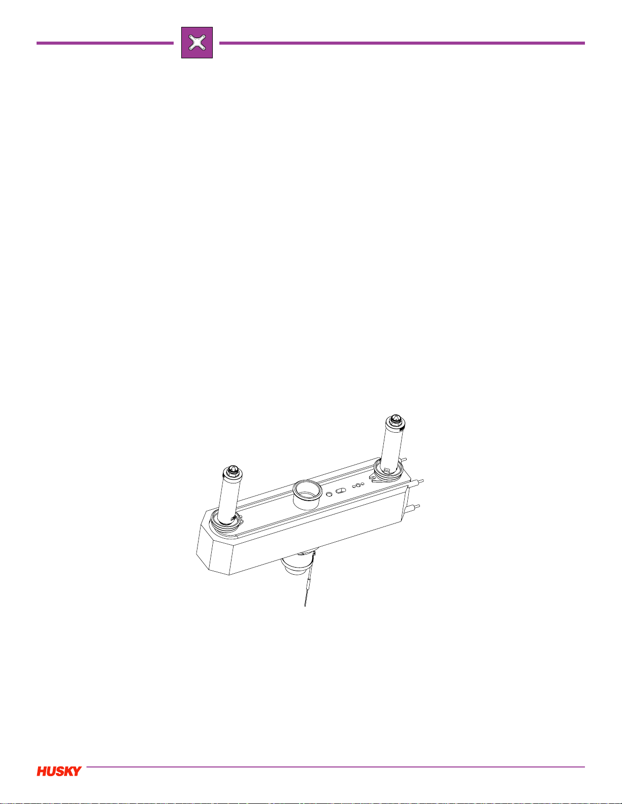
Husky PRONTO Configurable Manifold Systems
Husky’s Pronto manifolds are a line of configurable manifold systems which have all the features of our fully custom
systems minus plates and are offered at lower cost with faster deliveries. Pronto manifold systems provide far greater
flexibility than off-the-shelf or pre-engineered manifold systems. Key features include:
• 2, 4, and 8 Drop configurations
• Infinitely flexible nozzle spacing within upper and lower limits
• Three nozzle sizes (Ultra 500, Ultra 750, and Ultra 1000)
• Sixteen different gating styles including valve gate and thermal gate options
• Every application is reviewed and channel sizes are optimized for the application
• Suitable for a wide range of resins including engineering and filled resins
• Used in a broad variety of markets including housewares, closures, electronics, automotive, medical and more
• Lower cost than custom systems
• Faster delivery than custom systems
This brochure provides information needed to do a preliminary layout of a mold using a Pronto manifold system. For
information about Pronto complete hot runner systems, including plate drawings and standard feature locations please
visit our web site www.hotrunners.com.
Pronto manifold systems come complete with heated sprue bushing, nozzles, all necessary heaters and thermocouples,
associated hardware, and wire clamps. Locating ring and electrical connectors are available upon request.
The resin to be processed should be reviewed with the material compatibility chart on www.hotrunners.com. This will
determine if the application being considered is suitable for the Pronto manifold and nozzle/gating combination. The
appropriate melt channel sizes will be selected by Husky based on the resin and part information provided.
Please confirm all dimensions and nozzle suitability by contacting Husky.
1
2003.11
Page 3
PRONTO
PRONTO Manifold System Selection
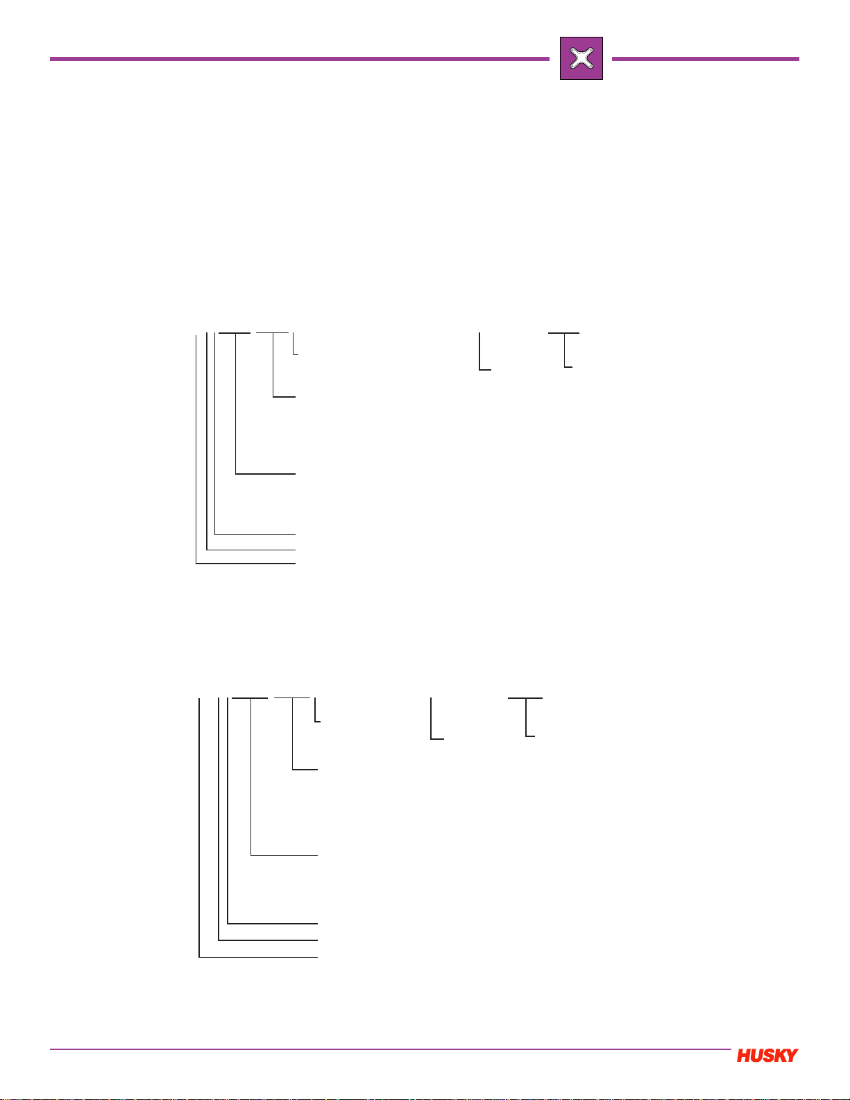
To configure Pronto Manifold Systems follow the three simple steps be low.
1 Determine the nozzle pitch required for the mold design and ensure that it is within the allowable range for the desired
size of plates
2 Select the nozzle size and gating method best suited for your application
3 Select the desired nozzle length based on L -dimension range available for the selected gating style
For example, with an Ultra 750 4-L type manifold with a pitch of 72.35 mm and 221.80mm using valve gated VG tips and
44.45 mm L -dimension, order:
MS7504L072.35/221.80M-VG044.45
MS750
4L072.35/221.80M
Always "M" for
metric
Y-dimension (for 4H/4LTypes only center of
manifold to outer drop in
mm, two decimals)
X-dimension (center of
manifold to outer drop in
mm, two decimals)
VG 044.45
Gate style
L- dimension
(in mm, two
decimals)
A, B, H, T, N or L Type manifold
Number of drops
Nozzle size
NOTE: Metric orders will receive metric hardware
For example with an Ultra 750 4-L type mani fold with a pitch of 2.125" an d 3.875" using thermal gated HT tip s and 2.375" L
-dimension order:
MS7504L1.125/3.875I-HT2.375
MS750
4L 2.125 / 3.875 I
HT 2.375
Always "I" for
Imperial
Y-dimension (for 4H/4LTypes only center of
manifold to outer drop in
inches, three decimals)
X-dimension (center of
manifold to outer drop in
inches, three decimals)
A, B, H or L Type manifold
Number of drops
Nozzle size
Gate style
L- dimension
(in inches,
three
decimals)
NOTE: Imperial orders will receive imperial hardware
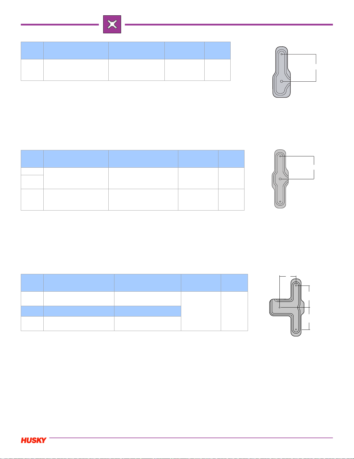
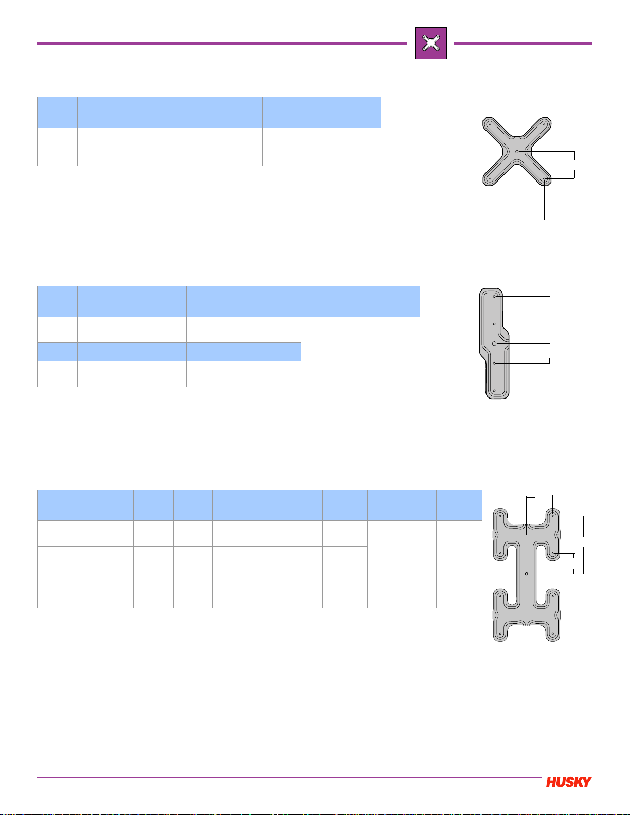
PRONTO 1 Drop I-Type Manifold (U1000 Only)
Please confirm all dimensions and nozzle suitability by contacting Husky.
2003.11
2
Page 4
PRONTO
Nozzle Minimum Pitch (X) Maximum Pitch (X)
1000
HT/TS 55mm (2.165")
VG/VX 74mm (2.913")
695mm (27.362")
PRONTO 2 Drop A-Type Manifolds
Nozzle Minimum Pitch (X) Maximum Pitch (X)
500
750
1000
HT/TS 60mm (2.363")
VG/VX 70mm (2.756")
HT/VG 55mm (2.165")
VG/VX 74mm (2.913")
366mm (14.409")
HT/VG 362mm (14.252")
VG/VX 362mm (14.252")
Number of
T/C’s
1 T/C Mounted
Through Mani-
fold Plate
Number of
T/C’s
1 T/C Mounted
Through Mani-
fold Plate
1 T/C Mounted
Through Mani-
fold Plate
Electrical
Zones
X
4-5
Electrical
Zones
X
4
4
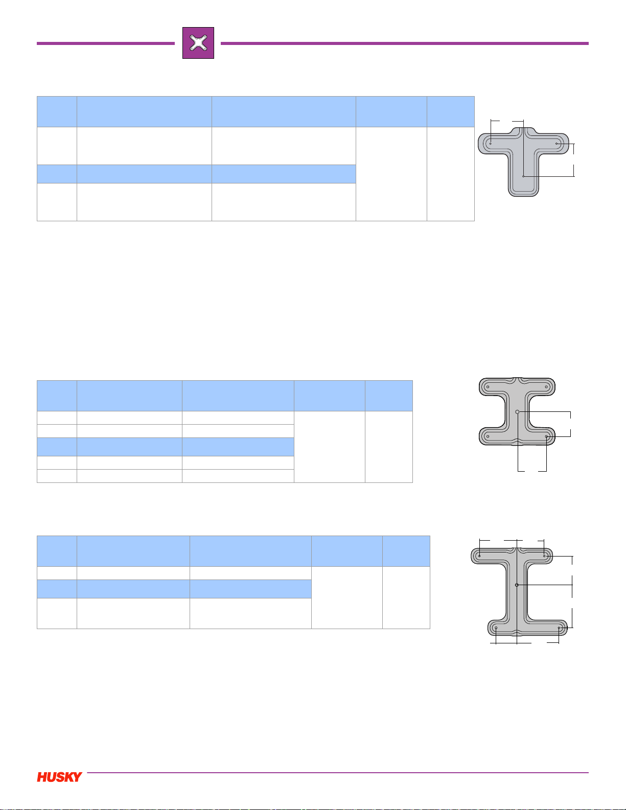
PRONTO 2 Drop T-Type Manifold
Nozzle Minimum Pitch (X1/X2) Maximum Pitch (X1/X2)
1000
1000
HT/TS 53mm (2.087")
VG/VX 53mm (2.087")
Minimum Pitch (Y) Maximum Pitch (Y)
HT/TS 53mm (2.087")
VG/VX 53mm (2.087")
HT/TS 362mm (14.252")
VG/VX 362mm (14.252")
HT/TS 200mm (7.874")
VG/VX 200mm (7.874")
Number of
T/C’s
1 T/C Mounted
Through Mani-
fold Plate
Electrical
Zones
4
Y
X1
X2
Please confirm all dimensions and nozzle suitability by contacting Husky.
3
2003.11
Page 5
PRONTO
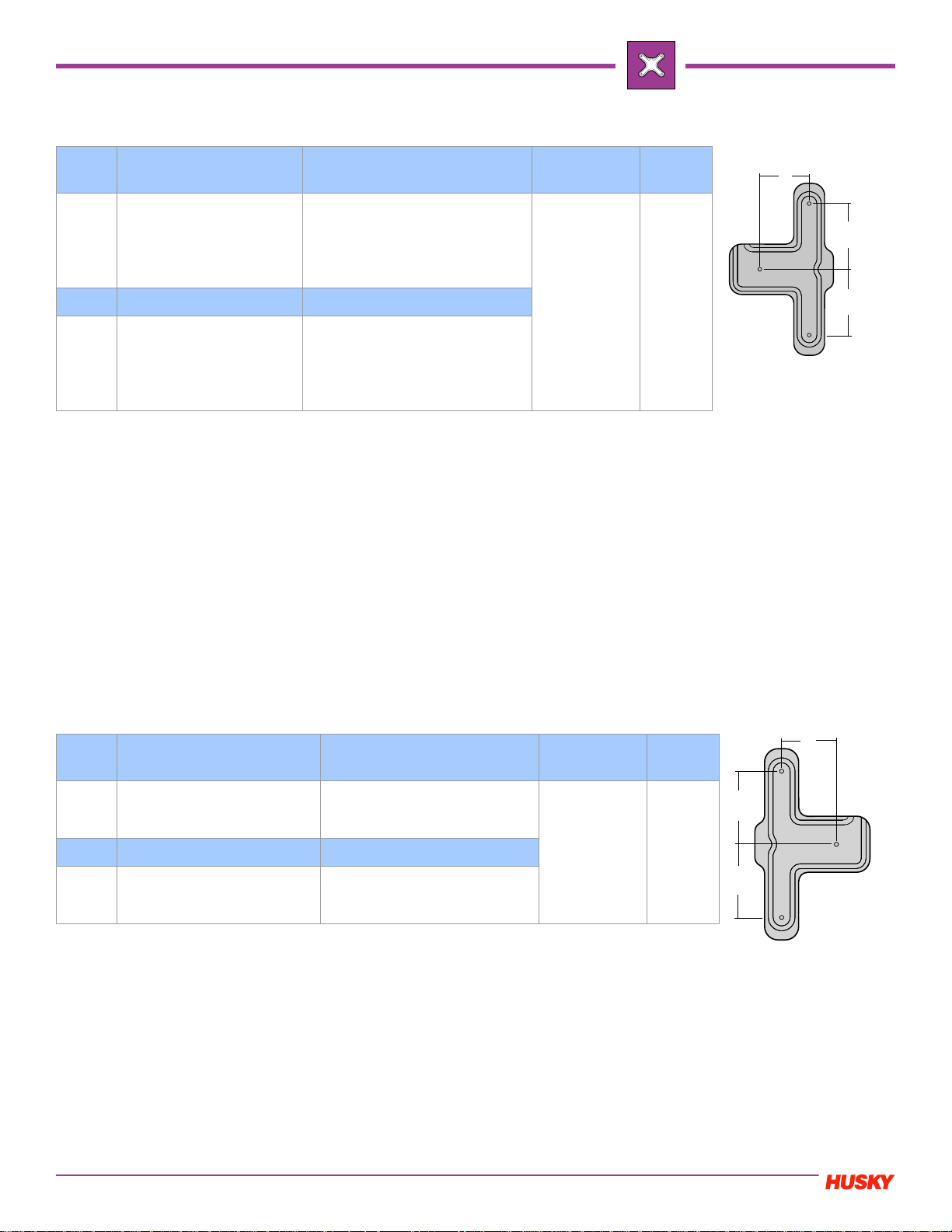
PRONTO 2 Drop T-Type Manifold (Type I)
Nozzle Minimum Pitch (X1/X2) Maximum Pitch (X1/X2)
Number of
T/C’s
Electrical
Zones
HT 500 12.7mm (0.500")
HT 500 350.0mm (13.780")
HT/TS 750 350.0mm (13.780")
VG 500/750 350.0mm (13.780")
HT 500 200.0mm (7.874")
HT/TS 750 200.0mm (7.874")
VG 500/750 200.0mm (7.874")
1 or T/C
Mounted
Through Mani-
fold Plate
4 or 5
500/750
500/750
HT/TS 750 22.5mm
(0.886")
VG 500/750 25.0mm
(0.984")
Minimum Pitch (Y) Maximum Pitch (Y)
HT 500 25.4mm (1.000")
HT/TS 750 25.4mm
(1.000")
VG 500/750 25.4mm
(1.000")
NOTE: These values are absolute. However, these values cannot be combined otherwise interference will result
(i.e. X=25.0 and Y=25.4 is incompatible). To verify that your pitch is acceptable, refer to the table below and solve
for X & Y using the following calculation:
U500VG / U750VG / U750HT
X + 1.47Y - 83.7 >= 0
U500HT
X + 1.47Y - 65.3 >= 0
If X and Y both satisfy the equation, then the pitch and sprue offset values can be incorporated into Pronto 2T.
Y
X
X
PRONTO 2 Drop T-Type Manifold (Type II)
Nozzle Minimum Pitch (X1/X2) Maximum Pitch (X1/X2)
500/750
HT 500 12.7mm (0.500")
HT/TS 750 22.5mm (0.886")
VG 500/750 25.0mm (0.984")
HT 500 350.0mm (13.780")
HT/TS 750 350.0mm (13.780")
VG 500/750 350.0mm (13.780")
Minimum Pitch (Y) Maximum Pitch (Y)
HT 500 25.4mm (1.000")
500/750
HT/TS 750 25.4mm (1.000")
VG 500/750 25.4mm (1.000")
NOTE: These values are absolute. However, these values cannot be combined otherwise interference will result
(i.e. X=25.0 and Y=25.4 is incompatible). To verify that your pitch is acceptable, refer to the table below and solve
for X & Y using the following calculation:
U500VG / U750VG / U750HT
X + 1.47Y - 83.7 >= 0
U500HT
X + 1.47Y - 65.3 >= 0
If X and Y both satisfy the equation, then the pitch and sprue offset values can be incorporated into Pronto 2T.
HT 500 200.0mm (7.874")
HT/TS 750 200.0mm (7.874")
VG 500/750 200.0mm (7.874")
Number of
T/C’s
1 or T/C
Mounted
Through Mani-
fold Plate
Electrical
Zones
4 or 5
Y
X
X
2003.11
Please confirm all dimensions and nozzle suitability by contacting Husky.
4
Page 6
PRONTO 2 Drop T-Type Manifold (Type III)
PRONTO
Nozzle
Minimum Pitch
(X1/X2)
HT 500 12.7mm (0.500")
HT/TS 750 22.5mm (0.886")
VG 500/750 25.0mm (0.984")
HT/TS 750 350.0mm (13.780")
VG 500/750 350.0mm (13.780")
Minimum Pitch (Y) Maximum Pitch (Y)
HT 500 25.4mm (1.000")
HT/TS 750 25.4mm (1.000")
VG 500/750 25.4mm (1.000")
NOTE: These values are absolute. However, these values cannot be combined otherwise interference will result
(i.e. X=25.0 and Y=25.4 is incompatible). To verify that your pitch is acceptable, refer to the table below and solve
for X & Y using the following calculation:
U500VG / U750VG / U750HT
X + 1.47Y - 83.7 >= 0
U500HT
X + 1.47Y - 65.3 >= 0
If X and Y both satisfy the equation, then the pitch and sprue offset values can be incorporated into Pronto 2T.
VG 500/750 200.0mm (7.874")
Maximum Pitch
(X1/X2)
HT 500 350.0mm (13.780")
HT 500 200.0mm (7.874")
HT/TS 750 200.0mm (7.874")
Number of
T/C’s
1 or T/C
Mounted
Through Mani-
fold Plate
Electrical
Zones
4 or 5
PRONTO 4 Drop H-Type Manifolds
Nozzle Minimum Pitch (X) Maximum Pitch (X)
Number of
T/C’s
Electrical
Zones
X
X
X
Y
500/750 50mm (1.969") 211mm (8.307")
1000 53mm (2.0 87 ") 362mm (14.252")
Minimum Pitch (Y) Maximum Pitch (Y)
500/750 50mm (1.969") 331mm (13.031")
1000 53mm (2.087") 200mm (7.874")
1 or 2 T/C
Mounted
Through Mani-
fold/Backing
Plate (If Req’d)
PRONTO 4 Drop N-Type Manifolds
Nozzle Min Pitch (X1/X2/X3/X4) Ma x Pit ch (X 1X 2/X3/X4)
1000 53mm (2.087") 362mm (14.252") 1 or 2 T/C’s
Min Pitch (Y1/Y2) Max Pitch (Y1/Y2)
1000 53mm (2.087") 200mm (7.874")
Number of
T/C’s
Mounted
Through Mani-
fold/Backing
Plate (If Req’d)
6 or 7
Electrical
Zones
6 or 7
X3
X1
Y
X
X2
Y1
Y2
X4
Please confirm all dimensions and nozzle suitability by contacting Husky.
5
2003.11
Page 7
PRONTO
PRONTO 4 Drop A-Type Manifolds
Nozzle Minimum Pitch (X)Maximum Pitch (X)
Number of
1 T/C Mounted
500/750 50mm (1.969") 180mm (7.087")
Through Mani-
PRONTO 4 Drop L-Type Manifolds
Nozzle Minimum Pitch (X) Maximum Pitch (X)
500/750
500/750
HT/TS 60mm (2.363")
VG/VX 70mm (2.756")
Minimum Pitch (Y) Maximum Pitch (Y)
HT/TS 105mm (4.134")
VG/VX 127mm (5.000")
HT/TS 316mm (12.441")
VG/VX 304mm (11.969")
361mm (14.212")
T/C’s
fold Plate
Number of
1 T/C Mounted
Manifold Plate
Electrical
Zones
T/C’s
Through
6
Electrical
Zones
6
X
X
Y
X
NOTE: For HT/TS Y-dimension must be 45mm (1.772") greater than X-dimension
NOTE: For VG/VX Y-dimension must be 57mm (2.244") greater than X-dimension
PRONTO 8 Drop H-Type Manifolds
Nozzle Min X Max X Min Y1 Max Y1 Min Y2 Max Y2
HT 500
HT 750
VG 500/750
73mm
(0.708")
73mm
(0.886")
73mm
(0.984")
211mm
(8.307")
211mm
(8.307")
211mm
(8.307")
61.3mm
(1.752")
61.3mm
(1.693")
61.3mm
(2.165")
Y2-62mm
(1.000")
Y2-62mm
(1.771")
Y2-62mm
(1.968")
Y1+62mm
(1.000")
Y1+62mm
(1.771")
Y1+62mm
(1.968")
331mm
(13.031")
331mm
(13.031")
331mm
(13.031")
Number of
T/C’s
2 T/C Mounted
Through Man
Plate
2 T/C Mounted
Through Back
Plate (when
required)
Electrical
Zones
11 or 13
X
Y2
Y1
2003.11
Please confirm all dimensions and nozzle suitability by contacting Husky.
6
Page 8
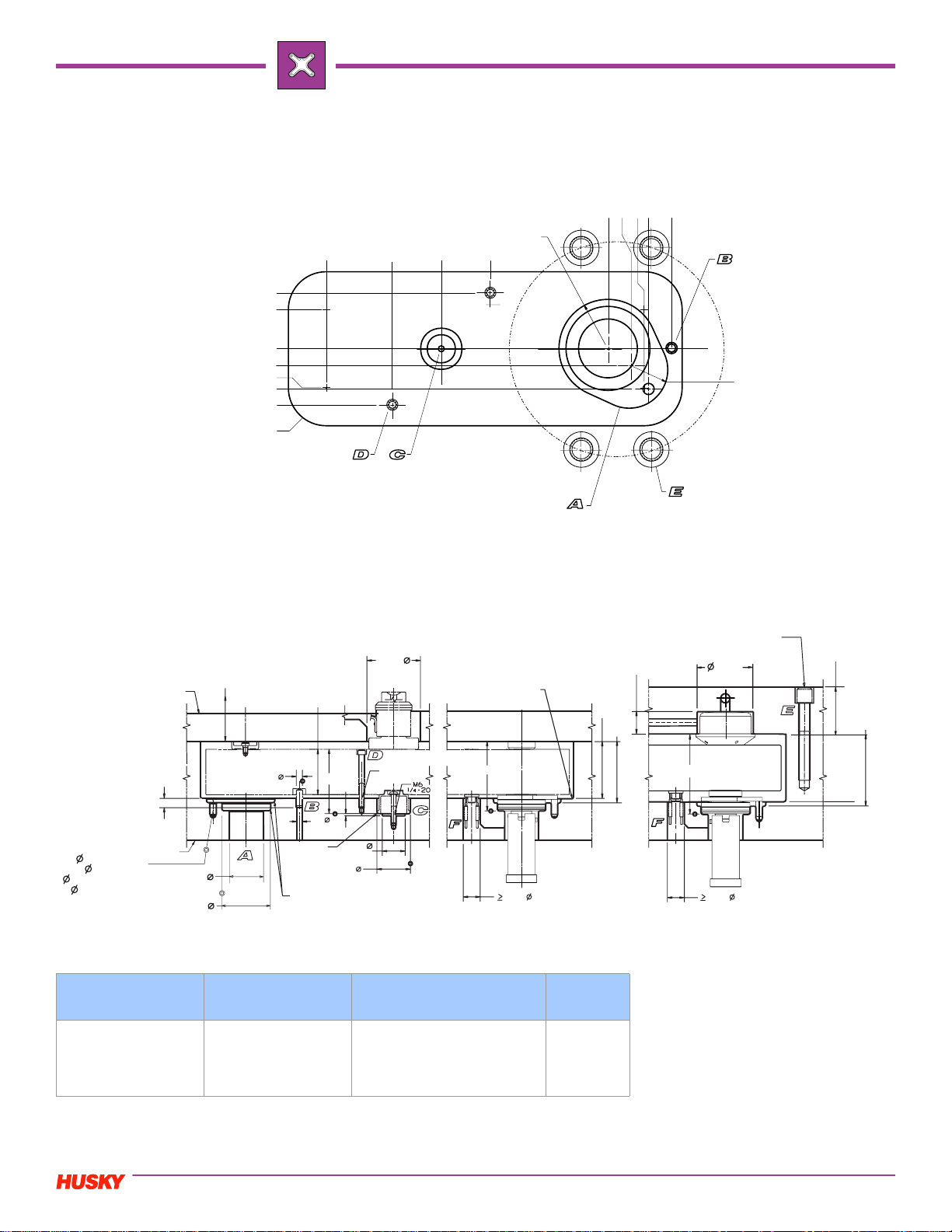
1 Drop
PRONTO 1 Drop I-Type Manifolds (Ultra 1000 Only)
0,000 [.0000]
40,0 [1.57]
28,0 [1.10]
0,000 [.0000]
15,2 [0.60]
28,0 [1.10]
29,0 [1.14]
40,0 [1.57]
R 27,0 [1.06]
(4)
113,0 [4.45]
35,0 [1.38]
RAD 35,0
[1.38]
35,0 [1.38]
X + 15,2 [0.60]
X
X + 45,0 [1.77]
X + 28,0 [1.10]
X + 29,00 [1.142]
RAD 27,5
[1.08]
PRONTO
View From
Injection Side
BK-PLT
12.5 [0.49]
6.8 x 17.0 DP.
[ .27 x .67 DP.]
8.03 +0.03 x 15.0 DP.
[ .32 +.0001 x .59 DP.]
MF-PLT
42.0 [1.66]
60.01 +0.03 [2.36 +.0001]
40.0
[1.57]
8.000 +0.015
[.3150 +.0006]
Plate features are noted on plan view and correspond to features in section view below.
M16 [5/8-11 UNC]
(3 Bolts per drop
recommeded)
For HT / TS
For HT / TS
75.0 [2.95]
80.8 [3.18]
26.8 [1.06]
*B
68.00
[2.68]
22.2
[.88]
T/C MF-PLT
60.00
[2.36]
*C
6.8
[.27]
MAX 1.5R
[.06]
44.01 +0.03
[1.733 +.001]
R 1.5 [.06] MAX
3.0 MIN
[.12]
30.0
[1.18]
70.00
[2.76]
M6
-20
1/4
RAD 3.0
[.12]
(2)
*B
22.2
[.88]
T/C MF-PLT THRU HOLE
FOR X> 87 mm
For VG / VX
60.00
[2.36]
79.0 [3.11]
92.6 [3.65]
Minimum Pitch (X) Maximum Pitch (X) Number of T/C’s
HT/TS 55mm
(2.165")
VG/VX 74mm
695mm (27.362")
1 T/C Mounted Through
Manifold Plate
(2.913")
Please confirm all dimensions and nozzle suitability by contacting Husky.
7
Electrical
Zones
3
T/C : Thermocouple
BK - PLT : Manifold Backing Plate
MF - PLT : Manifold Plate
X : Pitch X Value
Y : Pitch Y Value
R, RAD : Radius
C : Center Insulator Bore Depth*
B : Nozzle Bore Depth*
*Refer to calculator on www.hotrunners.com
2003.11
Page 9
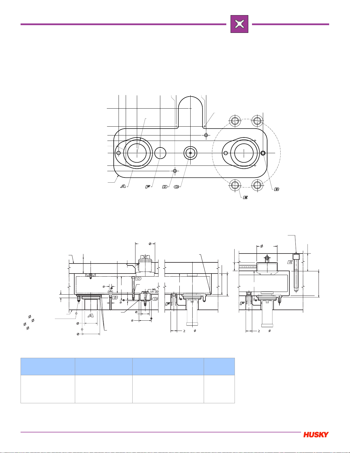
PRONTO 2 Drop
PRONTO 2 Drop A-Type Manifolds (Ultra 1000)
X - 52,2 [X - 2 .06]
IF X<100,0 [3.94]
X + 25,0 [.98]
X + 41,00 [1.614]
X
T/C IS SIDE MOUNTED
32,0 [1.26]
35,0 [1.38]
0,000 [.0000]
32,0 [1.26]
35,0 [1.38]
View From
Injection Side
BK-PLT
100,0 [3.94]
60,0 [2.36]
40,0 [1.58]
28,0 [1.10]
RAD 27,5
[1.08]
0,000 [0.0000]
28,0 [1.10]
40,0 [1.58]
RAD 27,0 (5)
[1.06]
RAD 35,0
[1.38]
RAD 5,0 [.20]
(2)
Plate features are noted on plan view and correspond to features in section view below.
For HT / TS
For HT / TS
75.0 [2.95]
80.8 [3.18]
26.8 [1.06]
40.0
[1.57]
60.00
[2.36]
70.00
[2.76]
RAD 3.0
[.12]
X + 45,0 [1.77]
M16 [5/8-11 UNC]
(4 Bolts per drop
recommended)
68.00
[2.68]
For VG / VX
60.00
[2.36]
79.0 [3.11]
92.6 [3.65]
6.8 x 17.0 DP.
[ .27 x .67 DP.]
8.03 +0.03 x 15.0 DP.
[ .32 +.0001 x .59 DP.]
60.01 +0.03 [2.36 +.0001]
MF-PLT
12.5 [0.49]
42.0 [1.66]
8.000 +0.015
[.3150 +.0006]
*C
6.8
[.27]
MAX 1.5R
[.06]
44.01 +0.03
[1.733 +.001]
R 1.5 [.06] MAX
3.0 MIN
[.12]
30.0
[1.18]
M6
-20
1/4
(2)
*B
Minimum Pitch (X) Maximum Pitch (X) Number of T/C’s
HT/TS 55mm
(2.165")
VG/VX 74mm
(2.913")
2003.11
HT/TS 362mm
(14.252")
VG/VX 362mm
1 T/C Mounted Through
Manifold Plate
(14.252")
Please confirm all dimensions and nozzle suitability by contacting Husky.
8
22.2
[.88]
T/C MF-PLT THRU HOLE
FOR X> 87 mm
Electrical
Zones
4
*B
22.2
[.88]
T/C MF-PLT
T/C : Thermocouple
BK - PLT : Manifold Backing Plate
MF - PLT : Manifold Plate
X : Pitch X Value
Y : Pitch Y Value
R, RAD : Radius
C : Center Insulator Bore Depth*
B : Nozzle Bore Depth*
*Refer to calculator on www.hotrunners.com
Page 10

2 Drop
PRONTO 2 Drop A-Type Manifolds (Ultra 750)
T/C for X ≤ 87mm
(3.452")
T/C for X > 87mm (3.452")
Manifold Heater
#1A (Clamp)
#1B (Injection)
PRONTO
View From
Injection Side
For VG /VX
For HT / TS
Minimum Pitch (X) Maximum Pitch (X) Number of T/C’s
HT/TS 60mm
(2.363")
VG/VX 70mm
(2.756")
366mm (14.409")
Plate features are noted on plan view and correspond to features in section view below.
Contact Husky to verfiy T/C thru hole location.
Plate features are noted on plan view and correspond to features in section view below.
MIN
MAX
MAX
1 T/C Mounted Through
Manifold Plate
Please confirm all dimensions and nozzle suitability by contacting Husky.
9
THRU HOLE FOR
T
X>87 mm
Electrical
Zones
4
For HT / TS
Recommeded drop bolt circle
For VG /VX
M16 [5/8-11 UNC]
For HT / TS
(3 Bolts per drop
recommeded)
T/C : Thermocouple
BK - PLT : Manifold Backing Plate
MF - PLT : Manifold Plate
X : Pitch X Value
Y : Pitch Y Value
R, RAD : Radius
C : Center Insulator Bore Depth*
B : Nozzle Bore Depth*
*Refer to calculator on
www.hotrunners.com
For VG /VX
2003.11
Page 11

PRONTO 2 Drop
PRONTO 2 Drop A-Type Manifolds (Ultra 500)
Manifold Heater
#1A (Clamp)
#1B (Injection)
T/C for X ≤ 87mm
(3.452")
T/C for X > 87mm
(3.452")
View From
Injection Side
Plate features are noted on plan view and correspond to features in section view below.
Recommeded drop bolt circle
Contact Husky to verfiy T/C thru hole location.
Plate features are noted on plan view and correspond to features in section view below.
For VG /VX
For HT / TS
MIN
MAX
Sharp
Minimum Pitch (X) Maximum Pitch (X) Number of T/C’s
HT/TS 60mm
(2.363")
VG/VX 70mm
366mm (14.409")
1 T/C Mounted Through
Manifold Plate
(2.756")
THRU HOLE
FOR X > 87 mm
Electrical
Zones
4
For VG /VX
For HT / TS
M12 [1/2-13 UNC]
(3 Bolts per drop
recommeded)
T/C : Thermocouple
BK - PLT : Manifold Backing Plate
MF - PLT : Manifold Plate
X : Pitch X Value
Y : Pitch Y Value
R, RAD : Radius
C : Center Insulator Bore Depth*
B : Nozzle Bore Depth*
*Refer to calculator on
www.hotrunners.com
For VG /VX
2003.11
Please confirm all dimensions and nozzle suitability by contacting Husky.
10
Page 12

2 Drop
X
PRONTO 2 Drop T-Type Manifold Type I (Ultra 1000)
[1.614]
47,0 [1.85]
41,0 [1.61]
30,0 [1.18]
0,000 [.0000]
14,0 [0.55]
Contact Husky
for T/C Location
51,0 [2.01]
Y + 39,32 [1.548]
X + 41,00
X + 28,0 [1.10]
X + 21,5 [.85]
R 10,0 (2)
[0.39]
Y
X
61,0 [2.40]
30,0 [1.18]
24,0 [0.95]
0,000 [.0000]
24,0 [0.95]
PRONTO
31.45 [1.238]
RAD 27,5
[1.08]
RAD 35,0
[1.38]
View From
Injection Side
BK-PLT
12.5 [0.49]
6.8 x 17.0 DP.
[ .27 x .67 DP.]
8.03 +0.03 x 15.0 DP.
[ .32 +.0001 x .59 DP.]
MF-PLT
42.0 [1.66]
60.01 +0.03 [2.36 +.0001]
Y + 130,0 [5.12]
R 27,0 (6)
[1.06]
Contact Husky to verfiy T/C thru hole location.
Plate features are noted on plan view and correspond to features in section view below.
For HT / TS
For HT / TS
75.0 [2.95]
80.8 [3.18]
26.8 [1.06]
40.0
[1.57]
8.000 +0.015
[.3150 +.0006]
60.00
[2.36]
*C
6.8
[.27]
MAX 1.5R
[.06]
44.01 +0.03
[1.733 +.001]
R 1.5 [.06] MAX
3.0 MIN
[.12]
30.0
[1.18]
70.00
[2.76]
M6
-20
1/4
RAD 3.0
[.12]
(2)
*B
22.2
[.88]
T/C MF-PLT THRU HOLE
FOR X> 87 mm
M16 [5/8-11 UNC]
(3 Bolts per drop
68.00
[2.68]
*B
22.2
[.88]
T/C MF-PLT
recommeded)
For VG / V
60.00
[2.36]
79.0 [3.11]
92.6 [3.65]
Minimum Pitch (X) Maximum Pitch (X) Number of T/C’s
53mm (2.087") 362mm (14.252")
Minimum Pitch (Y) Maximum Pitch (Y)
53mm (2.087") 200mm (7.874")
Please confirm all dimensions and nozzle suitability by contacting Husky.
1 or 2 T/C Mounted
Through Manifold
Plate
11
Electrical
Zones
4 or 5
T/C : Thermocouple
BK - PLT : Manifold Backing Plate
MF - PLT : Manifold Plate
X : Pitch X Value
Y : Pitch Y Value
R, RAD : Radius
C : Center Insulator Bore Depth*
B : Nozzle Bore Depth*
*Refer to calculator on
www.hotrunners.com
2003.11
Page 13

PRONTO 2 Drop
PRONTO 2 Drop T-Type Manifold Type I (Ultra 750)
22,65 [0.892]
26,000 [1.0236]
0,000 [0.000]
- 24,00 [- 0.945]
OPERATOR
24,0 [0.94]
66,0 [2.60]
61,1 [2.41] (2)
RAD 22,0 [0.87] (2)
RAD 15,0 [0.59]
RAD 27,0 [1.06] (8)
R 55,0 [2.17]
Recommeded drop bolt circle
TOP
View From
Injection Side
Y + 55,0 [+ 2.165]
Y + 38,0 [+ 1.496]
Y + 33,72 [+ 1.328]
Y + 25,5 [+ 1.004]
Y + 23,0 [+ 0.906]
Y + 6,0 [+ 0.236]
Y - 6,0 [- 0.236]
Y - 38,0 [- 1.496]
Y - 48,0 [- 1.890]
0,000 [0.0000]
- 1,0 [- 0.04]
- 31,65 [- 1.246]
- 33,0 [- 1.30]
-100,0 [3.94]
- 56,0 [- 2.20]
Y
Min > 10,0 [0.394]
X
X + 15,0 [0.591]
RAD 5,0 [0.20] (2)
Contact Husky to verify T/C thru hole location.
Plate features are noted on plan view and correspond to features in section view below.
For VG /VX
For HT / TS
MIN
MAX
MAX
Minimum Pitch (X1/X2) Maximum Pitch (X1/X2)
HT 500 12.7mm (0.500")
HT/TS 750 22.5mm (0.886")
VG 500/750 25.0mm (0.984")
HT 500 350.0mm (13.780")
HT/TS 750 350.0mm (13.780")
VG 500/750 350.0mm (13.780" )
Minimum Pitch (Y) Maximum Pitch (Y)
HT 500 25.4mm (1.000")
HT/TS 750 25.4mm (1.000")
VG 500/750 25.4mm (1.000")
HT 500 200.0mm (7.874")
HT/TS 750 200.0mm (7.874")
VG 500/750 200.0mm (7.874")
THRU HOLE FOR
X>87 mm
Number
of T/C’s
1 or 2 T/C
Mounted
Through
Manifold
Plate
For HT / TS
For VG /VX
For HT / TS
T
Electrical
Zones
4 or 5
M16 [5/8-11 UNC]
(3 Bolts per drop
recommeded)
For VG /VX
T/C : Thermocouple
BK - PLT : Manifold Backing Plate
MF - PLT : Manifold Plate
X : Pitch X Value
Y : Pitch Y Value
R, RAD : Radius
C : Center Insulator Bore Depth*
B : Nozzle Bore Depth*
*Refer to calculator on
www.hotrunners.com
2003.11
Please confirm all dimensions and nozzle suitability by contacting Husky.
12
Page 14

2 Drop
PRONTO 2 Drop T-Type Manifold Type I (Ultra 500)
-100,0 [3.94]
- 56,0 [- 2.20]
- 24,00 [- 0.945]
Y + 18,0 [+ 0.17] (2)
TOP
Y + 55,0 [+ 2.165]
Y + 38,0 [+ 1.496]
Y + 33,72 [+ 1.328]
Y + 23,0 [+ 0.906]
Y + 6,0 [+ 0.236]
Y - 6,0 [- 0.236]
Y - 38,0 [- 1.496]
Y - 48,0 [- 1.890]
0,000 [0.0000]
- 1,0 [- 0.04]
- 31,65 [- 1.246]
- 33,0 [- 1.30]
Y
Min > 10,0 [0.394]
X
X + 15,0 [0.591]
RAD 5,0 [0.20] (2)
View From
Injection Side
OPERATOR
22,65 [0.892]
26,000 [1.0236]
0,000 [0.000]
24,0 [0.94]
66,0 [2.60]
61,1 [2.41] (2)
RAD 15,0 [0.59]
RAD 27,0 [1.06] (8)
RAD 22,0 [0.87] (2)
R 55,0 [2.17]
Recommeded drop bolt circle
PRONTO
Contact Husky to verfiy T/C thru hole location.
Plate features are noted on plan view and correspond to features in section view below.
For VG /VX
For HT / TS
MIN
MAX
Sharp
Minimum Pitch (X1/X2) Maximum Pitch (X1/X2)
HT 500 12.7mm (0.500")
HT/TS 750 22.5mm (0.886")
VG 500/750 25.0mm (0.984")
HT 500 350.0mm (13.780")
HT/TS 750 350.0mm (13.780")
VG 500/750 350.0mm (13.780")
Minimum Pitch (Y) Maximum Pitch (Y)
HT 500 25.4mm (1.000")
HT/TS 750 25.4mm (1.000")
VG 500/750 25.4mm (1.000")
HT 500 200.0mm (7.874")
HT/TS 750 200.0mm (7.874")
VG 500/750 200.0mm (7.874")
THRU HOLE
FOR X > 87 mm
Number of
T/C’s
1 or 2 T/C
Mounted
Through
Manifold
Plate
For VG /VX
For HT / TS
Electrical
Zones
4 or 5
M12 [1/2-13 UNC]
(3 Bolts per drop
recommeded)
For VG /VX
T/C : Thermocouple
BK - PLT : Manifold Backing Plate
MF - PLT : Manifold Plate
X : Pitch X Value
Y : Pitch Y Value
R, RAD : Radius
C : Center Insulator Bore Depth*
B : Nozzle Bore Depth*
*Refer to calculator
on www.hotrunners.com
Please confirm all dimensions and nozzle suitability by contacting Husky.
13
2003.11
Page 15

PRONTO 2 Drop
PRONTO 2 Drop T-Type Manifold Type II (Ultra 750)
RAD 27,0 [1.06] (8)
+ 33,0 [+ 1.30]
+ 31,65 [+ 1.246]
+ 1,0 [+ 0.04]
0,000 [0.0000]
Min > 10,0 [0.394]
R 55,0 [2.17]
TOP
Y + 48,0 [+ 1.890]
Y + 38,0 [+ 1.496]
Y + 6,0 [+ 0.236]
Y - 23,0 [- 0.906]
Y - 25,5 [- 1.004]
Y - 33,72 [- 1.328]
Y - 38,0 [- 1.496]
Y - 55,0 [- 2.165]
Y - 6,0 [- 0.236]
RAD 5,0 [0.20] (2)
Y
RAD 15,0 [0.59]
Recommeded drop bolt circle
View From
Injection Side
For HT / TS
66,0 [2.60]
61,1 [2.41] (2)
RAD 22,0 [0.87] (2)
X
X + 15,0 [0.591]
-100,0 [- 3.94]
- 56,0 [- 2.20]
OPERATOR
0,000 [0.000]
22,65 [0.892]
- 24,00 [- 0.945]
24,0 [0.94]
26,000 [1.0236]
Contact Husky to verfiy T/C thru hole location.
Plate features are noted on plan view and correspond to features in section view below.
For VG /VX
For HT / TS
For HT / TS
For VG /VX
MIN
MAX
MAX
THRU HOLE FOR
T
X>87 mm
M16 [5/8-11 UNC]
(3 Bolts per drop
recommeded)
For VG /VX
Minimum Pitch (X1/X2) Maximum Pitch (X1/X2)
HT 500 12.7mm (0.500")
HT/TS 750 22.5mm (0.886")
VG 500/750 25.0mm (0.984")
HT 500 350.0mm (13.780")
HT/TS 750 350.0mm (13.780")
VG 500/750 350.0mm
(13.780")
Minimum Pitch (Y) Maximum Pitch (Y)
HT 500 25.4mm (1.000")
HT/TS 750 25.4mm (1.000")
VG 500/750 25.4mm (1.000")
2003.11
HT 500 200.0mm (7.874")
HT/TS 750 200.0mm (7.874")
VG 500/750 200.0mm (7.874")
Please confirm all dimensions and nozzle suitability by contacting Husky.
Number of
14
T/C’s
1 or 2 T/C
Mounted
Through
Manifold
Plate
Electrical
Zones
4 or 5
T/C : Thermocouple
BK - PLT : Manifold Backing Plate
MF - PLT : Manifold Plate
X : Pitch X Value
Y : Pitch Y Value
R, RAD : Radius
C : Center Insulator Bore Depth*
B : Nozzle Bore Depth*
*Refer to calculator
on www.hotrunners.com
Page 16

2 Drop
PRONTO 2 Drop T-Type Manifold Type II (Ultra 500)
+ 33,0 [+ 1.30]
+ 31,65 [+ 1.246]
+ 1,0 [+ 0.04]
0,000 [0.0000]
Min > 10,0 [0.394]
TOP
Y + 48,0 [+ 1.890]
Y + 38,0 [+ 1.496]
Y + 18,0 [+ 0.17]
Y + 6,0 [+ 0.236]
Y - 23,0 [- 0.906]
Y - 33,72 [- 1.328]
Y - 38,0 [- 1.496]
Y - 55,0 [- 2.165]
Y - 6,0 [- 0.236]
Y
RAD 5,0 [0.20] (2)
RAD 27,0 [1.06] (8)
RAD 15,0 [0.59]
R 55,0 [2.17]
Recommeded drop bolt circle
PRONTO
View From
Injection Side
Sharp
66,0 [2.60]
61,1 [2.41] (2)
RAD 22,0 [0.87] (2)
X
X + 15,0 [0.591]
-100,0 [- 3.94]
- 56,0 [- 2.20]
OPERATOR
0,000 [0.000]
22,65 [0.892]
- 24,00 [- 0.945]
24,0 [0.94]
26,000 [1.0236]
Plate features are noted on plan view and correspond to features in section view below.
For VG /VX
MAX
MIN
THRU HOLE
FOR X > 87 mm
For HT / TS
M12 [1/2-13 UNC]
(3 Bolts per drop
recommeded)
For VG /VX
Minimum Pitch (X1/X2) Maximum Pitch (X1/X2)
HT 500 12.7mm (0.500")
HT/TS 750 22.5mm (0.886")
VG 500/750 25.0mm (0.984")
HT 500 350.0mm (13.780")
HT/TS 750 350.0mm (13.780")
VG 500/750 350.0mm (13.780")
Minimum Pitch (Y) Maximum Pitch (Y)
HT 500 25.4mm (1.000")
HT/TS 750 25.4mm (1.000")
VG 500/750 25.4mm (1.000")
HT 500 200.0mm (7.874")
HT/TS 750 200.0mm (7.874")
VG 500/750 200.0mm (7.874")
Please confirm all dimensions and nozzle suitability by contacting Husky.
15
Number of
T/C’s
1 or 2 T/C
Mounted
Through
Manifold
Plate
Electrical
Zones
4 or 5
T/C : Thermocouple
BK - PLT : Manifold Backing Plate
MF - PLT : Manifold Plate
X : Pitch X Value
Y : Pitch Y Value
R, RAD : Radius
C : Center Insulator Bore Depth*
B : Nozzle Bore Depth*
*Refer to calculator on
www.hotrunners.com
2003.11
Page 17

PRONTO 2 Drop
PRONTO 2 Drop T-Type Manifold Type III (Ultra 750)
TOP
X
View From
Injection Side
Y + 93,0 [3.66]
Y + 59,2 [2.33]
Y + 38,0 [1.50] (2)
Y + 33,72 [1.328]
Y + 25,50 [1.004]
OPERATOR
-31.65 [-1.246]
- 33,0 [-1.30] (2)
Y + 6,0 [0.24]
Y - 6,0 [0.24]
Y - 43,0 [1.69]
0,000 [0.000]
X + 15,0 [0.59]
Y
- 24,00 [- 0.945] (2)
0,000 [0.000]
22,65 [0.892]
53,2 [2.10] (2)
61,0 [2.40] (2)
26,000 [1.0236]
32,0 [1.26] (2)
RAD 5,000 [0.1969] (4)
RAD 10,000 [0.3937] (2)
RAD 27,0 [1.0630] (7)
R 55,0 [2.17]
Recommeded drop bolt circle
Plate features are noted on plan view and correspond to features in section view below.
For VG /VX
For HT / TS
MIN
MAX
MAX
Minimum Pitch (X1/X2) Maximum Pitch (X1/X2)
HT 500 12.7mm (0.500")
HT/TS 750 22.5mm (0.886")
VG 500/750 25.0mm (0.984")
HT 500 350.0mm (13.780")
HT/TS 750 350.0mm (13.780")
VG 500/750 350.0mm (13.780")
Minimum Pitch (Y) Maximum Pitch (Y)
HT 500 25.4mm (1.000")
HT/TS 750 25.4mm (1.000")
VG 500/750 25.4mm (1.000")
HT 500 200.0mm (7.874")
HT/TS 750 200.0mm (7.874")
VG 500/750 200.0mm (7.874")
THRU HOLE FOR
X>87 mm
Number of
T/C’s
1 or 2 T/C
Mounted
Through
Manifold
Plate
For VG /VX
For HT / TS
For HT / TS
T
Electrical
Zones
4 or 5
M16 [5/8-11 UNC]
(3 Bolts per drop
recommeded)
For VG /VX
T/C : Thermocouple
BK - PLT : Manifold Backing Plate
MF - PLT : Manifold Plate
X : Pitch X Value
Y : Pitch Y Value
R, RAD : Radius
C : Center Insulator Bore Depth*
B : Nozzle Bore Depth*
*Refer to calculator on www.hotrun-
2003.11
Please confirm all dimensions and nozzle suitability by contacting Husky.
16
Page 18

2 Drop
PRONTO 2 Drop T-Type Manifold Type III (Ultra 500)
X + 15,0 [0.59]
X
Y + 93,0 [3.66]
Y + 59,2 [2.33]
Y + 38,0 [1.50] (2)
Y + 33,72 [1.328]
Y + 18,0 [+ 0.17]
Y + 6,0 [0.24]
Y
Y - 6,0 [0.24]
Y - 43,0 [1.69]
OPERATOR
0,000 [0.000]
View From
Injection Side
-31.65 [-1.246]
- 33,0 [-1.30] (2)
Plate features are noted on plan view and correspond to features in section view below.
TOP
- 24,00 [- 0.945] (2)
0,000 [0.000]
22,65 [0.892]
26,000 [1.0236]
53,2 [2.10] (2)
61,0 [2.40] (2)
32,0 [1.26] (2)
RAD 27,0 [1.0630] (7)
RAD 5,000 [0.1969] (4)
RAD 10,000 [0.3937] (2)
PRONTO
R 55,0 [2.17]
Recommeded drop bolt circle
MIN
MAX
Sharp
Minimum Pitch (X1/X2) Maximum Pitch (X1/X2)
HT 500 12.7mm (0.500")
HT/TS 750 22.5mm (0.886")
VG 500/750 25.0mm (0.984")
HT 500 350.0mm (13.780")
HT/TS 750 350.0mm (13.780")
VG 500/750 350.0mm (13.780")
Minimum Pitch (Y) Maximum Pitch (Y)
HT 500 25.4mm (1.000")
HT/TS 750 25.4mm (1.000")
VG 500/750 25.4mm (1.000")
HT 500 200.0mm (7.874")
HT/TS 750 200.0mm (7.874")
VG 500/750 200.0mm (7.874")
THRU HOLE
FOR X > 87 mm
Number of
T/C’s
1 or 2 T/C
Mounted
Through
Manifold
Plate
For VG /VX
For HT / TS
Electrical
Zones
4 or 5
M12 [1/2-13 UNC]
(3 Bolts per drop
recommeded)
For VG /VX
T/C : Thermocouple
BK - PLT : Manifold Backing Plate
MF - PLT : Manifold Plate
X : Pitch X Value
Y : Pitch Y Value
R, RAD : Radius
C : Center Insulator Bore Depth*
B : Nozzle Bore Depth*
*Refer to calculator on
www.hotrunners.com
Please confirm all dimensions and nozzle suitability by contacting Husky.
17
2003.11
Page 19

PRONTO 4 Drop
PRONTO 4 Drop H-Type Manifolds (Ultra 1000)
0,000 [.0000]
X
X + 41,00 [1.614]
X + 21,5 [.85]
X + 28,0 [1.10]
56,7 [2.23]
X + 39,7 [1.56]
X + 21,0 [0.83]
X + 21,0 [1.06]
RAD 27,0 (6)
[1.06]
View From
Injection Side
Plate features are noted on plan view and correspond to features in section view below.
40.0
BK-PLT
[1.57]
Y1 + 100,0 [3.94]
Y1 + 61,7 [2.43]
Contact Husky
for T/C Location
Y1 + 22,0 [0.87]
Y1 - 13,0 [0.51]
Y1 - 17,7 [0.70]
Y1 - 52,7 [2.07]
0,000 [.0000]
Y2 - 52,7 [2.07]
Y2 - 17,7 [0.70]
Y2 - 13,0 [0.51]
Y2 + 22,0 [0.87]
60.00
Y1
Y2
[2.36]
70.00
[2.76]
RAD 3.0
[.12]
RAD 12,7 (6)
[1.06]
RAD 35,0
[1.38]
75.0 [2.95]
RAD 27,5
[1.08]
For HT / TS
For HT / TS
80.8 [3.18]
26.8 [1.06]
M16 [5/8-11 UNC]
(4 Bolts per drop
recommended)
68.00
[2.68]
60.00
[2.36]
For VG / VX
For VG / VX
79.0 [3.11]
92.6 [3.65]
M6
-20
1/4
(2)
6.8 x 17.0 DP.
[ .27 x .67 DP.]
8.03 +0.03 x 15.0 DP.
[ .32 +.0001 x .59 DP.]
60.01 +0.03 [2.36 +.0001]
MF-PLT
12.5 [0.49]
42.0 [1.66]
8.000 +0.015
[.3150 +.0006]
*C
6.8
[.27]
MAX 1.5R
[.06]
44.01 +0.03
[1.733 +.001]
R 1.5 [.06] MAX
3.0 MIN
[.12]
30.0
[1.18]
Minimum Pitch (X) Maximum Pitch (X) Number of T/C’s
53mm (2.087") 362mm (14.252")
Minimum Pitch (Y) Maximum Pitch (Y)
53mm (2.087") 200mm (7.874")
Please confirm all dimensions and nozzle suitability by contacting Husky.
2003.11
1 T/C Mounted thru MF PLT
1 T/C Mounted Thru BK
PLT (when required)
18
*B
22.2
[.88]
T/C MF-PLT THRU HOLE
FOR X> 87 mm
Electrical
Zones
6 or 7
*B
22.2
[.88]
T/C MF-PLT
T/C : Thermocouple
BK - PLT : Manifold Backing Plate
MF - PLT : Manifold Plate
X : Pitch X Value
Y : Pitch Y Value
R, RAD : Radius
C : Center Insulator Bore Depth*
B : Nozzle Bore Depth*
*Refer to calculator on
www.hotrunners.com
Page 20

4 Drop
PRONTO 4 Drop H-Type Manifolds (Ultra 750)
Manifold Heater
#1A (Clamp)
#1B (Injection)
Recommeded drop bolt circle
PRONTO
View From
Injection Side
Plate features are noted on plan view and correspond to features in section view below.
For VG /VX
For HT / TS
MIN
MAX
MAX
Minimum Pitch (X) Maximum Pitch (X) Number of T/C’s
HT/TS 50mm (1.969")
VG/VX 50mm (1.969")
Minimum Pitch (Y) Maximum Pitch (Y)
HT/TS 50mm (1.969")
VG/VX 50mm (1.969")
HT/TS 211mm (8.307")
VG/VX 211mm (8.307")
1 T/C Mounted
Through MF PLT
1 T/C Mounted
Through BK PLT
331mm (13.031")
Please confirm all dimensions and nozzle suitability by contacting Husky.
(when required)
19
THRU HOLE FOR
X>87 mm
Electrical
Zones
6 or 7
For VG /VX
For HT / TS
M16 [5/8-11 UNC]
(3 Bolts per drop
For HT / TS
T
T/C : Thermocouple
BK - PLT : Manifold Backing Plate
MF - PLT : Manifold Plate
X : Pitch X Value
Y : Pitch Y Value
R, RAD : Radius
C : Center Insulator Bore Depth*
B : Nozzle Bore Depth*
*Refer to calculator on
www.hotrunners.com
recommeded)
For VG /VX
2003.11
Page 21

PRONTO 4 Drop
PRONTO 4 Drop H-Type Manifolds (Ultra 500)
Manifold Heater
#1A (Clamp)
#1B (Injection)
Recommeded drop bolt circle
View From
Injection Side
Plate features are noted on plan view and correspond to features in section view below.
MIN
MAX
Sharp
Minimum Pitch (X) Maximum Pitch (X) Number of T/C’s
HT/TS 50mm (1.969")
VG/VX 50mm (1.969")
Minimum Pitch (Y) Maximum Pitch (Y)
HT/TS 50mm (1.969")
VG/VX 50mm (1.969")
2003.11
HT/TS 211mm (8.307")
VG/VX 211mm (8.307")
1 T/C Mounted
Through MF PLT
1 T/C Mounted
Through BK PLT
331mm (13.031")
Please confirm all dimensions and nozzle suitability by contacting Husky.
(when required)
20
THRU HOLE
FOR X > 87 mm
Electrical
Zones
6 or 7
For VG /VX
For HT / TS
M12 [1/2-13 UNC]
(3 Bolts per drop
recommeded)
T/C : Thermocouple
BK - PLT : Manifold Backing Plate
MF - PLT : Manifold Plate
X : Pitch X Value
Y : Pitch Y Value
R, RAD : Radius
C : Center Insulator Bore Depth*
B : Nozzle Bore Depth*
*Refer to calculator on
www.hotrunners.com
For VG /VX
Page 22

4 Drop
PRONTO 4 Drop A-Type Manifolds (Ultra 750)
T/C
Manifold Heater
#1A (Clamp)
#1B (Injection)
View From
Injection Side
PRONTO
Recommeded drop bolt circle
For HT / TS
For VG /VX
MIN
MAX
MAX
Minimum Pitch (X) Maximum Pitch (X) Number of T/C’s
50mm (1.969") 180mm (7.087")
Please confirm all dimensions and nozzle suitability by contacting Husky.
1 T/C Mounted Through
Manifold Plate
21
THRU HOLE FOR
X>87 mm
Electrical
Zones
6
For VG /VX
For HT / TS
M16 [5/8-11 UNC]
(3 Bolts per drop
For HT / TS
T
T/C : Thermocouple
BK - PLT : Manifold Backing Plate
MF - PLT : Manifold Plate
X : Pitch X Value
Y : Pitch Y Value
R, RAD : Radius
C : Center Insulator Bore Depth*
B : Nozzle Bore Depth*
*Refer to calculator on
www.hotrunners.com
recommeded)
For VG /VX
2003.11
Page 23

PRONTO 4 Drop
PRONTO 4 Drop A-Type Manifolds (Ultra 500)
T/C
Manifold Heater
#1A (Clamp)
#1B (Injection)
View From
Injection Side
Recommeded drop bolt circle
MIN
MAX
Sharp
Minimum Pitch (X) Maximum Pitch (X) Number of T/C’s
50mm (1.969") 180mm (7.087")
Please confirm all dimensions and nozzle suitability by contacting Husky.
2003.11
1 T/C Mounted Through
Manifold Plate
22
THRU HOLE
FOR X > 87 mm
Electrical
Zones
6
For VG /VX
For HT / TS
M12 [1/2-13 UNC]
(3 Bolts per drop
recommeded)
T/C : Thermocouple
BK - PLT : Manifold Backing Plate
MF - PLT : Manifold Plate
X : Pitch X Value
Y : Pitch Y Value
R, RAD : Radius
C : Center Insulator Bore Depth*
B : Nozzle Bore Depth*
*Refer to calculator on
www.hotrunners.com
For VG /VX
Page 24

4 Drop
PRONTO 4 Drop N-Type Manifolds (Ultra 1000)
- 56,7 [2.23]
X1
X1 + 41,00 [1.614]
X1 + 21,5 [.85]
X1 + 28,0 [1.10]
Y1 + 100,0 [3.94]
Y1 + 61,7 [2.43]
Contact Husky
for T/C location
Y1 + 22,0 [0.87]
Y1
Y1 - 13,0 [0.51]
Y1 - 17,7 [0.70]
Y1 - 52,7 [2.07]
0,000 [.0000]
Y2 - 52,7 [2.07]
Y2 - 17,7 [0.70]
Y2 - 13,0 [0.51]
Y2
View From
Y2 + 22,0 [0.87]
Injection Side
Plate features are noted on plan view and correspond to features in section view below.
X3
0,000 [.0000]
- 39,7 [1.56]
- 21,0 [0.83]
21,0 [1.06]
RAD 27,0 (6)
[1.06]
RAD 12,7 (6)
[1.06]
X2
X4
RAD 35,0
[1.38]
RAD 27,5
[1.08]
PRONTO
70.00
[2.36]
3.0 MIN
[.12]
30.0
[1.18]
[2.76]
M6
-20
1/4
(2)
6.8 x 17.0 DP.
[ .27 x .67 DP.]
8.03 +0.03 x 15.0 DP.
[ .32 +.0001 x .59 DP.]
60.01 +0.03 [2.36 +.0001]
BK-PLT
MF-PLT
12.5 [0.49]
42.0 [1.66]
40.0
[1.57]
8.000 +0.015
[.3150 +.0006]
60.00
*C
6.8
[.27]
MAX 1.5R
[.06]
44.01 +0.03
[1.733 +.001]
R 1.5 [.06] MAX
Min Pitch (X1,2,3,4) Max Pitch (X1,2,3,4) No. of T/C’s
53mm (2.087") 362mm (14.252")
Min Pitch (Y1/Y2) Max Pitch (Y1/Y2)
53mm (2.087") 200mm (7.874")
Please confirm all dimensions and nozzle suitability by contacting Husky.
1 T/C Mounted thru MF PLT
1 T/C Mounted Thru BK
PLT (when required)
23
RAD 3.0
[.12]
*B
22.2
[.88]
T/C MF-PLT THRU HOLE
FOR X> 87 mm
Electrical
Zones
6 or 7
M16 [5/8-11 UNC]
(4 Bolts per drop
recommended)
For HT / TS
For HT / TS
75.0 [2.95]
80.8 [3.18]
26.8 [1.06]
*B
68.00
[2.68]
22.2
[.88]
T/C MF-PLT
T/C : Thermocouple
BK - PLT : Manifold Backing Plate
MF - PLT : Manifold Plate
X : Pitch X Value
Y : Pitch Y Value
R, RAD : Radius
C : Center Insulator Bore Depth*
B : Nozzle Bore Depth*
*Refer to calculator on
www.hotrunners.com
For VG / VX
60.00
[2.36]
79.0 [3.11]
2003.11
92.6 [3.65]
Page 25

PRONTO 4 Drop
PRONTO 4 Drop L-Type Manifolds (Ultra 750)
Manifold Heater
#1A (Clamp)
#1B (Injection)
Manifold T/C
#1 and #1S (Clamp)
View From
Injection Side
For VG /VX
For HT / TS
Plate features are noted on plan view and correspond to features in section view below.
For VG /VX
For HT / TS
M16 [5/8-11 UNC]
For HT / TS
MIN
MAX
MAX
THRU HOLE FOR
T
X>87 mm
(3 Bolts per drop
recommeded)
For VG /VX
Minimum Pitch (X) Maximum Pitch (X) Number of T/C’s
HT/TS 60mm (2.363")
VG/VX 70mm (2.756")
Minimum Pitch (Y) Maximum Pitch (Y)
HT/TS 105mm (4.134")
VG/VX 127mm (5.000")
NOTE: For HT/TS Y-dimension must be 45mm (1.772") greater than X-dimension
NOTE: For VG/VX Y-dimension must be 57mm (2.244") greater than X-dimension
2003.11
HT/TS 316mm (12.441")
VG/VX 304mm (11.969")
1 T/C Mounted
Through Manifold Plate
361mm (14.212")
Please confirm all dimensions and nozzle suitability by contacting Husky.
24
Electrical
Zones
6
T/C : Thermocouple
BK - PLT : Manifold Backing Plate
MF - PLT : Manifold Plate
X : Pitch X Value
Y : Pitch Y Value
R, RAD : Radius
C : Center Insulator Bore Depth*
B : Nozzle Bore Depth*
*Refer to calculator on
www.hotrunners.com
Page 26

4 Drop
PRONTO 4 Drop L-Type Manifolds (Ultra 500)
Manifold Heater
#1A (Clamp)
#1B (Injection)
Manifold T/C
#1 and #1S (Clamp)
PRONTO
View From
Sharp
Plate features are noted on plan view and correspond to features in section view below.
MIN
MAX
Minimum Pitch (X) Maximum Pitch (X) Number of T/C’s
HT/TS 60mm (2.363")
VG/VX 70mm (2.756")
Minimum Pitch (Y) Maximum Pitch (Y)
HT/TS 105mm (4.134")
VG/VX 127mm (5.000")
NOTE: For HT/TS Y-dimension must be 45mm (1.772") greater than X-dimension
NOTE: For VG/VX Y-dimension must be 57mm (2.244") greater than X-dimension
HT/TS 316mm (12.441")
VG/VX 304mm (11.969")
1 T/C Mounted
Through Manifold Plate
361mm (14.212")
Please confirm all dimensions and nozzle suitability by contacting Husky.
25
THRU HOLE
FOR X > 87 mm
Electrical
Zones
For VG /VX
For HT / TS
M12 [1/2-13 UNC]
(3 Bolts per drop
recommeded)
T/C : Thermocouple
BK - PLT : Manifold Backing Plate
MF - PLT : Manifold Plate
6
X : Pitch X Value
Y : Pitch Y Value
R, RAD : Radius
C : Center Insulator Bore Depth*
B : Nozzle Bore Depth*
*Refer to calculator on
www.hotrunners.com
For VG /VX
2003.11
Page 27

PRONTO 8 Drop
PRONTO 8 Drop H-Type Tight Pitch Manifold (Ultra 750)
Step 1: Layout manifold pocket profile using pitch dimension for X value
NOTE: USE TIGHT PITCH POCKET PROFILE IF [Y1</=50,0 (1.969")] & [X</=45,0 (1.771")]
Y2 + 14,0 [.55]
Y2 + 46,0 [1.81]
View From
X + 25,5 [1.00]
X + 14,0 [.55]
*28,0 [1.10]
TOP
0,000 [.0000]
*-28,0 [-1.10]
X
32,0 [1.26]
15,0 [.59]
-15,0 [-.59]
Manifold Heater
#1A (Clamp)
#1B (Clamp)
Y2 + 80,0 [3.14]
Y2
Y1
*[(Y1+Y2)/2]+15
*[(Y1+Y2)/2]-15
0,000 [.0000]
**(Y1+Y2/2)
** Y2
Contact Husky
for T/C location
R 27,0 [1.06] (6)
R 5,0 [.20] (4)
R 27,0 [1.06]
Manifold Heater
#2A (Injection)
#2B (Injection)
Injection Side
Contact Husky
*Depending upon pitch values, hold down screw will differ.
Contact Husky for specific location, otherwise include both.
**Depending upon pitch values, dowel location will differ.
Contact Husky for specific location, otherwise include both.
for T/C location
Step 2: Layout plate features using pitch dimension for X value
For VG /VX
For HT / TS
MIN
MAX
MAX
THRU HOLE FOR
Step 3:Section view shown above corresponds to feature callouts (Ultra 750) planview.
Gate Min X Max X Min Y1 Max Y1 Min Y2 Max Y2 Number of T/C’s
HT
VG
2003.11
>73.0mm
(2.87")
>73.0mm
(2.87")
211mm
(8.307")
211mm
(8.307")
>61.3mm
(2.41")
>61.3mm
(2.41")
Y2-45mm
(1.771")
Y2-50mm
(1.968")
Y1 +
62.0mm
(2.41")
Y1+
62.0mm
(2.41")
331mm
(13.031")
331mm
(13.031")
Please confirm all dimensions and nozzle suitability by contacting Husky.
2 T/C’s Mounted
Through Manifold
Plate
2 T/C’s Mounted
Through Backing
Plate (when required)
26
T
X>87 mm
Electrical
Zones
11 or 13
For VG /VX
For HT / TS
M16 [5/8-11 UNC]
(3 Bolts per drop
For HT / TS
recommeded)
T/C : Thermocouple
BK - PLT : Manifold Backing Plate
MF - PLT : Manifold Plate
X : Pitch X Value
Y : Pitch Y Value
R, RAD : Radius
C : Center Insulator Bore Depth*
B : Nozzle Bore Depth*
*Refer to calculator on
www.hotrunners.com
For VG /VX
Page 28

8 Drop
PRONTO 8 Drop H-Type Large Pitch Manifold (Ultra 750)
Step 1: Layout manifold pocket profile using pitch dimension for X value
NOTE: USE LARGE PITCH POCKET PROFILE IF [Y1>50,0 (1.969")] & [X>45,0 (1.771")]
Y2 + 46,0 [1.81]
X + 25,5 [1.00]
X + 9,0 [.35]
54,0 [2.13]
37,0 [1.46]
0,000 [.0000]
-15,0 [-.59]
TOP
Manifold Heater
#1A (Clamp)
#1B (Clamp)
15,0 [.59]
Y2 + 80,0 [3.15]
X
Y2 + 9,0 [.04]
Y2
Y1 - 9,0 [.35]
Y1
0,000 [.0000]
[(Y1+Y2)/2]+15
Y1 - 26,0 [1.02]
[(Y1+Y2)/2]-15
View From
Injection Side
**(Y1+Y2/2)
** Y2
Contact Husky
for T/C location
R 27,0 [1.06] (10)
R 10,0 [.39] (8)
PRONTO
R 27,0 [1.06]
Manifold Heater
#2A (Injection)
#2B (Injection)
Contact Husky
for T/C location
**Depending upon pitch values, dowel location will differ.
Contact Husky for specific location, otherwise include both.
Step 2: Layout plate features using pitch dimension for X value
For VG /VX
For HT / TS
MIN
MAX
MAX
Step 3:Section view shown above corresponds to feature callouts (Ultra 750) planview.
Gate Min X Max X Min Y1 Max Y1 Min Y2 Max Y2 Number of T/C’s
HT
VG
>73.0mm
(2.87")
>73.0mm
(2.87")
211mm
(8.307")
211mm
(8.307")
>61.3mm
(2.41")
>61.3mm
(2.41")
Y2-45mm
(1.771")
Y2-50mm
(1.968")
Y1 +
62.0mm
(2.41")
Y1+
62.0mm
(2.41")
331mm
(13.031")
331mm
(13.031")
Please confirm all dimensions and nozzle suitability by contacting Husky.
2 T/C’s Mounted
Through Manifold
Plate
2 T/C’s Mounted
Through Backing
Plate (when required)
27
THRU HOLE FOR
T
X>87 mm
Electrical
Zones
11 or 13
For VG /VX
For HT / TS
M16 [5/8-11 UNC]
For HT / TS
(3 Bolts per drop
recommeded)
T/C : Thermocouple
BK - PLT : Manifold Backing Plate
MF - PLT : Manifold Plate
X : Pitch X Value
Y : Pitch Y Value
R, RAD : Radius
C : Center Insulator Bore Depth*
B : Nozzle Bore Depth*
*Refer to calculator on
www.hotrunners.com
For VG /VX
2003.11
Page 29

PRONTO 8 Drop
PRONTO 8 Drop H-Type Tight Pitch Manifold (Ultra 500)
Step 1: Layout manifold pocket profile using pitch dimension for X value
NOTE: USE TIGHT PITCH POCKET PROFILE IF [Y1</=50,0 (1.969")] & [X</=45,0 (1.771")]
Y2
Y2 + 14,0 [.55]
Y2 + 46,0 [1.81]
View From
X + 18,0 [.71]
X + 14,0 [.55]
32,0 [1.26]
*28,0 [1.10]
15,0 [.59]
0,000 [.0000]
TOP
-15,0 [-.59]
*-28,0 [-1.10]
Manifold Heater
X
#1A (Clamp)
#1B (Clamp)
Y2 + 80,0 [3.14]
Injection Side
*Depending upon pitch values, hold down screw will differ.
Contact Husky for specific location, otherwise include both.
**Depending upon pitch values, dowel location will differ.
Contact Husky for specific location, otherwise include both.
Step 2: Layout plate features using pitch dimension for X value
*[(Y1+Y2)/2]+15
Y1
Contact Husky
for T/C location
*[(Y1+Y2)/2]-15
0,000 [.0000]
**(Y1+Y2/2)
For VG /VX
For HT / TS
** Y2
Contact Husky
for T/C location
R 27,0 [1.06] (6)
R 5,0 [.20] (4)
Manifold Heater
#2A (Injection)
#2B (Injection)
M12 [1/2-13 UNC]
(3 Bolts per drop
recommeded)
R 27,0 [1.06]
For VG /VX
MIN
MAX
Sharp
THRU HOLE
FOR X > 87 mm
Step 3:Section view shown above corresponds to feature callouts (Ultra 500) planview.
Gate Min X Max X Min Y1 Max Y1 Min Y2 Max Y2 Number of T/C’s
HT
VG
2003.11
>73.0mm
(2.87")
>73.0mm
(2.87")
211mm
(8.307")
211mm
(8.307")
>61.3mm
(2.41")
>61.3mm
(2.41")
Y2-45mm
(1.771")
Y2-50mm
(1.968")
Y1 + 62.0mm
(2.41")
Y1+
62.0mm
(2.41")
331mm
(13.031")
331mm
(13.031")
2 T/C’s Mounted
Through Manifold
Plate
2 T/C’s Mounted
Through Backing
Plate (when required)
Please confirm all dimensions and nozzle suitability by contacting Husky.
28
Electrical
Zones
11 or 13
T/C : Thermocouple
BK - PLT : Manifold Backing Plate
MF - PLT : Manifold Plate
X : Pitch X Value
Y : Pitch Y Value
R, RAD : Radius
C : Center Insulator Bore Depth*
B : Nozzle Bore Depth*
*Refer to calculator on
www.hotrunners.com
Page 30

8 Drop
PRONTO 8 Drop H-Type Large Pitch Manifold (Ultra 500)
Step 1: Layout manifold pocket profile using pitch dimension for X value
NOTE: USE LARGE PITCH POCKET PROFILE IF [Y1>50,0 (1.969")] & [X>45,0 (1.771")]
Y2 + 9,0 [.04]
View From
X + 18,0 [.71]
X + 9,0 [.35]
54,0 [2.13]
37,0 [1.46]
15,0 [.59]
0,000 [.0000]
TOP
-15,0 [-.59]
Manifold Heater
#1A (Clamp)
#1B (Clamp)
Y2 + 46,0 [1.81]
Y2 + 80,0 [3.15]
X
Y2
Y1 - 9,0 [.35]
Y1
0,000 [.0000]
[(Y1+Y2)/2]+15
Y1 - 26,0 [1.02]
[(Y1+Y2)/2]-15
Injection Side
**(Y1+Y2/2)
Contact Husky
for T/C location
** Y2
R 27,0 [1.06] (10)
R 10,0 [.39] (8)
Manifold Heater
#2A (Injection)
#2B (Injection)
PRONTO
R 27,0 [1.06]
Contact Husky
**Depending upon pitch values, dowel location will differ.
Contact Husky for specific location, otherwise include both.
for T/C location
Step 2: Layout plate features using pitch dimension for X value
MIN
MAX
Sharp
THRU HOLE
FOR X > 87 mm
Step 3:Section view shown above corresponds to feature callouts (Ultra 750) planview.
Gate Min X Max X Min Y1 Max Y1 Min Y2 Max Y2 Number of T/C’s
HT
VG
>73.0mm
(2.87")
>73.0mm
(2.87")
211mm
(8.307")
211mm
(8.307")
>61.3mm
(2.41")
>61.3mm
(2.41")
Y2-45mm
(1.771")
Y2-50mm
(1.968")
Y1 + 62.0mm
(2.41")
Y1+
62.0mm
(2.41")
331mm
(13.031")
331mm
(13.031")
2 T/C’s Mounted
Through Manifold
Plate
2 T/C’s Mounted
Through Backing
Plate (when required)
Please confirm all dimensions and nozzle suitability by contacting Husky.
29
For VG /VX
For HT / TS
Electrical
Zones
11 or 13
M12 [1/2-13 UNC]
(3 Bolts per drop
recommeded)
For VG /VX
T/C : Thermocouple
BK - PLT : Manifold Backing Plate
MF - PLT : Manifold Plate
X : Pitch X Value
Y : Pitch Y Value
R, RAD : Radius
C : Center Insulator Bore Depth*
B : Nozzle Bore Depth*
*Refer to calculator on
www.hotrunners.com
2003.11
 Loading...