


Cordless Impact Driver
Destornillador de impacto inalámbrico
Operating Instructions
Manual de instrucciones
Model No:
HTP-CID
IMPORTANT
This manual contains safety information. Read manual completely before rst using this product and save this
manual for future use.
IMPORTANTE
Este manual contiene información de seguridad. Lea completamente este manual antes de utilizar por primera vez
este producto, y guárdelo para poder consultarlo en el futuro.
Index/ Indice
English: Page 9 Español: Página 22
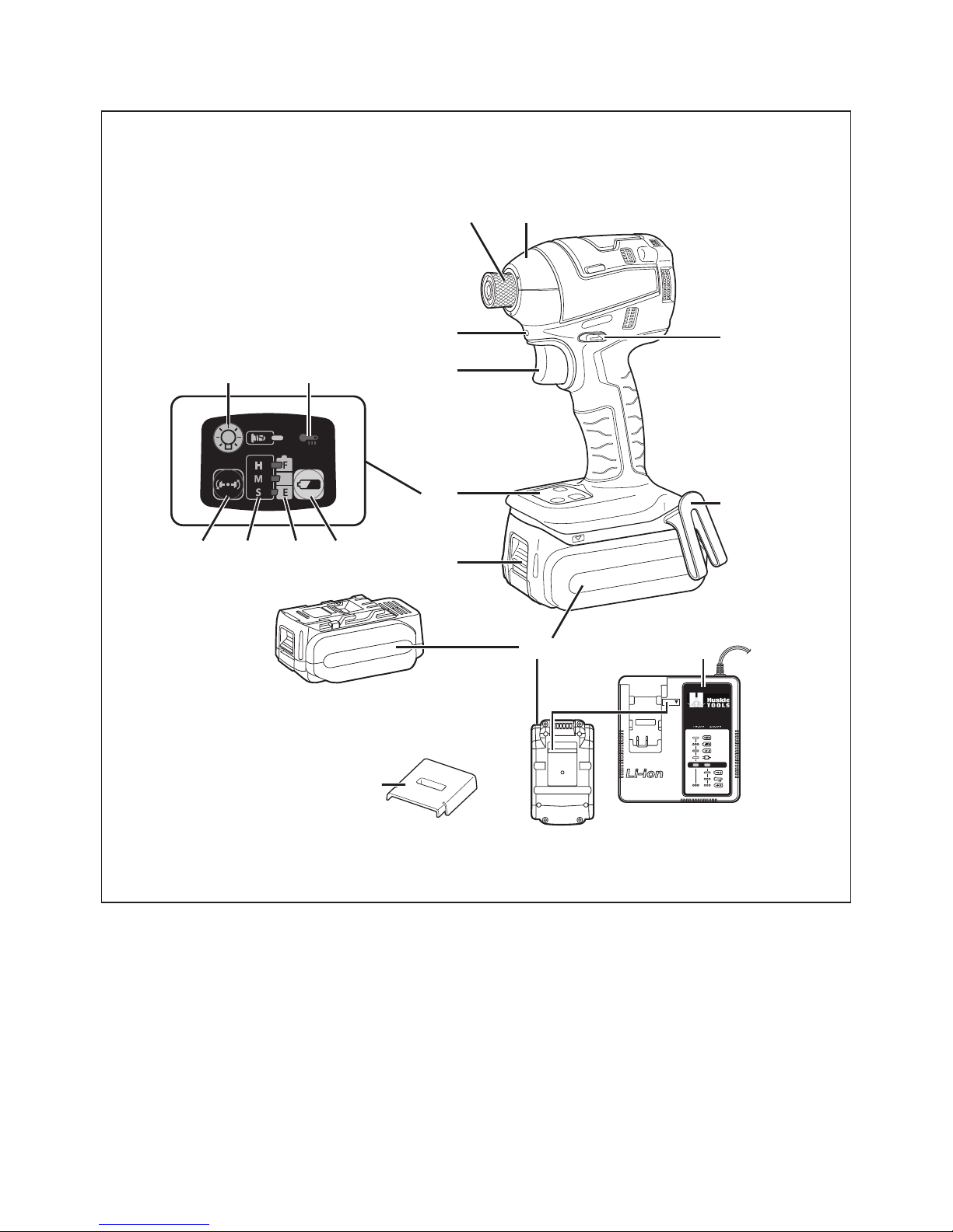
FUNCTIONAL DESCRIPTION
DESCRIPCIÓN FUNCIONAL
(B)
(O)
(N)
(A)
(C)
(D)
(E)
(F)
(Q)
(P)
(R)
(G)
(M)(L)
(K) (J) (I) (H)

(A)
6.35 mm hex quick connect chuck
Mandril hexagonal de conexión rápida
de 6,35 mm
(B)
Nose protector
Protector del morro
(C)
Forward/Reverse lever
Palanca de avance/inversión
(D)
Belt hook
Gancho del cinturón
(E)
Battery pack
Batería
(F)
Battery pack release button
Botón de liberación de batería
(G)
Control panel
Panel de controle
(H)
Battery level button
Botón de nivel de la batería
(I)
Battery level indicator
Indicador de nivel de la batería
(J)
Impact power mode display
Indicación de modo de potencia de
impacto
(K)
Impact power mode button
Botón de modo de potencia de impacto
(L)
Light button
Botón de la luz
(M)
Overheat warning lamp (motor/battery)
Luz de advertencia de sobrecalenta-
miento (motor/batería)
(N)
Variable speed control trigger
Disparador del control de velocided
variable
(O)
LED light
Luz indicadora
(P)
Battery charger
Cargador de batería
(Q)
Alignment marks
Marcas de alineación
(R)
Pack cover
Cubierta de batería
NOTE: Not all battery packs display the alignment mark (Q).
NOTA: No todas las baterías muestran la marca de alineamiento (Q).
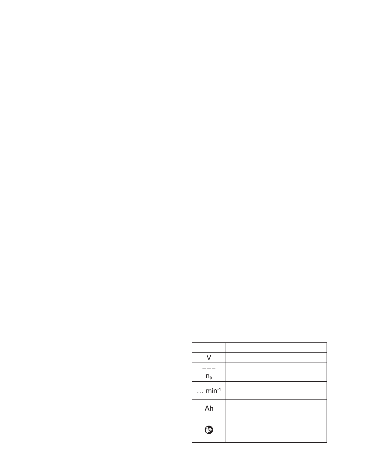
[Fig.5]
Pack cover
Cubierta de batería
Terminals
Bornes
Terminales
Label (red or yellow)
Etiqueta (roja o amarilla)
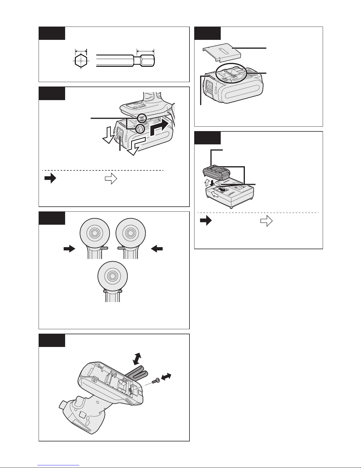
[Fig.1]
6.35 mm (1/4″) 9.5 mm (3/8″)
[Fig.2]
Attaching
Acoplamiento
Removing
Desacoplamiento
Alignment marks
Marcas de alineación
Button
Botón
[Fig.6]
Attaching
Acoplamiento
Removing
Desacoplamiento
Alignment marks
Marcas de alineación
Battery pack release button
Botón de liberación de batería
[Fig.3]
Reverse
Marcha atrás
Forward
normal
Avance
Switch lock
Bloqueo delinterruptor
[Fig.4]

This tool, as a complete unit with a battery
pack, satises appropriate IP Degrees of
Protection based on the IEC regulations.
Definition of IP code
IP5X: Ingress of dust is not totally prevented, but dust shall not penetrate in a quantity to interfere with satisfactory operation
of the tool or to impair safety (In case that
the talcum powder under 75 μm intrudes
inside the tool).
IPX6: Water projected in powerful jets
against the tool from any direction shall
have no harmful effects (In case that, with
a nozzle of 12.5 mm inner diameter,
approximately 100 L/min of normal
temperature water is injected to the tool
for 3 minutes from 3 meter distance).
LIMITED WARRANTY
The rating of IP56 qualies this tool for the
minimum impact of water or dust, but not
for the assurance of performance in such
conditions. See Safety and Operating
Instructions for further details for proper
operation.
I. General Power Tool Safety
Warnings
WARNING! Read all safety
warnings and all instructions. Failure
to follow the warnings and instructions
may result in electric shock, fire and/or
serious injury.
Save all warnings and instructions for
future reference.The term ²power tool²
in the warnings refers to your mainsoperated (corded) power tool or
battery-operated (cordless) power tool.
Work Area Safety
1)
Keep work area clean and well lit.
Cluttered or dark areas invite
accidents.
2)
Do not operate power tools in
explosive atmospheres, such as in
the presence of flammable liquids,
Power tools create sparks which may
ignite the dust or fumes.
3) Keep children and bystanders away
while operating a power tool.
Distractions can cause you to lose
control.
Electrical Safety
1) Power tool plugs must match the
outlet. Never modify the plug in any
way. Do not use any adapter plugs
with earthed (grounded) power
tools.
Unmodied plugs and matching
outlets will reduce risk of electric
shock.
2)
Avoid body contact with earthed or
grounded surfaces such as pipes,
radiators, ranges and refrigerators.
There is an increased risk of electric
shock if your body is earthed or
grounded.
3) Do not expose power tools to rain
or wet conditions.
Water entering a power tool will
increase the risk of electric shock.
4)
Do not abuse the cord. Never use
the cord for carrying, pulling or
unplugging the power tool. Keep
cord away from heat, oil, sharp
edges or moving parts.
Damaged or entangled cords increase
the risk of electric shock.
5) When operating a power tool
outdoors, use an extension cord
suitable for outdoor use.
Use of a cord suitable for outdoor use
reduces the risk of electric shock.
6) If operating a power tool in a damp
location is unavoidable, use a
residual current device (RCD)
protected supply.
Use of RCD reduces the risk of electrical shock.

Personal Safety
1) Stay alert, watch what you are
doing and use common sense
when operating a power tool. Do
not use a power tool while you are
tired or under the inuence of
drugs, alcohol or medication.
A moment of inattention while operat-
ing power tools may result in personal
injury.
2)
Use personal protective equipment.
Always wear eye protection.
Protective equipment such as dust
mask, non-skid safety shoes, hard hat,
or hearing protection
used for appropriate conditions will
reduce personal injuries.
3)
Prevent unintentional starting.
A moment of inattention while
operating power tools may result in
serious personal injury.
4)
Remove any adjusting key or
wrench before turning the power
tool on.
A wrench or a key left attached to a
rotating part of the power tool may
result in personal
injury.
5)
Do not overreach. Keep proper
footing and balance at all times.
This enables better control of the
power tool in unexpected situations.
6) Dress properly. Do not wear loose
clothing or jewelry. Keep your hair,
clothing and gloves away from
moving parts.
Loose clothes, jewelry or long hair can
be caught in moving parts.
7)
If devices are provided for the
connection of dust extraction and
collection facilities, ensure these
are connected and properly used.
Use of dust collection can reduce
dust-related hazards.
Power Tool Use and Care
1) Do not force the power tool. Use
the correct power tool for your
application.
The correct power tool will do the job
better and safer at the rate for which it
was designed.
2) Do not use the power tool if the
switch does not turn it on and off.
Any power tool that cannot be
controlled with the switch is dangerous and must be repaired.
3)
Disconnect the plug from the
power source and/or the battery
pack from the power tool before
making any adjustments, changing
accessories, or storing power
tools.
Such preventive safety measures
reduce the risk of starting the power
tool accidentally.
4)
Store idle power tools out of the
reach of children and do not allow
persons unfamiliar with the power
tool or these instructions to
operate the power tool.
Power tools are dangerous in the
hands of untrained users.
5)
Maintain power tools. Check for
misalignment or binding of moving
parts, breakage of parts and any
other condition that may affect the
power tools operation. If damaged,
have the power tool repaired before
use.
Many accidents are caused by poorly
maintained power tools.
6)
Keep cutting tools sharp and clean.
Properly maintained cutting tools with
sharp cutting edges are less likely to
bind and are easier to control.
7)
Use the power tool, accessories
and tool bits etc. in accordance
with these instructions, taking into
account the working conditions
and the work to be performed.
Use of the power tool for operations
different from those intended could
result in a hazardous situation.
Battery Tool Use and Care
1) Ensure the switch is in the off
position before inserting battery
pack.
Inserting battery pack into power tools
that have the switch on invites acci-
dents.
2) Recharge only with the charger
specied by the manufacturer.
A charger that is suitable for one type
of battery pack may create a risk of
re when used with another battery
pack.
3) Use power tools only with speci-
cally designated battery packs.
Use of any other battery packs may
create a risk of injury and re.
4) When battery pack is not in use,
keep it away from other metal
objects like paper clips, coins,
keys, nails, screws, or other small
metal objects that can make a
connection from one terminal to
another.
Shorting the battery terminals together
may cause burns, or a re.
5) Under abusive conditions, liquid
may be ejected from battery; avoid
contact. If contact accidentally
occurs, ush with water. If liquid
contacts eyes, additionally seek
medical help.
Liquid ejected from the battery may
cause irritation or burns.
Service
1)
Have your power tool serviced by
a qualified repair person using
only identical replacement
parts.This will ensure that the safety
of the power tool is maintained.
II. SPECIFIC SAFETY
RULES
1) Wear ear protection. Exposure to
noise can cause hearing loss.
2) Be aware that this tool is always in an
operating condition, since it does not
have to be plugged into an electrical
outlet.
3) Hold power tools by insulated gripping
surfaces when performing an operation where the cutting tool may
contact hidden wiring.
Contact with a “live” wire will make
exposed metal parts of the tool “live”
and shock the operator.
4) If the bit becomes jammed, immedi-
ately turn the trigger switch off to
prevent an overload which can
damage the battery pack or motor.
Use reverse motion to loosen jammed
bits.
5) Do NOT operate the Forward/Reverse
lever when the trigger switch is on.
The battery will discharge rapidly and
damage to the unit may occur.
6) When storing or carrying the tool, set
the Forward/Reverse lever to the
center position (switch lock).
7) Do not strain the tool by holding the
speed control trigger halfway (speed
control mode) so that the motor stops.
The protection circuit will activate and
may prevent speed control operation.
If this happens, release the speed
control trigger and squeeze again for
normal operation.
8) Be careful not to get dust inside the
chuck.
9) Do not touch the rotating parts to
avoid injury.
10) Do not use the tool continuously for a
long period of time. Stop using the
tool from time to time to avoid
temperature rise and heat overload of
the motor.
11) Do not drop the tool.
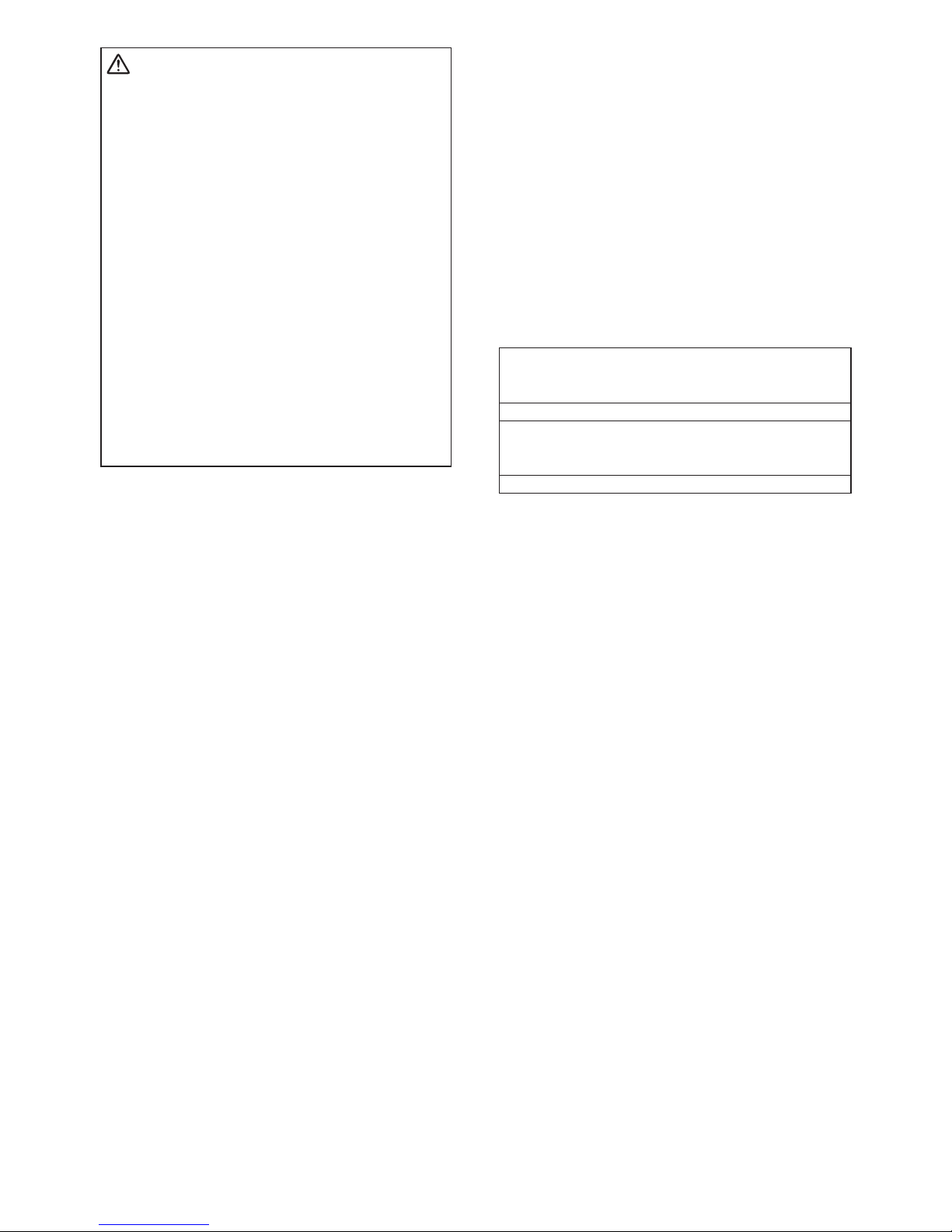
Symbol Meaning
Volts
Direct current
No load speed
Revolutions or reciprocations
per minutes
Electrical capacity of battery
pack
To reduce the risk of injury
user must read and under-
stand instruction manual.
WARNING:
Some dust created by power sanding,
sawing, grinding, drilling, and other
construction activities contains chemi-
cals known to the State of California to
cause cancer, birth defects or other
reproductive harm. Some examples of
these chemicals are:
• Lead from lead-based paints
• Crystalline silica from bricks and
cement and other masonry products
• Arsenic and chromium from chemically-treated lumber.
To reduce your exposure to these chemi-
cals: work in a well ventilated area, and
work with approved safety equipment,
such as dust masks that are specially
designed to lter out microscopic particles.
III. FOR BATTERY
CHARGER &
BATTERY PACK
Important Safety Instructions
1) SAVE THESE INSTRUCTIONS—This
manual contains important safety and
operating instructions for battery
charger.
2) Before using battery charger, read all
instructions and cautionary markings
on battery charger, battery pack, and
product using battery pack.
3) CAUTION—To reduce the risk of
injury, charge only Huskie Tools
Battery Pack as shown in last page.
Other types of batteries may burst
causing personal injury and damage.
4) Do not expose charger and battery
pack to rain or snow.
5) To reduce risk of damaging the electric plug and cord, pull by plug rather
than cord when disconnecting charger.
6) Make sure cord is located so that it
will not be stepped on, tripped over, or
otherwise subjected to damage or
stress.
7) An extension cord should not be used
unless absolutely necessary.
Use of improper extension cord could
result in a risk of re and electric
shock. If extension cord must be
used, make sure that:
a. pins on plug of extension cord are
the same number, size and shape
as those of plug on charger.
b. extension cord is properly wired
and in good electrical condition.
c. wire size is large enough for
ampere rating of charger as specied below.
RECOMMENDED MINIMUM AWG SIZE OF
EXTENSION CORDS FOR BATTERY CHAR-
GERS
AC Input Rating. Amperes AWG Size of Cord
Equal to or
greater than
But less
than
Length of Cord,
Feet
25 50 100 150
0 2 18 18 18 16
8) Do not operate charger with damaged
cord or plug—replace them immedi-
ately.
9) Do not operate charger if it has
received a sharp blow, been dropped,
or otherwise damaged in any way;
take it to a qualied service personnel.
10) Do not disassemble charger; take it to
a qualied service personnel when
service or repair is required. Incorrect
reassembly may result in a risk of
electric shock or re.
11) To reduce the risk of electric shock,
unplug charger from outlet before
attempting any maintenance or cleaning.
12) The charger and battery pack are
specically designed to work together.
Do not attempt to charge any other
cordless tool or battery pack with this
charger.
13) Do not attempt to charge the battery
pack with any other charger.
14) Do not attempt to disassemble the
battery pack housing.

15) Do not store the tool and battery pack
in locations where the temperature
may reach or exceed 50°C (122°F)
(such as a metal tool shed, or a car in
the summer), which can lead to
deterioration of the storage battery.
16) Do not charge battery pack when the
temperature is BELOW 0°C (32°F) or
ABOVE 40°C (104°F). This is very
important in order to maintain optimal
condition of the battery pack.
17) Do not incinerate the battery pack. It
can explode in a re.
18) Avoid dangerous environment. Do not
use charger in damp or wet locations.
19) The charger is designed to operate on
standard household electrical power
only. Do not attempt to use it on any
other voltage!
20) Do not abuse cord. Never carry
charger by cord or yank it to discon-
nect from outlet. Keep cord away from
heat, oil and sharp edges.
21) Charge the battery pack in a well
ventilated place, do not cover the
charger and battery pack with a cloth,
etc., while charging.
22) Use of an attachment not recommended may result in a risk of re,
electric shock, or personal injury.
23) Do not short the battery pack. A
battery short can cause a large
current ow, over heating and create
the risk of re or personal injury.
24) NOTE: If the supply cord of this
appliance is damaged, it must only be
replaced by a repair shop authorized
by the manufacturer, because special
purpose tools are required.
25) TO REDUCE THE RISK OF ELECTRIC SHOCK, THIS APPLIANCE
HAS A POLARIZED PLUG (ONE
BLADE IS WIDER THAN THE
OTHER).
This plug will t in a polarized outlet
only one way. If the plug does not t
fully in the outlet, reverse the plug. If it
still does not t, contact a qualied
electrician to install the proper outlet.
Do not change the plug in any way.
WARNING:
• Do not use other than the Huskie Tools
battery packs that are designed for use
with this rechargeable tool.
• Huskie Tools is not responsible for any
damage or accident caused by the use
of recycled or counterfeit battery pack.
• Do not dispose of the battery pack in a
re, or expose it to excessive heat.
• Do not allow metal objects to touch the
battery pack terminals.
• Do not carry or store the battery pack in
the same container as nails or similar
metal objects.
• Do not charge the battery pack in a
high-temperature location, such as next
to a re or in direct sunlight. Otherwise,
the battery may overheat, catch re, or
explode.
• After removing the battery pack from
the tool or the charger, always reattach
the pack cover. Otherwise, the battery
contacts could be shorted, leading to a
risk of re.
• When the Battery Pack Has Deteriorated, Replace It with a New One. Contin-
ued use of a damaged battery pack
may result in heat generation, ignition
or battery rupture.
• To prevent leakage, overheating,
smoke generation, re, and rupturing
from occurring, follow these instructions
when handling our rechargeable power
tools (tool main body/battery pack/
charger).
- Do not allow material cuttings or dust
to fall onto the battery pack.
- When storing, remove any material
cuttings and dust from the battery
pack, and place the battery pack
separately from metal objects
(screws, nails, etc.) when storing in
the tool case.
• Do not handle the rechargeable power
tools in the following way.
(There is a hazard of smoke generation, re, and rupturing)
- Use or leave in places exposed to
rain or moisture
- Use submerging in water

IV. ASSEMBLY
Attaching or Removing Bit
NOTE:
When attaching or removing a bit,
disconnect battery pack from tool or
place the switch in the center position
(switch lock).
1. Hold the collar of quick connect chuck
and pull it out from the driver.
2. Insert the bit into the chuck. Release
the collar.
3. The collar will return to its original
position when it is released.
4. Pull the bit to make sure it does not
come out.
5. To remove the bit, pull out the collar in
the same way.
CAUTION:
If the collar does not return to its
original position or the bit comes out
when pulled on, the bit has not been
properly attached. Make sure the bit is
properly attached before use.
Use 6.35 mm hexagonal bits.
To ensure proper securement of the bit,
use only hexagonal bits with 9.5 mm
detent. [Fig.1]
Attaching or Removing Battery
Pack
1. To attach the battery pack: [Fig.2 ]
Align the highlighted marker points and
attach battery pack.
Slide the battery pack until it locks into
position.
2. To remove the battery pack: [Fig.2 ]
Push the button and slide the battery
pack forward.
V. OPERATION
WARNING!
• Do not inhale any smoke emitted from
the tool or battery pack as it may be
harmful.
[Main Body]
CAUTION
• When storing or carrying the tool, set
the Forward/Reverse lever to the
center position (switch lock).
NOTE:
Exercise caution to ensure no objects
come into contact with the tool’s
trigger switch.
If an object comes into contact with
the tool’s trigger switch, even while
the Forward/Reverse lever is in the
center position (locked), a small
amount of electric current may
continue owing, which may cause an
excessive discharge from the battery
pack and subsequent battery pack
failure.
Switch and Forward/Reverse Lever
Operation [Fig.3]
1. Push the lever for forward or reverse
rotation. Check the direction of the
lever before using.
2. Depress the trigger switch slightly to
start the tool slowly.
3. Speed will increase by pressing the
trigger. The tool stops working immediately by releasing the trigger.
4. When done with an application, lock the
switch by centering the lever.
NOTE:
The more the speed control trigger is
pulled, the higher the speed becomes.
CAUTION:
When operating the tool by pulling the
trigger, there may be a momentary lag
before rotation starts. This does not
signal a malfunction.
* This lag occurs as the tool’s circuitry
starts up when the trigger is pulled for
the rst time after installing a battery
pack or after the tool has not been
used for at least 1 minute (or at least
5 minutes when the LED is on).
Rotation will start without any lag
during second and subsequent opera-
tions.
Changing the Belt Hook Location
Side [Fig.4]
The belt hook can be attached to either
side of the unit.
1. Removing the hook
(1) Remove the nut.
(2) Draw out the hook.
2. Attaching the hook to the other side
(1) Insert the hook in the other side.
(2) Tighten the nut fully so that it
securely fastened.
Impact Power Mode Select
• Selecting the impact power among 4
modes (Hard, Self-drilling screw, Soft,
Medium).
Press the impact power mode button to
set it. The mode changes to Hard,
Self-drilling screw, Soft or Medium each
time the button is pressed.
The driver is preset to “Hard” impact
mode setting when shipped from the
manufacturer.
Soft
0 – 950 rpm
and
0 – 1900 i.p.m.
• Jobs requiring limited
torque with eliminating
the possibility of break-
ing screw, chipping
screw head, or break-
ing bit.
• Jobs requiring minimal
damage of nished
exterior surface.
* Fastening smaller
diameter bolt (M6 or
smaller)
* Fastening into
plastic
* Installing drywall
Self-drilling
screw
0 – 2500 rpm
and
0 – 1200 i.p.m.
• Jobs requiring ush
nish of self-drilling
screw.
(dia. 4 mm × 15 mm or
smaller)
(Automatic mode
change starting from
Hard mode to slower
rpm before ush nish)
* i.p.m. = Impact per minute.
Avoid repeatedly depressing the switch
when the bolts and screws are securely
fastened.
Not doing so may cause a delay in rotation
starting, or the Impact Power mode
display to ash and prevent rotation from
starting for circuit protection.
Hard
0 – 2500 rpm
and
0 – 3100 i.p.m.
• Jobs requiring high
torque where there is
no possibility of breaking screw or chipping
screw head.
* Fastening larger
size bolt (M8 or
larger)
* Fastening long
wood screw
Medium
0 – 1450 rpm
and
0 – 2900 i.p.m.
• Jobs requiring decent
torque with minimizing
the possibility of breaking screw, chipping
screw head, or breaking bit.
* Fastening smaller
diameter bolt (such
as M6)

LED Light
Press the light button and set illumination
condition.
Illuminated
Illuminates by pressing button.
The light turns off when the tool
has not been used for more
than 5 minutes or just after
attaching the battery pack.
Depress the trigger switch and
operate the tool once.
Interlocking trigger
Illuminates when depressing the
trigger switch.
Turns off when the trigger is
released.
Off
The light illuminates with very low current,
and it does not adversely affect the perfor-
mance or its battery capacity.
CAUTION:
• The built-in LED light is designed to
illuminate the small work area temporarily.
• Do not use it as a substitute for a
regular ashlight, since it does not
have enough brightness.
CAUTION: DO NOT STARE INTO
BEAM.
Use of controls or adjustments or performance of procedures other than those
specied herein may result in hazardous
radiation exposure.
Overheat warning
Off
(normal
operation)
Illuminated:
Overheat
(motor)
Flashing:
Overheat
(battery)
Indicates operation has been halted due to
motor or battery overheating.
To protect the motor or battery, be sure to
note the following when carrying out this
operation.
• If the motor or battery becomes hot, the
protection function will be activated and
the motor or battery will stop operating.
The overheat warning lamp on the
control panel illuminates or ashes when
this feature is active.
• If the overheating protection feature
activates, allow the tool to cool thoroughly (at least 30 minutes). The tool is ready
for use when the overheat warning lamp
goes out.
• Avoid using the tool in a way that causes
the overheating protection feature to
activate repeatedly.
• If the tool is operated continuously under
high-load conditions or if it is used in
hot-temperature conditions (such as
during summer), the overheating protection feature may activate frequently.
• If the tool is used in cold-temperature
conditions (such as during winter) or if it
is frequently stopped during use, the
overheating protection feature may not
activate.
The performance of the EY9L42 deteriorates signicantly at and below 10°C due
to work conditions and other factors.
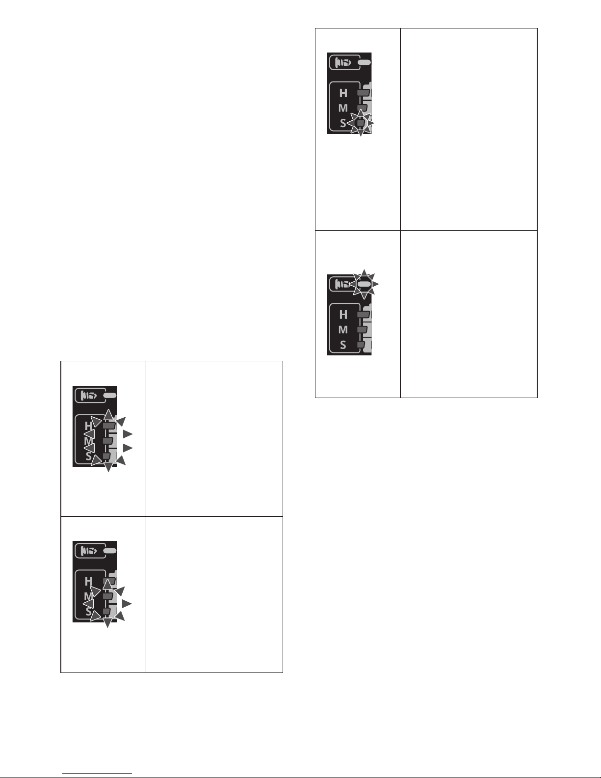
Battery Level Indicator
Press the battery level button.
Battery level indicator shows battery level
in three levels while pressing the button.
It shifts to Impact power mode when
release the button.

NOTE:
The indicator will not show the battery
level even the button is pressed in the
following cases.
• The main unit is powered off.
• Just after attaching the battery pack
• The main unit or battery level button is
not operated for approx. ve minutes.
Press the battery level button again
after depressing the trigger switch.
• If the battery temperature is high, stop
the operation and wait until the battery
temperature is low.
Indicator Battery status
3 lamps
illuminated
Charged
enough
2 lamps
illuminated
Approx. 60%
remaining
One lamp
illuminated
Battery level is
low.
Need to be
charged soon
3 lamps
ashing
Empty
Need to be
charged immediately
Battery level indication is just guide.
The indication may change due to the
condition of battery or ambient temperature.
Excessive (complete) discharging of
lithium ion batteries shortens their service
life dramatically. The driver includes a
battery protection feature designed to
prevent excessive discharging of the
battery pack.
[Battery Pack]
For Appropriate Use of
Battery Pack [Fig.5]
• The rechargeable batteries have a
limited life.
• For optimum battery life, store the Li-ion
battery pack following use without
charging it.
• When operating the battery pack, make
sure the work place is well ventilated.
For safe use
• The battery pack is designed to be
installed by proceeding two steps for
safety. Make sure the battery pack is
installed properly to the main unit before
use.
• If the battery pack is not connected rmly
when the switch is switched on, the
overheat warning lamp and the battery
low warning lamp will ash to indicate
that safe operation is not possible, and
the main unit will not rotate normally.
Connect the battery pack into the unit of
the tool until the red or yellow label
disappears.
Battery Recycling
ATTENTION:
A Li-ion battery that is recyclable
powers the product you have
purchased. Please call
1-800-8-BATTERY for information on
how to recycle this battery.
[Battery Charger]
Charging
CAUTION:
1) If the temperature of the battery pack
falls approximately below −10°C
(14°F), charging will automatically
stop to prevent degradation of the
battery.

2) The ambient temperature range is
between 0°C (32°F) and 40°C
(104°F).
If the battery pack is used when the
battery temperature is below 0°C
(32°F), the tool may fail to function
properly.
3) Use the charger at temperatures
between 0°C and 40°C, and charge
the battery at a temperature similar to
that of the battery itself. (There should
be no more than a 15°C difference
between the temperatures of the
battery and the charging location.)
4) When charging a cool battery pack
(below 0°C (32°F)) in a warm place,
leave the battery pack at the place
and wait for more than one hour to
warm up the battery to the level of the
ambient temperature.
5) Cool down the charger when charging
more than two battery packs consecu-
tively.
6) Do not insert your ngers into contact
hole, when holding charger or any
other occasions.
7) To prevent the risk of re or damage
to the battery charger.
• Do not cover vent holes on the char-
ger and the battery pack.
• Unplug the charger when not in use.
NOTE:
Your battery pack is not fully charged at
the time of purchase. Be sure to charge
the battery before use.
How to charge
1. Plug the charger into the AC outlet.
NOTE:
Sparks may be produced when the plug
is inserted into the AC power supply,
but this is not a problem in terms of
safety.
2. Connect the battery pack rmly into the
charger.
1 Line up the alignment marks and
place the battery onto the dock on
the charger.
NOTE:
Not all battery packs display the
alignment mark (Q) (on page 2).
2 Slide forward in the direction of the
arrow. [Fig.6 ]
3. During charging, the charging lamp will
be lit. When charging is completed, an
internal electronic switch will automati-
cally be triggered to prevent overcharging.
• Charging will not start if the battery
pack is hot (for example, immediately
after heavy-duty operation).
The orange standby lamp will be
ashing until the battery cools down.
Charging will then begin automatically.
4. The charge lamp (green) will ash
slowly once the battery is approximate-
ly 80% charged.
5. When charging is completed, the
charging lamp in green color will turn
off.
6. If the temperature of the battery pack is
0°C or less, charging takes longer to
fully charge the battery pack than the
standard charging time.
Even when the battery is fully charged,
it will have approximately 50% of the
power of a fully charged battery at
normal operating temperature.
7. Consult an authorized dealer if the
charging lamp (green) does not turn off.
8. If a fully charged battery pack is inserted into the charger again, the charging
lamp lights up. After several minutes,
the charging lamp in green color will
turn off.
9. Remove the battery pack while the
battery pack release button is held up.
[Fig.6
]
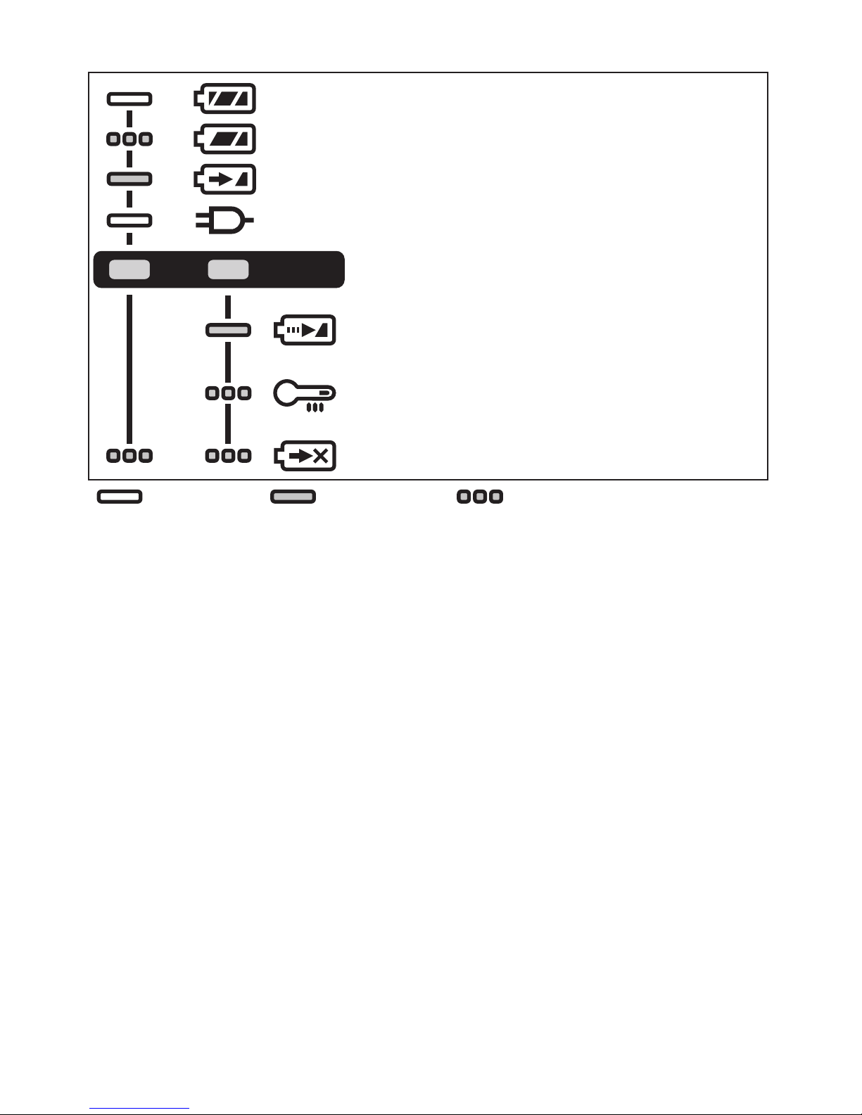
LAMP INDICATIONS
Charging is completed. (Full charge.)
Battery is approximately 80% charged.
Now charging.
Turn off Illuminated
Flashing
Charger is plugged into the AC outlet. Ready to charge.
Charging Status Lamp.
Left: green Right: orange will be displayed.
Battery pack is cool.
The battery pack is being charged slowly to reduce the load on
the battery.
Battery pack is warm.
Charging will begin when temperature of battery pack drops. If
the temperature of the battery pack is -10° or less, the charging
status lamp (orange) will also start ashing. Charging will begin
when the temperature of the battery pack goes up.
Charging is not possible. Clogged with dust or malfunction of
the battery pack.
(Green) (Orange)
VI. MAINTENANCE
• Use only a dry, soft cloth for wiping the unit.
Do not use a damp cloth, thinner, benzine, or other volatile solvents for cleaning.
• In the event that the inside of the tool or battery pack is exposed to water, drain and allow
to dry as soon as possible. Carefully remove any dust or iron lings that collect inside the
tool. If you experience any problems operating the tool, consult with a repair shop.
VII. ACCESSORIES
Use only suitable size of bit.

VIII. APPENDIX
MAXIMUM RECOMMENDED CAPACITIES
Model No. HTP-CID
Screw
driving
Wood screw Φ 3.5 mm – Φ 9.5 mm (1/8″ – 3/8″)
Self-drilling screw Φ 3.5 mm – Φ 6 mm (1/8″ – 1/4″)
Bolt fastening
Standard bolt : M6 – M16 (1/4″ – 5/8″)
High tensile bolt : M6 – M12 (1/4″ – 15/32″)
WARRANTY SUPPLEMENT
• The breakdown and damage caused by usage consistent for a long time (e.g.: factory
work on the assembly line, etc.) is out of warranty.
• In the event that the inside of the tool or battery pack is exposed to water, drain and allow
to dry as soon as possible. Carefully remove any dust or iron lings that collect inside the
tool. If you experience any problems operating the tool, consult with a repair shop.
IX. SPECIFICATIONS
NOTE: Weight indication
Greater than or equal to 1 kg: indicated by 0.05 kg (0.11 lbs).
Less than 1 kg: indicated by 0.01 kg (0.02 lbs).
MAIN UNIT
Model No. HTP-CID
Motor voltage 18 V DC
No load
speed
Soft mode
0 min-1 (rpm) – 950 min-1 (rpm)
Medium mode
0 min-1 (rpm) – 1450 min-1 (rpm)
Hard mode
0 min-1 (rpm) – 2500 min-1 (rpm)
Self-drilling screw
mode
0 min-1 (rpm) – 2500 min-1 (rpm)
Maximum torque 160 N•m (1416 in-lbs)
Impact per
minute
Soft mode
0 min-1 (ipm) – 1900 min-1 (ipm)
Medium mode
0 min-1 (ipm) – 2900 min-1 (ipm)
Hard mode
0 min-1 (ipm) – 3100 min-1 (ipm)
Self-drilling screw
mode
0 min-1 (ipm) – 1200 min-1 (ipm)
Overall length 118 mm (4-21/32″)
Weight
With battery pack:
BP-185
1.65 kg (3.64 lbs)

BATTERY PACK
Model No.
BP-185
Storage battery
Li-ion battery
Battery voltage
18 V DC
(3.6 V × 10 cells)
NOTE : This chart may include models that are not available in your area.
Please refer to the latest general catalogue.
BATTERY CHARGER
Model No.
CH-185
Electrical rating
See the rating plate on the bottom of charger
Weight
0.93 kg (2 lbs)
Full Charging time
Model No.
BP-185
80 min.
Federal Communication Commission Interference Statement
This equipment has been tested and found to comply with the limits for a Class B digital
device, pursuant to Part 15 of the FCC Rules. These limits are designed to provide reasonable protection against harmful interference in a residential installation. This equipment
generates, uses and can radiate radio frequency energy and, if not installed and used in
accordance with the instructions, may cause harmful interference to radio communications.
However, there is no guarantee that interference will not occur in a particular installation. If
this equipment does cause harmful interference to radio or television reception, which can
be determined by turning the equipment off and on, the user is encouraged to try to correct
the interference by one of the following measures:
• Reorient or relocate the receiving antenna.
• Increase the separation between the equipment and receiver.
• Connect the equipment into an outlet on a circuit different from that to which the receiver
is connected.
• Consult the dealer or an experienced radio/TV technician for help.
FCC Caution: To assure continued compliance, install and use in accordance with provided
instructions. Use only the battery pack specied in the instructions. Any changes or modications not expressly approved by the party responsible for compliance could void the
user’s authority to operate this equipment.
This device complies with part 15 of the FCC Rules. Operation is subject to the following
two conditions: (1) This device may not cause harmful interference, and (2) this device
must accept any interference received, including interference that may cause undesired
operation.
This Class B digital apparatus complies with Canadian ICES-003.
X. HARMONIZED STANDARDS
MAIN UNIT
Conforms to UL Std. 60745-1 & 60745-2-2
Certied to CSA Std.C22.2 No. 60745-1 & 60745-2-2
BATTERY CHARGER
Conforms to UL Std.1310
Certified to CSA Std.C22.2 No. 223-M91

195 Internationale Blvd
Glendale Heights, IL 60139
Phone 800-860-6170
Fax 800-345-3767
www.huskietools.com
 Loading...