


Cordless Angle Grinder
Amoladora angular inalámbrica
Operating Instructions
Manual de instrucciones
Model No: HTP-AGR
IMPORTANT
This manual contains safety information. Read manual completely before rst using this product and save this
manual for future use.
IMPORTANTE
Este manual contiene información de seguridad. Lea completamente este manual antes de utilizar por primera
vez este producto, y guárdelo para poder consultarlo en el futuro.

Index/Index/Indice
English: Page 6
Español: Página
23
FUNCTIONAL DESCRIPTION
DESCRIPCIÓN FUNCIONAL
(O)
10.8 V ─ 28.8 V
(Q)
(Q)
(D)
(P)
(R)
(S)
(T)
(Q)
(E) (F)
(C)
(G)
(I)
(A)
(J)
(K)
(N)
(M)
(L)
(B)
(H)

(A)
Power switch
Interruptor de alimentación
(B)
Brush cap
Tapa de cepillo
(C)
Display panel
Panel de exhibición
(D)
Battery low warning lamp
Luz de aviso de baja carga de batería
(E)
On lock warning lamp
Luz de advertencia de bloqueo
(F)
Overheat warning lamp (battery)
Luz de advertencia de sobrecalentamiento
(batería)
(G)
Battery pack release button
Botón de liberación de batería
(H)
Alignment mark
Marca de alineación
(I)
Battery pack
Batería
(J)
Support handle
Mango de soporte
(K)
Support handle mounting hole
Oricio de montaje de mango de soporte
(L)
Grinding disc guard
Protección de disco de desbastado
(M)
Grinding disc guard xing screw
Tornillo de jación de protector de disco de
amoladora
(N)
Spindle
Eje
(O)
Spindle lock button
Botón de bloqueo de eje
(P)
Battery charger
Cargador de batería
(Q)
Battery pack cover
Cubierta de la batería
(R)
Clamp nut
Tuerca de abrazadera
(S)
Disc ange
Brida de disco
(T)
Disc wrench
Llave de disco
[Fig.6]
[Fig.2]
[Fig.3]
[Fig.4]
[Fig.5]
[Fig.7]
[Fig.9]
[Fig.8]
[Fig.1]
1. Grinding disc guard
Protección de disco de desbastado
2. Spindle
Eje
3. Grinding disc guard fixing screw
Tornillo de fijación de protector de disco de
amoladora
Spindle lock button
Botón de bloqueo de eje
Alignment marks
Marcas de alineación
Button
Botón
1
2
3
1. Clamp nut
Tuerca de abrazadera
2. Grinding disc
Disco de desbastado
3. Disc flange
Brida de disco
1
2
3
Make sure the side.
Assurez-vous du côté.
Asegure el costado.
[Fig.10]
B
A
Carbon brush
Cepillo de carbón
Screw driver
Destornillador
Brush cap
Tapa de cepillo
[Fig.19]
[Fig.11] [Fig.12]
[Fig.14]
[Fig.16] [Fig.17]
[Fig.18]
[Fig.15]
[Fig.13]
1. Clamp nut
Tuerca de abrazadera
2. Cut-off disc
Disco de corte
3. Disc flange
Brida de disco
4. Spindle
Eje
ON→OFF
ON→OFF
OFF→ON
OFF→ON
Off (normal operation)
Apagado (funcionamiento normal)
Flashing (No charge) Battery protection feature active
Destella (Sin carga) Se activó la function de protección de la batería
Off (normal operation)
Apagado (funcionamiento normal)
Flashing: Overheat
Destella: Sobrecalentamiento
Make sure the side.
Asegure el costado.
1
2
3
4
Alignment marks
Marcas de alineación
Battery pack release button
Botón de liberación de batería
Pack cover
cudeksel
Terminals
Terminales
Label (red or yellow)
Etiqueta (roja o amarilla)
Attaching
Acoplamiento
Removing
Desacoplamiento

How to Use This Manual
• Please read this manual completely
before starting to use your grinder. If
you let someone else use the grinder,
make sure they either read this
manual or are fully instructed in the
proper use and all safety precautions
concerning the grinder.
• Please keep this manual for future
reference. It contains important safety
information that you must follow to
use the grinder safely.
• This manual and product use the
following signal words:
NOTE:
Notes provide additional information
that you should know about the grinder.
CAUTION
Caution indicates a potentially
hazardous situation, which could
result in minor or moderate injury if
not avoided. Cautions also alert you to
unsafe practices to be avoided.
WARNING
Warning indicates a potentially
hazardous situation, which could result
in serious injury or death if not avoided.
DANGER
Danger indicates an imminent hazard
which will result in serious injury or
death if not avoided.
II. GENERAL
SAFETY RULES
WARNING! Read all instructions
Failure to follow all instructions listed
below may result in electric shock, fire
and/or serious injury. The term “power
tool” in all of the warnings listed below
refers to your main operated (corded)
power tool and battery operated
(cordless) power tool.
This tool, as a complete unit with a battery
pack, satisfies appropriate IP Degrees of
Protection based on the IEC regulations.
Definition of IP code
IP5X: Ingress of dust is not totally
prevented, but dust shall not
penetrate in a quantity to interfere with
satisfactory operation of the tool or to
impair safety (In case that the talcum
powder under 75 μm intrudes inside the
tool)
IPX6: Water projected in powerful jets
against the tool from any direction
shall have no harmful effects (In case
that, with a nozzle of 12.5 mm inner
diameter, approximately 100 L/min of
normal temperature water is injected
to the tool for 3 minutes from 3 meter
distance)
LIMITED WARRANTY
The rating of IP56 qualifies this tool
for the minimum impact of water or
dust, but not for the assurance of
performance in such conditions. See
Safety and Operating Instructions for
further details for proper operation.
I. INTRODUCTION
Thank you for purchasing the
Huskie Tools Angle Grinder. The powerful grinding action of this tool, combined
with the convenience of its rechargeable battery pack, provides you with
great grinding performance.
This Angle Grinder is only to be used
for grinding and cutting-off.
DANGER
This product is a grinding tool, designed
to grind. It has a rotating disc which
is capable of cutting you deeply,
causing serious injury or death. As a
result, please read this manual and
the cautionary markings on the tool
carefully, and obey all of the Safety
Instructions to avoid such injury.
WARNING
To reduce the risk of injury, always use
proper guards when grinding.

SAVE THESE INSTRUCTIONS
Work Area Safety
1) Keep work area clean and well lit.
Cluttered or dark areas invite
accidents.
2) Do not operate power tools in
explosive atmospheres, such as in
the presence of flammable liquids,
gases or dust.
Power tools create sparks which may
ignite the dust or fumes.
3) Keep children and bystanders
away while operating a power tool.
Distractions can cause you to lose
control.
Electrical Safety
1) Power tool plugs must match the
outlet. Never modify the plug in
any way. Do not use any adapter
plugs with earthed (grounded)
power tools.
Unmodified plugs and matching
outlets will reduce risk of electric
shock.
2) Avoid body contact with earthed or
grounded surfaces such as pipes,
radiators, ranges and refrigerators.
There is an increased risk of electric
shock if your body is earthed or
grounded.
3) Do not expose power tools to rain
or wet conditions.
Water entering a power tool will
increase the risk of electric shock.
4) Do not abuse the cord. Never use
the cord for carrying, pulling or
unplugging the power tool. Keep
cord away from heat, oil, sharp
edges or moving parts.
Damaged or entangled cords
increase the risk of electric shock.
5) When operating a power tool
outdoors, use an extension cord
suitable for outdoor use.
Use of a cord suitable for outdoor use
reduces the risk of electric shock.
Personal Safety
1) Stay alert, watch what you are
doing and use common sense
when operating a power tool. Do
not use a power tool while you
are tired or under the influence of
drugs, alcohol or medication.
A moment of inattention while
operating power tools may result in
personal injury.
2) Use safety equipment. Always
wear eye protection.
Safety equipment such as dust
mask, non-skid safety shoes, hard
hat, or hearing protection used for
appropriate conditions will reduce
personal injuries.
3) Avoid accidental starting. Ensure
the switch is in the off position
before plugging in.
Carrying power tools with your finger
on the switch or plugging in the
power tools that have the switch on
invites accidents.
4) Remove any adjusting key or
wrench before turning the power
tool on.
A wrench or a key left attached to a
rotating part of the power tool may
result in personal injury.
5) Do not overreach. Keep proper
footing and balance at all times.
This enables better control of the
power tool in unexpected situations.
6) Dress properly. Do not wear loose
clothing or jewelry. Keep your hair,
clothing and gloves away from
moving parts.
Loose clothes, jewelry or long hair
can be caught in moving parts.
7) If devices are provided for the
connection of dust extraction and
collection facilities, ensure these
are connected and properly used.
Use of these devices can reduce dust
related hazards.

Power Tool Use and Care
1) Do not force the power tool. Use
the correct power tool for your
application.
The correct power tool will do the job
better and safer at the rate for which
it was designed.
2) Do not use the power tool if the
switch does not turn it on and off.
Any power tool that cannot be
controlled with the switch is
dangerous and must be repaired.
3) Disconnect the plug from the
power source and/or the battery
pack from the power tool before
making any adjustments, changing
accessories, or storing power
tools.
Such preventive safety measures
reduce the risk of starting the power
tool accidentally.
4) Store idle power tools out of
the reach of children and do not
allow persons unfamiliar with the
power tool or these instructions to
operate the power tool.
Power tools are dangerous in the
hands of untrained users.
5) Maintain power tools. Check for
misalignment or binding of moving
parts, breakage of parts and any
other condition that may affect the
power tools operation. If damaged,
have the power tool repaired
before use.
Many accidents are caused by poorly
maintained power tools.
6) Keep cutting tools sharp and
clean.
Properly maintained cutting tools with
sharp cutting edges are less likely to
bind and are easier to control.
7) Use the power tool, accessories
and tool bits etc. in accordance
with these instructions and in the
manner intended for the particular
type of power tool, taking into
account the working conditions
and the work to be performed.
Use of the power tool for operations
different from those intended could
result in a hazardous situation.
Battery Tool Use and Care
1) Ensure the switch is in the off
position before inserting battery
pack.
Inserting battery pack into power
tools that have the switch on invites
accidents.
2) Recharge only with the charger
specified by the manufacturer.
A charger that is suitable for one type
of battery pack may create a risk of
fire when used with another battery
pack.
3) Use power tools only with
specifically designated battery
packs.
Use of any other battery packs may
create a risk of injury and fire.
4) When battery pack is not in use,
keep it away from other metal
objects like paper clips, coins,
keys, nails, screws, or other small
metal objects that can make a
connection from one terminal to
another.
Shorting the battery terminals
together may cause burns, or a fire.
5) Under abusive conditions, liquid
may be ejected from battery; avoid
contact. If contact accidentally
occurs, flush with water. If liquid
contacts eyes, additionally seek
medical help.
Liquid ejected from the battery may
cause irritation or burns.
Service
1) Have your power tool serviced by
a qualified repair person using
only identical replacement parts.
This will ensure that the safety of
power tool is maintained.

7) Do not use a damaged accessory.
Before each use inspect the
accessory such as abrasive
wheels for chips and cracks.
If power tool or accessory is
dropped, inspect for damage or
install an undamaged accessory.
After inspecting and installing an
accessory, position yourself and
bystanders away from the plane of
the rotating accessory and run the
power tool at maximum no-load
speed for one minute. Damaged
accessories will normally break apart
during this test time.
8) Wear personal protective
equipment. Depending on
application, use face shield,
safety goggles or safety glasses.
As appropriate, wear dust mask,
hearing protectors, gloves
and workshop apron capable
of stopping small abrasive or
workpiece fragments. The eye
protection must be capable of
stopping flying debris generated
by various operations. The dust
mask or respirator must be capable
of filtrating particles generated by
your operation. Prolonged exposure
to high intensity noise may cause
hearing loss.
9) Keep bystanders a safe distance
away from work area. Anyone
entering the work area must wear
personal protective equipment.
Fragments of workpiece or of a
broken accessory may fly away and
cause injury beyond immediate area
of operation.
10) Hold the power tool by insulated
gripping surfaces only, when
performing an operation where the
cutting tool may contact hidden
wiring. Contact with a “live” wire
will also make exposed metal
parts of the power tool “live” and
could give the operator an electric
shock.
11) Position the cord clear of the
spinning accessory. If you lose
control, the cord may be cut or
snagged and your hand or arm may
be pulled into the spinning accessory.
Safety instructions for all
operations
Safety warning common for Grinding
or Abrasive Cutting-off operations:
1) This power tool is intended to
function as a grinder, or cut-off
tool. Read all safety warnings,
instructions, illustrations and
specifications provided with this
power tool. Failure to follow all
instructions listed below may result in
electric shock, fire and/or serious
injury.
2) Operations such as sanding, wire
brushing, polishing are not
recommended to be performed
with this power tool. Operations
for which the power tool was not
designed may create a hazard and
cause personal injury.
3) Do not use accessories which
are not specifically designed
and recommended by the tool
manufacturer. Just because the
accessory can be attached to your
power tool, it does not assure safe
operation.
4) The rated speed of the accessory
must be at least equal to the
maximum speed marked on the
power tool. Accessories running
faster than their RATED SPEED can
break and fly apart.
5) The outside diameter and the
thickness of your accessory must
be within the capacity rating of
your power tool. Incorrectly sized
accessories cannot be adequately
guarded or controlled.
6) Threaded mounting of accessories
must match the grinder spindle
thread. For accessories mounted
by flanges, the arbour hole of the
accessory must fit the locating
diameter of the flange. Accessories
that do not match the mounting
hardware of the power tool will run
out of balance, vibrate excessively
and may cause loss of control.

12) Never lay the power tool down
until the accessory has come
to a complete stop. The spinning
accessory may grab the surface and
pull the power tool out of your control.
13) Do not run the power tool while
carrying it at your side. Accidental
contact with the spinning accessory
could snag your clothing, pulling the
accessory into your body.
14) Regularly clean the power tool’s
air vents. The motor’s fan will draw
the dust inside the housing and
excessive accumulation of powdered
metal may cause electrical hazards.
15) Do not operate the power tool near
flammable materials. Sparks could
ignite these materials.
16) Do not use accessories that
require liquid coolants. Using water
or other liquid coolants may result in
electrocution or shock.
Further safety instructions for
all operations
Kickback and Related Warnings
Kickback is a sudden reaction to a
pinched or snagged rotating wheel,
backing pad, brush or any other
accessory. Pinching or snagging
causes rapid stalling of the rotating
accessory which in turn causes
the uncontrolled power tool to be
forced in the direction opposite of the
accessory’s rotation at the point of the
binding.
For example, if an abrasive wheel is
snagged or pinched by the workpiece,
the edge of the wheel that is entering
into the pinch point can dig into the
surface of the material causing the
wheel to climb out or kick out. The
wheel may either jump toward or
away from the operator, depending on
direction of the wheel’s movement at
the point of pinching. Abrasive wheels
may also break under these conditions.
Kickback is the result of power tool
misuse and/or incorrect operating
procedures or conditions and can be
avoided by taking proper precautions
as given below.
1) Maintain a firm grip on the power
tool and position your body
and arm to allow you to resist
kickback forces. Always use
auxiliary handle, if provided, for
maximum control over kickback
or torque reaction during start-up.
The operator can control torque
reactions or kickback forces, if proper
precautions are taken.
2) Never place your hand near the
rotating accessory. Accessory may
kickback over your hand.
3) Do not position your body in the
area where power tool will move
if kickback occurs. Kickback will
propel the tool in direction opposite to
the wheel’s movement at the point of
snagging.
4) Use special care when working
corners, sharp edges etc. Avoid
bouncing and snagging the
accessory. Corners, sharp edges or
bouncing have a tendency to snag
the rotating accessory and cause
loss of control or kickback.
5) Do not attach a saw chain
woodcarving blade or toothed saw
blade. Such blades create frequent
kickback and loss of control.
Additional safety instructions
for grinding and cutting-off
operations
Safety warnings specific for Grinding
and Abrasive Cutting-off operations:
1) Use only wheel types that are
recommended for your power tool
and the specific guard designed
for the selected wheel. Wheels
for which the power tool was not
designed cannot be adequately
guarded and are unsafe.
2) The grinding surface of centre
depressed wheels must be
mounted below the plane of the
guard lip. An improperly mounted
wheel that projects through the plane
of the guard lip cannot be adequately
protected.

3) The guard must be securely
attached to the power tool and
positioned for maximum safety,
so the least amount of wheel is
exposed towards the operator.
The guard helps to protect operator
from broken wheel fragments and
accidental contact with wheel and
sparks that could ignite clothing.
4) Wheels must be used only for
recommended applications. For
example: do not grind with the
side of cut-off wheel. Abrasive
cut-off wheels are intended for
peripheral grinding, side forces
applied to these wheels may cause
them to shatter.
5) Always use undamaged wheel
flanges that are of correct size and
shape for your selected wheel.
Proper wheel flanges support the
wheel thus reducing the possibility of
wheel breakage. Flanges for cut-off
wheels may be different from grinding
wheel flanges.
6) Do not use worn down wheels
from larger power tools. Wheel
intended for larger power tool is not
suitable for the higher speed of a
smaller tool and may burst.
Additional safety warnings
specific for abrasive cuttingoff operations:
1) Do not “jam” the cut-off wheel
or apply excessive pressure. Do
not attempt to make an excessive
depth of cut. Overstressing the
wheel increases the loading and
susceptibility to twisting or binding
of the wheel in the cut and the
possibility of kickback or wheel
breakage.
2) Do not position your body in
line with and behind the rotating
wheel. When the wheel, at the point
of operation, is moving away from
your body, the possible kickback may
propel the spinning wheel and the
power tool directly at you.
3) When wheel is binding or when
interrupting a cut for any reason,
switch off the power tool and hold
the power tool motionless until
the wheel comes to a complete
stop. Never attempt to remove the
cut-off wheel from the cut while
the wheel is in motion otherwise
kickback may occur. Investigate
and take corrective action to
eliminate the cause of wheel binding.
4) Do not restart the cutting
operation in the workpiece. Let
the wheel reach full speed and
carefully reenter the cut. The
wheel may bind, walk up or kickback
if the power tool is restarted in the
workpiece.
5) Support panels or any oversized
workpiece to minimize the risk
of wheel pinching and kickback.
Large workpieces tend to sag under
their own weight. Supports must be
placed under the workpiece near the
line of cut and near the edge of the
workpiece on both sides of the wheel.
6) Use extra caution when making a
“pocket cut” into existing walls or
other blind areas. The protruding
wheel may cut gas or water pipes,
electrical wiring or objects that can
cause kickback.
Symbol Meaning
V Volts
Direct current
n Rated speed
… min
-1
Revolutions or
reciprocations per minutes
Ah
Electrical capacity of
battery pack
To reduce the risk of
injury, user must read and
understand instruction
manual.
For indoor use only.
Always wear eye
protection

WARNING
Some dust created by power sanding,
sawing, grinding, drilling, and other
construction activities contains
chemicals known to the State of
California to cause cancer, birth defects
or other reproductive harm. Some
examples of these chemicals are:
* Lead from lead-based paints
* Crystalline silica from bricks and
cement and other masonry products
* Arsenic and chromium from
chemically- treated lumber.
To reduce your exposure to these
chemicals: work in a well ventilated
area, and work with approved safety
equipment, such as dust masks that
are specially designed to filter the
microscopic particles.
WARNING
• Do not use other than the
Huskie Tools battery packs that
are designed for use with this
rechargeable tool.
• Huskie Tools is not responsible for
any damage or accident caused
by the use of the recycled battery
pack and the counterfeit battery
pack.
• Do not dispose of the battery pack
in a fire, or expose it to excessive
heat.
• Do not drive the likes of nails
into the battery pack, subject it to
shocks, dismantle it, or attempt to
modify it.
• Do not allow metal objects to
touch the battery pack terminals.
• Do not carry or store the battery
pack in the same container as nails
or similar metal objects.
• Do not charge the battery pack in a
high-temperature location, such as
next to a fire or in direct sunlight.
Otherwise, the battery may
overheat, catch fire, or explode.
• Never use other than the dedicated
charger to charge the battery pack.
Otherwise, the battery may leak,
overheat, or explode.
WARNING
• After removing the battery pack
from the tool or the charger,
always reattach the pack cover.
Otherwise, the battery contacts
could be shorted, leading to a risk
of fire.
• When the Battery Pack Has
Deteriorated, Replace It with a New
One. Continued use of a damaged
battery pack may result in heat
generation, ignition or battery
rupture.
III. FOR BATTERY
CHARGER &
BATTERY PACK
Important Safety Instructions
1) SAVE THESE IN STRUCTIONS
-This manual contains important
safety and operating instructions for
battery charger.
2) Before using battery charger, read all
instructions and cautionary markings
on (1) battery charger, (2) battery
pack.
3) CAUTION - To reduce the risk of
injury, charge only Huskie Tools
Battery Pack as shown in last page.
Other types of batteries may burst
causing personal injury and damage.
4) Do not expose charger to rain or
snow.
5) To reduce the risk of damaging the
electric plug and cord, pull by plug
rather than cord when disconnecting
charger.
6) Make sure cord is located so that it
will not be stepped on, tripped over,
or otherwise subjected to damage or
stress.
7) An extension cord should not be
used unless absolutely necessary.
Use of improper extension cord could
result in a risk of fire and electric
shock. If extension cord must be
used, make sure:

a. that pins on plug of extension cord
are the same number, size and
shape as those of plug on charger.
b. that extension cord is properly
wired and in good electrical
condition.
c. that wire size is large enough
for ampere rating of charger as
specified below.
RECOMMENDED MINIMUM AWG SIZE OF
EXTENSION CORDS FOR
BATTERY CHARGERS
AC Input Rating. Amperes AWG Size of Cord
Equal to or
greater than
But less
than
Length of Cord, Feet
25 50 100 150
0 2 18 18 18 16
8) Do not operate charger with
damaged cord or plug – replace them
immediately.
9) Do not operate charger if it has
received a sharp blow, been dropped,
or otherwise damaged in any way;
take it to a qualified serviceman.
10) Do not disassemble charger; take
it to a qualified serviceman when
service or repair is required. Incorrect
reassembly may result in a risk of
electric shock or fire.
11) To reduce the risk of electric shock,
unplug charger from outlet before
attempting any maintenance or
cleaning.
12) The charger and battery pack
are specifically designed to work
together.
Do not attempt to charge any other
cordless tool or battery pack with this
charger.
13) Do not attempt to charge the battery
pack with any other charger.
14) Do not attempt to disassemble the
battery pack housing.
15) Do not store the tool and battery pack
in locations where the tempera ture
may reach or exceed 50°C (122°F)
(such a metal tool shed, or a car
in the summer), which can lead to
deterioration of the storage battery.
16) Do not charge battery pack when the
temperature is BELOW 0°C (32°F)
or ABOVE 40°C (104°F). This is very
important.
17) Do not incinerate the battery pack. It
can explode in a fire.
18) Avoid dangerous environment. Do
not use charger in damp or wet
locations.
19) The charger is designed to operate
on standard household electrical
power only. Do not attempt to use it
on any other voltage!
20) Do not abuse cord. Never carry
charger by cord or yank it to
disconnect from outlet. Keep cord
away from heat, oil and sharp edges.
21) Charge the battery pack in a well
ventilated place, do not cover the
charger and battery pack with a cloth,
etc., while charging.
22) Use of an attachment not
recommended may result in a risk
of fire, electric shock, or injury to
persons.
23) Do not short the battery pack. A
battery short can cause a large
current flow, over heating and burns.
24) NOTE: If the supply cord of this
appliance is damaged, it must only be
replaced by a repair shop appointed
by the manufacturer, because special
purpose tools are required.
25) TO REDUCE THE RISK OF
ELECTRIC SHOCK, THIS
APPLIANCE HAS A POLARIZED
PLUG (ONE BLADE IS WIDER
THAN THE OTHER).
This plug will fit in a polarized outlet
only one way. If the plug does not fit
fully in the outlet, reverse the plug. If
it still does not fit, contact a qualified
electrician to install the proper outlet.
Do not change the plug in any way.

IV. ASSEMBLY
NOTE:
When attaching or removing a support
handle, disconnect battery pack from
tool.
CAUTION
Always be sure that the support handle
is installed securely before operation.
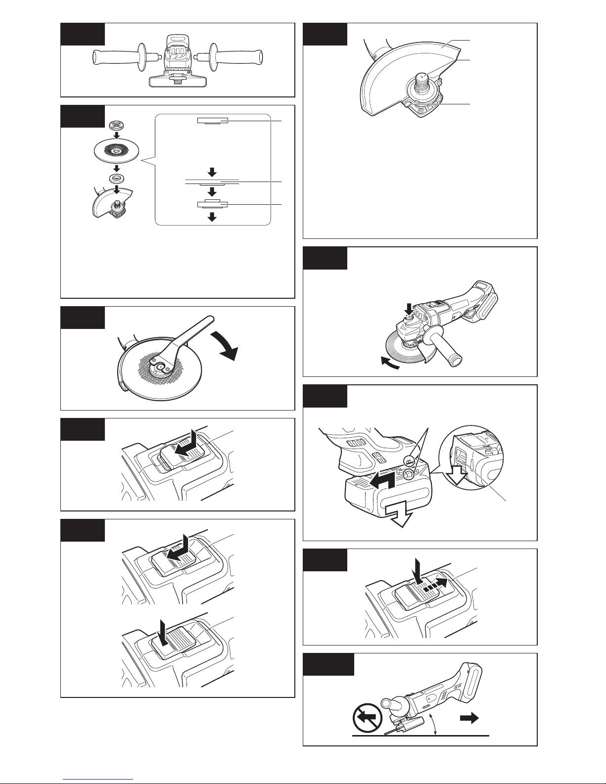
Screw the side handle securely as shown
in the figure. [Fig.1]
Never actuate the lock pin when the
spindle is rotating. The tool may be
damaged.
Press the lock button to prevent spindle
rotation when installing or removing
parts, such as grinding disc, disc guard,
etc.
Installing or removing disc
[Fig.2-5]
Inspection before use
• Has the correct grinding disc been
mounted for the object to be ground?
• Has the proper diameter of the
grinding disc been mounted for the
tool rating?
• Has the correct disc been fitted in
compliance safety standards listed
below?
U.S.A, Canada - ANSI
CAUTION
• When using, the Grinding disc guard
must be installed on the tool so that
the closed side of the guard always
faces toward the operator.
• Ensure that blotters are used when
they are provided with the bonded
abrasive product and when they are
required;
WARNING
Always use supplied guard when using
tool. Grinding disc can shatter during
use and Grinding disc guard helps to
reduce chances of personal injury.
1. Install the Grinding disc guard, and then
securely tighten the screw.
2. Install the disc flange and the disc to the
spindle in order as shown in the figure.
3. Tighten the clamp nut onto the spindle
so that hollow side faces opposite
direction to the disc.
4. Push the Spindle lock button to secure
the spindle in place, and then use the
clamp nut wrench to tighten the clamp
nut securely.
5. To remove the grinding disc, follow the
installation procedure in reverse.
Attaching or Removing
Battery Pack
CAUTION
Before inserting battery pack, check that
the power switch on the tool actuates
properly and returns to the “OFF”
position when released.
1. To connect the battery pack [Fig.6 ]:
Align the highlighted marker points
and attach battery pack.
• Slide the battery pack until it locks
into position.
2. To remove the battery pack [Fig.6 ]:
Push down the button and slide the
battery pack forward.

CAUTION
After operation, always switch off the
tool and wait until the wheel has come
to a complete stop before putting the
tool down.
Visual inspection and
workout test on disc
1. Always make sure that the disc has no
cracks before use.
2. Always give workout test on the blade
as follows.
3. Always make sure the disc is firmly
fixed.
Work out time
Brand new disc more than 3 min.
Before use on
current disc
more than 1 min.
Grinding operation [Fig.10]
ALWAYS hold the tool firmly with one
hand on grip and the other on the
support handle. Turn on the tool and
then apply the wheel or disc to the
workpiece.
In general, keep the edge of the wheel
or grinding disc at an angle of about
15º-30º to the workpiece surface.
When using a new grinding disc, do
not work the grinder in the B direction
or it will cut into the workpiece. Once
the edge of the grinding disc has
been rounded off by use, the grinding
disc may be worked in both A and B
direction.
Using a cut-off disc guard
(Available as an accessory,
not included) [Fig.11]
WARNING
• When using an abrasive cut-off disc,
be sure to use only the cut-off disc
guard designed for this use with
cut-off disc.
• NEVER use cut-off disc for grinding.
V. OPERATION
NOTE:
Be aware that this tool is always in an
operating condition, since it does not
have to be plugged into an electrical
outlet.
Power switch operation
CAUTION
• Before inserting the battery pack
into the tool, always make sure that
the power switch operates properly
and returns to the “OFF” position
when the rear of the power switch is
depressed.
• Power switch can be locked in “ON”
position. Stay alert when locking
tool in “ON” position and grasp the
tool firmly using support handle and
grip.
To start operation, press and slide the
power switch toward the “ON” position.
[Fig.7]
For continuous operation, press the
front of the power switch to lock it.
[Fig.8]
To stop the tool, press the rear of the
power switch, then it returns to the
“OFF” position. [Fig.9]
WARNING
• It should never be necessary to
force the tool. The weight of the tool
applies adequate pressure. Forcing
and excessive pressure could cause
dangerous grinding disc breakage.
• ALWAYS replace grinding disc if tool
is dropped while grinding.
• NEVER bang or hit grinding disc.
• Avoid bouncing and snagging the
grinding disc, especially when
working corners, sharp edges etc.
This can cause loss of control and
kickback.

• Do not jam the Disc or apply excessive
pressure. Do not attempt to make an
excessive depth of cut. Overstressing
the cut-off disc increases the loading
and susceptibility to twisting or
binding of the cut-off disc in the cut
and the possibility of kickback, cut-off
disc breakage and overheating of the
motor may occur.
• Do not start when disc is in the
workpiece. To do so causes the cut-off
disc binding or kickback. Let the
cut-off disc reach full speed and then
carefully cut the workpiece.
• During cutting operations, never
change the angle of the disc. Placing
side pressure on the cut-off disc (as in
grinding) will cause the disc to crack
and break, causing serious personal
injury.
CAUTION
• To prevent excessive temperature
increase of the tool surface, do not
operate the tool continuously using
two or more battery packs. The tool
needs cool-off time before switching
to another pack.
• Do not close up ventilation slots
on the sides of the body during
operation. Otherwise, the machine
function is adversely affected to
cause a failure.
• Do not strain the tool (motor). This
may cause damage to the unit.
• Use the tool in such a way as to
prevent the air from the ventilation
slots from blowing directly onto
your skin. Otherwise, you may get
burned.
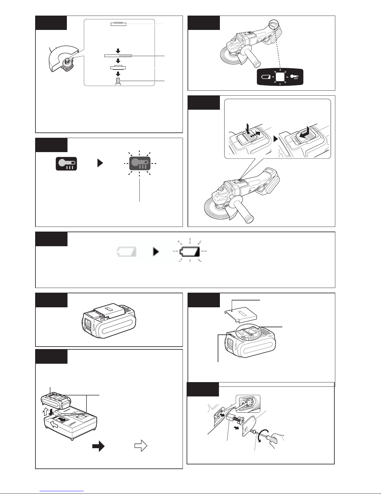
Indicator lamp for On lock
start prevention function
The grinder will not start when the
battery pack is inserted with the switch
at the ON position (switch lever at ON).
The warning lamp will flash at this
time to indicate that the ‘On lock start
prevention function’ has operated.
[Fig.12]
Press the switch to the OFF position
(switch lever at OFF) and then press it
back to the ON position (switch lever at
ON) to start the grinder. [Fig.13]
Overheat warning lamp
[Fig.14]
Indicates operation has been halted due
to motor or battery overheating.
To protect the battery, be sure to note
the following when carrying out this
operation.
• If the battery becomes hot, the
protection function will be activated
and the motor or battery will stop
operating. The overheat warning lamp
on the control panel illuminates or
flashes when this feature is active.
• If the overheating protection feature
activates, allow the tool to cool
thoroughly (at least 30 minutes).
The tool is ready for use when the
overheat warning lamp goes out.
• Avoid using the tool in a way that
causes the overheating protection
feature to activate repeatedly.
• If the tool is operated continuously
under high-load conditions or if it is
used in hot-temperature conditions
(such as during summer), the
overheating protection feature may
activate frequently.
• If the tool is used in cold-temperature
conditions (such as during winter) or
if it is frequently stopped during use,
the overheating protection feature
may not activate.
• The ambient temperature range
is between 0°C (32°F) and 40°C
(104°F). If the battery pack is used
when the battery temperature is
below 0°C (32°F), the tool may fail to
function properly.
• When charging a cool battery pack
(below 0°C (32°F)) in a warm place,
leave the battery pack at the place
and wait for more than one hour to
warm up the battery to the level of the
ambient temperature.

Battery low warning lamp
[Fig.15]
Excessive (complete) discharging of
lithium ion batteries shortens their
service life dramatically. The tool
includes a battery protection feature
designed to prevent excessive
discharging of the battery pack.
• The battery protection feature
activates immediately before the
battery loses its charge, causing the
battery low warning lamp to flash.
• If you notice the battery low warning
lamp flashing, charge the battery
pack immediately.
• If it is started with too little battery
power remaining, the tool may stop
operating without the battery low
warning lamp flashing first. This
indicates that there is too little battery
power remaining to use the tool, and
the battery pack should be charged
before further use.
• If the tool is subject to a sudden load
during use that causes the motor to
lock up, the overdischarge prevention
sensor may be triggered, and the
battery low warning lamp may flash.
The lamp will stop flashing once you
address the cause of the motor’s
locking up and cycle the trigger.
[Battery Pack]
For Appropriate Use of
Battery pack [Fig.16]
Li-ion Battery pack
• For optimum battery life, store the
Li-ion battery pack following use
without charging it.
• When charging the battery pack,
confirm that the terminals on the
battery charger are free of foreign
substances such as dust and water
etc. Clean the terminals before
charging the battery pack if any
foreign substances are found on the
terminals.
The life of the battery pack
terminals may be affected by foreign
substances such as dust and water
etc. during operation.
• When battery pack is not in use,
keep it away from other metal objects
like: paper clips, coins, keys, nails,
screws, or other small metal objects
that can make a connection from one
terminal to another.
Shorting the battery terminals
together may cause sparks, burns or
a fire.
• When operating the battery pack,
make sure the work place is well
ventilated.
• When the battery pack is removed
from the main body of the tool,
replace the battery pack cover
immediately in order to prevent dust
or dirt from contaminating the battery
terminals and causing a short circuit.
Battery Pack Life
The rechargeable batteries have
a limited life. If the operation time
becomes extremely short after
recharging, replace the battery pack
with a new one.
Battery Recycling
ATTENTION:
FOR Li-ion Battery Pack
A Li-ion battery that is recyclable
powers the product you have
purchased. Please call 1-800-8BATTERY for information on how to
recycle this battery.

Recommendations for use
[Fig.17]
Be sure to use the Pack cover
• When the battery pack is not being used,
store the battery in a way that foreign
substances such as dust and water etc.
do not contaminate the terminals. Be
sure to attach the battery pack cover to
protect the battery terminals.
• When charging the battery pack, confirm
that the terminals on the battery charger
are free of foreign substances such as
dust and water etc. Clean the terminals
before charging the battery pack if any
foreign substances are found on the
terminals. The life of the battery pack
terminals may be affected by foreign
substances such as dust and water etc.
during operation.
CAUTION
To protect the motor or battery, be sure
to note the following when carrying out
operation.
• If the battery becomes hot, the
protection function will be activated
and the battery will stop operating. The
overheat warning lamp on the control
panel illuminates or flashes when this
feature is active.
For safe use
• The battery pack is designed to be
installed by proceeding two steps for
safety. Make sure the battery pack is
installed properly to the main unit before
use.
• If the battery pack is not connected firmly
when the switch is switched on, the
overheat warning lamp and the battery
low warning lamp will flash to indicate
that safe operation is not possible, and
the main unit will not rotate normally.
Connect the battery pack into the unit
of the tool until the red or yellow label
disappears.
[Battery Charger]
Charging
CAUTION
• The charger is designed to operate
on standard domestic electrical
power only as stated in the rating
plate. Charge only on the voltage
indicated on the rating plate of unit.
e.g.120V / 60Hz.
• Do not attempt to use it on any other
voltage or frequency rating.
• The ambient temperature range
is between 0°C (32°F) and 40°C
(104°F).
• If the battery pack is used when the
battery temperature is below 0°C
(32°F), the tool may fail to function
properly.
• If the temperature of the battery pack
falls approximately below 0°C ( 32°F),
charging will automatically stop to
prevent degradation of the battery.
• Use the charger at temperatures
between 0°C and 40°C, and charge
the battery at a temperature similar
to that of the battery itself. (There
should be no more than a 15°C
difference between the temperatures
of the battery and the charging
location.)
• When charging a cool battery pack
(below 0°C (32°F) in a warm place,
leave the battery pack at the place
and wait for more than one hour to
warm up the battery to the level of
the ambient temperature.
• Cool down the charger when
charging more than two battery
packs consecutively.
• Do not insert your fingers into
contact hole, when holding charger
or any other occasions.
• To prevent the risk of fire or damage
to the battery charger.
1. Do not use power source from an
engine generator.
2. Unplug the charger when not in
use.
NOTE:
Your battery pack is not fully charged
at the time of purchase. Be sure to
charge the battery before use.

How to charge
1. Plug the charger into the AC outlet.
NOTE:
Sparks may be produced when the
plug is inserted into the AC power
supply, but this is not a problem in
terms of safety.
2. Connect the battery pack firmly into the
charger.
1. Line up the alignment marks and
place the battery onto the dock on
the charger.
2. Slide forward in the direction of the
arrow. [Fig.18 ]
3. During charging, the charging lamp
will be illuminated. When charging is
completed, an internal electronic switch
will automatically be triggered to prevent
overcharging.
• Charging will not start if the
battery pack is warm (for example,
immediately after heavy-duty
operation).The orange standby
lamp will be flashing until the battery
cools down.Charging will then begin
automatically.
4. The charge lamp (green) will flash
slowly once the battery is approximately
80% charged.
5. When charging is completed, the
charging lamp in green color will turn off.
6. If the temperature of the battery pack
is 0°C or less, charging takes longer to
fully charge the battery pack than the
standard charging time.
Even when the battery is fully charged,
it will have approximately 50% of the
power of a fully charged battery at
normal operating temperature.
7. Consult an authorized dealer if the
charging lamp (green) does not turn off.
8. If a fully charged battery pack is inserted
into the charger again, the charging
lamp lights up. After several minutes,
the charging lamp in green color will turn
off.
9. Remove the battery pack while the
battery pack release button is held up.
[Fig.18
]
LAMP INDICATIONS
Charging is completed. (Full charge.)
Battery is approximately 80% charged.
Now charging.
Charger is plugged into the AC outlet. Ready to charge.
Charging Status Lamp.
Left: green Right: orange will be displayed.
Battery pack is cool.
The battery pack is being charged slowly to reduce the load on the battery.
Battery pack is warm.
Charging will begin when temperature of battery pack drops. If the temperature of the
battery pack is -10° or less, the charging status lamp (orange) will also start flashing.
Charging will begin when the temperature of the battery pack goes up.
Charging is not possible. Clogged with dust or malfunction of the battery pack.
Turn off Illuminated Flashing
(Green)(Orange)

Replacing carbon brushes
[Fig.19]
Keep the carbon brushes clean and
free to slip in the holders. When it is
less than 5mm (3/16”) shorter both
carbon brushes should be replaced
at the same time. Use only identical
carbon brushes.
Use a screwdriver to remove the caps.
Take out the worn carbon brushes,
insert the new ones and secure the
brush caps.
To maintain product SAFETY and
RELIABILITY, repairs, any other
maintenance or adjustment should be
performed by Huskie Tools Authorized
or Factory Service Centers, always
using Huskie Tools replacement parts.
VI. MAINTENANCE
• Use only a dry, soft cloth for wiping the
unit. Do not use a damp cloth, thinner,
benzine, or other volatile solvents for
cleaning.
• In the event that the inside of the tool or
battery pack is exposed to water, drain
and allow to dry as soon as possible.
Carefully remove any dust or iron
filings that collect inside the tool. If you
experience any problems operating the
tool, consult with a repair shop.
VII. ACCESSORIES
CAUTION
• The use of any accessories not
specified in this manual may
result in fire, electric shock, or
personal injury. Use recommended
accessories only.
• Your tool is supplied with a guard
for use with a grinding disc. A cut-off
disc can also be used with a cut-off
disc guard.
Grinding Disc
• Rated speed: greater than or equal
to (2834 - 21/32” inch/min)
• Max. wheel diameter:
Φ125mm (4 - 29/32”)
• Hole diameter: Φ22mm (7/8”)
• Max. thickness: 6mm (1/4”)
Grinding Disc Guard
• WHTP-AG
Cut-off Disc
• Rated speed: greater than or equal
to (2834 - 21/32” inch/min)
• Max. wheel diameter:
Φ125mm (4 - 29/32”)
• Hole diameter: Φ22mm (7/8”)
• Flat disc only
Cut-off Disc Guard (For cut-off disc)
• WHTP-AG
Disc Flange
• EY4640K1168
Clamp Nut
• WEY4640K1178

VIII. SPECIFICATIONS
MAIN UNIT
Mounting wheel diameter Φ125mm (4 -29/32)
Spindle thread size M14
Mounting wheel hole diameter 22mm (7/8)
Weight 1.65kg (3.63lbs) (main unit only)
Overall length 300mm (11- 13/16) (main unit only)
Motor voltage DC 18 V
Rated speed
10000min-1 (rpm)
BATTERY PACK
Model No.
BP-185
Storage battery Li-ion battery
Battery voltage
18 V DC
(3.6 V × 10 cells)
BATTERY CHARGER
Model No. CH-185
Electrical rating See the rating plate on the bottom of charger
Weight 0.93 kg (2 lbs)
Charging
time
Model No.
BP-185
Full 80 min.
NOTE: This chart may include models that are not available in your area.
Please refer to the latest general catalogue.

Federal Communication Commission Interference Statement
This equipment has been tested and found to comply with the limits for a Class B digital
device, pursuant to Part 15 of the FCC Rules. These limits are designed to provide
reasonable protection against harmful interference in a residential installation. This
equipment generates, uses and can radiate radio frequency energy and, if not installed
and used in accordance with the instructions, may cause harmful interference to radio
communications. However, there is no guarantee that interference will not occur in a
particular installation. If this equipment does cause harmful interference to radio or
television reception, which can be determined by turning the equipment off and on, the
user is encouraged to try to correct the interference by one of the following measures:
• Reorient or relocate the receiving antenna.
• Increase the separation between the equipment and receiver.
• Connect the equipment into an outlet on a circuit different from that to which the
receiver is connected.
• Consult the dealer or an experienced radio/TV technician for help.
FCC Caution: To assure continued compliance, install and use in accordance with provided
instructions. Use only the battery pack specified in the instructions. Any changes or
modifications not expressly approved by the party responsible for compliance could void
the user’s authority to operate this equipment.
This device complies with part 15 of the FCC Rules. Operation is subject to the following
two conditions: (1) This device may not cause harmful interference, and (2) this device
must accept any interference received, including interference that may cause undesired
operation.
This Class B digital apparatus complies with Canadian ICES-003.
IX. APPENDIX
WARRANTY SUPPLEMENT
• The breakdown and damage caused by usage consistent for a long time (e.g.:
factory work on the assembly line, etc.) is out of warranty.
• Damage or failure caused by use of accessories that are not specified in this
manual will not be covered by warranty.
HARMONIZED STANDARDS
MAIN UNIT
Conforms to UL Std. 60745-1 & 60745-2-3
Certified to CSA Std.C22.2 No. 60745-1 & 60745-2-3
BATTERY CHARGER
Conforms to UL Std.1310
Certified to CSA Std.C22.2 No. 223-M91

195 Internationale Blvd
Glendale Heights, IL 60139
Phone 800-860-6170
Fax 800-345-3767
www.huskietools.com
 Loading...