

Page 1
GetEarthquake.com
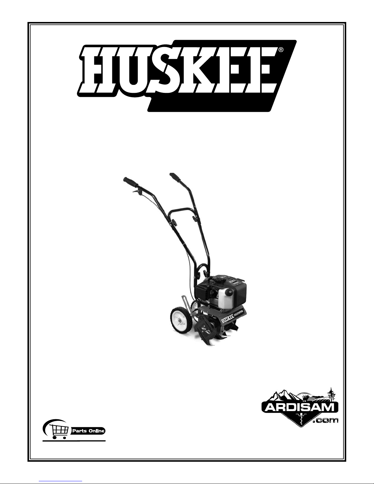
CULTIVATOR
OPERATORS MANUAL
MC43TSC
manual start
(shown)
MC43ETSC
electric start
CE Compliant
OMMC43TSC
Rev. 08/30/10
© 2010 Ardisam, Inc.
All Rights Reserved.
Page 2

Page 3

OPERATOR INSTRUCTIONS AND PARTS
GetEarthquake.com
MC43ETSC & MC43TSC Cultivator
THANK YOU AND CONGRATULATIONS!
on your purchase of a new HUSKEE® CULTIVATOR from Ardisam, Inc. We have worked to
ensure that your Huskee Cultivator will be one of the most trouble-free and satisfying pieces of
equipment you have ever owned. With proper care, your cultivator will provide many years of
service. Please take the time to read this manual carefully to learn how to correctly operate and
maintain your equipment.
CONTENTS
Registration ....................................................................................................................................................................4
Introduction .....................................................................................................................................................................4
Specifications .................................................................................................................................................................4
General Safety Rules ................................................................................................................................................. 5-8
Unpacking and Assembly ......................................................................................................................................... 9-10
Operating Your Cultivator ........................................................................................................................................ 11-14
Maintenance ........................................................................................................................................................... 15-17
Transporting and Storage .............................................................................................................................................18
Troubleshooting ............................................................................................................................................................19
Parts Diagrams & Parts Lists .................................................................................................................................. 20-27
EK43 Border-Edger Kit Installation ...............................................................................................................................28
DK43 Dethatcher Kit Installation ...................................................................................................................................29
Warranty ................................................................................................................................................................. 30-31
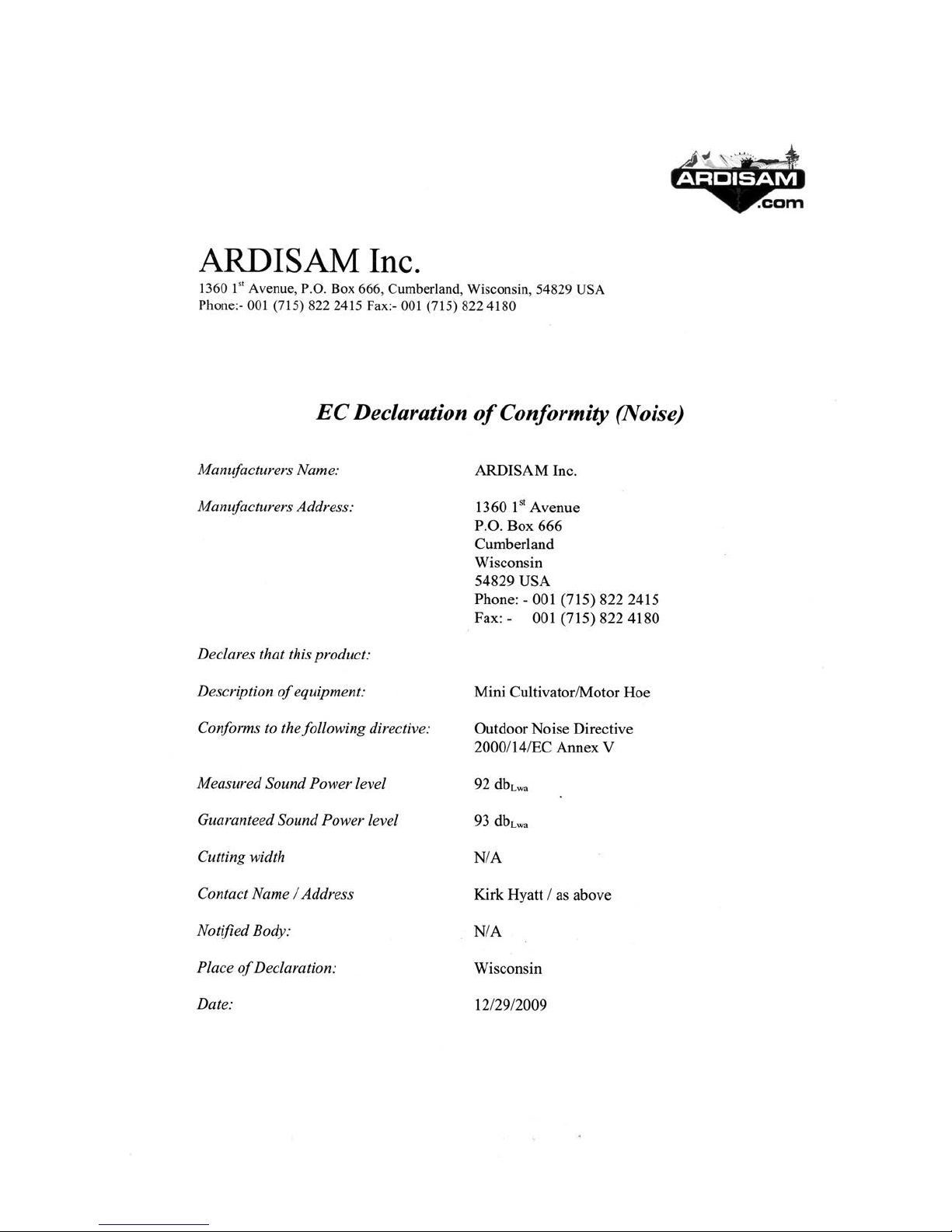
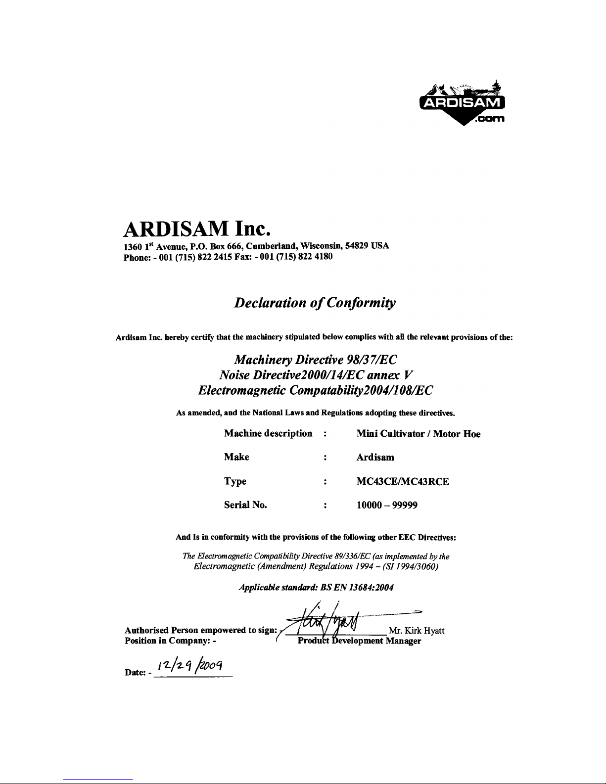
EC Declarations of Conformity ............................................................................................................................... 32-33
FEDERAL EMISSION INFORMATION
Ardisam, Inc. warrants to the retail purchaser, that this small, off-road engine was designed, built and equipped to conform at the time of initial sale to all applicable regulations of the U.S. Environmental Protection Agency (EPA).
800-345-6007
Page 3
Page 4
OPERATOR INSTRUCTIONS AND PARTS
GetEarthquake.com
MC43ETSC & MC43TSC Cultivator
REGISTRATION
Record your model number and serial number in the space provided for easy reference. Fill out and mail the registration card located in your parts
packet. Warranty is valid only if the completed registration card is received by Ardisam, Inc., within 30 days of purchase.
Model Number
Serial Number
Engine Serial Number
Date of Purchase
Place of Purchase
MC43ETSC MC43TSC
INTRODUCTION
OWNER’S RESPONSIBILITY
Accurate assembly and safe and effective use of the cultivator is the owner’s responsibility.
• Read and follow all safety instructions.
• Carefully follow all assembly instructions.
• Maintain the cultivator according to directions and schedule included in this Huskee operator’s manual.
• Ensure that anyone who uses the cultivator is familiar with all controls and safety precautions.
SPECIFICATIONS
ENGINE DISPLACEMENT
FUEL TANK CAPACITY
L/GAS RATIO
OI
IL TYPE
O
G
AS TYPE
ARK PLUG
SP
ARK PLUG GAP
SP
TRANS
G
TI
TI
TINE
W
WEI
UNIT SIZE
MISSION
EAR RATIO
LLING WIDTH
LLING DEPTH
SPEED
HEEL SIZE
GHT OF UNIT
L x W x
H (inches)
43cc
36 ounces
50:1 - 2.6 ounces per gallon
VIPER 2 CYCLE ENGINE OIL (p/n 300400)
UNLEADED REGULAR GAS
BM6A
.028
GEAR DRIVE
32:1
6 inch minimum - 10 inch maximum
4 inch maximum
250 rpm
1.375 x 7.0 inch diameter
MC43ETSC = 42 lbs. / MC43TSC = 33.5 lbs.
23” x 20” x 20”
Page 4
800-345-6007
Page 5
OPERATOR INSTRUCTIONS AND PARTS
GetEarthquake.com
MC43ETSC & MC43TSC Cultivator
GENERAL SAFETY RULES
SPECIAL MESSAGES
Your manual contains special messages to bring attention
to potential safety concerns, machine damage as well as
helpful operating and servicing information. Please read
all the information carefully to avoid injury and machine
damage.
CAUTION
AVOID INJURY! THIS SYMBOL AND TEXT HIGHLIGHT
POTENTIAL HAZARDS OR DEATH TO THE OPERATOR
OR BYSTANDERS THAT MAY OCCUR IF THE HAZARDS
OR PROCEDURES ARE IGNORED.
IMPORTANT
AVOID DAMAGE! THIS TEXT IS USED TO TELL THE
OPERATOR OF ACTIONS OR CONDITIONS THAT MIGHT
RESULT IN DAMAGE TO THE MACHINE.
NOTE: General information is given throughout the
manual that may help the operator in the operation or
service of the machine.
IMPORTANT SAFETY PRECAUTIONS
Please read this section carefully. Operate the cultivator
according to the safety instructions and recommendations
outlined here and inserted throughout the text. Anyone
who uses this cultivator must read the instructions and be
familiar with the controls.
WARNING
CALIFORNIA PROPOSITION 65 WARNING
ENGINE EXHAUST FROM THIS PRODUCT CONTAINS
CHEMICALS KNOWN TO THE STATE OF CALIFORNIA
TO CAUSE CANCER, BIRTH DEFECTS, OR OTHER
REPRODUCTIVE HARM.
This symbol points out important safety
instructions which if not followed could
endanger your personal safety. Read and
follow all instructions in this manual before
attempting to operate this equipment.
•
Do not transport the cultivator from one place to another
with the engine running.
• The tines of the cultivator should not rotate when the
engine is idling. If it does rotate when engine is idling,
contact Ardisam, Inc. for instructions.
• Dress appropriately when operating the cultivator. Always
wear sturdy footwear. Never wear sandals, sneakers, or
open shoes, and never operate the cultivator with bare
feet. Do not wear loose clothing that might get caught
in moving parts. Always wear safety glasses for eye
protection.
• Always keep hands, feet, hair and loose clothing away
from any moving parts on engine and cultivator.
• Always wear a protective hearing device.
• Do not allow children to operate this cultivator. Do not
allow adults to operate the cultivator without proper
instruction.
• Do not operate any power equipment under the influence
of alcohol or drugs.
• Keep all screws, nuts and bolts tight.
• Engine should be turned off and cool, spark plug wire
must be removed from spark plug before any repairs or
adjustments are attempted.
• Temperature of muffler and nearby areas may exceed
150° F (65° C). Avoid these areas.
• Never run engine indoors or in an enclosed area. Engine
exhaust contains carbon monoxide, an odorless and
deadly gas.
• Carefully inspect the area to be cultivated, and remove
all foreign objects. Do not cultivate above underground
utilities, including water lines, gas lines, electric cables,
or pipes. Do not operate the cultivator in soil with
large rocks and foreign objects which can damage the
equipment.
• If an object becomes lodged in the tines, turn engine off,
remove the wire from the spark plug and secure, allow
to cool before attempting to remove the foreign object.
• Use only original equipment parts from Ardisam, Inc.
including all nuts and bolts.
800-345-6007
Page 5
Page 6

OPERATOR INSTRUCTIONS AND PARTS
GetEarthquake.com
MC43ETSC & MC43TSC Cultivator
ENGINE SAFETY PRECAUTIONS
Warning Carbon Monoxide Poisoning
All engines contain carbon monoxide in their exhaust.
Carbon monoxide is a deadly, colorless, tasteless, odorless
gas which may be present even if you do not smell or see
any engine exhaust. Levels of carbon monoxide, which can
be deadly, can be present for days in an enclosed area
that has poor ventilation. Any level of carbon monoxide,
if inhaled, can cause headaches, drowsiness, nausea,
dizziness, confusion and eventually death. If you experience
any of these symptoms, seek fresh air and medical attention
immediately.
Preventing Carbon Monoxide Poisoning
• Never run engine indoors.
• Never try to ventilate engine exhaust indoors. Carbon
monoxide can reach dangerous levels very quickly.
• Never run engine outdoors where exhaust fumes may
be pulled into a building.
• Never run engine outdoors in a poorly ventilated area
where the exhaust fumes may be trapped and not easily
taken away. (Examples include: in a large hole or areas
where hills surround your working area.)
• Never run engine in an enclosed or partially enclosed
area. (Examples include: buildings that are enclosed
on one or more sides, under tents, car ports or
basements.)
• Always run the engine with the exhaust and muffler
pointed in the direction away from the operator.
• Never point the exhaust muffler towards anyone. People
should always be many feet away from the operation of
the engine and its attachments.
Gasoline Fires and Handling Fuel Safely
Fuel and fuel vapors are highly flammable. Never use fuel
where a spark or flame may be present. Never use fuel
where a potential source of ignition could occur. (Examples
include: hot water or space heaters, clothes dryer, electric
motors, etc.) Keep flames and sparks away from engine
and fuel to prevent fires. Fuel fires spread very quickly and
are highly explosive.
Prevention of Gasoline Fires
• Never fill your fuel tank with fuel indoors. (Examples
include: basement, garage, barn, shed, house, porch,
etc.)
• Always fill fuel tank outside in a well ventilated area.
• Never remove the fuel cap or add fuel with the engine
running. Stop engine and allow to cool before filling.
Never drain fuel from engine in an enclosed area.
•
• Always wipe up excess (spilled) fuel from engine before
starting. Clean up spilled fuel immediately.
• Allow spilled fuel to dry, after wiping and before
starting.
• Allow fuel fumes/vapors to escape from the area before
starting engine.
• Test the fuel cap for proper installation before starting
and using engine.
• Always run the engine with fuel cap properly installed
on the engine.
• Always unscrew gas cap vent screw while engine is
running.
• Never smoke while refilling engine fuel tank.
• Prevent fire and explosion caused by static electric
discharge. Use only nonmetal, portable fuel containers
approved by the Underwriter’s Laboratory (U.L.) or the
American Society for Testing & Materials (ASTM).
• Do not store engine with fuel in fuel tank indoors. Fuel
and fuel vapors are highly explosive.
• During storage, screw down gas cap vent screw
tightly.
• Never pour fuel from engine fuel tank.
• Never siphon fuel by mouth to drain fuel tank.
• Always have an adult fill the fuel tank.
• Never allow an adult or anyone under the influence of
drugs or alcohol to fill engine.
• Never allow children to fill the engine.
• The clutch will transfer maximum power after about two
hours of normal operation. During this break-in period
clutch slippage may occur. The clutch should be kept
free of oil or other moisture for efficient operation.
BURNS AND FIRES
The muffler, muffler guard and other parts of the engine
become extremely hot during the operation of the engine.
These parts remain extremely hot after the engine has
stopped.
Page 6
800-345-6007
Page 7

GetEarthquake.com
Prevention of Burns and Fires
• Never remove the muffler guard from the engine.
• Never touch the muffler guard because it is extremely
hot and will cause severe burns.
• Never touch parts of the engine that become hot after
operation.
• Always keep materials and debris away from muffler
guard and other hot parts of the engine to avoid fires.
This engine is designed to operate using a catalytic
converter which contributes to the engine’s compliance
with the EPA.
Steps for Working on Engine or Cultivator
1. Turn off engine switch.
2. Disconnect the spark plug wire from the spark plug.
3. Securely place the disconnected spark plug wire
away from the spark plug and any metal parts. This
must always be done or arcing may occur between
spark plug wire and metal parts.
4. Replace or repair the par
t on the engine or cultivator.
5. Check all parts that were repaired, or removed during
repair, that they are secure and fit correctly.
NOTE: All repair parts must come from the factory.
Never replace parts that are not specically designed
for the engine or cultivator.
6. Replace spark plug wire.
OPERATOR INSTRUCTIONS AND PARTS
MC43ETSC & MC43TSC Cultivator
CAUTION
HOT GASES ARE A NORMAL BY-PRODUCT OF A
FUNCTIONING CATALYTIC CONVERTER. FOLLOW ALL
SAFETY INSTRUCTIONS TO PREVENT BURNS AND
FIRES.
DO NOT ALTER/MODIFY ENGINE:
NEVER ALTER OR MODIFY THE ENGINE FROM THE
FACTORY. SERIOUS INJURY OR DEATH MAY OCCUR
IF ENGINE IS MODIFIED OR ALTERED.
WHEN WORKING ON OR REPLACING PARTS FOR
THE ENGINE OR CULTIVATOR YOU MUST ALWAYS
DISCONNECT SPARK PLUG WIRE FROM THE SPARK
PLUG AND KEEP IT AWAY FROM THE SPARK PLUG.
800-345-6007
Page 7
Page 8

OPERATOR INSTRUCTIONS AND PARTS
GetEarthquake.com
LBLMC43W
WARNING
TO AVOID SERIOUS INJURY
• Read the Operator’s Manual.
• Know the location and functions of all controls.
• Keep all safety devices and shields in place and working.
• Never allow children or uninstructed adults to operate machine.
• Shut off engine before manually unclogging tines or making repairs.
• Keep bystanders away from machine.
• Keep away from rotating parts.
• Use extreme caution when reversing or pulling the machine towards you.
WARNING
KEEP AWAY FROM ROTATING TINES
Rotating tines will cause injury.
DIELINE SIZE: 8” x 2.25”
MC43ETSC & MC43TSC Cultivator
SAFETY DECAL
This cultivator has been designed and manufactured to provide you with the safety and reliability you would expect from
an industry leader in outdoor power equipment manufacturing.
Reading this manual and the safety instructions it contains will provide you with the necessary basic knowledge to operate this equipment safely and effectively. We have placed a safety decal on the cultivator to remind you of some of this
important information while you are operating the unit.
This important safety decal is illustrated below, and is shown here to help familiarize you with the location and content of
the safety messages you will see as you perform normal cultivating operations. Please review this decal now, and if you
have any questions regarding its meaning or how to comply with these instructions, reread the complete safety instruction text in this manual, or contact your local dealer.
Should this decal become unreadable because of being worn, faded, or otherwise damaged during the use of your cultivator, please use the part number information provided to order a replacement label from your local authorized dealer.
These decals are easily applied, and will act as a constant visual reminder to you, and others who may use the equipment, to follow the safety instructions necessary for safe, effective operation of your cultivator.
Part No. LBLMC43W
Warning Decal MC43ETSC
Tine Shield Decal
Warning decals for European cultivator models
Wear ear and eye
protection while
using product
Keep a
moving parts
Page 8
way from
H
ot surfaces.
Do not tocuh.
Declared noise
level
800-345-6007
Page 9
GetEarthquake.com
UNPACKING & ASSEMBLY
UNPACK CULTIVATOR
1. Carefully lift the cultivator out of the box, remove any
packing material and cut any ties holding the handlebar
pieces to the cultivator assembly.
ASSEMBLY
1. Stand the cultivator assembly upright with tines and
wheels on a level surface. Wheels should be set in the
lowest position. DO NOT place the cultivator on a high
surface where it can fall and cause property damage
or personal injury.
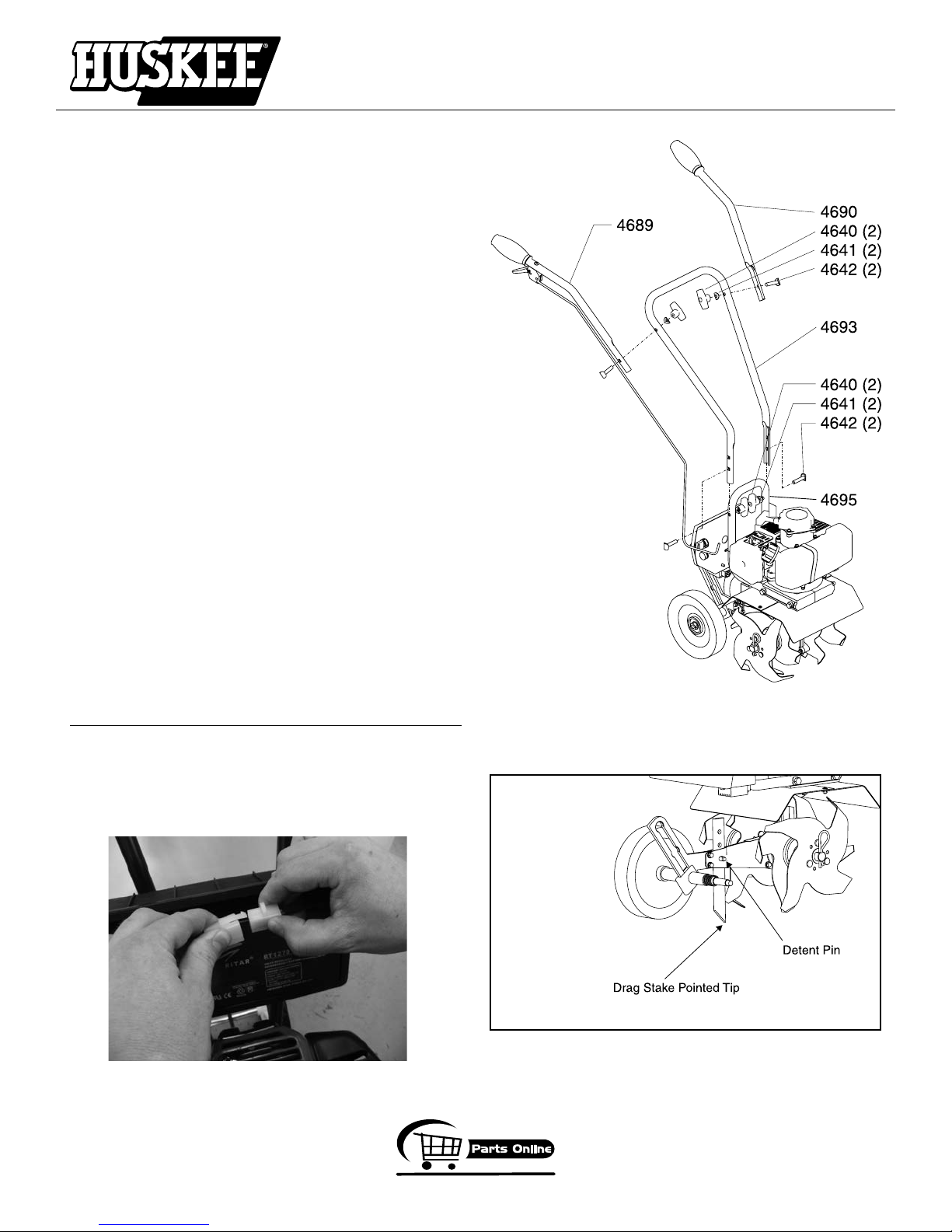
2. Using two tee handle nuts (4640), two bolts (4642),
and two curved washers (4641), assemble the middle
handlebar (4693) to the lower handlebar (4695) that
is already attached to the cultivator assembly. SEE
FIGURE 1. The middle handlebar can be installed in two
positions one high and one low. DO NOT overtighten
the tee handle nuts.
3. Attach the upper right and left handlebars (4689 & 4690)
to the middle handlebar using the two remaining tee
handle nuts, bolts, and curved washers. SEE FIGURE
1. DO NOT overtighten the tee handle nuts.
4. The drag stake is shipped with point facing upwards.
Before using, remove detent pin and turn the drag
stake around so the point is directed in the downward
position facing towards the tines. Re-insert detent pin.
SEE FIGURE 2A.
For the Electric Start Cultivator Model MC43ETSC,
remove the battery box cover and plug the white plastic
connector from the battery into the mating white plastic
connector in the battery box. SEE FIGURE 2B. Make
sure the ignition key is removed from the ignition before
connecting the wiring for the battery.
OPERATOR INSTRUCTIONS AND PARTS
MC43ETSC & MC43TSC Cultivator
FIGURE 1
(Model MC43ETSC shown. Figure 1 applies to
both models MC43TSC & MC43ETSC.)
FIGURE 2B
800-345-6007
FIGURE 2A
Page 9
Page 10

GetEarthquake.com
FOR MODEL MC43ETSC ELECTRIC START
CHARGING THE BATTERY
To charge the battery, check that the battery wiring is
properly connected and plug the battery charger (4681)
into the side of the battery box (4656) with matching
three-prong plug. Plug the other end of the battery
charger into a standard 120V outlet receptacle. Battery
is fully charged when the LED light turns GREEN
on the external charger. The electric start cultivator
(MC43ETSC) will maintain a charge in the battery when
the engine is running.
Batteries may take as long as 8 hours to fully charge
depending on the original charge level of the battery.
NOTE: For long term storage protection, be sure that
the battery is fully charged and the white plastic battery
connector is disconnected. Place the battery box cover
onto the battery box and store in a dry place out of
direct sunlight.
NOTE: Rechargeable batteries have a limited number
of charge cycles and may eventually need to be
replaced. Battery life and number of charge cycles
vary by use.
OPERATOR INSTRUCTIONS AND PARTS
MC43ETSC & MC43TSC Cultivator
WARNING
AVOID ELECTRICAL SHOCK! DO NOT USE BATTERY
CHARGER AROUND WATER OR IN WET CONDITIONS.
IMPORTANT
DO NOT SPRAY WATER ON OR NEAR THE ELECTRONICS
OF THE CULTIVATOR AS THIS MAY RESULT IN DAMAGE
TO THE ELECTRICAL COMPONENTS.
DO NOT TRY TO START ENGINE WHILE THE BATTERY
CHARGER IS CONNECTED. THIS COULD DAMAGE THE
ENGINE AND BATTERY.
Page 10
800-345-6007
Page 11
GetEarthquake.com
OPERATING YOUR CULTIVATOR
PREPARING ENGINE FOR STARTING
GAS AND OIL
Quality
To operate the engine, we recommend using “VIPER” brand
2-cycle oil (PN 300400) to ensure that the engine operates
correctly throughout the life of the engine. Use unleaded
regular gas only.
NOTE: VIPER oil can be purchased from our web site
at www.GetEarthquake.com.
Mixture
Run engine with a 50:1 ratio.
GAS OIL RATIO
1 gallon 2.6 ounces 50:1
2 gallons 5.1 ounces 50:1
5 gallons 13 ounces 50:1
MIXING FUEL AND FILLING FUEL TANK
Mixing Fuel
1. Fuel must be mixed in a container outside in a well
ventilated area.
2. Fill certified fuel container 1/4 full of recommended
fuel.
3. Add recommended amount of 2 cycle oil.
4. Screw container cap on straight and tight.
5. Shake the container to mix fuel and oil.
6. Unscrew gas cap slowly to vent, add the remainder of
fuel requirements.
7. Wipe away any spilled fuel or oil and allow to evaporate
before moving or transporting.
Filling Fuel Tank
1. Shut-off engine and allow engine to completely cool
before refilling the fuel tank.
2. Move to a well ventilated area, outdoors, away from
flames and sparks.
3. Clean debris from area around the fuel cap.
4. Loosen fuel cap slowly. Place the cap on a clean, dry
surface.
5. Carefully add fuel without spilling.
6. Do
not fill gas tank completely full, allow space for fuel
to expand.
mmediately replace fuel cap and tighten. Wipe off
7. I
spilled fuel and allow to dry before starting engine.
OPERATOR INSTRUCTIONS AND PARTS
MC43ETSC & MC43TSC Cultivator
CAUTION
NEVER STORE ENGINE WITH FUEL IN THE TANK INDOORS.
FUEL AND FUEL VAPORS ARE HIGHLY FLAMMABLE.
NE V E R MI X FUE L AND OIL DIREC T LY IN ENGINE
FUEL TANK. USE ONLY NONMETAL, PORTABLE FUEL
CONTAINERS APP ROVED BY THE UNDERWRITER’S
LABORATORY (U.L.) OR THE AMERICAN SOCIETY FOR
TESTING & MATERIALS (ASTM).
AN ADULT MUST ALWAYS HANDLE AND FILL THE
ENGINE WITH FUEL.
ALWAYS HANDLE GAS IN A WELL VENTILATED AREA,
OUTDOORS, AWAY FROM FLAMES OR SPARKS.
DO NOT START ENGINE IF FUEL IS SPILLED. WIPE OFF
EXCESS FUEL AND ALLOW TO DRY. REMOVE ENGINE
FROM AREA TO AVOID SPARKS.
IMPORTANT
THIS ENGINE USES A GAS/OIL MIXTURE. DO NOT
RUN ON STRAIGHT GAS ONLY, ENGINE DAMAGE WILL
RESULT.
DO NOT START ENGINE WITH BATTERY CHA RGE R
CONNECTED TO BATTERY. THIS COULD CAUSE DAMAGE
TO THE CULTIVATOR.
800-345-6007
Page 11
Page 12
GetEarthquake.com
NORMAL OPERATION
1. The clutch will transfer maximum power after about two
hours of normal operation. During this break-in period
clutch slippage may occur. The clutch should be kept
free of oil and other moisture for efficient operation.
2. Cultivate without placing excessive body weight on the
unit. The cultivator operates most efficiently with the
weight of the unit itself.
3. Never run engine indoors. Exhaust fumes are deadly.
Using the Screw Type, Manual Venting Gas Cap
Your cultivator is equipped with a screw type, manual
venting gas cap.
1. Before starting the engine, turn the screw in the top of
the gas cap 2-3 turns (counterclockwise) to its venting
position. DO NOT turn the screw to the point that it stops
(4-5 turns counterclockwise). To ensure that gas will
not spill during use, check that the gas cap is screwed
on tightly and the gas cap screw is in the venting
position.
2. After using the cultivator and before putting away or
transporting it in a truck bed, screw the gas cap screw
and gas cap on (clockwise) tightly. This will prevent gas
from leaking during storage. The gas cap will not leak
during storage if gas cap is tight and the screw at the
top is tight.
STARTING AND STOPPING ENGINE
• Move engine to a well ventilated area, outdoors, to
prevent carbon monoxide poisoning.
• Move to an area away from flames or sparks, to avoid
ignition of vapors if present.
• Remove all debris from air cleaner holes and gas cap
to ensure proper air flow.
COLD ENGINE START: Starting engine for first time or
after engine has cooled off or after running out of fuel.
1. Move choke lever to RUN position.
NOTE: Choke must be in the RUN position when
pushing or using the primer bulb.
2. Prime unit until primer hose is filled with gas.
NOTE: When using the primer bulb, allow the bulb
to return completely to its original position between
pushes.
OPERATOR INSTRUCTIONS AND PARTS
MC43ETSC & MC43TSC Cultivator
WARNING
MAKE SURE THE UNIT IS IN A STABLE POSITION BEFORE PULLING THE STARTER HANDLE.
WHEN THE UNIT STARTS TO FIRE OR RUN, RELEASE
THE THROTTLE CONTROL MOMENTARILY WITH YOUR
RIGHT HAND AND RETURN YOUR LEFT HAND TO THE
HANDLEBAR POSITION TO MAINTAIN CONTROL AND
STABILITY OF THE UNIT WITH BOTH HANDS.
CAUTION
IF ENGINE FAILS TO START AFTER TRYING STARTING
PROCEDURES, PLEASE CONTACT OUR CUSTOMER
SERVICE DEPARTMENT AT 800-345-6007.
STARTER ROPE CAN CAUSE AN UNANTICIPATED JERK
TOWARDS ENGINE. PLEASE FOLLOW INSTRUCTIONS
TO AVOID INJURY.
NEVER LEAVE ENGINE RUNNING WHILE UNATTENDED.
TURN OFF AFTER EVERY USE.
NEVER CARRY CULTIVATOR FROM ONE LOCATION TO
ANOTHER WHILE ENGINE IS RUNNING.
ALWAYS HANDLE FUEL IN A WELL VENTILATED AREA,
OUTDOORS, AWAY FROM FLAMES OR SPARKS.
ALWAYS WEAR A PROTECTIVE HEARING DEVICE.
DO NOT START ENGINE IF FUEL IS SPILLED. WIPE
OFF EXCESS FUEL AND ALLOW TO DRY.
Page 12
800-345-6007
Page 13

OPERATOR INSTRUCTIONS AND PARTS
GetEarthquake.com
MC43ETSC & MC43TSC Cultivator
3. Move choke lever to CHOKE position.
NOTE: CHOKE position is dened by moving the
choke lever as far to the CHOKE position as possible.
4. Push rocker switch to the ON position.
5. Squeeze throttle control with right hand. Grasp starter
handle with left hand and pull out slowly, until it pulls
slightly harder. Without letting starter handle retract, pull
rope with a rapid full arm stroke. Let it return to its original
position very slowly until unit fires or runs. Repeat this
step every time the starter rope is pulled.
NOTE: If engine fails to start after 5-6 pulls, push
primer 1 time and pull starter rope again.
6. After engine starts running, move choke lever to HALF
CHOKE position until unit runs smoothly.
NOTE: HALF CHOKE is dened when the choke
lever is between CHOKE and RUN.
7. Move choke lever to RUN position and move throttle to
desired speed.
NOTE: Run at full throttle when possible. Do not let
unit idle for extended periods of time.
8. To stop engine, push rocker switch to OFF position.
WARM ENGINE START:
1. Move choke lever to CHOKE position.
NOTE: CHOKE position is dened by moving the
choke lever as far to the CHOKE position as possible.
2. Continue with Step 4 of Cold Engine Starting.
HOT ENGINE START:
1. Continue with Step 4 of Cold Engine Starting.
2. If engine does not fire, refer to Step 1 of Warm Engine
Starting.
FOR MODEL MC43ETSC ELECTRIC START
1. Check that the battery is connected using the white
plastic connectors inside the battery box. Insert ignition
key into ignition and turn key to the START position
until engine starts running, then release key to the ON
position. DO NOT hold the ignition key in the START
position longer than 3 seconds.
2. Run engine for 30 to 45 seconds at HALF CHOKE
position until engine warms up.
3. Move choke lever to RUN position and move throttle to
desired speed.
4. To stop, turn switch to OFF position on manual start
models. On electric start, turn ignition key to the OFF
position.
DO NOT attempt to start engine in the following
ways:
• DO NOT use starting fluid.
• DO NOT spray flammable liquids or vapors into air
cleaner, carburetor or spark plug chamber.
• DO NOT remove spark plug and attempt to start engine.
Flammable fuel can spray out & ignite from a spark from
spark plug.
800-345-6007
Page 13
Page 14
GetEarthquake.com
Adjusting Wheels and Drag Stake
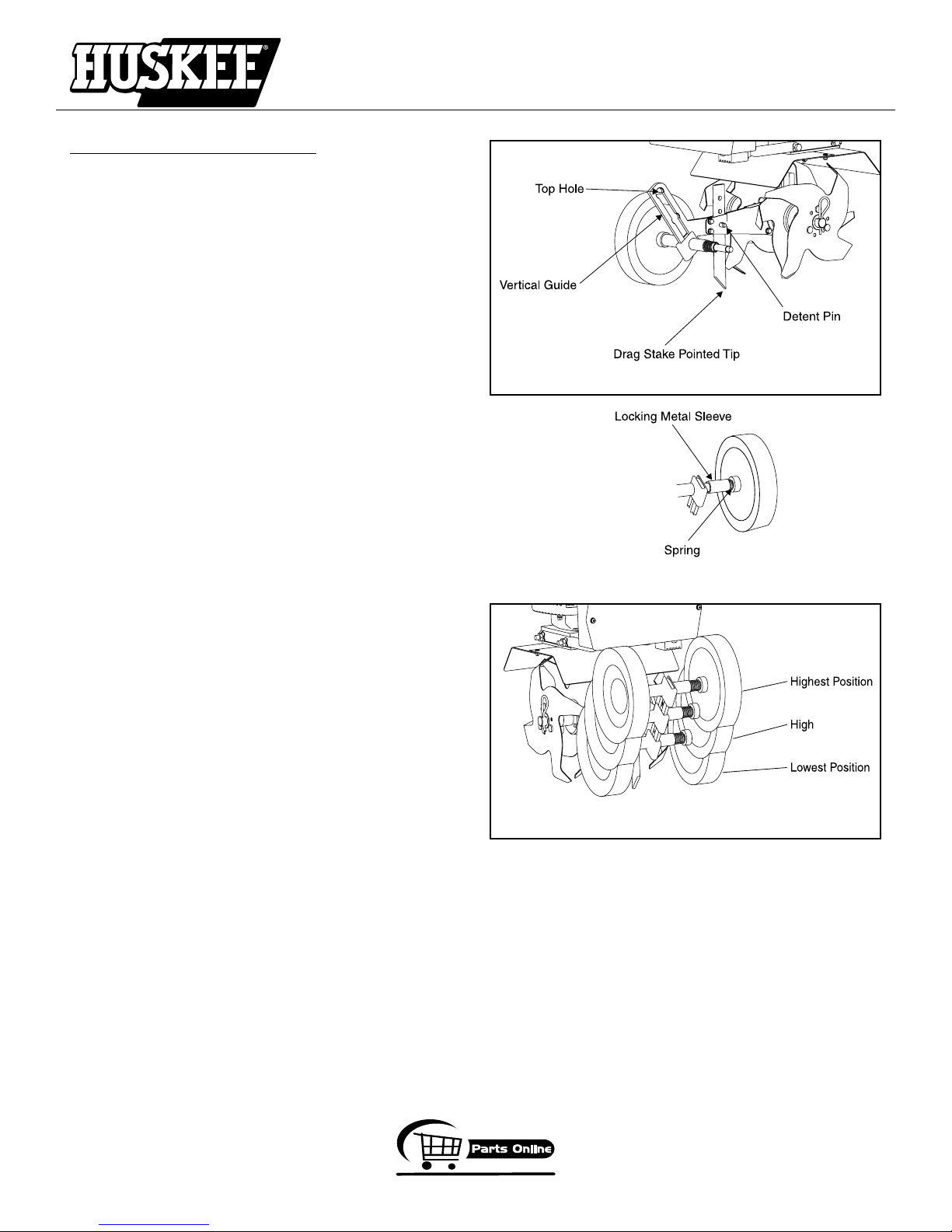
The wheels on the cultivator can be adjusted to one of
three positions. The lowest wheel position is used for
transporting the cultivator across a smooth level surface
while the engine is not running. The two higher positions
are used when cultivating in soil and help stabilize the
unit when cultivating at different depths. SEE FIGURE 6.
To adjust wheels up or down, SEE FIGURES 4 AND
5.
1. Pull the locking metal sleeve against the spring until
it releases from one of the three holes in the vertical
guide.
2. Slide the wheel set up or down to the desired
position, and release the locking metal sleeve until it
locks into one of the three holes in the vertical guide.
The drag stake is used to help regulate cultivating depth
and control the cultivator from leaping forward during
operation. Resistance to forward motion is greatest when
the drag stake is set in its lowest position allowing for
deeper cultivation.
To adjust the drag stake, SEE FIGURE 4.
1. Pull the pin out of the drag stake mount hole.
2. Position the drag stake so the pointed tip is directed
downward.
3. Insert the pin into the hole that achieves desired
depth.
OPERATOR INSTRUCTIONS AND PARTS
MC43ETSC & MC43TSC Cultivator
FIGURE 4
FIGURE 5
Page 14
FIGURE 6
800-345-6007
Page 15
GetEarthquake.com
MAINTENANCE
STEPS FOR WORKING ON EQUIPMENT
1. Turn off engine switch.
2. Disconnect the spark plug wire from the spark plug.
3. Securely place the disconnected spark plug wire away
from the spark plug and any metal parts. This must always be done or arcing may occur between spark plug
wire and metal parts.
4. Replace or repair the par
5. Check all parts that were repaired, or removed during
repair, that they are secure and fit correctly.
NOTE: All repair parts must come from the fac-
tory. Never replace parts that are not specically
designed for the cultivator.
6. Reconnect the spar
CULTIVATOR MAINTENANCE
1. The transmission case has grease installed at the factory.
It is recommended that once a year the gear case be split
by a qualified service professional and the grease level
checked. Add a molylithium type grease only if level of
grease is below top of the gears. DO NOT OVERFILL.
2. Keep all screws, nuts, and bolts tight.
3. For cold weather operation, store the unit in a cool en-
vironment. Transferring the unit from a cold to a warm
place can cause the build up of harmful condensation.
ENGINE MAINTENANCE
Please read the maintenance schedule and observe
these recommendations to extend the life of your engine.
Good maintenance is essential for safe, economical,
and trouble-free operation. It will also help reduce air
pollution. To help you properly care for your engine,
the following pages include a maintenance schedule,
routine inspection procedures, and simple maintenance
procedures using basic hand tools. Other service tasks
that are more difficult, or require special tools, are best
handled by professionals and are normally performed by
a technician or other qualified mechanic.
Maintenance, replacement or repair of the emissions
control devices and systems may be performed by any
non-road engine repair establishment or individuals.
However, items must be serviced by an authorized dealer
to obtain "no charge" emissions control service.
The maintenance schedule applies to normal operating
conditions. If you operate your engine under unusual
conditions, such as sustained high-load or high-temperature operation, or use in unusually wet or dusty conditions,
consult your servicing dealer for recommendations applicable to your individual needs and use.
t on the cultivator.
k plug wire.
OPERATOR INSTRUCTIONS AND PARTS
MC43ETSC & MC43TSC Cultivator
CAUTION
PRACTICE SAFETY AT ALL TIMES. ENGINE MUST BE
TURNED OFF AND ALLOWED TO COOL, AND SPARK
PLUG WIRE MUST BE DISC ONNE CTED BEFO RE
ATTEMPTING ANY MAINTENANCE OR REPAIR.
TO PREVENT ACCIDENTAL STARTING:
ENGINE MUST BE TURNED OFF AND COOL, AND SPARK
PLUG WIRE MUST BE REMOVED FROM SPARK PLUG
BEFORE CHECKING AND ADJUSTING ENGINE OR
EQUIPMENT.
TEMPERATURE OF MUFFLER AND NEARBY AREAS
MAY EXCEED 150° F (65° C). AVOID THESE AREAS.
CHECK CULTIVATOR OFTEN FOR LOOSE NUTS AND
BOLTS. KEEP THESE ITEMS TIGHTENED.
NEVER STORE ENGINE WITH FUEL IN THE TANK INSIDE
A BUILDING. POTENTIAL SPARKS MAY BE PRESENT
FOR IGNITION OF FUEL AND FUEL VAPORS.
AN ADULT MUST ALWAYS DO MAINTENANCE AND
REPAIR ON ENGINE AND CULTIVATOR.
ENGINE MUST BE SHUT-OFF, COOL, AND SPARK
PLUG WIRE REMOVED BEFORE ANY REPAIR OR
MAINTENANCE CAN BE DONE.
MAINTENANCE SCHEDULE
Every 8
hours
MAINTENANCE ITEM
Clean Engine and
Check Bolts & Nut
Air Filter
(See Air Filter section)
Spark Plug
(Gap .028”)
(See Spark Plug section)
* Service more frequently under dusty conditions
Check X
Clean * X
Replace X X
Check/
Adjust
Replace X
(daily)
X
Every 20
hours or
seasonally
X
Each
Year
Page 15
800-345-6007
Page 16
GetEarthquake.com
Cooling Fins
Cooling fins, air inlets and linkages must be free from any
debris before each use.
Air Filter
Never run engine without air cleaner properly installed.
Added wear and engine failure may occur if air cleaner is
not installed on engine.
Service air cleaner every 3 months or after 20 hours of operation. Clean filter daily in extremely dusty conditions.
IMPORTANT
NEVER TWIST AIR FILTERS WHEN CLEANING.
ALWAYS PRESS.
Steps for Cleaning Air Filter (Ring Style Foam Filter)
- See parts explosion on page 26.
1. Wash in warm water with liquid detergent and water until
dirt and debris are removed. Press filter when washing,
do not twist.
2. Rinse in warm water until soap and dirt are removed.
3. Dry filter by wrapping in a clean cloth and pressing filter
until it is dry.
4. Apply
5. Remo
6. Attach the filter and air cleaner cover to the engine.
a lightweight motor oil or thin based machine oil
to the entire filter.
ve excess oil.
OPERATOR INSTRUCTIONS AND PARTS
MC43ETSC & MC43TSC Cultivator
Figure 1
Figure 3
Figure 2
Figure 4
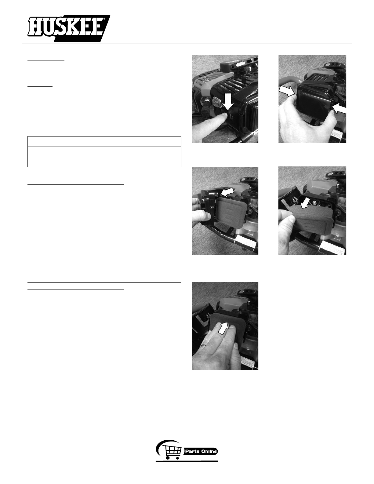
Steps for Cleaning Air Filter (Block Style Foam Filter)
- See parts explosion on page 26.
1. Before removing the air filter cover, move the choke
lever to the choke position. (Figure 1)
2. To remove air filter cover, squeeze the latch tabs on
both sides of the cover. (Figure 2)
3. Once the latch tabs are released, remove the air filter
cover by rotating the cover away from the engine.
(Figure 3)
4. Remove the foam filter element (Figure 4) and replace with a new oiled filter, or clean the original foam
filter with warm water and mild soap by following the
previous steps for Cleaning Air Filter. Remember to
thoroughly oil the foam filter with 30 or 40 weight motor oil and squeeze out any excess oil.
5. Reinstall the foam filter, pressing it evenly in place
to ensure that the foam is fully seated into its sealed
position. (Figure 5)
6. Replace the air filter cover so that it fully snaps into
place and is secured by the latch tabs. Check that the
cover is securely attached by pulling slightly on the cover. If the cover doesn’t move when pulled, it is secure.
Page 16
Figure 5
800-345-6007
Page 17
OPERATOR INSTRUCTIONS AND PARTS
GetEarthquake.com
MC43ETSC & MC43TSC Cultivator
Spark Plug
The recommended spark plug is a NGK BM6A which cross
references to a Champion CJ8.
1. Chec
2. Disconnect the spark plug cap, and clean any debris
3. Remo
4. After analysis, seat spark plug and tighten with spark
• Reinstall original spark plug, tighten additional 1/2
•
Installing new spark plug, adjust spark plug gap to .028”
NOTE: Loose spark plug may overheat and damage
engine. Over tightened spark plug may damage threads
in the cylinder head.
Carburetor
Never tamper with factory setting of the carburetor.
k spark plug at the beginning of each season.
from around the spark plug area.
ve spark plug and replace if any of the following
occur; pitted electrodes, burned electrodes, cracked
porcelain, or deposits around electrodes.
plug wrench. Reconnect the spark plug wire.
turn.
and tighten additional 1/8 – 1/4 turn .
TINE REMOVAL AND INSTALLATION
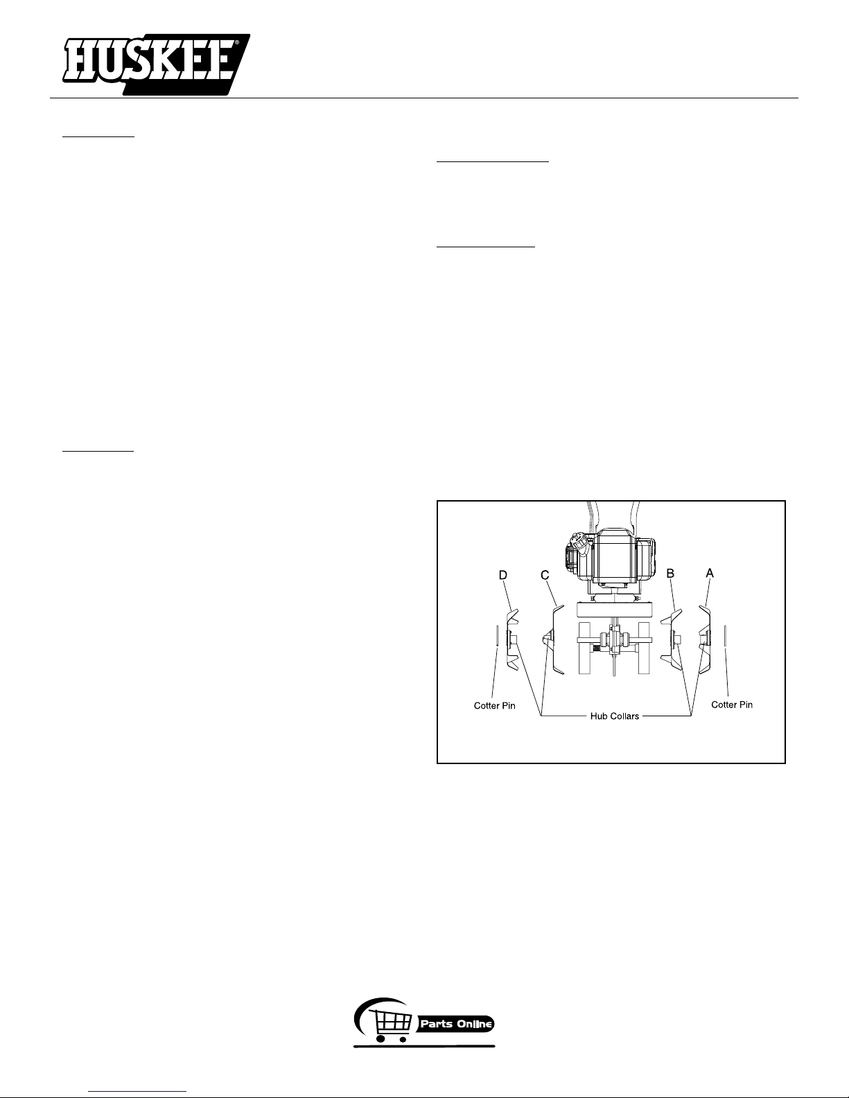
To Remove Tines
1. Remove the cotter pins from each end of the tine
shaft.
2. Slide the four tines off the shaft.
To Install Tines
1. First slide the inside tines onto each end of the tine
shaft. One inside tine is stamped with a “B” and the
other is stamped with a “C”.
2. Slide the outside tine “A” and tine “D” onto each end
of the shaft next. The tines should be installed in the
correct order so that they are positioned left to right
A, B, C, D, as viewed from the user’s position on the
cultivator. Make sure that the hub collars on both the
right and left pairs of tines face each other so that
there is adequate spacing between the tine blades.
SEE FIGURE 3.
3. Insert the cotter pins into the holes at each end of the
tine shaft to lock the tines into place.
Page 17
FIGURE 3 (Frontal View)
800-345-6007
Page 18

GetEarthquake.com
TRANSPORTING YOUR CULTIVATOR
1. After using the cultivator and before transporting it in
a truck bed, screw the gas cap screw and gas cap on
(clockwise) tightly. The gas cap will not leak during
transporting if gas cap is tight and the screw at the top
is tight. Never transport engine inside an enclosed space
within a vehicle. Fuel or fuel vapors may ignite causing
serious injury or death.
2. If fuel is present in the fuel tank, transport in an open
vehicle in an upright position.
3. If an enclosed vehicle must be used, remove gas into
an approved red fuel container. DO NOT siphon by
mouth.
4. Run engine to use up the fuel in the carburetor and fuel
tank. Always run engine in a well ventilated area.
5. Wipe away any spilled fuel from engine and cultivator.
Allow to dry.
6. Gas cap and gas cap vent screw should be turned
down tightly before transporting cultivator in a vehicle.
LONG TERM STORAGE
If your cultivator will not be used for more than one month,
prepare it for long term storage.
Steps for Long Term Storage
1. Remove the remainder of the fuel from the gas tank into
an approved fuel container.
2. Store cultivator engine in a vertical position.
3. Remove all debris from cultivator tines and engine.
SERVICE INFORMATION
At Ardisam, we build quality and durability into the design
of our products; but no amount of careful design by us, and
careful maintenance by you, can guarantee a repair-free
life for your machine. Most repairs will be minor, and easily
fixed by following the suggestions in the troubleshooting
guide in this section.
The guide will help you pinpoint the causes of common
problems and identify remedies.
For more complicated repairs, contact your place of purchase or Ardisam, Inc. for an authorized service center in
your area. Ardisam will make the necessary repairs if a
service center is not available. A parts catalog is included
in this section.
We will always be glad to answer any questions you have,
or help you find suitable assistance. To order parts or inquire
about warranty, call, write or e-mail us at the address found
below, under the section ordering repair parts.
OPERATOR INSTRUCTIONS AND PARTS
MC43ETSC & MC43TSC Cultivator
CAUTION
TO AVOID INJURY OR DEATH, NEVER SIPHON FUEL
BY MOUTH.
NEVER STORE CULTIVATOR WITH FUEL IN THE FUEL
TANK INSIDE AN ENCLOSED AREA OR BUILDING.
PRACTICE SAFETY AT ALL TIMES. ENGINE MUST BE
TURNED OFF AND ALLOWED TO COOL, AND SPARK
PLUG WIRE MUST BE DISCONNECTED BEFORE ATTE
MPTING ANY MAINTENANCE OR REPAIR.
ORDERING REPAIR PARTS
Parts can be obtained from the store where your cultivator
was purchased, direct from the manufacturer or online. To
order from the manufacturer, call, write or email:
Ardisam, Inc.
1160 Eighth Avenue, Cumberland, Wisconsin 54829
1-800-345-6007 • 1-715-822-2415
E-mail: [email protected]
Please include the following information with your order:
1. Part numbers
2. Part description
3. Quantity
4. Model number and serial number
NOTE: When ordering from the manufacturer, there
is a $10.00 minimum order.
Page 18
800-345-6007
Page 19
OPERATOR INSTRUCTIONS AND PARTS
GetEarthquake.com
MC43ETSC & MC43TSC Cultivator
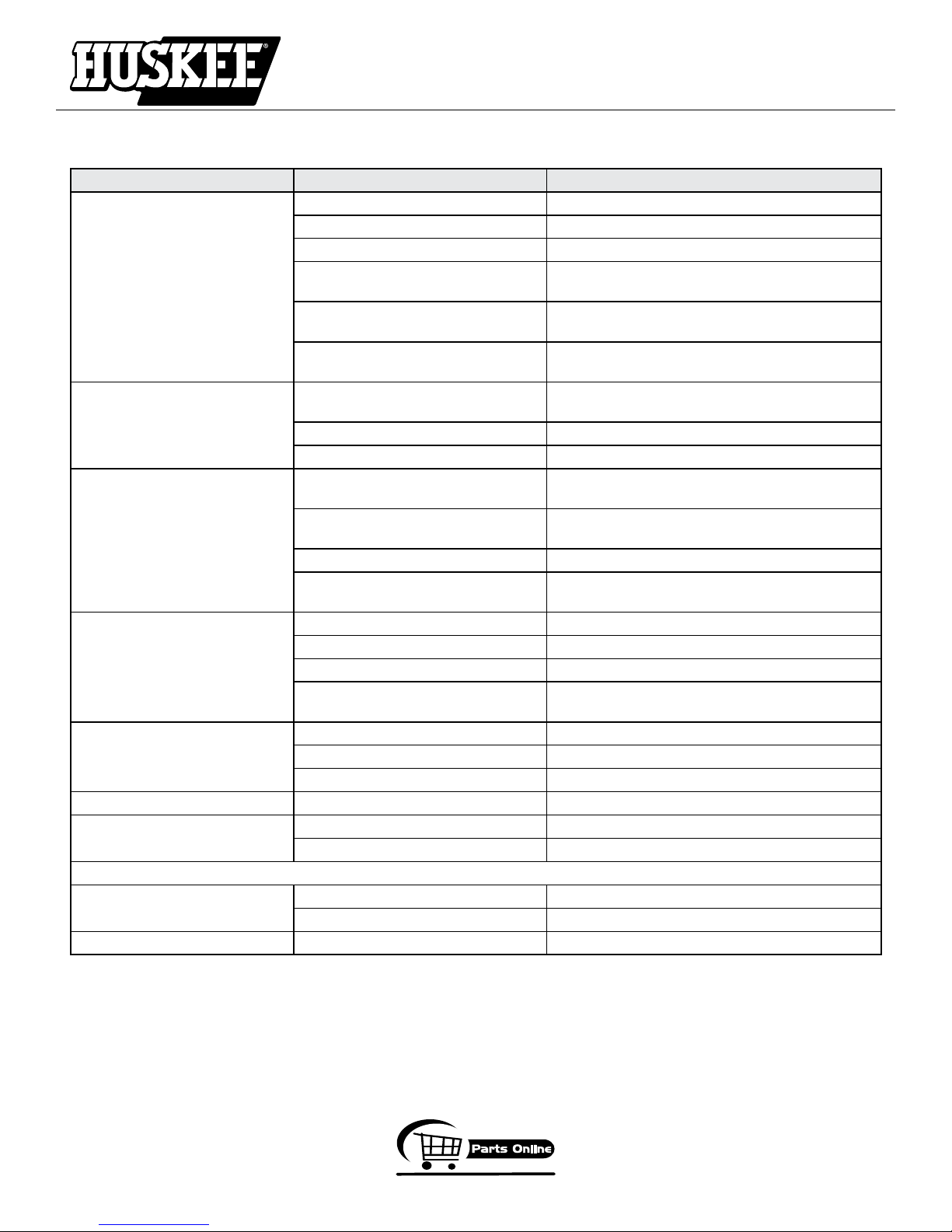
TROUBLESHOOTING
PROBLEM POSSIBLE CAUSE REMEDY/ACTION
Engine will not start 1. Power switch off 1. Flip switch to ON position
2. Spark plug wire disconnected 2. Connect spark plug wire to spark plug
3. Out of fuel 3. Refuel
4. Spark plug wet, faulty or improperly
gapped
5. Throttle control not held open 5. Hold throttle control open when pulling recoil
6. Fuel line hose not positioned in bottom of gas tank
Engine runs rough, floods during
operation
Engine is hard to start 1. Stale fuel 1. Drain old fuel and replace with fresh.
Engine misses or lacks power 1. Clogged gas tank 1. Remove and clean gas tank
Engine runs, then quits 1. Gas cap not venting 1. Clean or replace gas cap, check vent
Engine revs too high 1. Carburetor out of adjustment 1. Call factory
Tines turn at idle 1. Idle speed too high 1. Adjust idle speed lower
ODEL MC43ETSC ONLY
M
Charger won’t charge 1. Battery worn out 1. Replace with new batttery
Key won’t start machine 2. Battery not charged 1. Charge battery
Contact service provider at 800-345-6007 if above remedies fail.
1. Dirty air filter 1. Clean or replace air filter
2. Choke partially engaged 2. Turn off choke
3. Carburetor out of adjustment 3. Call factory
2. Spark plug wire loose 2. Make sure spark wire is securely attached to
3. Dirty carburetor 3. Clean carburetor, use gas stabilizer, new gas can
4. Throttle control not held open 4. Prime unit 3 more times, then hold throttle open
2. Clogged air filter 2. Clean or replace air filter
3. Carburetor out of adjustment or bad 3. Call factory
4. Spark plug wet, faulty or improperly
gapped
2. Plugged fuel filter 2. Clean or replace fuel filter
3. Carburetor out of adjustment or bad 3. Call factory
2. Broken clutch spring 2. Replace spring
2. Connectors not plugged in 2. Open battery box and connect battery connectors
4. Clean, replace or gap spark plug
handle
6. Push fuel line down into fuel in gas tank
Use gas stabilizer at end of season
spark plug
when pulling recoil handle
4. Clean, replace or gap spark plug
800-345-6007
Page 19
Page 20
GetEarthquake.com
25
18
6
24
20
21
22
7 (2)
8 (2)
9 (2)
12
1 (2)
1
3
4
17
15
16
11
13
5
8 (2)
19
26
2
27
14
23
7 (2)
8 (2)
9 (2)
10 (2)
8 (2)
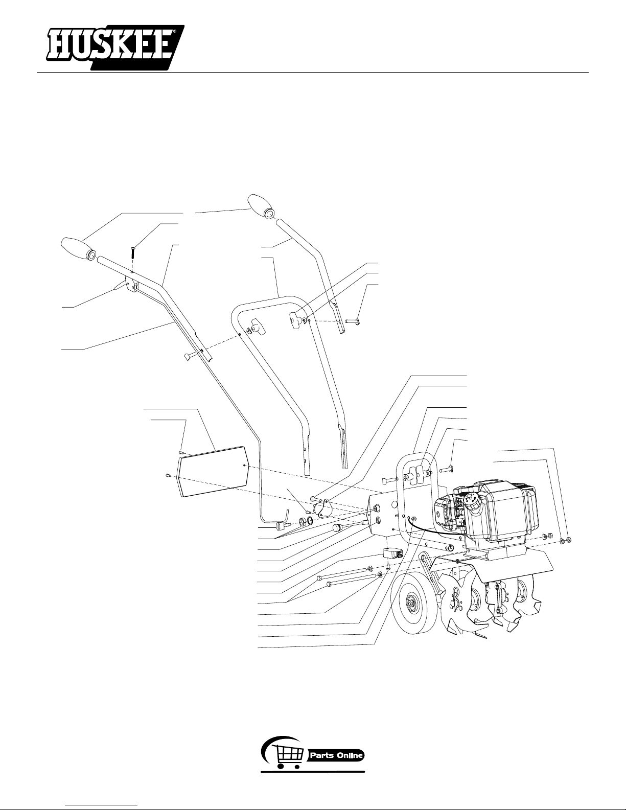
MC43ETSC HANDLEBAR PARTS
OPERATOR INSTRUCTIONS AND PARTS
MC43ETSC & MC43TSC Cultivator
Page 20
800-345-6007
Page 21
GetEarthquake.com
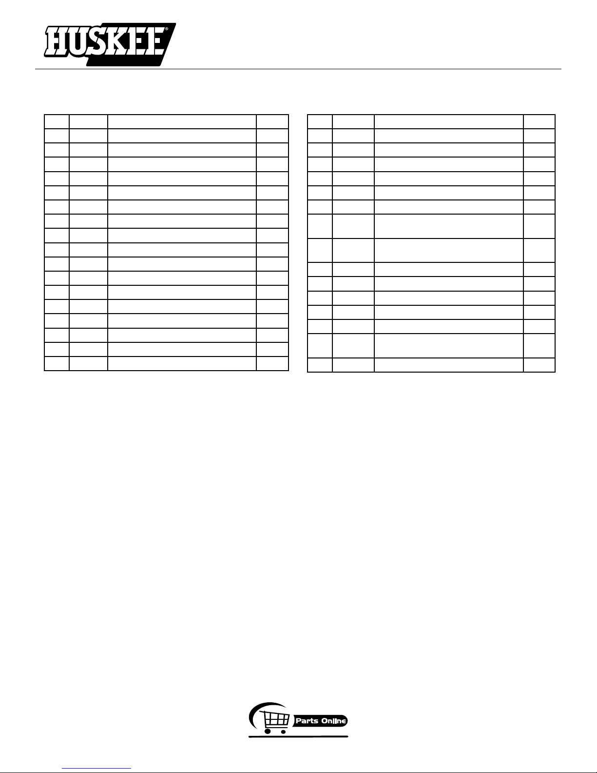
MC43ETSC HANDLEBAR PARTS LIST
OPERATOR INSTRUCTIONS AND PARTS
MC43ETSC & MC43TSC Cultivator
KEY PART # DESCRIPTION QTY.
1 300471 BOLT, M5 X 12MM 3
2 300523 GR
3 46139 KEY
4 46140 KEY SWITCH 1
5 46141 BOL
6 4639 GRIP,
7 4640 NUT, T-
8 4641 WASHER 8
9 4642 BOL
10 4655 NUT
11 4656 BATTERY BOX MC43E 1
12 4657 COVER, BATTERY BOX 1
13 4659 VOLTAGE RECTIFIER 1
14 4660 SOLENOID 1
15 4661 CHARGER PIGTAIL 1
16 4662 NUT, CHARGER PIGTAIL 1
17 4663 CAP, CHARGER PIGTAIL 1
OUND WIRE 1
ONLY 1
T, HEX HD M8 X 1.25 X 160MM 2
HANDLEBAR 2
HANDLE 4
T, HANDLE CLAMP 4
, HEX HD M8 X 1.25 2
KEY PART # DESCRIPTION QTY.
18 4667 THR
19 4669 BOLT, M6 X 1MM X 12MM PAN HD 1
20 4689 HANDLEBAR
21 4690 HANDLEBAR
22 4693 HANDLEBAR
23 4695 HANDLEBAR
24 4814 BOLT, PHILLIPS TRUSS HD ZN 10-
25 4819 TRIGGER ASSEMBLY, LONG
26 53106 NUT, LOCK BI-WAY 1/4-20 2
27 6041612 BOLT, PTH ZN 1/4-20 X 1-1/2 2
-- 46122 BA
-- 4653 FUSE
-- 4658 FUSE
-- 4675 BA
-- 4681 BA
OTTLE CABLE 1
, UPPER RIGHT 1
, UPPER LEFT 1
, MIDDLE 1
, LOWER 1
24 X 1-1/4
THROW W/O CABLE
TTERY 12V 7A (not shown) 1
HOLDER (not shown) 1
10 AMP (not shown) 1
TTERY CONNECTOR SET, WHITE
(not shown)
TTERY CHARGER (not shown) 1
1
1
1
800-345-6007
Page 21
Page 22
GetEarthquake.com
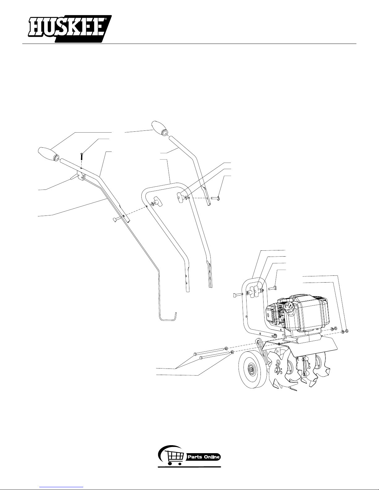
13
7
2
12
8
9
10
3 (2)
4 (2)
5 (2)
1
4 (2)
11
3 (2)
4 (2)
5 (2)
6 (2)
4 (2)
MC43TSC HANDLEBAR PARTS
OPERATOR INSTRUCTIONS AND PARTS
MC43ETSC & MC43TSC Cultivator
Page 22
800-345-6007
Page 23
GetEarthquake.com
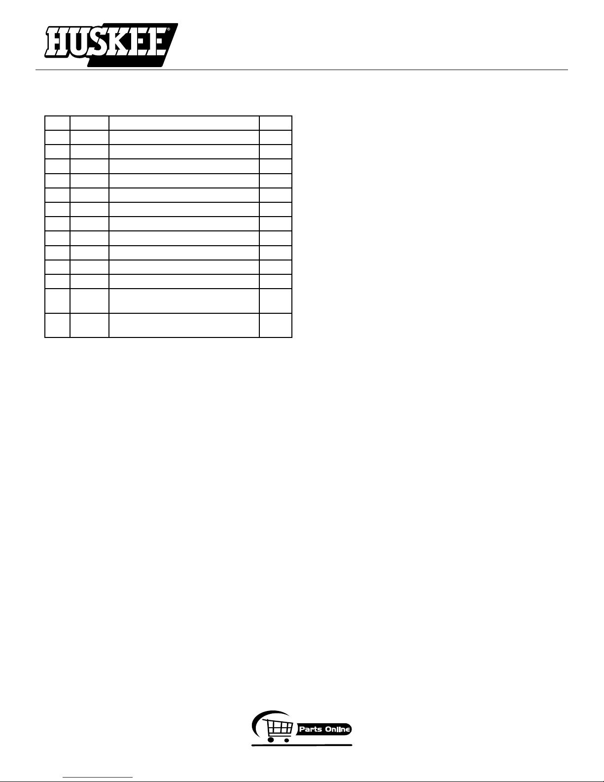
MC43TSC HANDLEBAR PARTS LIST
KEY PART # DESCRIPTION QTY.
1 46141 BOL
2 4639 GRIP,
3 4640 NUT, T-
4 4641 WASHER 8
5 4642 BOL
6 4655 NUT
7 4667 THR
8 4689 HANDLEBAR
9 4690 HANDLEBAR
10 4693 HANDLEBAR
11 4695 HANDLEBAR
12 4814 BOLT, PHILLIPS TRUSS HD ZN 10-
13 4819 TRIGGER ASSEMBLY, LONG
T, HEX HD M8 X 1.25 X 160MM 2
HANDLEBAR 2
HANDLE 4
T, HANDLE CLAMP 4
, HEX HD M8 X 1.25 2
OTTLE CABLE 1
, UPPER RIGHT 1
, UPPER LEFT 1
, MIDDLE 1
, LOWER 1
1
24 X 1-1/4
1
THROW W/O CABLE
OPERATOR INSTRUCTIONS AND PARTS
MC43ETSC & MC43TSC Cultivator
800-345-6007
Page 23
Page 24
GetEarthquake.com
23
1
15
17
3
5
16
20
18
11
2
8
7
10
7
10
4
14
1
15
17
6
9 (2)
22
19
21
24 (2)
25 (2)
12
26 (2)
13 (4)
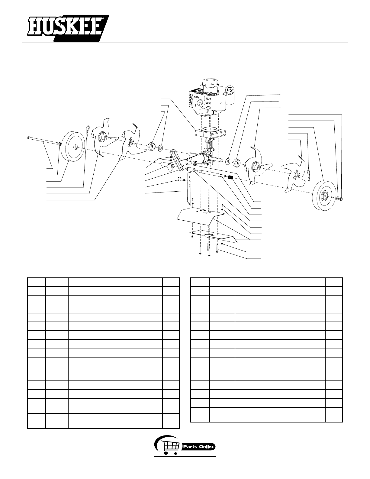
HOOD & TINES PARTS
OPERATOR INSTRUCTIONS AND PARTS
MC43ETSC & MC43TSC Cultivator
KEY PART # DESCRIPTION QTY.
1 2431 WASHER, 10MM NARROW FLAT 2
2 4600 D
3 4601 TINE “A” RIGHT OUTSIDE 1
4 4602 TINE “C” LEFT INSIDE 1
5 4603 TINE “B” RIGHT INSIDE 1
6 4604 TINE “D” LEFT OUTSIDE 1
7 4606 WASHER, FIBER 2
8 46138 TRANSMISSION ASSEMBLY 1
9 46142 BOLT M6 X 1.0 X 15MM FLANGED
10 46144 DUST CAP 2
11 46145 DETENT PIN 5/16 X 1-1/2” 1
12 46146 TINE SHIELD 2
13 4625 BOLT, M6 X 1.0 X 42MM FLANGED
14 4629 NUT M10 X 1.5 CENTER LOCK HEX HD1
RAG BAR 1
HEX HD
HEX HD
Page 24
KEY PART # DESCRIPTION QTY.
15 4634 WHEEL 2
16 4650 NUT M6 X 1.0 FLANGED HEX HD 2
17 4652 HAIR PIN, 5/8-3/4 COTTER 2
18 4673 WHEEL HOLDER 1
19 4674 WHEEL TUBE 1
20 4678 GUIDE, WHEEL TUBE 1
21 4684 TUBE, WHEEL LOCK 1
22 4685 SPRING, WHEEL LOCK 1
2
4
23 4687 BOLT M10 X 1.5 X 225MM HEX HD 1
24 4691 BOLT, M4 X 0.7 X 10MM PHILLIPS
25 4692 WASHER, M4 FLAT 2
26 4694 NUT M4 X 0.7 FLANGED HEX HD 2
-- E43CCV ENGINE 43CC CAT CONVERT 1
-- E43CCE ENGINE 43CC CAT CONVERT
2
PAN HD
1
ELEC START
800-345-6007
Page 25
GetEarthquake.com
9
15
7
19
4
16
1
17
8
22
6
19
4
10
14
11
13
5
25
21
20
23
18
20
12
10
24
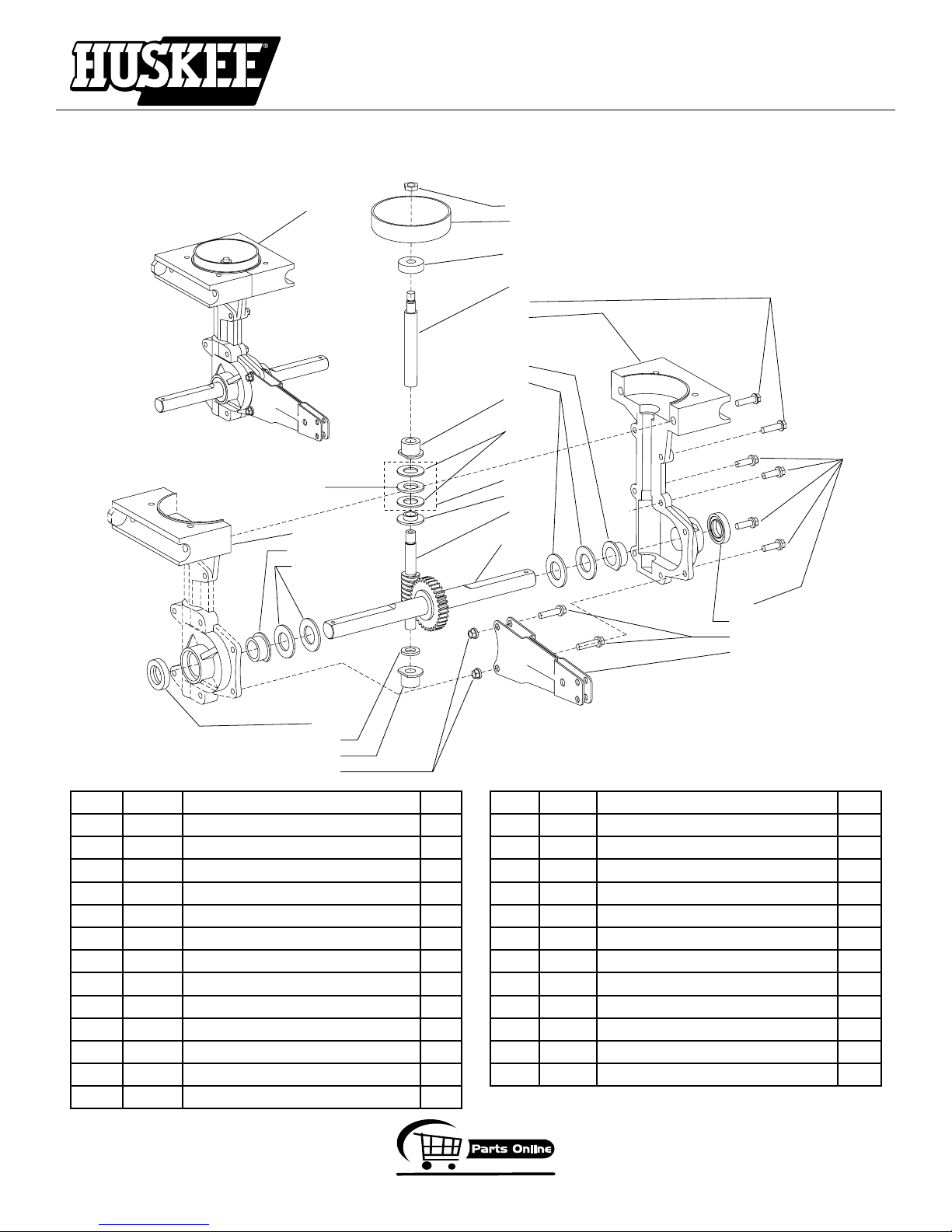
TRANSMISSION PARTS
OPERATOR INSTRUCTIONS AND PARTS
MC43ETSC & MC43TSC Cultivator
KEY PART # DESCRIPTION QTY.
1 300414 CLUTCH DRUM 1
4608 TINE SHAFT (
4609 GEAR,
4 4610 SHIM, TINE SHAFT 4
5 4613 WORM SPUD 1
6 46135 TRANSMISSION CASTING, RIGHT 1
7 46136 TRANSMISSION CASTING, LEFT 1
8 46137 DRIVE SHAFT 1
9 46138 TRANSMISSION ASSEMBLY 1
10 4614 BUSHING, DRIVE SHAFT 2
11 4615 THRUST BEARING ASSEMBLY 1
12 4616 SPACER, BUSHING 1
13 4617 REDUCER, THRUST BEARING 1
USE P/N 4651)
TINE SHAFT (USE P/N4651)
KEY PART # DESCRIPTION QTY.
14 4618 WASHER, THRUST 2
15 4619 THRUST BEARING CAGE WASHER 1
16 4620 NUT, JAM M8 1
17 4623 BALL BEARING, 9MM 1
18 4633 ARM WHEEL/DRAG STAKE MOUNT 1
19 4645 BUSHING, TINE SHAFT 2
20 4646 SEAL, TINE SHAFT 2
21 4647 BOLT, FLG HEX HD M6 X 1.0 X 18MM 4
22 4648 BOLT, FLG HEX HD M6 X 1.0 X 22MM 2
23 4649 BOLT, FLG HEX HD M6 X 1.0 X 24MM 2
24 4650 NUT, FLANGED HEX HD M6 2
25 4651 TINE GEAR & SHAFT ASSEMBLY 1
800-345-6007
Page 25
Page 26
GetEarthquake.com
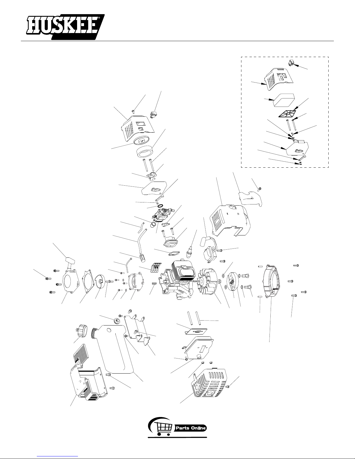
ENGINE PARTS
37
38
41
11
44 (4)
51
12
22
43
42
23
30
35
34
33
32
50 (2)
28
40
31
29
24
49 (2)
20
15
14
47 (2)
3 (2)
2
6 (2)
4
7 (2)
9
8 (2)
1
16 (2)
19
45 (2)
18
17
36
46 (2)
48 (2)
39
47 (4)
21
47
46
25
13
5
10
48 (2)
27
26
52
53
55
54
59 (2)
58 (2)
57
56
46
46
60 (2)
62
68
67
63
63
61
64
65
50
40
66
OPERATOR INSTRUCTIONS AND PARTS
MC43ETSC & MC43TSC Cultivator
AIR FILTER BLOCK STYLE
Page 26
800-345-6007
Page 27

OPERATOR INSTRUCTIONS AND PARTS
GetEarthquake.com
MC43ETSC & MC43TSC Cultivator
ENGINE PARTS LIST
KEY PART # DESCRIPTION QTY.
1 300484 FLYWHEEL, MAGNETO 1
2 300337 NUT, FLANGE M8 1
3 300462 WASHER, ROTOR 2
4 300413 CLUTCH ROTOR ASSEMBLY 1
5 300412 SPRING, CLUTCH 1
6 300449 WASHER, SPRING 2
7 300450 BOLT, SHOULDER 2
8 300467 PIN, LOCATING 2
9 300487 MOUNT RING & SHROUD 1
10 300491 RECOIL CLUTCH 1
11 300429 PLATE, RECOIL 1
12 3004121 HANDLE, STANDARD RECOIL 1
13 300430 RECOIL ASSEMBLY W/STANDARD HANDLE 1
14 300472 IGNITION COIL, MC43 1
300472CE IGNITION COIL, MC43 CE 1
300191 IGNITION
300191CE IGNITION
15 300482 SHROUD, ENGINE 1
16 300493 BOLT, STUD M6 X 62MM 2
17 300475 GASKET, MUFFLER 1
18 4813 MUFFLER 1
19 4812 COVER, MUFFLER 1
20 BM6A SPARK PLUG 1
21 300483 COVER, ENGINE SHROUD 1
22 300476 GASKET, INTAKE 1
23 300478 WINDPIPE, INTAKE 1
24 300479 GASKET, CARBURETOR 1
25 300486 CARBURETOR 1
26 300481 O-RING, CARBURETOR 1
27 3004109 PRIMER BULB 1
28 300329* INT
29 300340* CHOKE LEVER, LONG 1
30 300328* CHOKE COVER 1
31 3004132* SCREW, THROTTLE LEVER 1
32 300455 PLATE, INTAKE COVER ADAPTER 1
33 300457 COVER, AIR FILTER 1
34 300435 AIR FILTER 1
35 300330 INTAKE COVER 1
*For reference only. Contact customer service for replacement
COIL, MC43E 1
COIL, MC43E CE 1
AKE BASE ASSEMBLY (includes intake
base, long choke lever, choke cover & throttle
lever screw)
KEY PART # DESCRIPTION QTY.
36 56105 BRACKET, GAS TANK 1
37 300331 GAS TANK 1
38 300401 GAS
39 300332 SHROUD, GAS TANK 1
40 1021 ROCKER SWITCH 1
-- 1021CE ON
41 300494 GROMMET, 2-HOLE GAS TANK 1
42 300497 HOSE, PRIMER LINE 1
43 300498 HOSE, FUEL LINE 1
44 300335 BOLT W/WASHER PHILLIPS HH 4
45 300492 NUT, FLANGE M6 2
46 300471 BOLT W/WASHER M5 X 12MM 5
47 300439 BOLT W/WASHER PH M5 X 18MM 7
48 300336 BOLT HH M5 X 18MM 4
49 300438 BOLT W/WASHER M5 X 25MM 2
50 300456 BOLT M5 X 50MM 2
51 300326 GUARD 1
52 300338 KEY, FLYWHEEL 1
53 3004103 FILTER, FUEL 1
61 3004158 COVER, AIR FILTER 1
62 30041501* BASE, AIR FILTER 1
63 3004156 FO
64 3004157 PLA
65 3004153* BOL
66 3004155* W
67 3004154* NUT,
68 3004151* CHOKE
69 3004152* CHOKE
* 3004150 A
- 300410 KIT, TUNE-UP (includes spark plug, carb air
- 300470 FUEL LINE HOSE & FILTER 1
- 3004114 KIT, CARBURETOR REPAIR 1
1
- 3004118 KIT,
MC43E ELECTRIC START MODEL ONLY
54 300525 STUD BOLT M6 X 41MM 1
55 300339 KEY, ELECTRIC STARTER 1
56 300527 ST
57 300529 ST
58 300445 W
59 300438 BOLT W/WASHER M5 X 25MM 2
60 300439 BOLT W/WASHER PH M5 X 18MM 2
CAP, MANUAL VENTING 1
/OFF SWITCH WIRE ASSEMBLY
REMOTE HANDLEBAR (NOT SHOWN)
AM, AIR FILTER 1
TE, REINFORCEMENT 1
T, CHOKE LEVER 1
ASHER, CHOKE LEVER 2
NYLOC, CHOKE LEVER 1
LEVER 1
PADDLE 1
IR FILTER BASE (sold as assembly unit only) 1
filter, fuel filter, bottle of Viper 2-cycle oil &
spark plug wrench)
GAS TANK (includes gas tank, both fuel
lines, fuel filter & 2-hole grommet)
ARTER WIRE 1
ARTER MOTOR KIT (includes starter, stud
bolt, clutch drum & ground wire)
ASHER M5 2
1
1
1
* P/N 3004150 Air Filter Base sold as an assembly unit only.
800-345-6007
Page 27
Page 28
OPERATOR INSTRUCTIONS AND PARTS
GetEarthquake.com
MC43ETSC & MC43TSC Cultivator
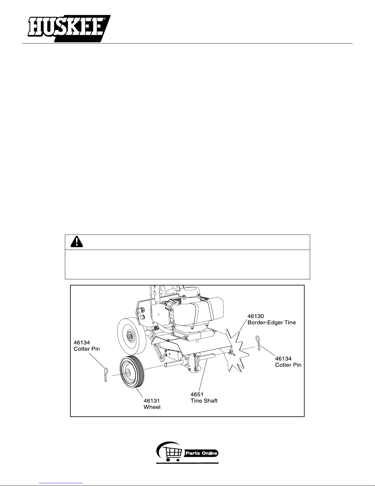
EK43 BORDER-EDGER KIT INSTALLATION (OPTIONAL ACCESSORY)
The Border-Edger Kit is a useful tool for making clean cuts in the lawn along the borders of gardens, flower beds,
walkways, and driveways for a well manicured look. To install the Border-Edger Kit, do the following:
1. Disconnect spark plug wire from spark plug.
2. Remove the cotter pins from both sides of the tine shaft.
3. Remove the cultivating tines from the shaft, remembering which direction they are facing.
4. Put the tines in a safe place and save the (2) cotter pins, they will be used on the Border-Edger Kit.
5. Slide the Border-Edger attachment on either side of the tine shaft. Make sure that the hub collar of the border
edger tine faces outward, away from the transmission of the cultivator.
6. Put (1) cotter pin, flat side facing edger attachment, through the shaft hole that is further down the shaft from the
hole where the cultivating tines were placed.
7. Slide the wheel on the opposite tine shaft.
8. Insert the remaining cotter pin, flat side facing wheel, through the hole next to the wheel at the end of the tine
shaft.
9. Re-connect spark plug wire.
10. Before using the Border-Edger Kit, remove the drag stake from the unit.
11. Set the cultivator wheels to their highest (top) position.
CAUTION
BE AWARE THAT THE CULTIVATOR COULD UNEXPECTEDLY BOUNCE UPWARD,
OR JUMP FORWARD IF THE TINES STRIKE CONCRETE, PAVEMENT, OR OTHER
HARD SURFACES OR HARD OBSTACLES BURIED UNDER GROUND.
Revised 4.16.08
Page 28
EK43 Border-Edger Attachment Kit
(fits both Models MC43TSC & MC43ETSC)
800-345-6007
Page 29
OPERATOR INSTRUCTIONS AND PARTS
GetEarthquake.com
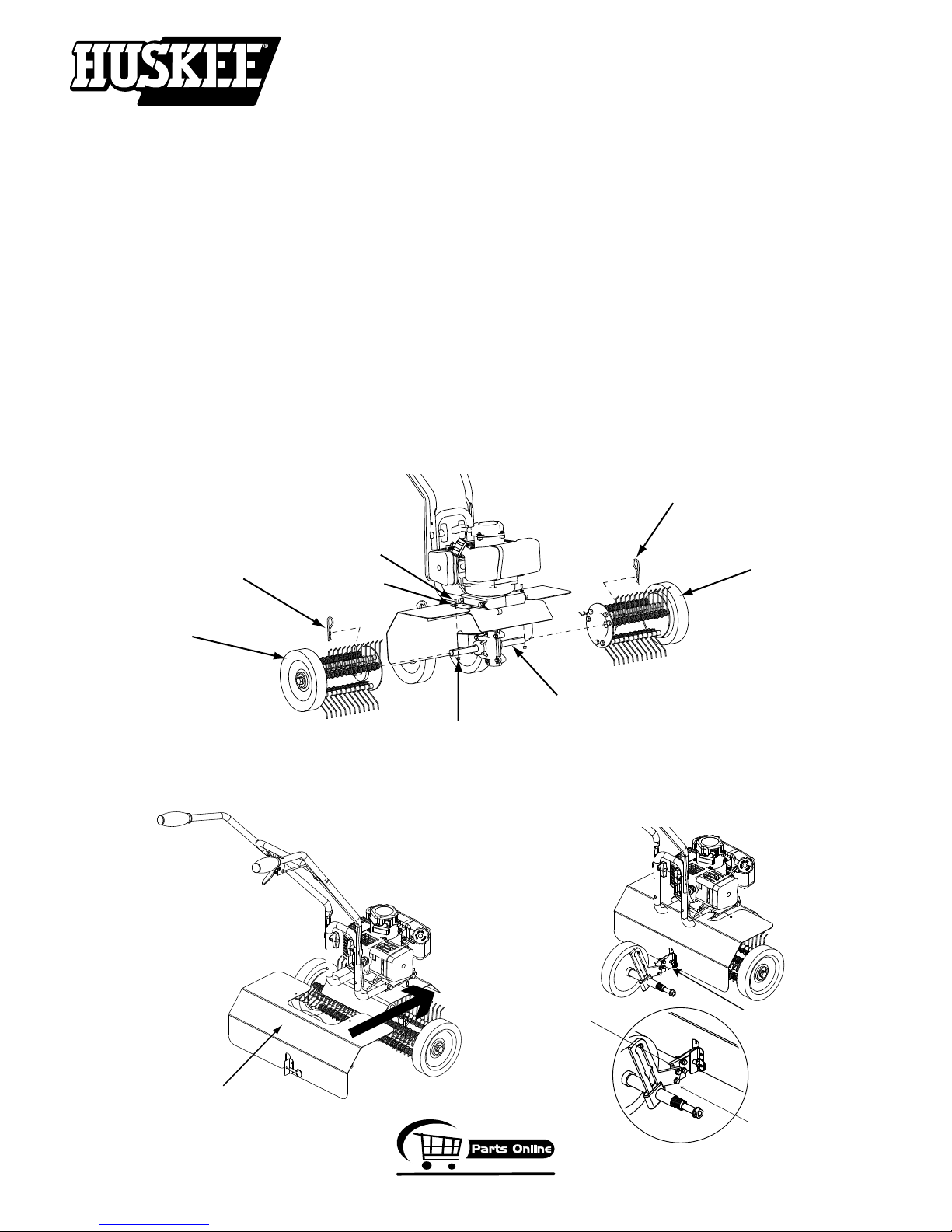
46145
Detent Pin
Nuts/Bolts (4 each)
4650/46142
4676
Plate Wheel Extension
Slide Shield Forward
4708
Right Side
Dethatcher
Assembly
4707
Left Side
Dethatcher
Assembly
46134
Hairpin
4691
Bolt
4694
Nut
4692
Washer
46134
4651
Tine Shaft
MC43ETSC & MC43TSC Cultivator
DK43 DETHATCHER KIT INSTALLATION (OPTIONAL ACCESSORY)
The Dethatcher Kit is very effective for lifting away the excessive matted layers of thatch that can prevent moisture,
oxygen and nutrients from penetrating the soil and can harbor disease and insects. Use in Spring, Summer, and Fall to
bring life and color back to your lawn.
1. Disconnect spark plug wire from spark plug. Remove the cultivating tines (if so equipped). Refer to exploded view
below for detailed assembly.
2. Slide the Left and Right Dethatcher Assemblies onto the tine shaft making sure the Right Assembly is installed on the
right side and Left Assembly is installed on the left side as defined from the user’s position.
3. Secure dethatcher assemblies using the hairpins 46134.
4. Slide dethatcher shield over the unit’s tine shield from the rear of the unit and secure using bolts 4694, washers 4692,
and nuts 4694.
5. Secure the lower part of the dethatcher shield to the drag stake mount using the detent pin 46145. Re-connect
spark plug wire.
6. Install wheel extension plate 4676 using additional bolts 46142 and nuts 4650
NOTE: The drag stake should not be used when using the dethatcher kit.
(fits both Models MC43TSC & MC43ETSC or stand-alone as MD43)
800-345-6007
DK43 Dethatcher Kit
Page 29
Page 30

MC43ETSC & MC43TSC CULTIVATOR
Warranty Terms and Conditions
PRODUCT WARRANTY: 1-YEAR LIMITED WARRANTY
Ardisam, Inc., a manufacturing company, warrants this HUSKEE® CULTIVATOR to be free from defects in the material or
workmanship for a period of one year from the date of purchase. During the one year warranty of this product, Ardisam
will furnish 100% parts and labor to correct any defect caused by faulty material or workmanship. Any unit used in a
commercial application is covered for a period of 90 days after purchase. This warranty applies to the original owner
with a proof of purchase and is not transferable. This guarantee is void unless the warranty card is properly filled out
and received by Ardisam, Inc., within 30 days of purchase or go to www.GetEarthquake.com for online registration.
For replacement par
ts, phone 800-345-6007 or go online to www.GetEarthquake.com.
ENGINE WARRANTY: 2-YEAR LIMITED WARRANTY
Ardisam, Inc., a manufacturing company warrants its Viper Engines under a two-year limited warranty to be free from
defects in materials and workmanship for the service life of the product not to exceed twenty four consecutive months from
the date of purchase for consumer applications. As an Ardisam Viper small engine owner, you are responsible for executing proper maintenance listed in your Operating and Maintenance Instructions. The warranty period begins on the date
of purchase by the first retail consumer or commercial end user, and continues for the period of time stated above.
*These warranties apply only to products which have not been subjected to negligent use, misuse, alteration, accident,
unauthorized parts, failure to use proper fuel and oil, or if repairs have been performed at non-authorized service centers.
These warranties supersede all other warranties either expressed or implied and all other obligations or liabilities on our
part. Ardisam, does not assume, and does not authorize any other person to assume for us, any liability in connection
with the sale of our products. To be at "No Charge," warranty work must be sent directly to Ardisam, Inc. or one of our
authorized service centers and performed by them. To obtain warranty service and/or replacement instructions, contact
our customer service department at 800-345-6007 Monday through Friday from 8 a.m. to 5 p.m. or visit www.ardisam.
com. If you choose to ship your product to Ardisam for warranty repair, you must first have prior approval from Ardisam
by calling our customer service department at 800-345-6007 for a return material authorization number (RMA#). Under
these circumstances, all items must be shipped prepaid. Ardisam will at no charge, repair or replace, at their discretion,
any defective part which falls under the conditions stated above. Ardisam retains the right to change models, specifications and price without notice.
H
USKEE
Ardisam, Inc.
1160 Eighth Avenue; P.O. Box 666
Cumberland, Wisconsin 54829
1-800-345-6007 · Fax (715) 822-4180
E-mail: [email protected]
Page 31

OPERATOR INSTRUCTIONS AND PARTS
GetEarthquake.com
MC43ETSC & MC43TSC Cultivator
Explanation of Emissions Control
Warranty Provisions
Viper Engines are designed, built and equipped to meet all EPA
requirements. It warrants that it is free from defects in material and
workmanship that could cause failure to the warranted part; and that
it is identical in all material respects to the engine described in the
manufacturer's application for certification. When a warrantable condition exists, Viper will repair your engine at no cost to you, including
parts and labor. The engine emissions label will indicate certification
information. If the purchaser is in need of a warrantable repair and
is not within 100 miles distance from an Ardisam authorized repair
center, Ardisam will pay for shipping costs to and from an authorized
Ardisam repair center.
Listed below are the parts covered by the emissions control systems warranty. Some parts listed below may require scheduled maintenance and
are warranted up to the first scheduled replacement point for that part.
Coverage under this warranty includes only the parts listed below (the
emission and evaporation control systems) if so equipped:
• A
ir Filter Assembly (only to the first scheduled replacement point)
• Fuel Filter (only to the first scheduled replacement point)
• Carburetor
• Fuel Lines, Fuel Line Fittings and Clamps
• Fuel Metering Valve (if equipped)
• Evaporative System (if equipped)
- Canister (if equipped)
- Canister filter (if equipped)
- Vapor hose (if equipped)
- Orifice connector (if equipped)
-Fuel tank
-Fuel cap
-Primer bulb canister (if equipped)
• Spark Plugs
• Magneto Ignition System
• Muffler Assembly
LIMITATIONS
The Emission Control Systems Warranty shall not cover any of the
following:
a) Repair or replacement required because of misuse or neglect,
improper maintenance, repairs improperly performed or
replacements not conforming to Ardisam, Inc. specifications that
adversely affect performance and/or durability and alterations
or modifications not recommended or approved in writing by
Ardisam, Inc.
b) Replacement of parts and other services and adjustments
necessary for required maintenance at or after the first scheduled replacement point;
c)
Consequential damages such as loss of time, inconvenience,
loss of use of the engine or equipment, etc.
d) Diagnosis and inspection fees that do not result in eligible
warranty service being performed; and
Any add-on or modified part, or malfunction of authorized parts
e)
due to the use of add-on or modified parts.
These items will be covered for a period of two years from the
date of the original purchase. Viper warrants that: the compo-
nents are designed, built and equipped so as to conform with all
applicable regulations adopted by the EPA; that they are free from
defects in material and workmanship that could cause failure to
the engine or other; and that the components used are identical in
all material respects to the engine described in the manufacturer's
application for certification. The warranty period begins on the
date the engine is originally purchased.
MAINTENANCE AND REPAIR REQUIREMENTS
The owner is responsible for the proper use and maintenance
of the engine. Ardisam, Inc. recommends that all receipts and
records covering the performance of regular maintenance be
retained in case questions arise. If the engine is resold during the
warranty period, the maintenance records should be transferred
to each subsequent owner. Ardisam, Inc. reserves the right to
deny warranty coverage if the engine has not been properly
maintained; however, Ardisam, Inc. may not deny warranty repairs
solely because of the lack of repair maintenance or failure to keep
maintenance records.
Normal maintenance replacement or repair of emission control devices
and systems may be performed by any repair establishment or individuals; however, warranty repairs must be performed by an Ardisam
authorized service center. Any replacement parts or service that is
equivalent in performance and durability may be used in non-warranty
maintenance or repairs, and shall not reduce the warranty obligations
of the engine manufacturer.
The warranty on emissions-related parts is as follows:
• A
ny warranted part that is not scheduled for replacement as required
maintenance in the owner's manual supplied, is warranted for the
warranty period stated above. If any such part fails during the period
of warranty coverage, that part will be repaired or replaced at no
charge to the owner. Any such part repaired or replaced under the
warranty will be warranted for the remaining warranty period.
• A
ny warranted part that is scheduled only for regular inspection
in the owner's manual supplied, is warranted for the warranty
period. Any such part repaired or replaced under warranty will be
warranted for the remaining warranty period.
• Any warranted part that is scheduled for replacement as required
maintenance in the owner's manual supplied, is warranted for the
period of time prior to the first scheduled replacement point for that
part. If the part fails prior to the first scheduled replacement, the part
will be repaired or replaced at no charge to the owner. Any such
part repaired or replaced under warranty will be warranted for the
remainder of the period prior to the first scheduled replacement point
for the part.
• A
dd on or modified parts that are not exempted by the Air
Resources Board may not be used. The use of any nonexempted
add on or modified parts by the owner will be grounds for
disallowing a warranty claim. The manufacturer will not be liable
to warrant failures of warranted parts caused by the use of a
nonexempted add on or modified part.
800-345-6007
Page 31
Page 32
Page 32
Page 33
Page 33
Page 34

OPERATOR INSTRUCTIONS AND PARTS
GetEarthquake.com
MC43ETSC & MC43TSC Cultivator
NOTES
_____________________________________________________________________________________________
_____________________________________________________________________________________________
_____________________________________________________________________________________________
_____________________________________________________________________________________________
_____________________________________________________________________________________________
_____________________________________________________________________________________________
_____________________________________________________________________________________________
_____________________________________________________________________________________________
_____________________________________________________________________________________________
_____________________________________________________________________________________________
_____________________________________________________________________________________________
_____________________________________________________________________________________________
_____________________________________________________________________________________________
_____________________________________________________________________________________________
_____________________________________________________________________________________________
_____________________________________________________________________________________________
_____________________________________________________________________________________________
_____________________________________________________________________________________________
_____________________________________________________________________________________________
_____________________________________________________________________________________________
_____________________________________________________________________________________________
_____________________________________________________________________________________________
_____________________________________________________________________________________________
_____________________________________________________________________________________________
_____________________________________________________________________________________________
_____________________________________________________________________________________________
_____________________________________________________________________________________________
_____________________________________________________________________________________________
_____________________________________________________________________________________________
Page 34
800-345-6007
Page 35

OPERATOR INSTRUCTIONS AND PARTS
GetEarthquake.com
MC43ETSC & MC43TSC Cultivator
NOTES
_____________________________________________________________________________________________
_____________________________________________________________________________________________
_____________________________________________________________________________________________
_____________________________________________________________________________________________
_____________________________________________________________________________________________
_____________________________________________________________________________________________
_____________________________________________________________________________________________
_____________________________________________________________________________________________
_____________________________________________________________________________________________
_____________________________________________________________________________________________
_____________________________________________________________________________________________
_____________________________________________________________________________________________
_____________________________________________________________________________________________
_____________________________________________________________________________________________
_____________________________________________________________________________________________
_____________________________________________________________________________________________
_____________________________________________________________________________________________
_____________________________________________________________________________________________
_____________________________________________________________________________________________
_____________________________________________________________________________________________
_____________________________________________________________________________________________
_____________________________________________________________________________________________
_____________________________________________________________________________________________
_____________________________________________________________________________________________
_____________________________________________________________________________________________
_____________________________________________________________________________________________
_____________________________________________________________________________________________
_____________________________________________________________________________________________
_____________________________________________________________________________________________
800-345-6007
Page 35
Page 36

GetEarthquake.com
Visit www.ardisam.com and discover more innovations that will
benefit you throughout the year.
Huskee, Ardisam, Inc.
1160 Eighth Avenue; P.O. Box 666
Cumberland, Wisconsin 54829
1-800-345-6007 · Fax (715) 822-4180
E-mail: [email protected]
 Loading...