

Page 1
REPARATURANLEITUNG
REPAIR MANUAL
MANUEL DE REPARATION
“
04
Edition 2004
Page 2
PREFACE
This manual contains detailed instructions on repairing the engine. It was prepared according
to the state of the art for this model series. We reserve the right to make modifications based
on technical progress without making the respective corrections in this repair manual.
This manual does not contain a description of general shop or working methods. It does not
include safety rules generally observed in workshops and is based on the assumption that the
work is performed by a mechanic who has completed his vocational training.
Please read the entire manual before starting to work.
WARNING: failing to observe these instructions can be dangerous to life and limb.
CAUTION: failing to observe these instructions may damage the motorcycle/engine components
or impair the motorcycle's traffic safety.
NOTE: provides useful information.
Only use ORIGINAL HUSABERG SPARE PARTS if parts need to be replaced.
The engine will only continue to operate safely if the prescribed service work is performed
regularly and professionally.
Subject to changes in construction and design.
C
by HUSABERG All rights reserved
Page 3

Page 4
INDEX
A
B
C
D
E
F
G
H
I
J
K
L
M
N
GENERAL INFORMATION
DISMOUNTING AND MOUNTING THE ENGINE
DISASSEMBLING THE ENGINE
SERVICING THE INDIVIDUAL PARTS
ASSEMBLING THE ENGINE
ELECTRIC SYSTEM
FUEL SYSTEM
TROUBLESHOOTING
TECHNICAL SPECIFICATIONS
PERIODIC MAINTENANCE SCHEDULE
WIRING DIAGRAMS
Page 5

TABLE OF CONTENTS
GENERAL INFORMATION
Oil circuit . . . . . . . . . . . . . . . . . . . . . . . . . . . . . . . . .A1
Engine oil . . . . . . . . . . . . . . . . . . . . . . . . . . . . . . . .A1
Checking the oil level . . . . . . . . . . . . . . . . . . . . . . .A1
Changing the engine oil . . . . . . . . . . . . . . . . . . . . .A2
Cleaning the oil screen . . . . . . . . . . . . . . . . . . . . . .A2
Changing the oil filter . . . . . . . . . . . . . . . . . . . . . . .A3
Checking the oil level in the hydraulic clutch . . . . .A4
Bleeding the clutch . . . . . . . . . . . . . . . . . . . . . . . . .A4
Cleaning . . . . . . . . . . . . . . . . . . . . . . . . . . . . . . . . .A5
Preservation for winter operation . . . . . . . . . . . . . .A5
Storage . . . . . . . . . . . . . . . . . . . . . . . . . . . . . . . . . .A5
Special tools . . . . . . . . . . . . . . . . . . . . . . . . . . . . . .A6
DISMOUNTING AND MOUNTING THE ENGINE
Dismounting the engine . . . . . . . . . . . . . . . . . . . . .B1
Mounting the engine . . . . . . . . . . . . . . . . . . . . . . .B5
Bleeding the cooling system . . . . . . . . . . . . . . . . . .B9
Adjusting the decompression cable . . . . . . . . . . . .B9
Adjusting the throttle cable . . . . . . . . . . . . . . . . . .B9
DISASSEMBLING THE ENGINE
Blocking the engine . . . . . . . . . . . . . . . . . . . . . . . .C1
Removing the rotor . . . . . . . . . . . . . . . . . . . . . . . . .C2
Removing the pressure relief valve . . . . . . . . . . . . .C2
Removing the clutch . . . . . . . . . . . . . . . . . . . . . . . .C3
Removing inner clutch hub . . . . . . . . . . . . . . . . . . .C4
Removing primary pinion and the idler shaft gear
. .C4
Removing the oil pump . . . . . . . . . . . . . . . . . . . . .C5
Removing the chain tensioner . . . . . . . . . . . . . . . .C6
Separating the timing chain . . . . . . . . . . . . . . . . . .C6
Removing the cylinder head . . . . . . . . . . . . . . . . . .C7
Separating the housing . . . . . . . . . . . . . . . . . . . . .C7
Removing the crankshaft . . . . . . . . . . . . . . . . . . . .C8
Removing the transmission . . . . . . . . . . . . . . . . . . .C8
Removing the idler shaft . . . . . . . . . . . . . . . . . . . . .C9
SERVICING THE INDIVIDUAL PARTS
Important . . . . . . . . . . . . . . . . . . . . . . . . . . . . . . . .D1
Left housing half . . . . . . . . . . . . . . . . . . . . . . . . . .D1
Right housing half . . . . . . . . . . . . . . . . . . . . . . . . . .D2
Pressure relief valve . . . . . . . . . . . . . . . . . . . . . . . .D3
Clutch cover . . . . . . . . . . . . . . . . . . . . . . . . . . . . . .D3
Crankshaft . . . . . . . . . . . . . . . . . . . . . . . . . . . . . . . .D4
Press out the crank pin . . . . . . . . . . . . . . . . . . . . . .D5
Press in the crank pin . . . . . . . . . . . . . . . . . . . . . . .D6
Checking the crankshaft journal . . . . . . . . . . . . . . .D7
Outer dimension of the crankshaft webs . . . . . . . .D7
Balancing the axial clearance of the crankshaft . . .D8
Nikasil cylinder coating . . . . . . . . . . . . . . . . . . . . . .D9
Measuring the piston and cylinder liner,
determining the piston mounting clearance . . . . .D9
Checking the piston . . . . . . . . . . . . . . . . . . . . . . .D10
Checking the piston ring end gap . . . . . . . . . . . .D10
Checking the oil pump for wear . . . . . . . . . . . . . .D10
Cylinder head top section . . . . . . . . . . . . . . . . . .D11
Cylinder head . . . . . . . . . . . . . . . . . . . . . . . . . . . .D12
Camshaft . . . . . . . . . . . . . . . . . . . . . . . . . . . . . . . .D14
Timing chain tensioner . . . . . . . . . . . . . . . . . . . . .D15
Timing train . . . . . . . . . . . . . . . . . . . . . . . . . . . . . .D15
Checking the clutch for wear . . . . . . . . . . . . . . . .D16
Checking the kickstarter for wear . . . . . . . . . . . . .D17
Shift mechanism . . . . . . . . . . . . . . . . . . . . . . . . . .D18
Assembling the main shaft (four-speed) . . . . . . . .D19
Assembling the main shaft (six-speed) . . . . . . . . .D20
Assembling the countershaft (four/six-speed) . . .D21
Starter drive . . . . . . . . . . . . . . . . . . . . . . . . . . . . .D22
Checking the freewheel. . . . . . . . . . . . . . . . . . . . .D22
Checking the freewheel hub . . . . . . . . . . . . . . . . .D22
ASSEMBLING THE ENGINE
Mounting the idler shaft . . . . . . . . . . . . . . . . . . . . .E1
Mounting the crankshaft . . . . . . . . . . . . . . . . . . . .E2
Mounting the cylinder head . . . . . . . . . . . . . . . . . .E4
Mounting the timing chain . . . . . . . . . . . . . . . . . . .E5
Mounting the timing chain tensioner . . . . . . . . . . .E7
Adjusting the valve clearance . . . . . . . . . . . . . . . . .E7
Mounting the oil pump . . . . . . . . . . . . . . . . . . . . . .E8
Mounting the shift mechanism . . . . . . . . . . . . . . . .E8
Mounting the kickstarter shaft . . . . . . . . . . . . . . . . .E9
Mounting the clutch . . . . . . . . . . . . . . . . . . . . . . . .E9
Mounting the clutch cover . . . . . . . . . . . . . . . . . .E11
Mounting the pressure relief valve . . . . . . . . . . . .E13
Mounting rotor and pick up . . . . . . . . . . . . . . . . .E13
ELECTRIC SYSTEM
Checking for loss of current . . . . . . . . . . . . . . . . . .F1
Dismounting/mounting the battery . . . . . . . . . . . . .F1
Charging the battery . . . . . . . . . . . . . . . . . . . . . . . .F1
Filling the battery . . . . . . . . . . . . . . . . . . . . . . . . . .F2
Checking the starter . . . . . . . . . . . . . . . . . . . . . . . .F2
Checking the starter relay . . . . . . . . . . . . . . . . . . . .F3
Checking the main fuse . . . . . . . . . . . . . . . . . . . . . .F3
Checking the voltage regulator . . . . . . . . . . . . . . . .F4
Kokusan 4K3B dynamic generator values . . . . . . . .F4
Troubleshooting in the ignition system . . . . . . . . . .F5
CDI unit . . . . . . . . . . . . . . . . . . . . . . . . . . . . . . . . . .F6
Checking the ignition coil . . . . . . . . . . . . . . . . . . . .F6
Ignition system . . . . . . . . . . . . . . . . . . . . . . . . . . . .F7
Checking the stator and pulse generator . . . . . . . .F7
Replacing the stator in FC models (Kokusan 4K-3A) . .
F7
Replacing the stator in FE and FS models (Kokusan 4K-3B
) . .F7
Static ignition values Kokusan 4K-3A/B . . . . . . . . .F8
Static generator values Kokusan 4K3B . . . . . . . . .F10
FUEL SYSTEM
KEIHIN FCR-MX 39/41 . . . . . . . . . . . . . . . . . . . . . .G1
Disassembling the carburetor . . . . . . . . . . . . . . . . .G2
Choke slide and hot start knob . . . . . . . . . . . . . . .G5
Accelerator pump . . . . . . . . . . . . . . . . . . . . . . . . . .G5
Jet needle . . . . . . . . . . . . . . . . . . . . . . . . . . . . . . . .G5
Float needle valve . . . . . . . . . . . . . . . . . . . . . . . . .G5
Throttle slide . . . . . . . . . . . . . . . . . . . . . . . . . . . . . .G6
Assembling the carburetor . . . . . . . . . . . . . . . . . . .G6
Adjusting the throttle sensor position . . . . . . . . .G10
Checking the throttle sensor . . . . . . . . . . . . . . . .G11
Dismounting and mounting the throttle sensor . .G11
Adjusting the idle . . . . . . . . . . . . . . . . . . . . . . . . .G12
Checking/adjusting the float height . . . . . . . . . . .G13
TROUBLESHOOTING
Troubleshooting . . . . . . . . . . . . . . . . . . . . . . . . . . .H1
TECHNICAL SPECIFICATIONS
Engine 450, 501 . . . . . . . . . . . . . . . . . . . . . . . . . . . .I1
Carburetor 450, 501 . . . . . . . . . . . . . . . . . . . . . . . . .I1
Engine 550, 650 . . . . . . . . . . . . . . . . . . . . . . . . . . . .I2
Carburetor 550, 650 . . . . . . . . . . . . . . . . . . . . . . . . .I2
Chassis . . . . . . . . . . . . . . . . . . . . . . . . . . . . . . . . . . .I3
Engine torques . . . . . . . . . . . . . . . . . . . . . . . . . . . . .I4
Chassis torques . . . . . . . . . . . . . . . . . . . . . . . . . . . .I5
Mounting clearances, engine wear limits . . . . . . . ..I6
PERIODIC MAINTENANCE SCHEDULE
FC 450, 550/4 . . . . . . . . . . . . . . . . . . . . . . . . . . . . .J1
FE 450 - 650e/6, FS 450, 650e/6 . . . . . . . . . . . . . . .J2
Additional work - driver . . . . . . . . . . . . . . . . . . . . . .J3
Additional work - workshop . . . . . . . . . . . . . . . . . ..J4
WIRING DIAGRAMS
FC models . . . . . . . . . . . . . . . . . . . . . . . . . . . . . . . .K1
FE models . . . . . . . . . . . . . . . . . . . . . . . . . . . . . . . .K2
FE USA models . . . . . . . . . . . . . . . . . . . . . . . . . . . .K4
FS models . . . . . . . . . . . . . . . . . . . . . . . . . . . . . . . .K6
Cable colors . . . . . . . . . . . . . . . . . . . . . . . . . . . . . .K8
Page 6
ENGINE OIL
Only use fully synthetic brand-name engine oils (e.g.:
Motorex Power Synt. 4T) that meet or exceed the Jaso
T903 MA quality requirements (information on the can).
CAUTION: not enough engine oil or low-quality
oil will lead to premature engine wear.
CHECKING THE ENGINE OIL LEVEL
NOTE: the engine oil level can be checked
when the engine is cold or warm.
–Place the motorcycle on a level surface (not on the
side stand).
If the engine is cold, the engine oil should be visible at
the lower edge (A) of the inspection glass.
If the engine is warm, the engine oil should reach the
upper edge (B) of the inspection glass.
Add engine oil if necessary.
CAUTION: not enough engine oil or low-quality
oil will lead to premature engine wear.
– Check the engine for leakage.
GENERAL INFORMATION
A
1
A
B
0°C
32°F
10W/50
5W/40
JASO T903 MA
TEMPERATURE
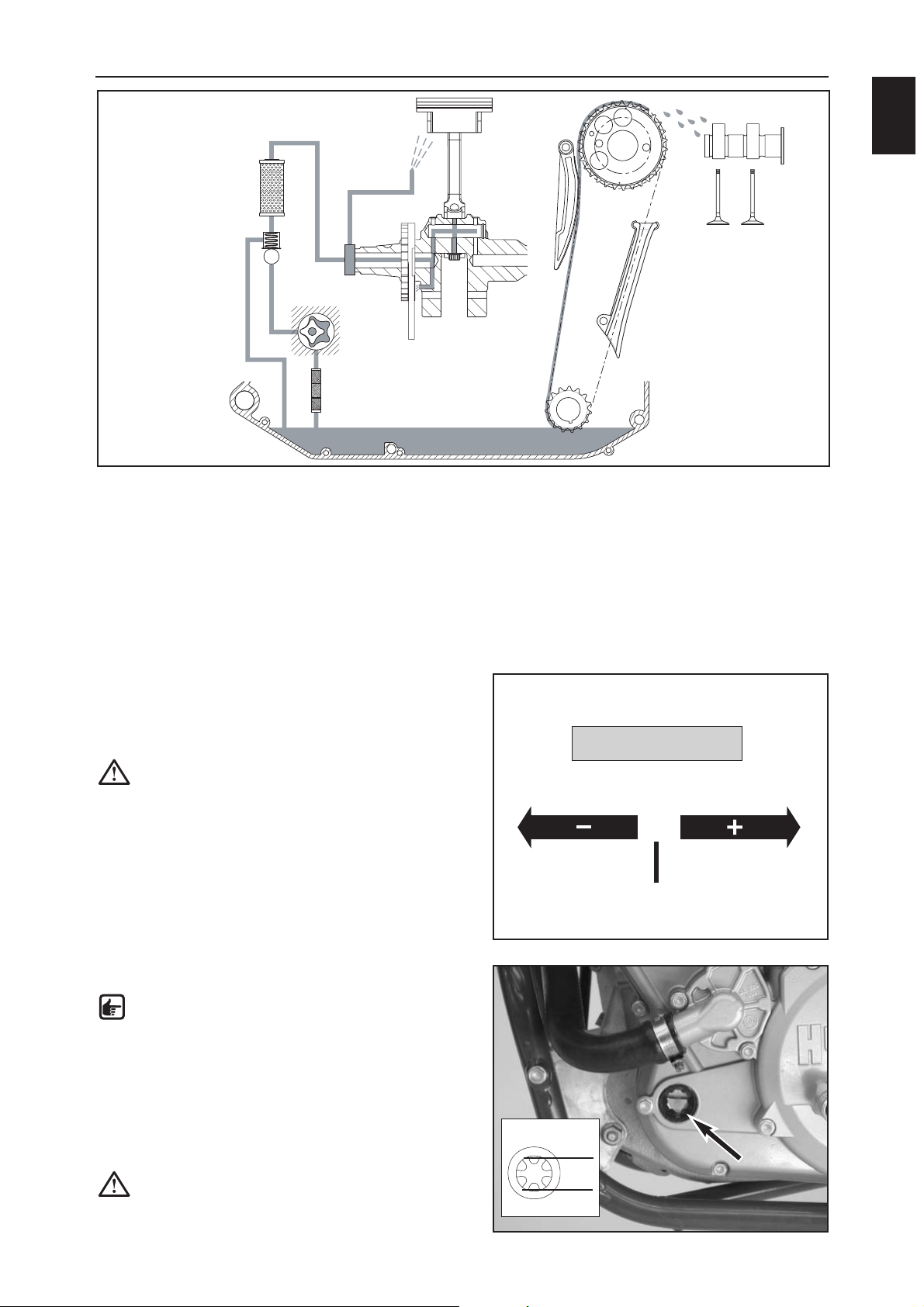
OIL CIRCUIT
DESCRIPTION:
The oil pump (1) draws the engine oil from the oil sump through the oil screen (2) and pumps it past the pressure
relief valve (3) to the oil filter (4). It continues to the crankshaft (5), partly branching off through a hole to lubricate
and cool the piston (6) and the piston pin bearing. Once through the crankshaft, the engine oil is pumped to the
conrod bearing (7) and branches off again to the bearings in the balance weight (8).
The camshaft (9) is lubricated by the engine oil which is transported to the cylinder head by the timing chain (10).
On the downward movement of the piston, engine oil is pressed from the crankcase through the diaphragm
valve (not depicted) to the transmission and shift mechanism.
1
2
3
4
6
5
8
7
9
10
Page 7
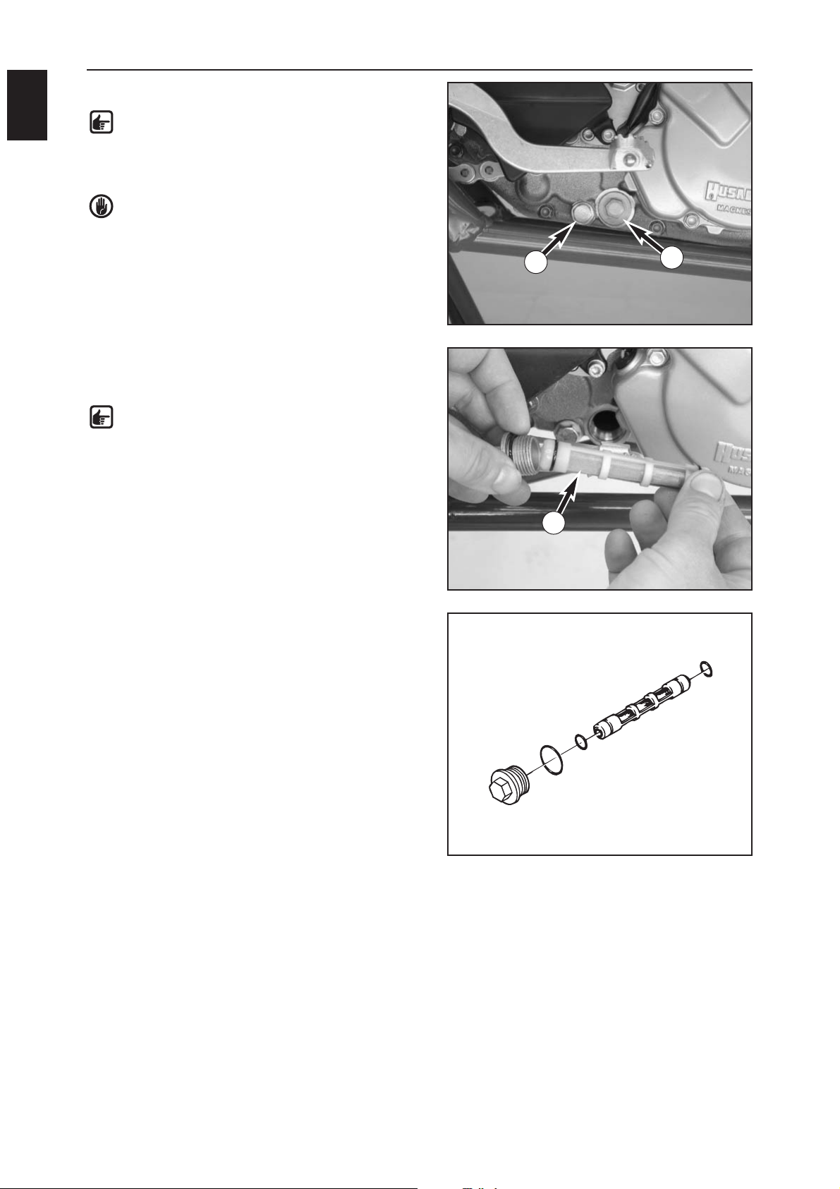
CHANGING THE ENGINE OIL
NOTE: Replace the oil screen and the oil filter
when you change the engine oil.
Change the engine oil when the engine is at
operating temperature.
WARNING: the engine oil will be very hot when
the engine is at operating temperature – be
careful not to burn yourself.
– Place the motorcycle on a level surface, remove the
plug (1) and allow the oil to drain into a suitable vessel.
– Thoroughly clean the plug (with the magnet).
– After the oil is completely drained, clean the sealing
area, mount the plug with a new seal ring and tighten
to 20 Nm.
CLEANING THE OIL SCREEN
NOTE: the oil screen (3) is located in the plug
with the hexagon drive (2) next to the oil drain
plug on the right side of the engine.
–Dismount the plug with the oil screen, thoroughly
clean the parts and blow clean with compressed air.
– Check the O-rings (4) for damage and replace if
necessary.
– Insert the oil screen in the plug, mount and tighten the
plug to 15 Nm.
GENERAL INFORMATION
A
2
1
2
3
4
4
Page 8
GENERAL INFORMATION
A
3
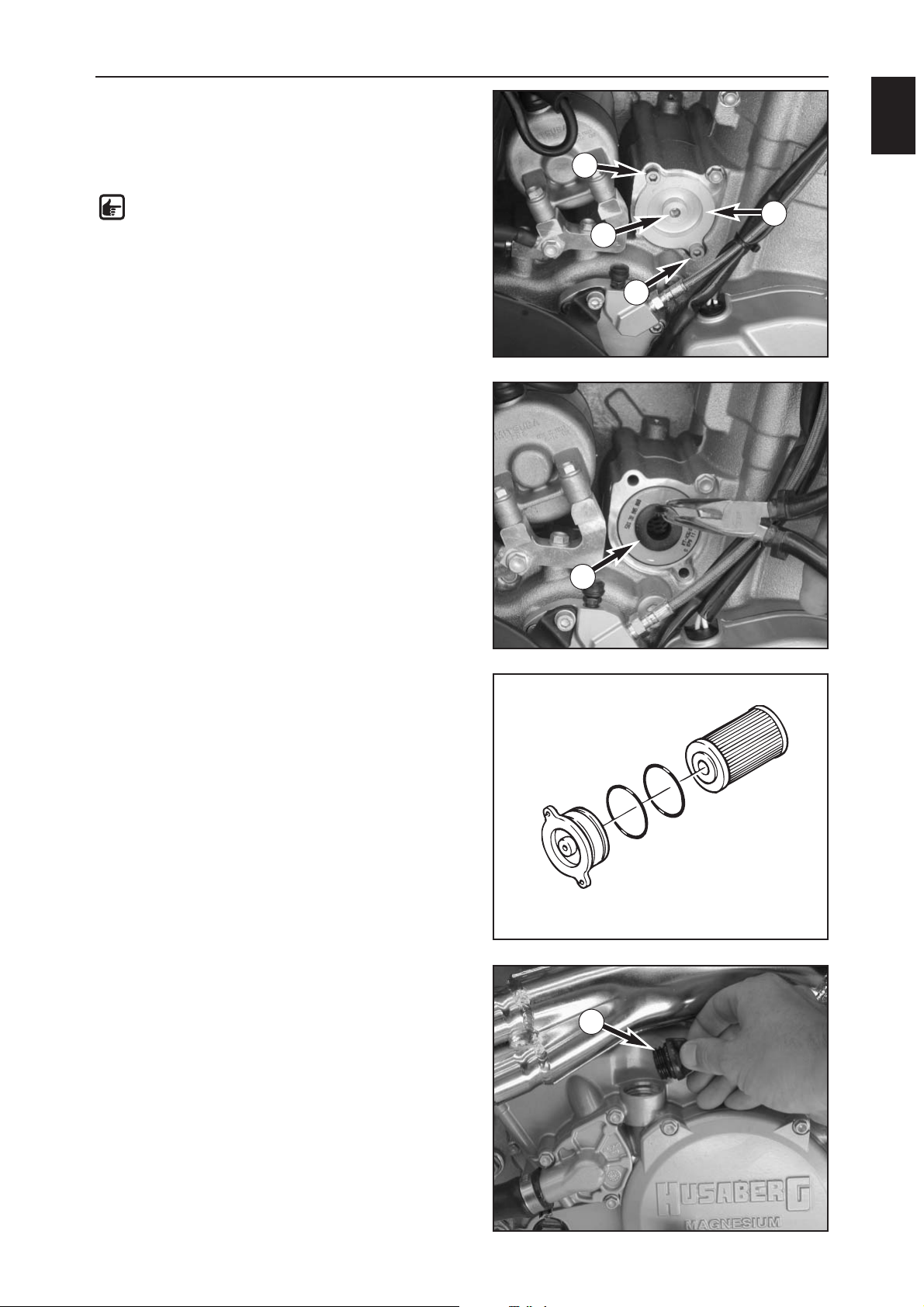
CHANGING THE OIL FILTER
– Place a suitable vessel under the engine to allow the
oil to drain.
– Remove both bolts (1) and screw an M6 bolt in the
center hole (2) of the oil filter cover.
NOTE: only tighten the bolt by hand, otherwise
you will damage the oil filter cover.
– Pull the oil filter cover (3) out of the hole with the bolt
M6 and remove the bolt.
– Use pliers to pull the oil filter element (4) from the
housing.
– Clean the oil filter cover, the sealing areas on the
O-rings and the engine case. check the O-rings (5) in
the oil filter cover for damage and replace if necessary.
– Lay the motorcycle down and fill the oil filter housing
approx. half-full with engine oil. Insert the oil filter in
the housing.
–Grease the O-rings in the oil filter cover and mount the
cover. Mount the bolts and tighten to 6 Nm.
–Place the motorcycle in an upright position again.
– Unscrew the oil filler plug (6) and add 1 liter of fully
synthetic engine oil (e.g.: Motorex Power Synt. 4T).
–Start the engine and check all of the plugs and the oil
filter cover for leakage.
– Finally, check the engine oil level and correct if
necessary.
1
1
2
3
4
6
5
5
Page 9
GENERAL INFORMATION
A
4
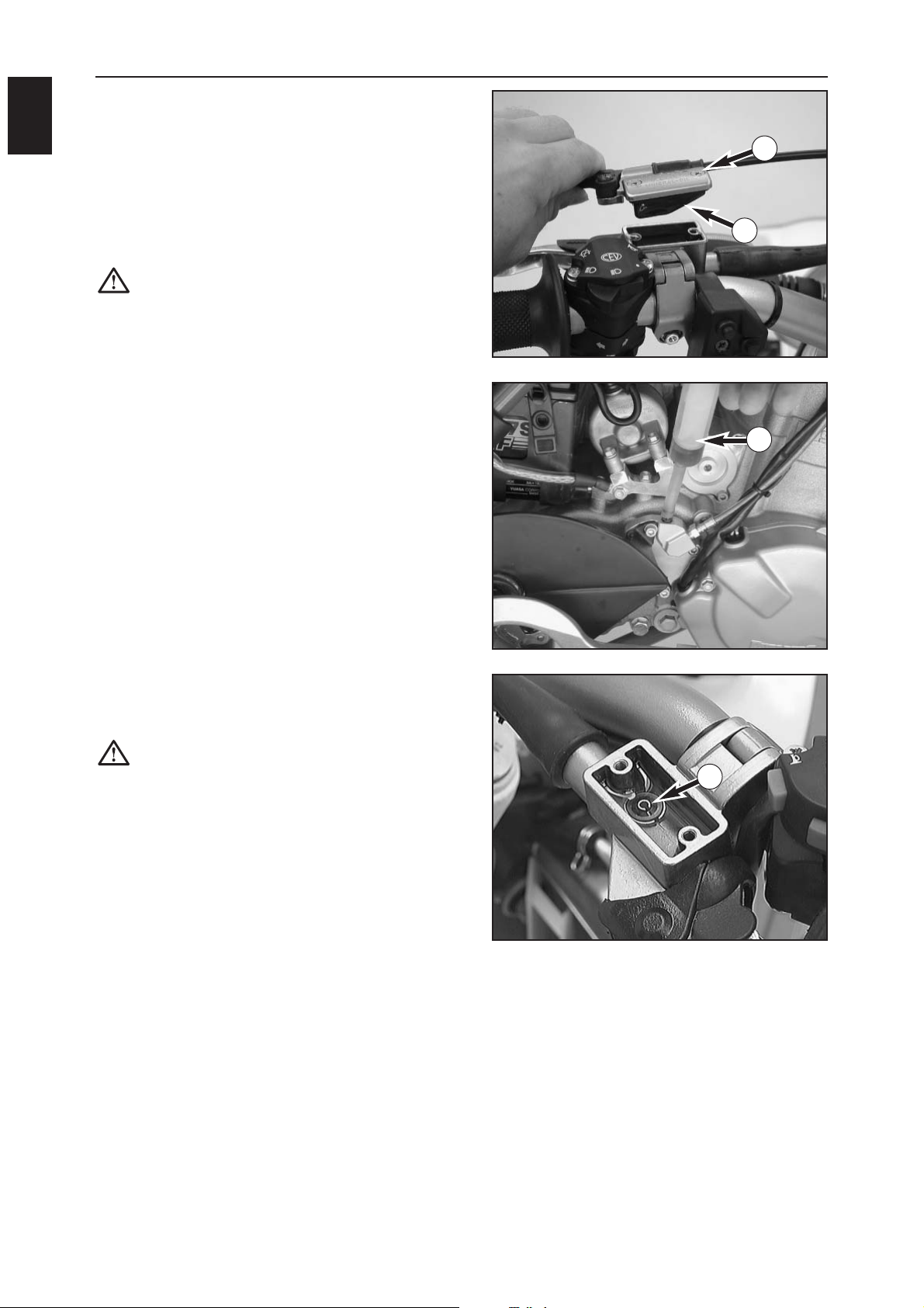
CHECKING THE OIL LEVEL IN THE
HYDRAULIC CLUTCH
Remove the cover to check the oil level in the master
cylinder of the clutch. Remove the screws (1) and lift off
the cover together with the rubber boot (2). The oil level
should be 4 mm below the upper edge when the master
cylinder is in a horizontal position. If necessary, add SAE
10 biodegradable hydraulic oil (e.g.: Motorex clutch fluid
75).
CAUTION: only fill SAE 10 biodegradable
hydraulic oil into the master cylinder. Do not
add brake fluid.
BLEEDING THE CLUTCH
To bleed, remove the cover on the master cylinder of the
clutch. Remove the screws (1) and lift off the cover
together with the rubber boot (2). Remove the vent
nipple from the slave cylinder of the clutch. Mount the
bleeder syringe (3) filled with SAE 10 biodegradable
hydraulic oil (e.g.: Motorex clutch fluid 75).
Continue to add oil until the oil runs out of the hole (A) in
the master cylinder without bubbles. Make sure the oil
does not overflow.
CAUTION: after bleeding the clutch, check the
oil level in the master cylinder. Only fill SAE 10
biodegradable hydraulic oil (e.g.: Motorex
clutch fluid 75) into the master cylinder. Do not
use brake fluid or mix with mineral hydraulic oil.
1
2
3
A
Page 10
GENERAL INFORMATION
A
5
Clean the motorcycle regularly to retain the beauty of the plastic parts.
Use warm water with a commercial detergent and a sponge. Coarse dirt can be removed with a soft water jet.
CAUTION: never clean the motorcycle with a power washer or a high pressure jet. This will cause the
water to reach the electric components, socket connectors, cables, bearings, carburetor, etc. and
will cause these parts to malfunction or break.
– Only use commercial detergents to clean the engine. Use a brush to clean any heavily soiled areas.
– Before you start cleaning, close the exhaust pipe to prevent water from penetrating.
–After cleaning the motorcycle thoroughly with a soft water jet, dry with compressed air and a soft cloth. Drain
the float chamber in the carburetor. Take a short ride until the engine reaches the operating temperature,
applying the brakes while driving. The heat will cause the water to evaporate from the inaccessible engine and
brake areas.
–Slide back the protection covers on the handlebar instruments to allow water that has penetrated to
evaporate.
– After the motorcycle has cooled down, oil or grease all of the sliding and bearing points. Treat the chain with
chain spray. Oil the fuel tap.
–To prevent defects in the electric system, apply contact spray to the emergency stop switch, the short-circuit
button, the light switch and the socket connector.
If the motorcycle is used during the winter where roads will be spread with salt, precautions must be taken to
protect the motorcycle against the aggressive road salt.
– Clean the motorcycle thoroughly and allow to dry after each ride.
–Treat the engine, carburetor, swing arm and all other bare or galvanized parts (except the brake disks) with a
wax-based anti-corrosion agent.
WARNING: do not allow any anti-corrosion agent to get on the brake disks since this will significantly
reduce the braking effect.
CAUTION: clean the motorcycle with cold water and dry thoroughly after driving on salted roads.
If your motorcycle is to be immobilized for a longer period of time, proceed as follows:
–Clean the motorcycle thoroughly.
– Change the engine oil, the short and the long oil filter (old engine oil contains aggressive impurities).
– Check the quantity of antifreeze and coolant.
–Allow the engine to warm up, close the fuel tap and wait until the engine stalls. Open the drain plug on the
float chamber to allow any remaining fuel to drain.
– Remove the spark plug and fill approx. 5 cm
3
of engine oil into the cylinder through the spark plug hole.
Actuate the kickstarter 10 times to distribute the engine oil over the cylinder wall and mount the spark plug
again.
– Set the piston in the compression position to close the valves.
– Drain the fuel from the tank into a suitable vessel.
– Check the tire air pressure.
–Oil the bearing points on the control levers, footrests, chain, etc.
–Dismount and charge the battery.
– The storage site should be dry and not have any extreme fluctuations in the temperature.
– Cover the motorcycle with a permeable cover or blanket. Do not use impermeable material since it will not
allow any moisture to escape and cause corrosion.
CAUTION: Do not briefly run the engine of an immobilized motorcycle since the engine will not
become warm enough and any vapor produced during the combustion process will condense and
cause corrosion.
STARTING UP AFTER IMMOBILIZATION
– Connect the charged battery (check for correct polarity).
– Fill fresh fuel into the tank.
– Inspect the motorcycle as you would before each start-up (see Driving Instructions)
– Go on a short, cautious test ride
CLEANING
PRESERVATION FOR WINTER OPERATION
STORAGE
Page 11
GENERAL INFORMATION
A
6
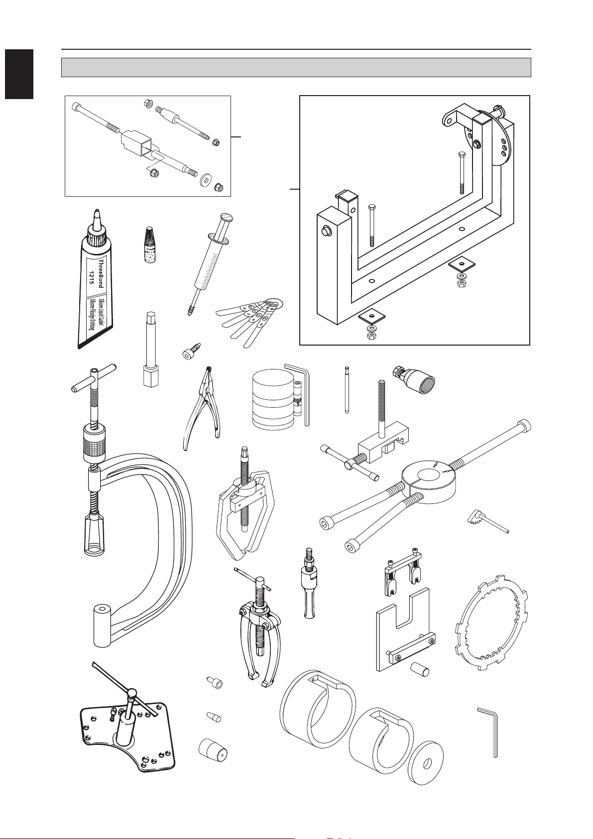
SPECIAL TOOLS - ENGINE
2
1
3
4
22
23
6
7
8
9
10
11
12
13
14
15
16
17
18
20
19
5
21
24
25
26
27
Page 12
GENERAL INFORMATION
A
7
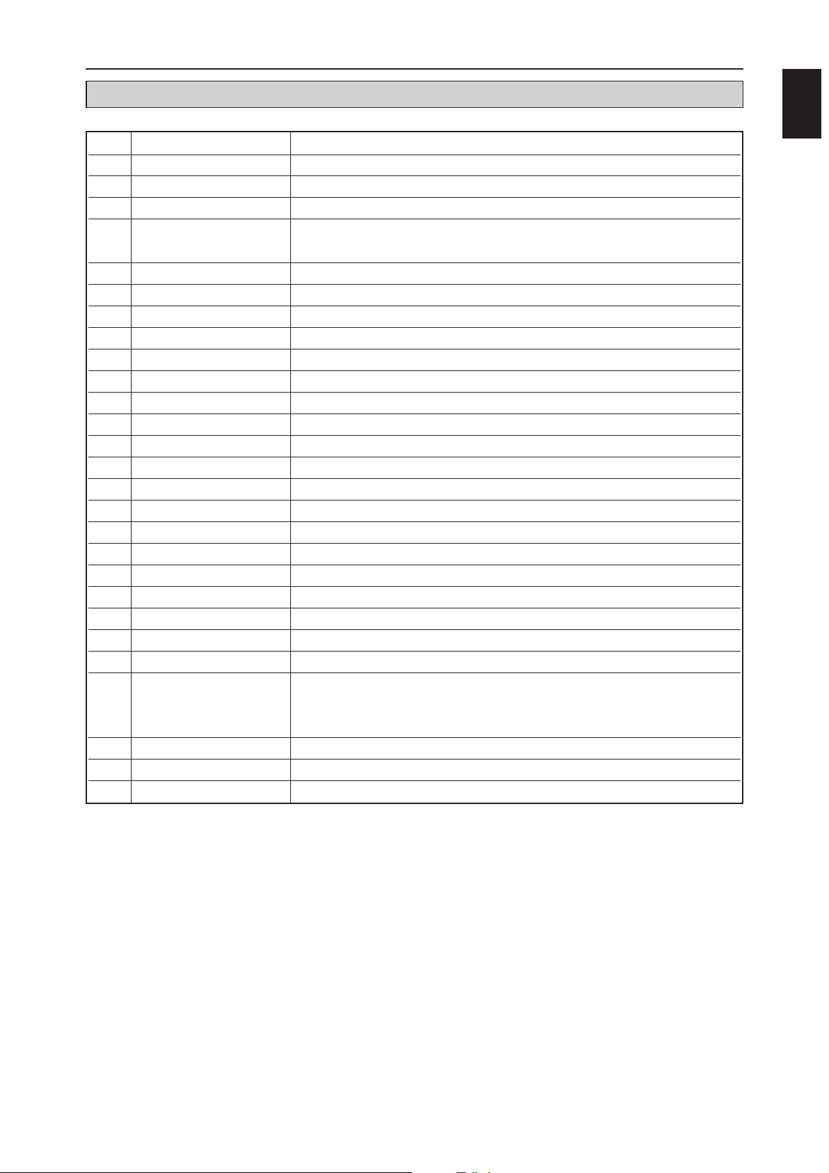
FIG PART NUMBER DESCRIPTION
1 560.12.001.000 Universal engine work stand
2 800.29.002.000 Engine holder for universal engine work stand
3 309098 Silicone three bond sealing compound
46 899 785 Loctite 243 blue 10 ml
800.29.059.000 Loctite 2701 green 10 ml
5 503.29.050.000 Bleeder syringe for hydraulic clutch
6 590.29.041.000 Feeler gauge for valve clearance
7 590.29.072.000 16 mm spark plug wrench
8 580.30.080.000 Locking bolt
9 590.29.019.000 Valve lifter
10 510.12.011.000 Circlip pliers inverted
11 600.29.015.000 Piston ring clamp
12 590.29.026.006 6 mm limit plug gauge for valve guide
13 580.12.009.000 Rotor extractor
14 800.29.030.000 Timing chain riveting tool
15 590.29.033.000 Extractor for timing gear and camshaft bearing
16 584.29.037.037 Mounting tool for bearing inner rings on crankshaft
17 151.12.017.000 Bearing extractor
18 151.12.018.000 12-16 mm insert for bearing extractor
19 800.29.004.000 Gear segment
20 800.29.003.000 Clutch holder
21 800.29.020.000 Housing separating tool
22 800.29.031.000 Protection cover for crankshaft
23 590.29.005.010 Mounting sleeve for the shaft seal ring on the water pump
24 800.29.005.000
Mounting sleeve for the left shaft seal ring on the the crankshaft
800.29.105.000
Mounting sleeve for the right shaft seal ring on the crankshaft
800.29.205.000
Mounting sleeve for the shaft seal ring on the kickstarter shaft
25 800.29.035.000 Pressing tool for conrod bearing (out)
26 800.29.036.000 Pressing tool for conrod bearing (in)
27 800.29.052.000 Safety TORX TX20 for the carburetor potentiometer
SPECIAL TOOLS - ENGINE
Page 13

Page 14
DISMOUNTING AND MOUNTING THE ENGINE
B
1
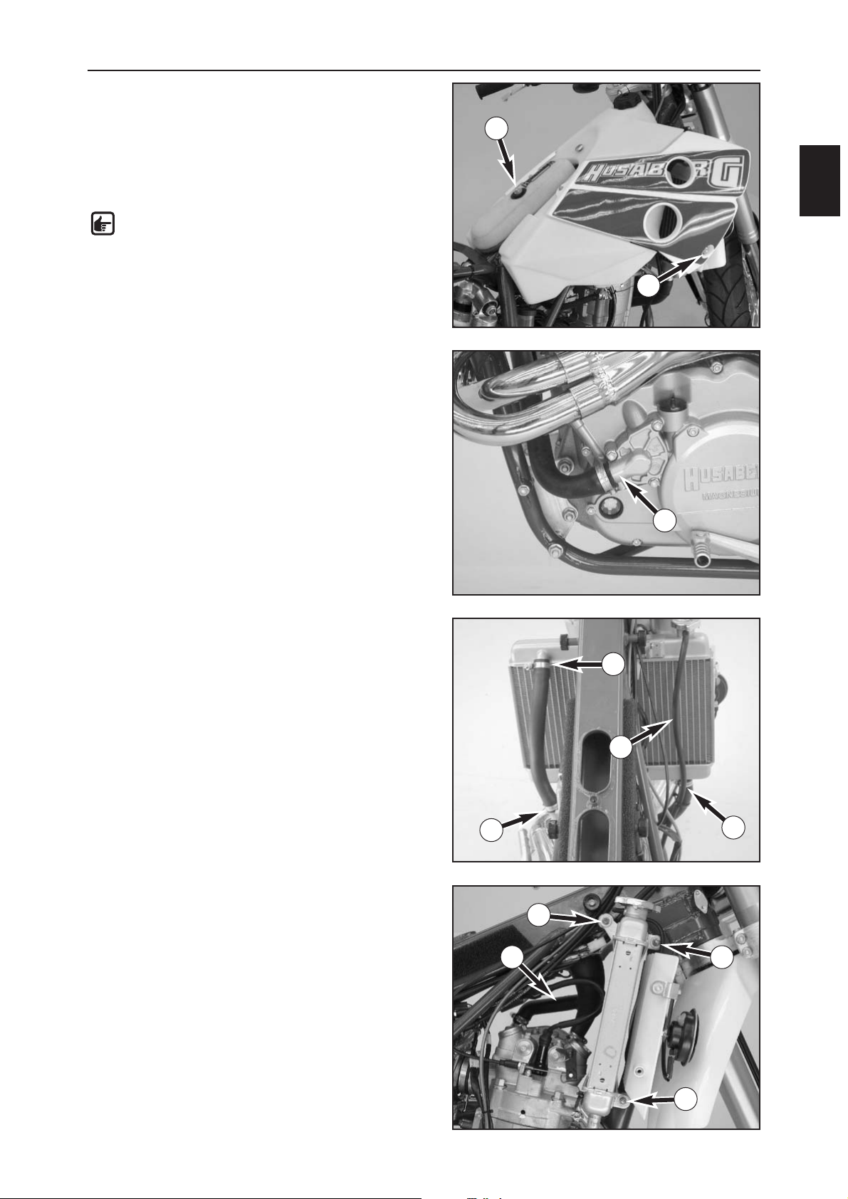
DISMOUNTING THE ENGINE
– Thoroughly clean the motorcycle and jack up on a
sturdy work stand.
– Remove the seat.
– Unscrew the air filter (1).
–Close both fuel taps and disconnect the fuel hoses
– Unscrew both lateral bolts (2) on the spoiler.
NOTE: Hold the retaining sleeve on the radiator
shield with pliers if it turns at the same time.
– Remove the tank with the spoilers.
–Disconnect the ground and positive cable.
– Loosen the hose clamp connecting the water pump
(3), remove the hose and drain the cooling liquid in a
suitable vessel.
– Loosen the hose clamps on the cylinder head (4) and
the radiator (5) and dismount both radiator hoses
together with the overflow hose (6).
–Dismount the engine vent hose (7).
– Remove the three nuts (8) from the radiator mounting
and pull the radiator out of the right side of the frame.
1
5
5
6
2
3
4
8
8
8
7
Page 15
DISMOUNTING AND MOUNTING THE ENGINE
B
2
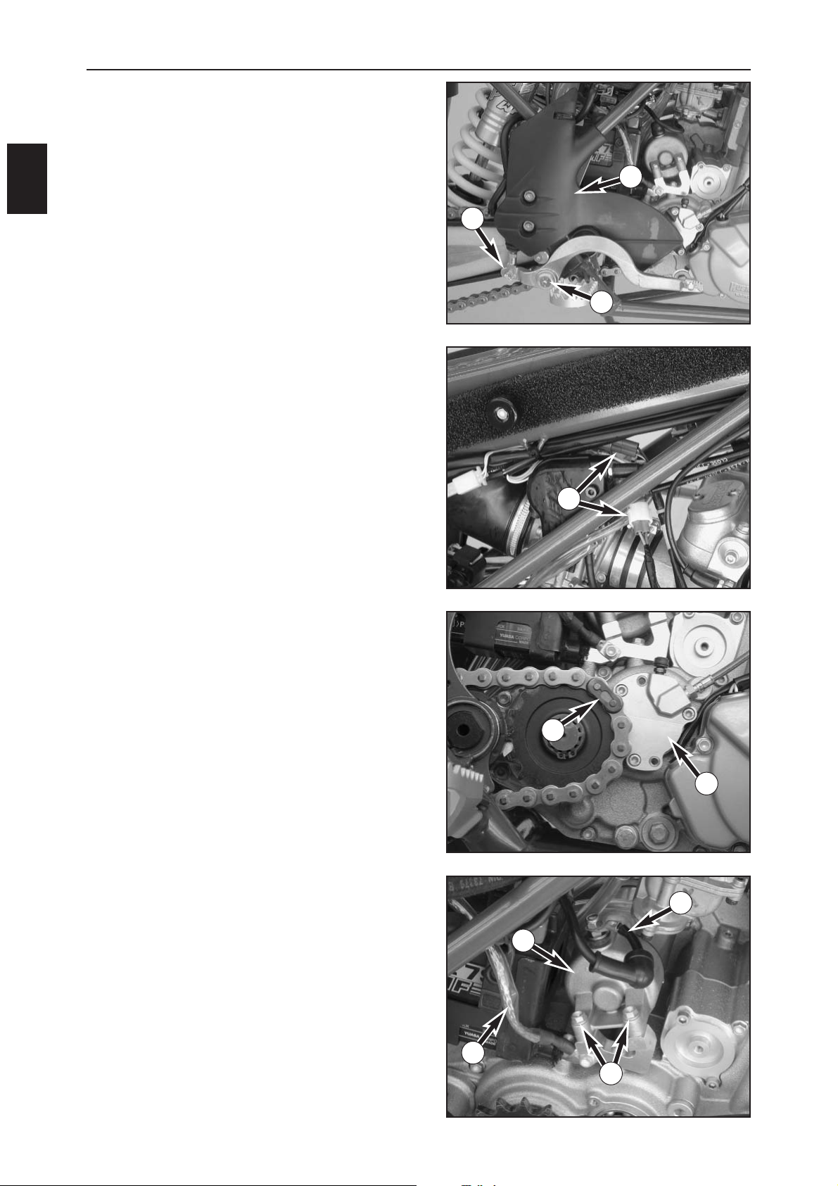
–Dismount the right frame protector (1).
– Unscrew the bearing bolt (2) on the foot brake lever
and tilt the foot brake lever aside.
– Remove the retaining clip from the push rod holder (3),
pull out the bolt and the foot brake lever
–Disconnect the generator and pickup connector (4)
and remove the cable clips from the clutch line.
– Open the chain joint (5), separate the chain and
remove.
– Unscrew the clutch slave cylinder (6) and let it hang to
the side.
–Dismount the positive starter cable (7) from the starter
engine.
– Unscrew the engine ground connection (8).
– Remove both bolts (9) and pull the starter engine (10)
out of the engine case.
1
2
3
5
8
7
9
4
6
10
Page 16
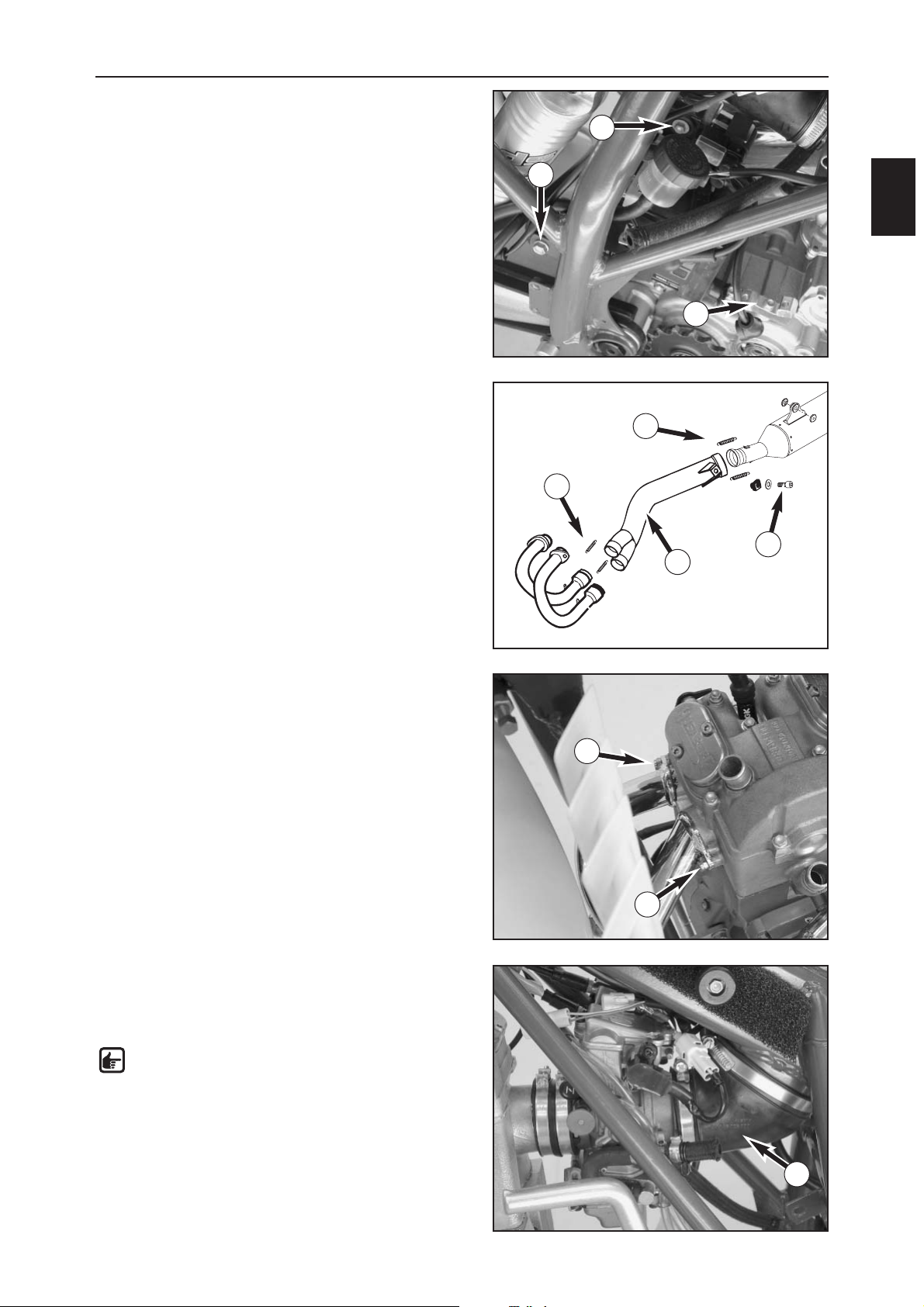
DISMOUNTING AND MOUNTING THE ENGINE
B
3
– Remove the retaining bolt from the starter relay (1),
disconnect the connectors from the starter relay and
lift out the starter relay.
– Unscrew the nut on the chain roller bolt (2).
–Dismount the starter holding bridge (3) and lift the
battery out of the frame together with the battery
case.
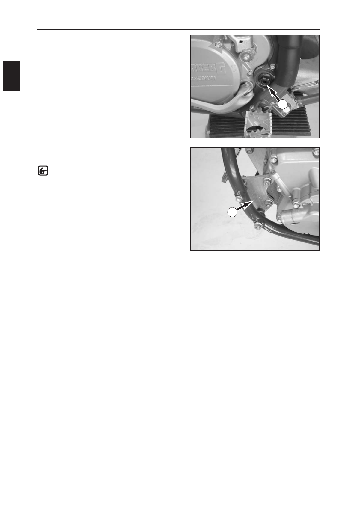
–Use a suitable tool (hooked handle) to detach the front
(4) and rear (5) exhaust springs.
– Remove the exhaust nuts (6) from the cylinder head
and pull both exhaust pipes out of the intermediate
exhaust pipe (7) one at a time.
– Unscrew the bolt (8) and remove the intermediate
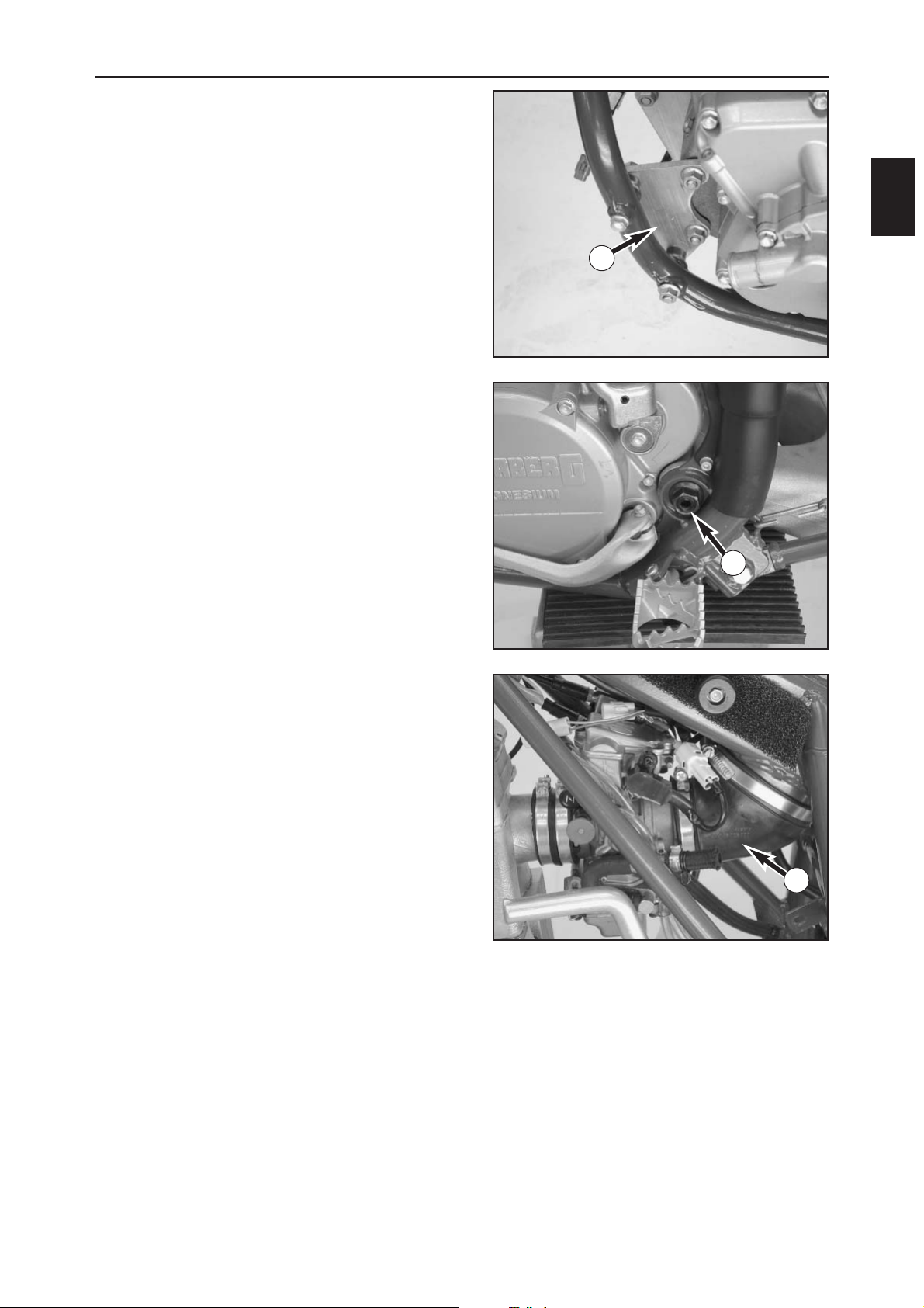
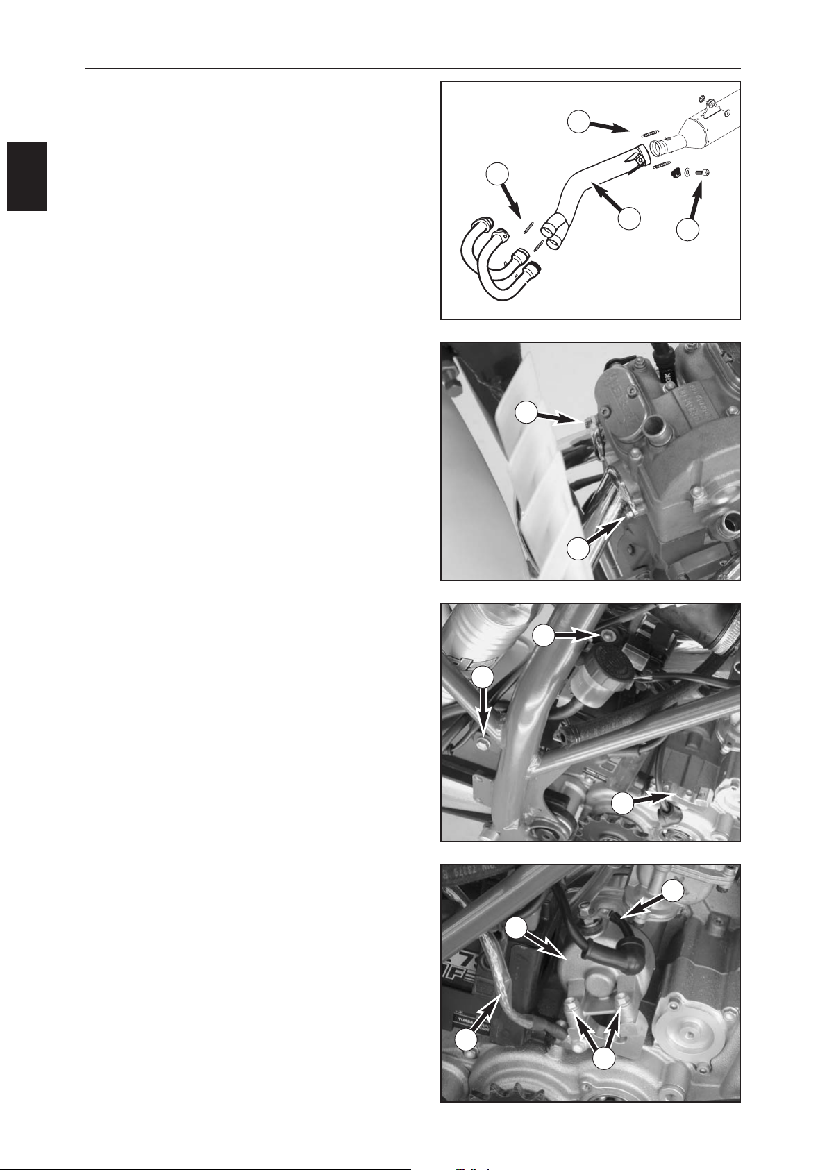
exhaust pipe.
–Loosen the clamps on the carburetor connection boots
and remove the rear carburetor connection boot (9).
– Pull the carburetor out of the front connection boot
and attach to the frame.
NOTE: leave the carburetor in the frame if it
does not need to be serviced.
Move the carburetor vent hoses towards the
rear.
–Disconnect the spark plug connector and separate the
decompression cable from the cylinder head.
1
2
3
4
5
6
6
8
9
7
Page 17
DISMOUNTING AND MOUNTING THE ENGINE
B
4
– Remove the nut from the swing arm pivot (1) and
knock out the swing arm pivot with a suitable pipe.
– Pull the swing arm towards the back and let it rest
against the frame.
– Unscrew the engine mounting plantes (2) and remove
the bolts.
NOTE: hold the engine to prevent it from tilting
out of the frame.
–Lift the engine and lift out of the frame towards the
left.
1
2
Page 18
DISMOUNTING AND MOUNTING THE ENGINE
B
5
MOUNTING THE ENGINE
–Lift the engine into the frame, position the engine
mounting plates (1), insert the bolts and screw on the
nuts but do not tighten yet.
– Position the swing arm and push in the swing arm
pivot (2) from the right until it touches the engine.
– Lift the engine until the swing arm pivot can be
pushed through the engine case, gently tapping with a
plastic hammer if necessary.
– Screw the nut on the swing arm pivot and tighten to
100 Nm.
–Tighten the nuts on the engine mounting plates to
25 Nm.
– Insert the carburetor in the front carburetor connection
boot and tighten the clamps.
–Mount the rear carburetor connection boot (3) and
tighten the clamps
2
1
3
Page 19
DISMOUNTING AND MOUNTING THE ENGINE
B
6
– Mount the intermediate exhaust pipe (1) and tighten
the bolt (2).
–Use a suitable tool (hooked handle) to mount the rear
exhaust springs (3).
–Apply copper paste to the front exhaust pipe at the
connections to the cylinder head and mount.
– Screw on the exhaust nuts (4).
–Mount the front exhaust springs (5).
–Place the battery and battery case in the frame.
– Screw on the starter holding bridge (6).
–Mount the battery case and tighten the nut on the
chain roller bolt (7).
–Mount the starter relay and fix with the bolt (8), attach
the connector.
–Grease the O-ring on the starter engine and mount the
starter engine (9), tighten the bolts (10) to 10 Nm.
– Screw on the engine ground connection (11) and the
positive starter cable (12).
1
2
3
5
4
4
6
7
8
9
10
11
12
Page 20
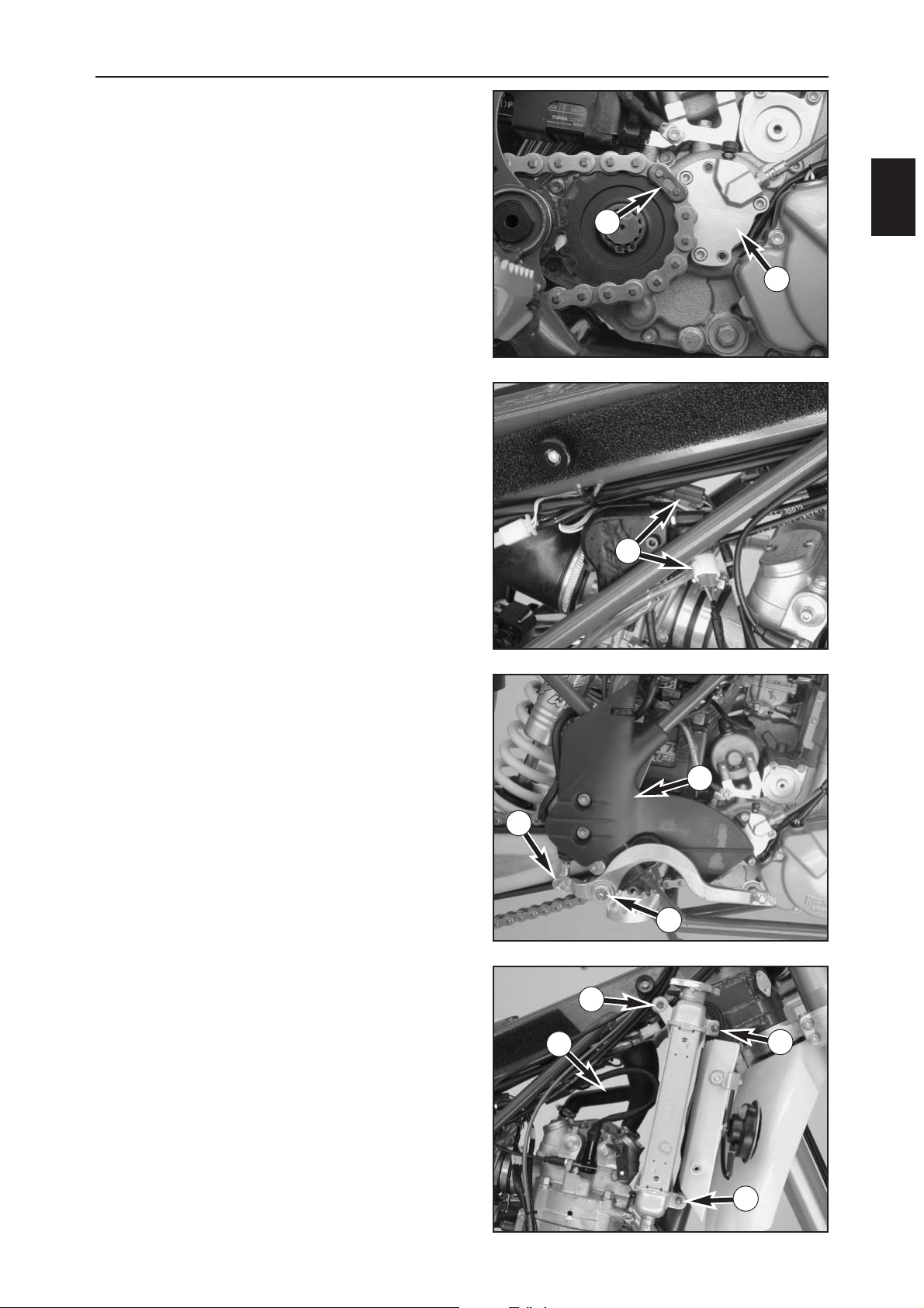
DISMOUNTING AND MOUNTING THE ENGINE
B
7
– Mount the clutch slave cylinder (1) and tighten the
bolts to 6 Nm.
– Position the chain and mount the chain joint (2).
– Connect the generator and pickup connector (3) and
fasten the wiring harness to the clutch line with cable
clips.
– Mount the bolt for the push rod holder (4) and secure
with the retaining clip.
– Position the foot brake lever, secure the bearing bolt
(5) with Loctite 243 and tighten the bearing bolt to
10 Nm.
– Screw on the frame protector (6) and secure with cable
clips.
–Slide the radiator into the frame from the right and
screw on with the 3 nuts (7).
– Mount the engine vent hose (8) and tighten the hose
clamps.
1
2
3
4
5
6
7
7
7
8
Page 21
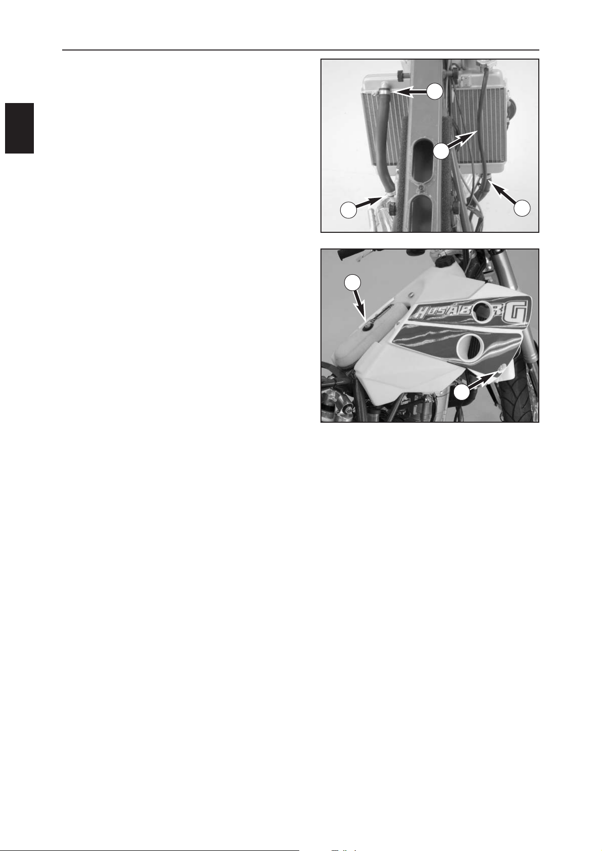
DISMOUNTING AND MOUNTING THE ENGINE
B
8
– Mount both radiator hoses and tighten the hose
clamps (1).
– Connect the overflow hose (2) and attach to the frame
with cable clips.
–Connect the battery cables.
– Mount the tank and tighten the two bolts (4) on the
side of the spoiler.
– Connect both fuel hoses and open the fuel taps.
– Mount the air filter (5) and screw tight.
–Mount the seat.
– Lift the motorcycle off the engine work stand.
–Bleed the cooling system.
– Check the engine oil level.
– Check the oil level and cooling liquid level again after
a short, cautious test ride.
1
1
1
2
3
4
Page 22
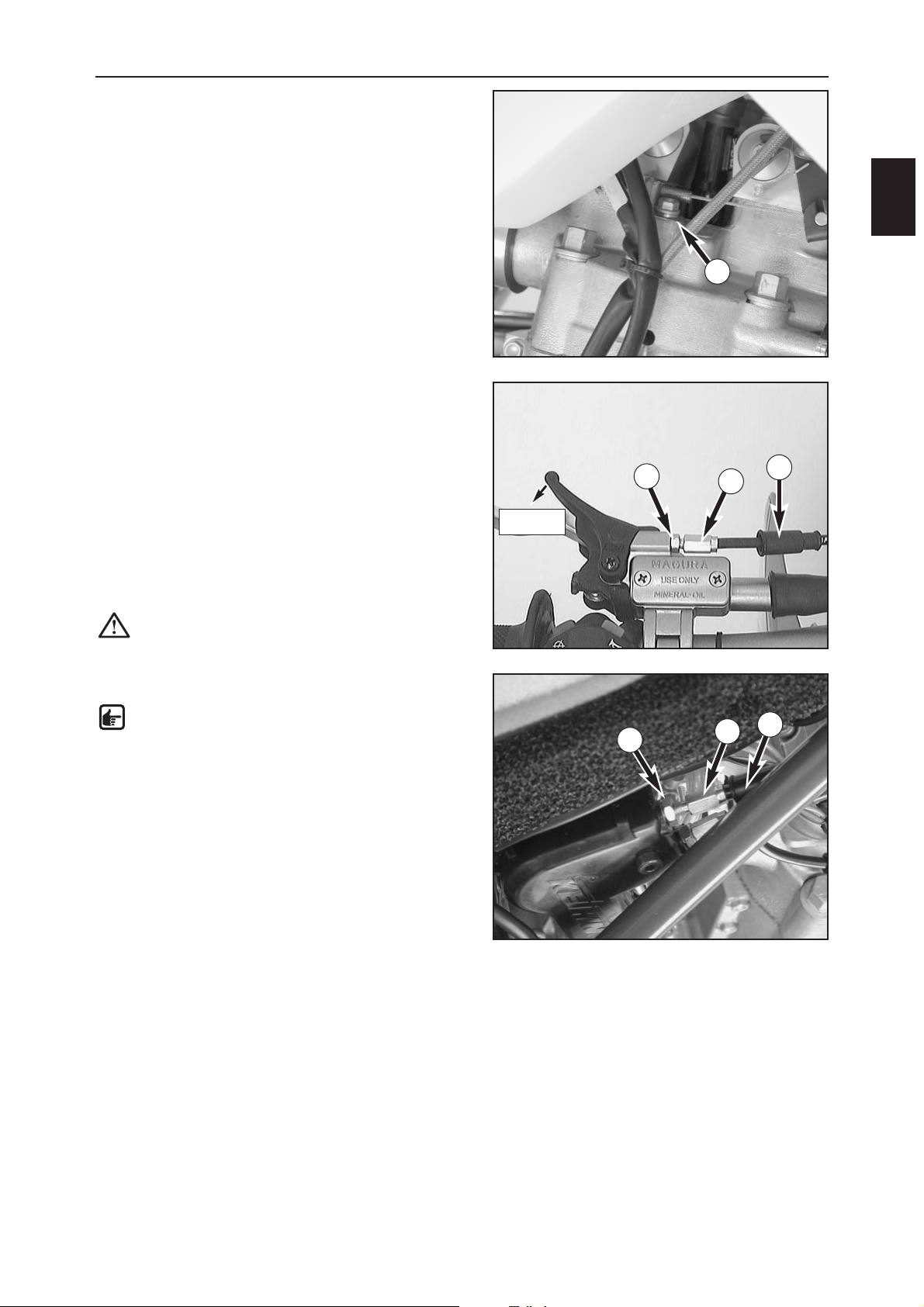
DISMOUNTING AND MOUNTING THE ENGINE
B
9
BLEEDING THE COOLING SYSTEM
– Add cooling liquid until it reaches approx. 10 mm over
the radiator fins.
– Open the bleeder bolt (1) on the cylinder head until
cooling liquid escapes without bubbles, tighten the
bleeder bolt again to 6 Nm.
Check the cooling liquid level again after another short
ride and correct if necessary.
CHECKING THE ADJUSTMENT OF THE
HAND DECOMPRESSION CABLE
–Start the engine and slowly pull the hand
decompression lever at idling speed until you feel the
thumping of the rocker arm on the lever. The free
travel until you feel the thumping should be approx.
10 mm measured at the outer end of the lever. Correct
the free travel if necessary.
–To adjust, push back the protection cover (2), loosen
the counternut (3) and adjust the adjustment screw (4)
as required. Tighten the counternut and slide the
protection cover into place.
CAUTION: no free travel in the decompression
lever will lead to engine damage.
ADJUSTING THE THROTTLE CABLES
NOTE: The throttle grip should always have 3-5
mm free travel. In addition, the idling speed
should not change with the engine running if
the handlebar is turned all the way to the left
or right.
–To adjust the throttle cables, remove the seat and tank
with the spoilers. Push back the protection cover (5),
loosen the counternut (6) and adjust the adjusting
screw (7) as required. Turning the adjusting crew in a
counterclockwise direction will reduce the free travel,
turning it in a clockwise direction will increase the free
travel.
–Tighten the counternut and check the throttle grip for
smooth operation.
– Mount the tank and the seat.
5
6
1
10 mm
2
3
4
7
Page 23

Page 24
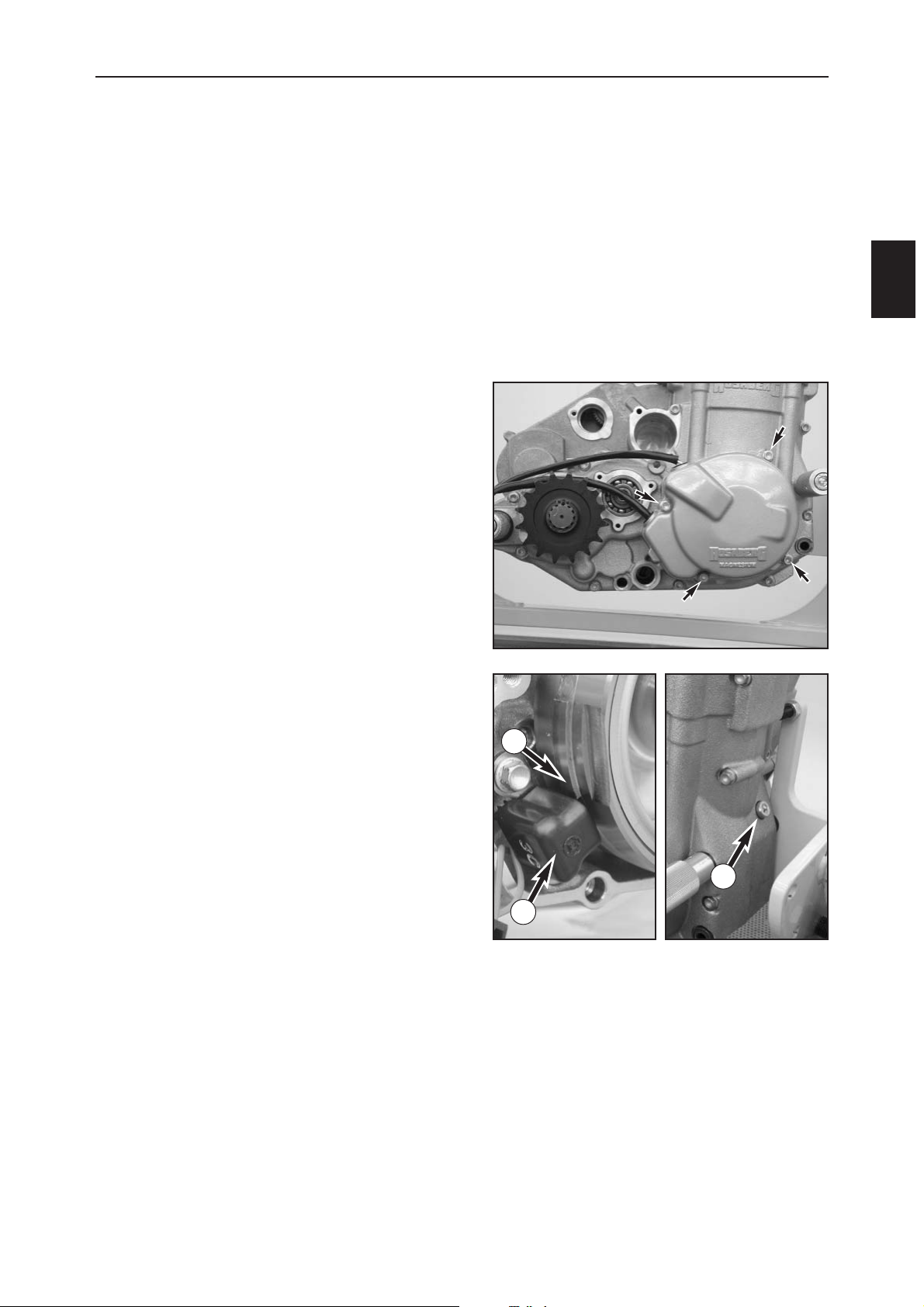
DISASSEMBLING THE ENGINE
C
1
– Thoroughly clean the outside of the engine and clamp
on a universal engine work stand.
– Drain the engine oil, remove the oil filter and the oil
screen (see Chapter A).
– Remove the kickstarter and the shift lever.
– Remove the circlip from the engine sprocket with
suitable pliers, pull the engine sprocket off the shaft.
–Remove the 4 bolts from the generator cover and
remove the generator cover.
– Pull both dowels from the housing and discard the
gasket.
– Unscrew the spark plug with the spark plug wrench
590.29.072.000.
LOCKING THE ENGINE
–Turn the crankshaft in a counterclockwise direction
until the pickup sensor (1) is aligned with the edge of
the shim (2) welded onto the rotor.
– Remove the plug and the copper gasket and screw in
the locking bolt (3) 580.30.080.000 by hand, turning
the crankshaft back and forth to allow the locking bolt
to engage in the recess in the crankshaft
2
3
1
Page 25
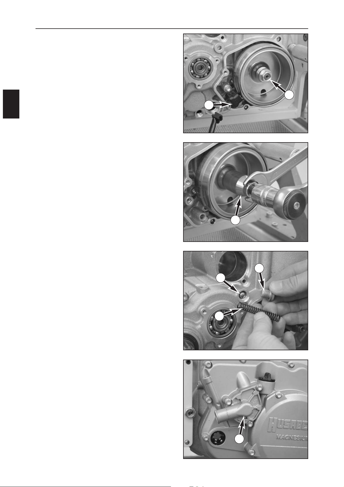
DISASSEMBLING THE ENGINE
C
2
REMOVING THE ROTOR
– Remove the pickup sensor (1).
– Loosen the rotor nut (2) (17 mm – LH thread!) and
remove together with the corrugated washer.
– Screw the extractor 580.12.009.000 (3) to the rotor,
hold the extractor while you screw in the extractor bolt
until the rotor is released from the crankshaft. Remove
the rotor, unscrew the extractor from the rotor.
DISMOUNTING THE PRESSURE RELIEF
VALVE
– Unscrew the plug (4) on the pressure relief valve
together with the copper washer, pull the spring (5)
out of the hole and remove the ball (6) from the
engine case with a magnet or by tilting the engine.
– Remove the water pump cover (7), discard the gasket.
1
2
3
6
5
4
7
Page 26
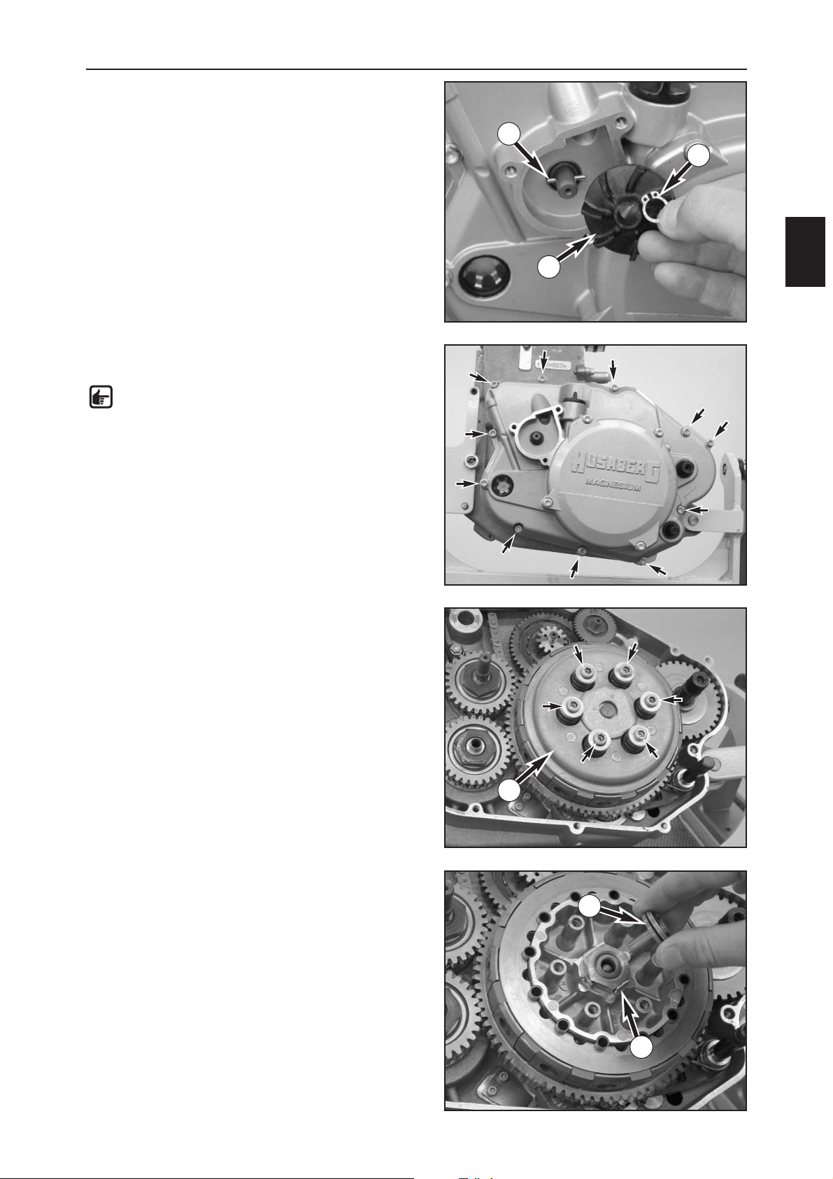
DISASSEMBLING THE ENGINE
C
3
– Remove the circlip (1) from the water pump shaft.
– Carefully pull out the water pump wheel (2) with pliers
and remove the pin (3) from the shaft.
– Remove all of the bolts in the clutch cover and remove
the clutch cover.
NOTE: the outer cover does not need to be
removed separately.
–Discard the gasket and the O-ring in the water duct,
pull the dowels out of the housing.
REMOVING THE CLUTCH
– Loosen the clutch bolts crosswise to prevent the clutch
disks from jamming. Remove the pressure cap (4)
together with the bolts, spring retainer and clutch
springs.
– Remove the pressure piece (5) and the push rod.
– Remove all of the clutch disks from the outer clutch
hub together.
– Remove the clutch sleeves from the inner clutch hub.
– Bend up the lock washer (6) for the clutch nut.
1
2
3
4
5
6
Page 27
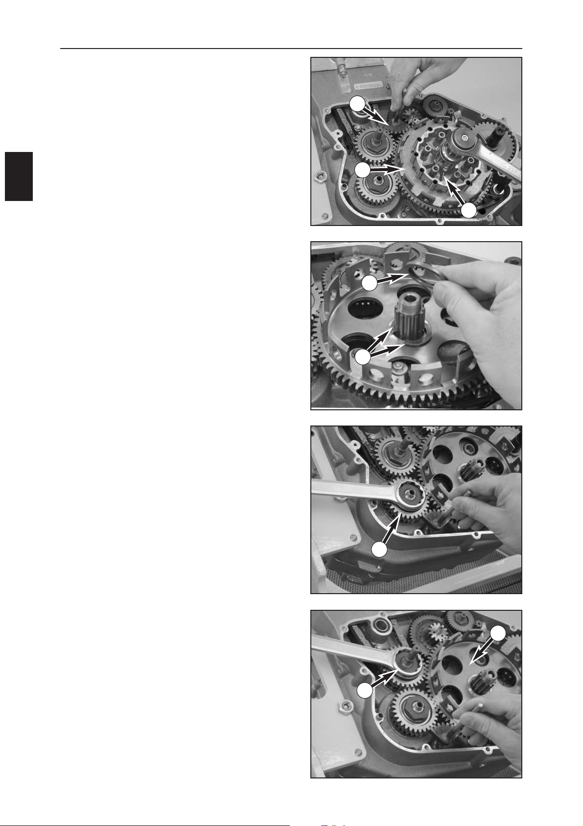
DISASSEMBLING THE ENGINE
C
4
REMOVING THE INNER CLUTCH HUB
– Unscrew the locking bolt.
– Insert the clutch holder (1) 800.29.003.000 in the outer
clutch hub with at least 6 clutch sleeves, lock the outer
clutch hub with the gear wheel segment (2)
(800.29.004.000) as shown in the photo and loosen the
nut (27 mm).
– Remove the clutch holder, the nut and lock washer and
the inner clutch hub (3).
– Remove the stepped disk (4) and both half disks (5).
REMOVING THE PRIMARY PINION AND
IDLER SHAFT GEAR
– Lock the primary pinion (6) with the special tool
800.29.004.000 (gear segment) as shown in the photo
and unscrew the nut (30 mm) on the primary pinion.
– Lock the idler shaft (7) with the special tool
800.29.004.000 (gear segment) as shown in the photo
and unscrew the nut (30 mm) on the idler shaft.
– Remove the outer clutch hub (8) with the two needle
bearings and the washer located below.
1
2
4
7
3
5
6
8
Page 28
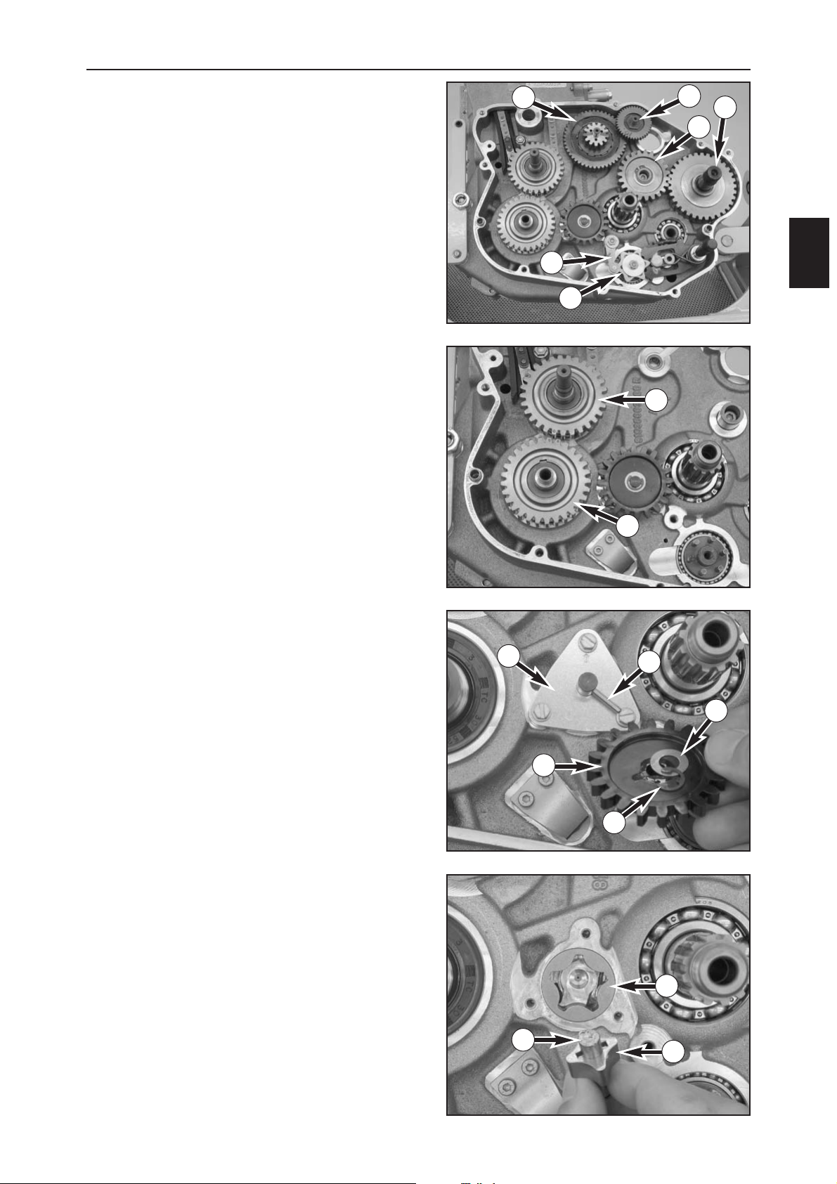
DISASSEMBLING THE ENGINE
C
5
– Pull the idler (1) and the freewheel (2) from the engine
case (only applies to starter models).
– Remove the circlip on the kickstarter idler gear (3) and
pull the kickstarter idler gear with the upper and lower
disk and the needle bearing off of the bearing bolt.
– Forcefully pull the kickstarter shaft (4) out of the
housing and dismount together with the gear wheel,
the bearing and the spring.
– Loosen the bolts on the shift locating drum (5) and on
the shift lock (6).
–Dismount the shift locating drum with the upper and
lower disk as well as the bolt.
– Relieve the shift lock spring and dismount the shift
locking lever together with the bolt, sleeve and spring.
–Dismount the shift shaft.
– Remove the primary pinion (7) and the gear on the
idler shaft (8), pry both woodruff keys out of the shaft
grooves.
REMOVING THE OIL PUMP
–Pry the circlip (9) on the oil pump gear (10) from the
shaft, removing the washer (11), oil pump gear and pin
(12).
– Loosen the three screws and remove the oil pump
cover (13).
–Dismount the oil pump shaft (14) together with the
inner rotor (15), pin and outer rotor (16).
1
2
3
4
5
6
7
8
9
10
11
12
13
14
15
16
Page 29
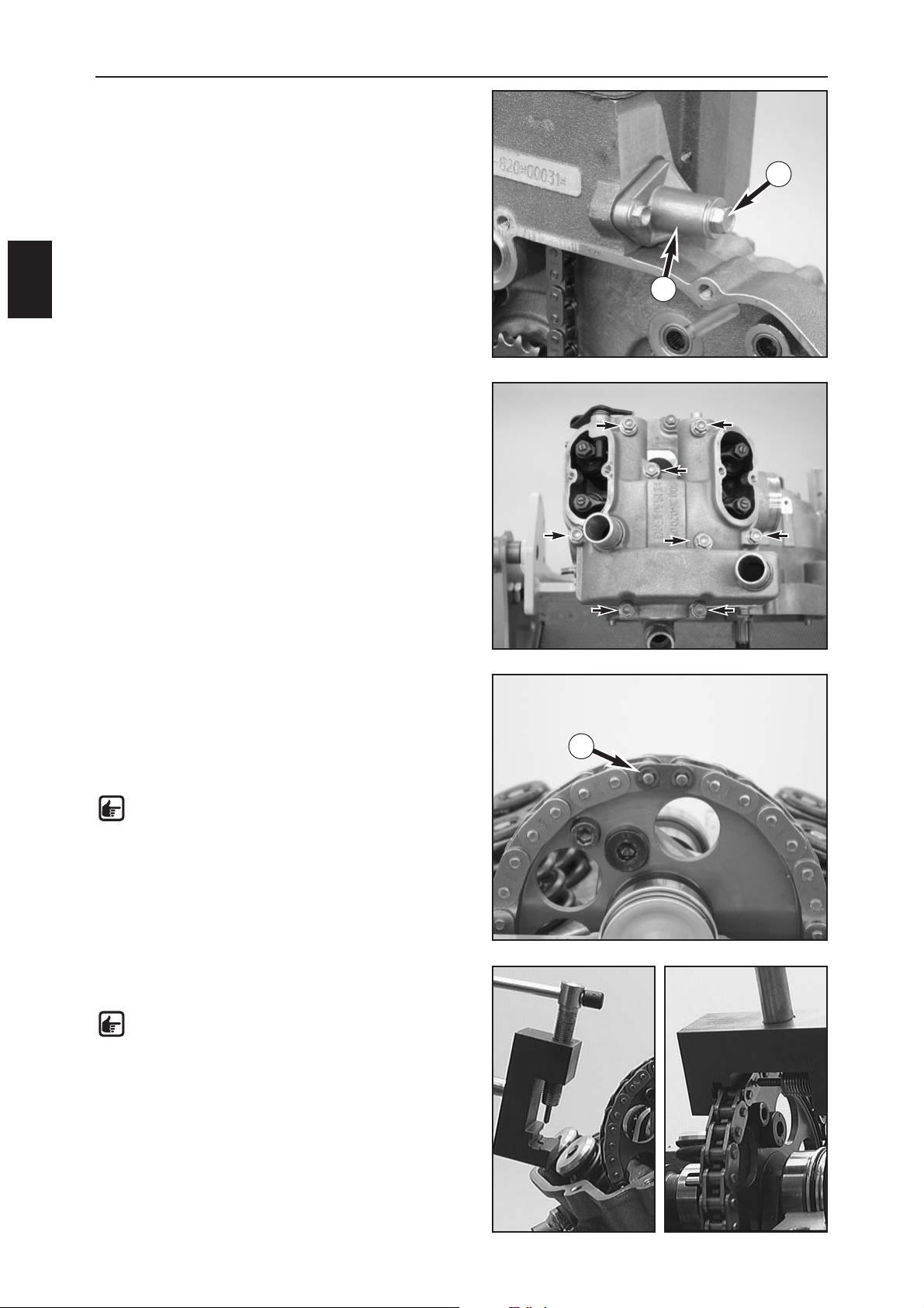
DISASSEMBLING THE ENGINE
C
6
REMOVING THE CHAIN TENSIONER
– Remove the bolt (1) together with the seal ring and
chain tensioning spring.
– Unscrew the chain tensioner (2).
– Remove both valve covers, discarding the gaskets.
– Loosen the bolts on the cylinder head top section,
carefully tap on the side with a plastic hammer and
remove the cylinder head top section.
SEPARATING THE TIMING CHAIN
–Turn the camshaft until the chain joint (3) is on top and
can be easily opened.
– Remove the chain joint retainer, pull off the chain
shims and remove the chain joint.
– Pull the chain out of the chain tunnel.
NOTE: there are 2 types of chain joint retainers,
each has a different shape.
If the timing chain does not have a chain joint,
use timing chain separating tool
800.29.030.000 to open the chain.
– Apply the timing chain separating tool and turn the
spindle to open the timing chain.
NOTE: the timing chain can be separated at any
point. The pressed open chain link must be
replaced and can be replaced by a chain link
with a chain joint.
–Remove the camshaft and cap from the cylinder head.
1
2
3
Page 30
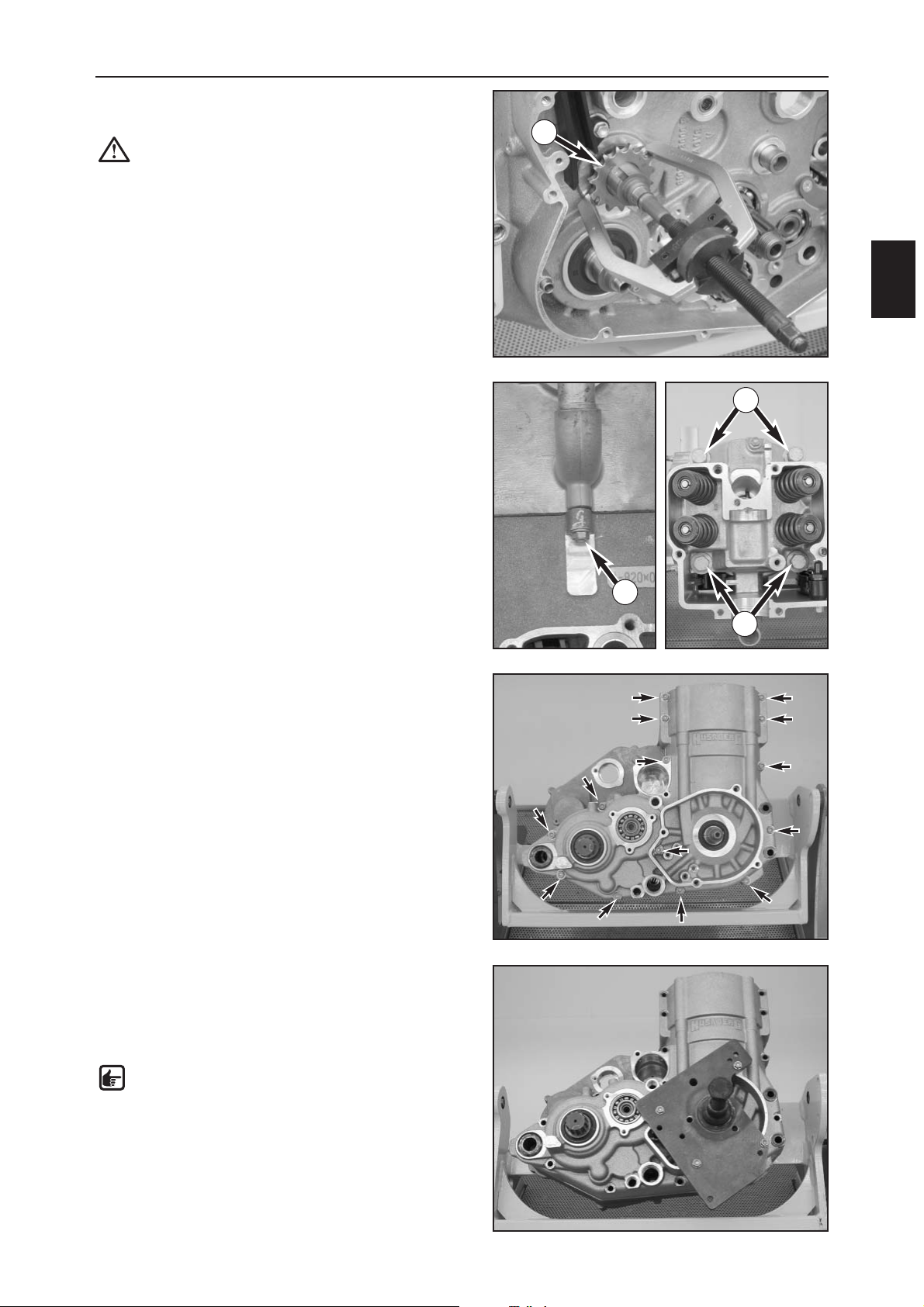
DISASSEMBLING THE ENGINE
C
7
– Pull the rear sprocket (1) off of the idler shaft with the
extractor 590.29.033.000.
CAUTION: Hold the extractor and do not let it
touch the chain guide.
–Pry the woodruff key from the shaft.
REMOVING THE CYLINDER HEAD
– Remove the bolt on the left side (2).
– Loosen the 4 cylinder head bolts (3) crosswise and
remove together with the washers.
–Lift off the cylinder head with the sleeves and gasket,
discarding the gasket.
SEPARATING THE HOUSING HALVES
– Remove all of the housing bolts from the right housing
half.
– Screw the special tool 800.29.020.000 onto the right
housing half and separate the two housing halves by
turning in the spindle. Gently tap on the side of the
housing with a plastic hammer to prevent the housing
halves from being distorted.
NOTE: do not use a screwdriver or similar tool
to pry the housing halves apart since this will
damage the sealing areas.
– Remove the dowels.
1
2
3
3
Page 31
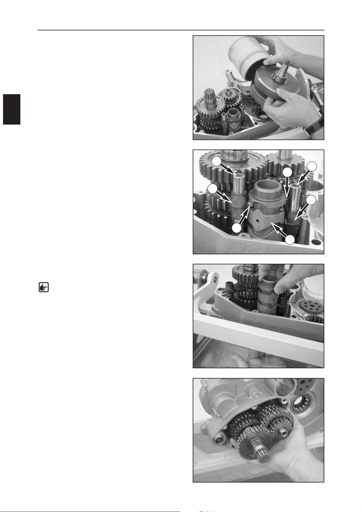
DISASSEMBLING THE ENGINE
C
8
REMOVING THE CRANKSHAFT
–Lift the crankshaft out of the housing together with the
conrod, piston and cylinder liner, tapping gently on
the rear crankshaft with a plastic hammer if necessary.
REMOVING THE TRANSMISSION
– Pull both shift rails (1) out of the housing.
–Tilt the shift forks (2) aside, the shift rolls (3) usually
remain in the shift drum (4) and should be removed
with a magnet.
–Press the shift drum up from below while turning it
until it can be removed from the housing.
NOTE: if you do not turn the shift drum, the
circlip will get caught on the first gear idler.
– Remove the shift forks from the shift grooves.
– Set the engine case in an upright position (installation
position) and simultaneously pull out both transmission
shafts, gently tapping on the back of the main shaft
with a plastic hammer if necessary.
1
1
2
2
3
3
4
Page 32
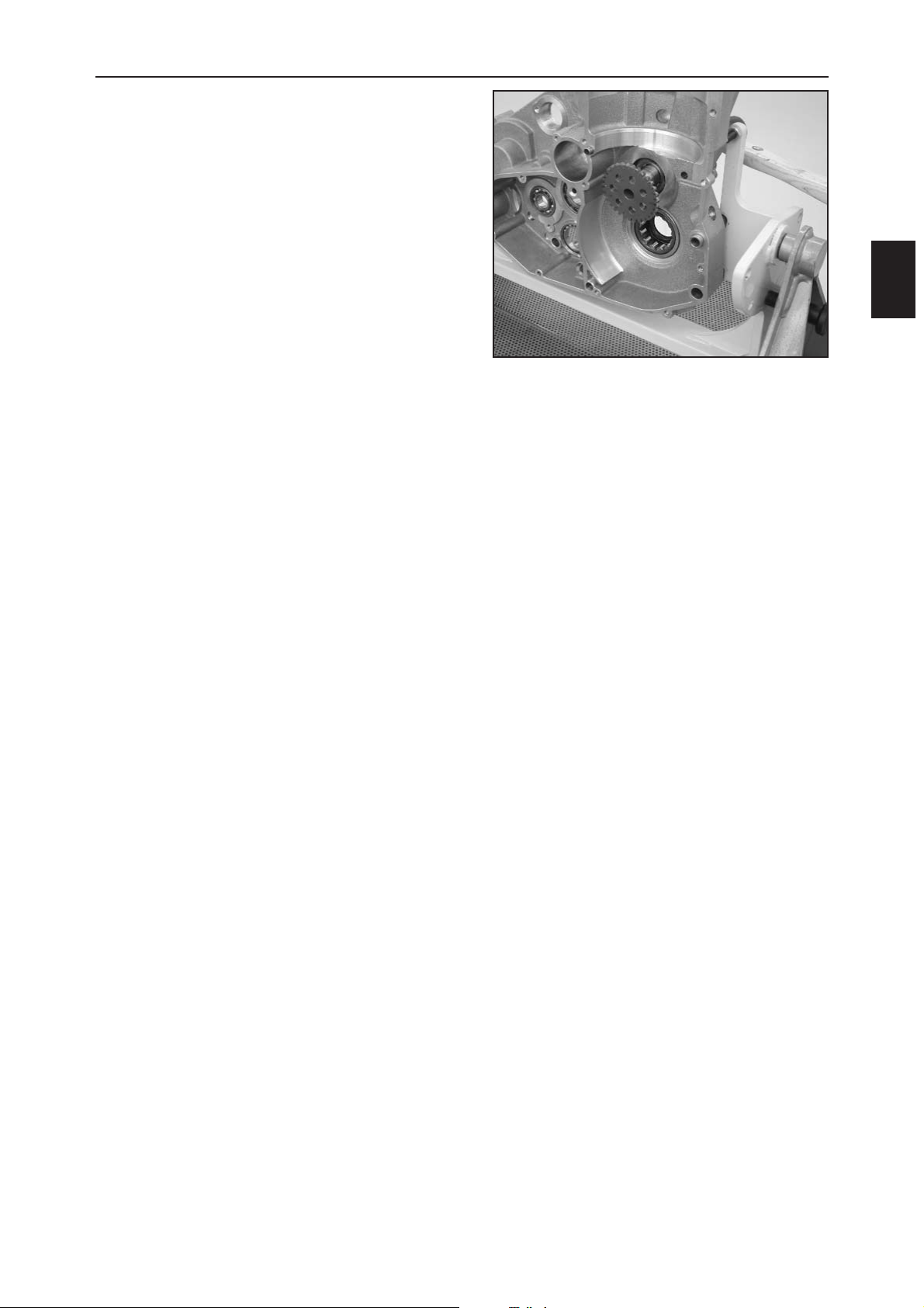
DISASSEMBLING THE ENGINE
C
9
REMOVING THE IDLER SHAFT
– Knock the idler shaft out of the bearing seat from
behind with a plastic hammer.
Page 33

Page 34
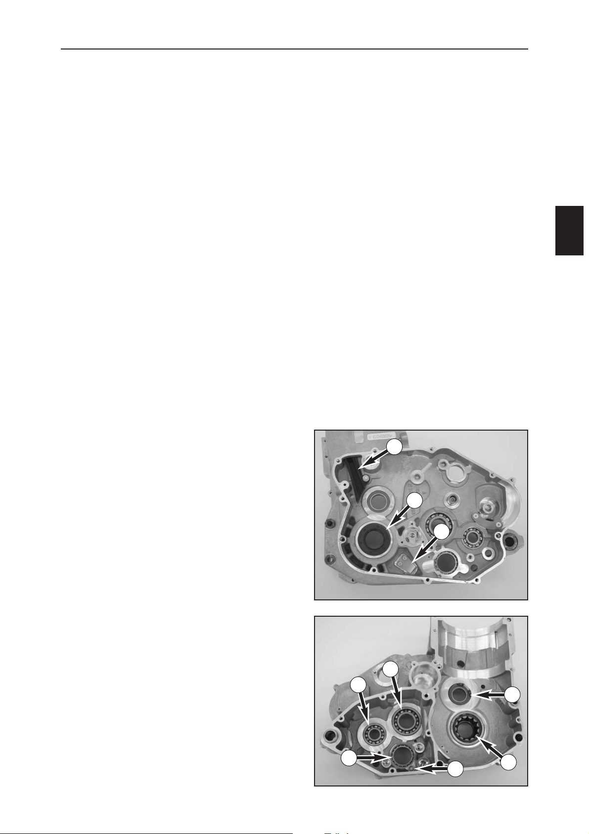
SERVICING THE INDIVIDUAL PARTS
D
1
LEFT HOUSING HALF
– Remove the shaft seal ring (1) from the crankshaft.
–Dismount the chain guide (2).
–Dismount the diaphragm valve (3)
– Remove the circlip (4) from the idler shaft bearing.
– Remove the retaining bolt (5) on the shift drum
bearing.
– Heat the housing half in the oven to approx. 150° C;
the bearings will fall out of the bearing seats
automatically at a housing temperature of approx.
150° C.
Roller bearing for the crankshaft (6)
Press in a new roller bearing from the inside up to the
stop with a suitable mandrel.
Grooved ball bearing for the main shaft (7)
Press in a new grooved ball bearing from the inside up to
the stop.
Grooved ball bearing for the countershaft (8)
Press in a new grooved ball bearing from the inside up to
the stop.
Grooved ball bearing for the shift drum (9)
Press in a new grooved ball bearing from the inside up to
the stop.
The needle bearings in the starter idler and freewheel
usually do not need to be replaced since they do not
wear easily.
IMPORTANT INFORMATION ON WORKING WITH THE ENGINE CASE
Generally, all gaskets, O-rings, crankshaft bearings and the transmission shaft bearings should be replaced
when repairing the engine. In addition, all of the parts need to be cleaned thoroughly, removing any residual
sealant from the sealing areas.
Any bearings removed with an extractor need to be replaced.
Read the following section before you start to work. Establish the assembly order to allow you to insert the
bearings after heating the engine case halves only once.
To press or knock out the bearings, place the respective housing half on a flat surface (first remove the dowels),
placing the housing half on the sealing area to prevent it from being damaged. A wooden panel makes a good
base.
If possible, do not drive in any bearings or shaft seal rings; if you do not have a pressing tool, only drive them in
with a suitable mandrel, using the utmost care. The cold bearings will automatically drop into the bearing seats
at an engine housing temperature of approx. 150° C. If necessary, tap the housing half on an even wooden
surface, if any bearings stay in their seats, press out with a suitable mandrel.
Always press or drive in new bearings at the outer ring of the bearing, otherwise the bearings or their running
surfaces will be damaged.
After the housing half has cooled down, check the bearings for a tight fit; if they are not firmly seated after
cooling down they may turn in the engine case when they warm up. If this happens, the engine case must be
replaced.
1
2
3
4
5
6
7
8
9
Page 35
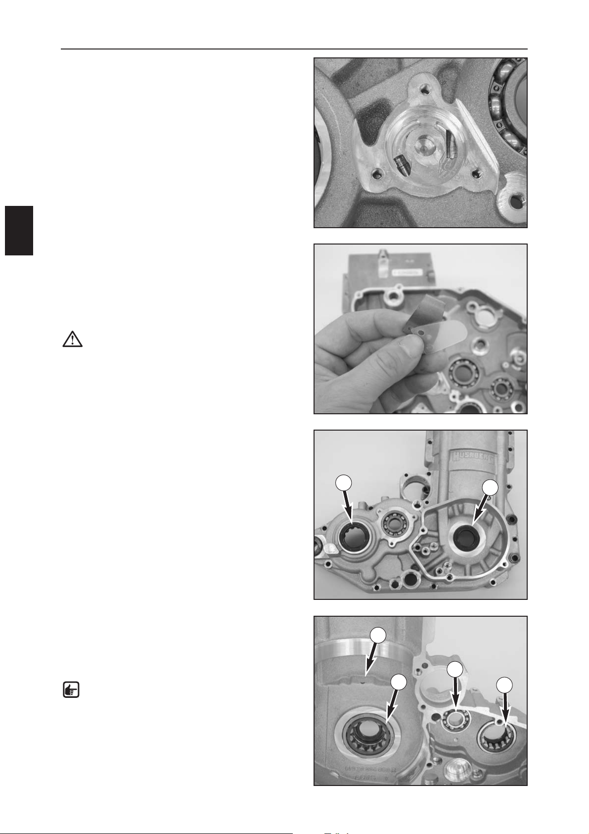
SERVICING THE INDIVIDUAL PARTS
D
2
– Check the oil pump housing for scores and seizing
marks.
– Blow compressed air through all oil ducts and make
sure they are not clogged.
– Check the diaphragm valve for damage, replace the
diaphragm if necessary.
– Remount the diaphragm valve, apply Loctite 243 to
the M4x6 screws and tighten to 1,5 Nm.
–Press the shaft seal ring onto the crankshaft with a
suitable mandrel until flush.
– Mount the chain guide, apply Loctite 243 to the bolt
and tighten to 6 Nm.
CAUTION: make sure the collar on the bolt is
free of screw locking varnish, otherwise the
chain guide will be blocked and may break.
– Mount the circlip on the idler shaft bearing.
– Apply Loctite 243 to the retaining bolt for the shift
drum bearing (M6x8) and tighten to 10 Nm.
RIGHT HOUSING HALF
– Remove the shaft seal rings from the crankshaft (1) and
the countershaft (2).
– Heat the housing half in an oven to approx. 150° C,
the bearings will fall out of the bearing seats
automatically at a housing temperature of approx.
150° C.
Roller bearing for the crankshaft (3)
Press in a new roller bearing from the inside up to the
stop with a suitable mandrel.
Grooved ball bearing for the main shaft (4)
Press in a new grooved ball bearing from the inside until
it fits flush with the housing.
Roller bearing for the countershaft (5)
Press in a new roller bearing from the inside to the stop.
– Blow compressed air through the oil hole (6) and make
sure it is not clogged.
NOTE: engine oil is injected through this hole
to cool and lubricate the pistons and piston pin
bearings.
–Press the shaft seal rings onto the crankshaft and the
countershaft with a suitable mandrel until flush.
1
2
4
5
3
6
Page 36
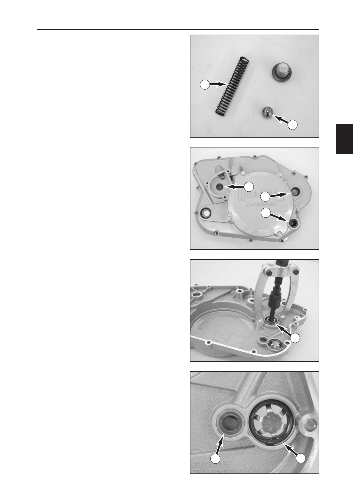
SERVICING THE INDIVIDUAL PARTS
D
3
PRESSURE RELIEF VALVE
– Check the valve ball (1) and the pressure spring (2) for
damage.
CLUTCH COVER
–Pry the shaft seal ring for the shift shaft (3), the
kickstarter shaft (4) and the water pump shaft (5) out of
the clutch cover.
–Press in new shaft seal rings with a suitable mandrel
until flush, making sure the open side of the seal ring
for the water pump faces towards the outside.
– Pull the grooved ball bearing for the water pump (6)
out of the clutch cover with extractor 151.12.017.000
and insert 151.12.018.000.
–Place a wooden panel under the water pump bearing
and press the new bearing in up to the stop with a
suitable mandrel, being careful to press on the outer
ring only.
– Remove the shaft seal ring for the crankshaft (7) and
press in a new seal ring until flush.
– Blow compressed air through the oil duct and make
sure it is not clogged.
–Pry out the ring lock (8) for the oil level viewer out of
the clutch cover.
–Clean the hold and press in a new oil level viewer.
– Mount the ring lock.
The needle bearings in the starter idler and freewheel
usually do not need to be replaced since they do not
wear easily.
3
4
5
6
7
8
1
2
Page 37
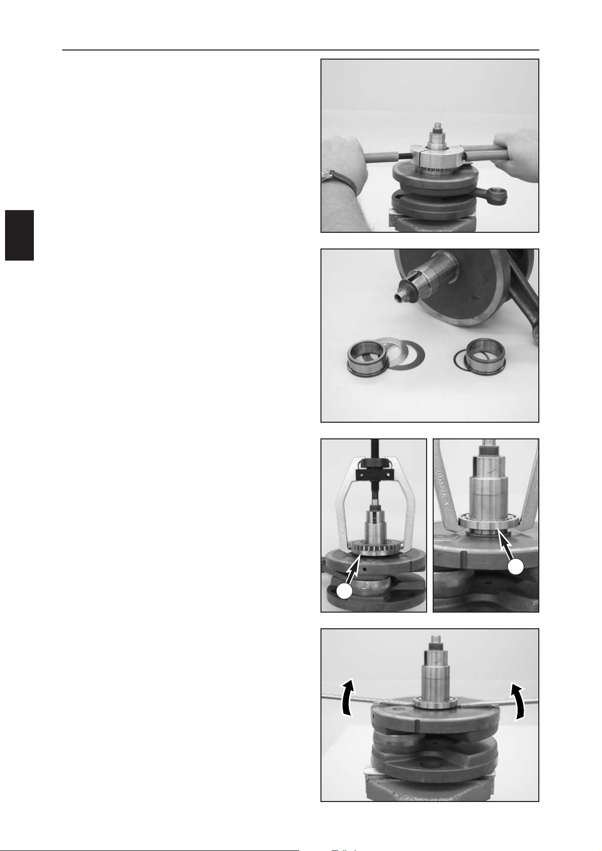
SERVICING THE INDIVIDUAL PARTS
D
4
CRANKSHAFT
– Pull the cylinder liner off of the piston, lift the piston
pin retainer out of the groove and push the piston pin
out of the piston.
–Clamp the crankshaft into the vise – use protective
jaws.
– Heat the special tool 584.29.037.037 to approx.
150° C on a hotplate and immediately push on the
inner ring of the crankshaft bearing. Firmly press the
tool together to obtain a good heat transfer and pull
the inner ring off of the crankshaft with the special
tool.
– Remove the spacing washers from the crankshaft.
– Pull the balance weight (1) off of the crankshaft with
the extractor 590.29.033.000 (use protection cover
800.29.031.000).
– Carefully press the inner bearing (2) upwards with 2
screwdrivers and pull off of the crankshaft using
extractor 590.29.033.000.
1
2
Page 38
SERVICING THE INDIVIDUAL PARTS
D
5
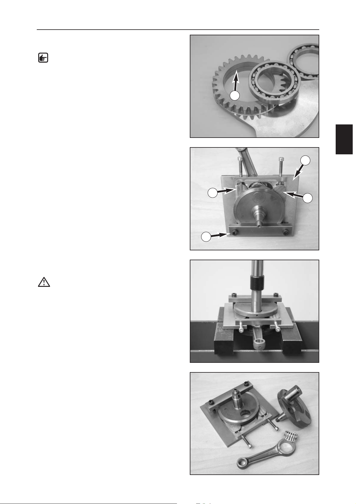
–Press the outer ball bearing out of the balance weight
(on the side with the toothing).
NOTE: the ball bearing cannot be pressed out
through the bottom since it will be blocked by
the ring (1).
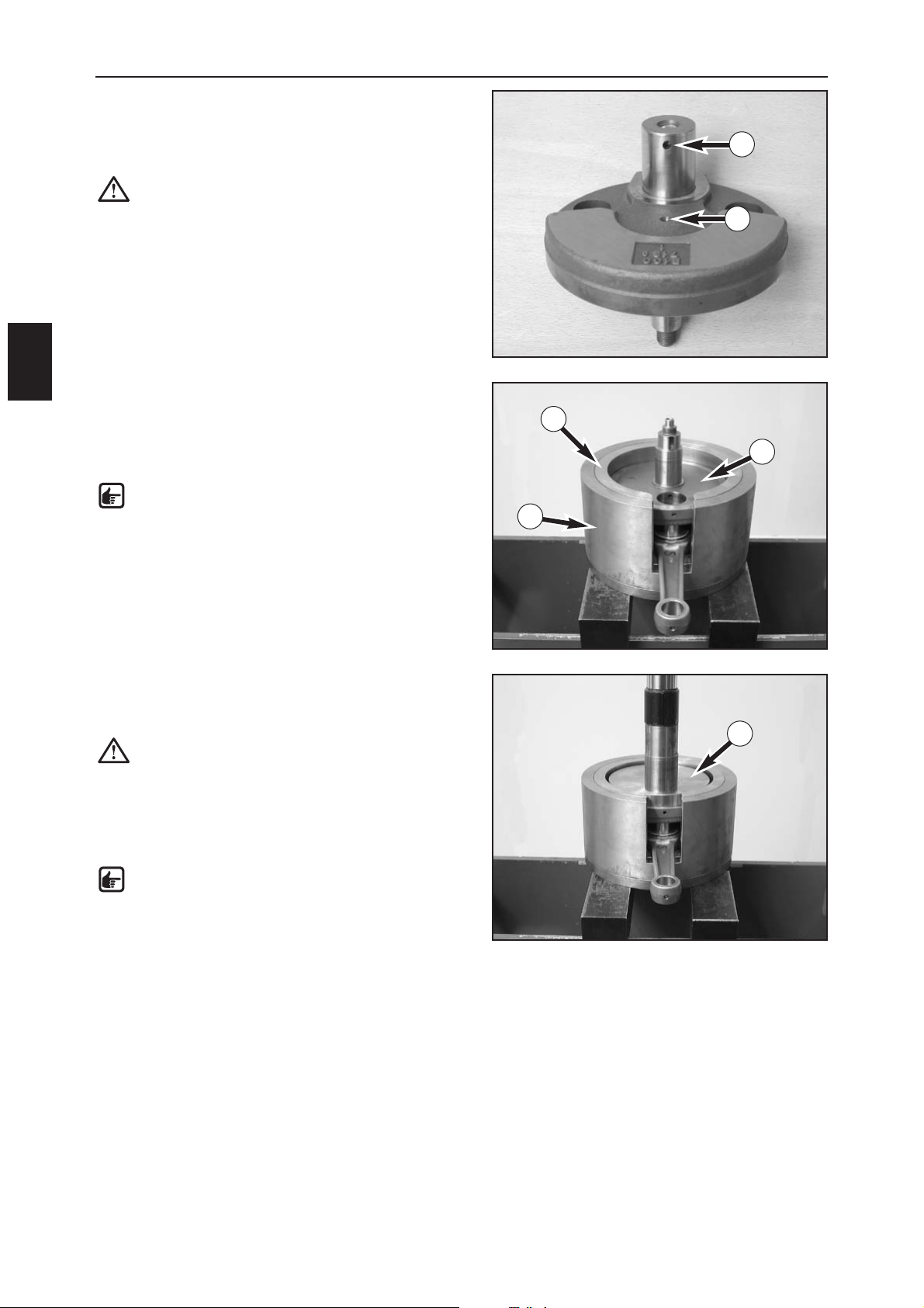
PRESS OUT THE CRANK PIN
–Place the crankshaft and a crankshaft web in the press
out tool 800.29.035.000 (2) as shown in the photo,
being careful not to jam the conrod.
– Move the wedges (3) until the crankshaft lies flat.
–Tighten the screws on the clamping bracket (4).
–Use a hydraulic press to press the crankpin through
with the pressing pin.
CAUTION: hold the lower part of the crankshaft
to keep it from falling down.
–Press the crankpin out of the second crankshaft web in
the same manner.
– Check the crankpin parts, replace any damaged or
worn parts and clean the crankshaft webs.
1
2
3
3
4
Page 39
SERVICING THE INDIVIDUAL PARTS
D
6
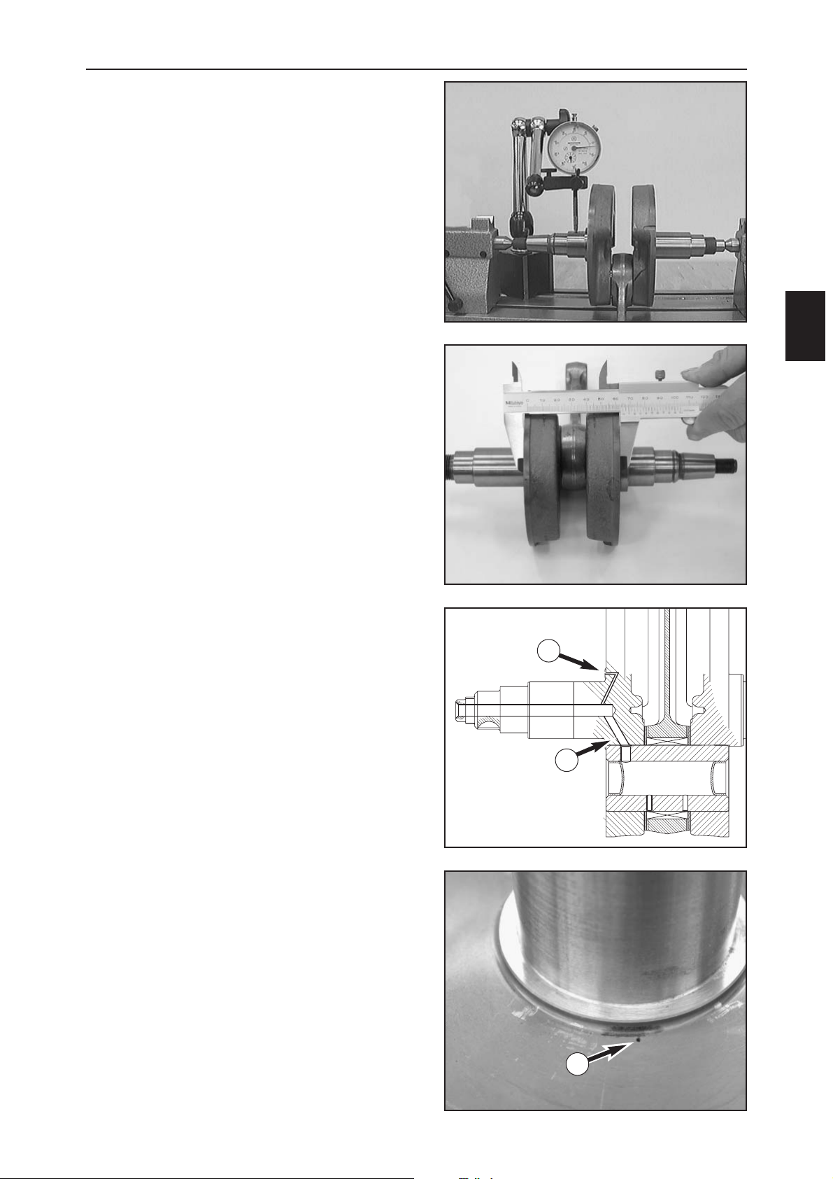
PRESS IN THE CRANK PIN
–Press in the crankpin until flush. The lubrication bore
(1) must point to the exact center (2) of the crankshaft
web, as shown in the photo.
CAUTION: if the lubrication bore is incorrectly
aligned the conrod bearing will not be supplied
with lubricating oil and which will lead to
engine damage.
–Slide the conrod bearing and the conrod on the
crankpin.
– Insert a suitable centering sleeve (3) in the outer part
(4) of the pressing tool 800.29.036.000 and mount the
crankshaft web with the conrod (see photo).
NOTE: Several centering sleeves belong to the
conrod bearing pressing tool 800.29.036.000,
since the outer diameter of the crankshaft webs
can vary depending on the engine
displacement.
–Slide the second crankshaft web (5) in the centering
sleeve with the pressing plate (6) on 800.29.036.000
and press on the crankshaft web.
CAUTION: the pressing plate must be
positioned in the center of the crankshaft web.
To make sure the crankshaft web does not cant,
press onto the crankpin from above.
– Remove the crankshaft from the pressing tool and
check the conrod bearing for smooth operation.
NOTE: after it is pressed in, check the
crankshaft for runout and measure the outer
dimension of the crankshaft webs (see page
D7).
1
2
3
4
5
6
Page 40
D
7
SERVICING THE INDIVIDUAL PARTS
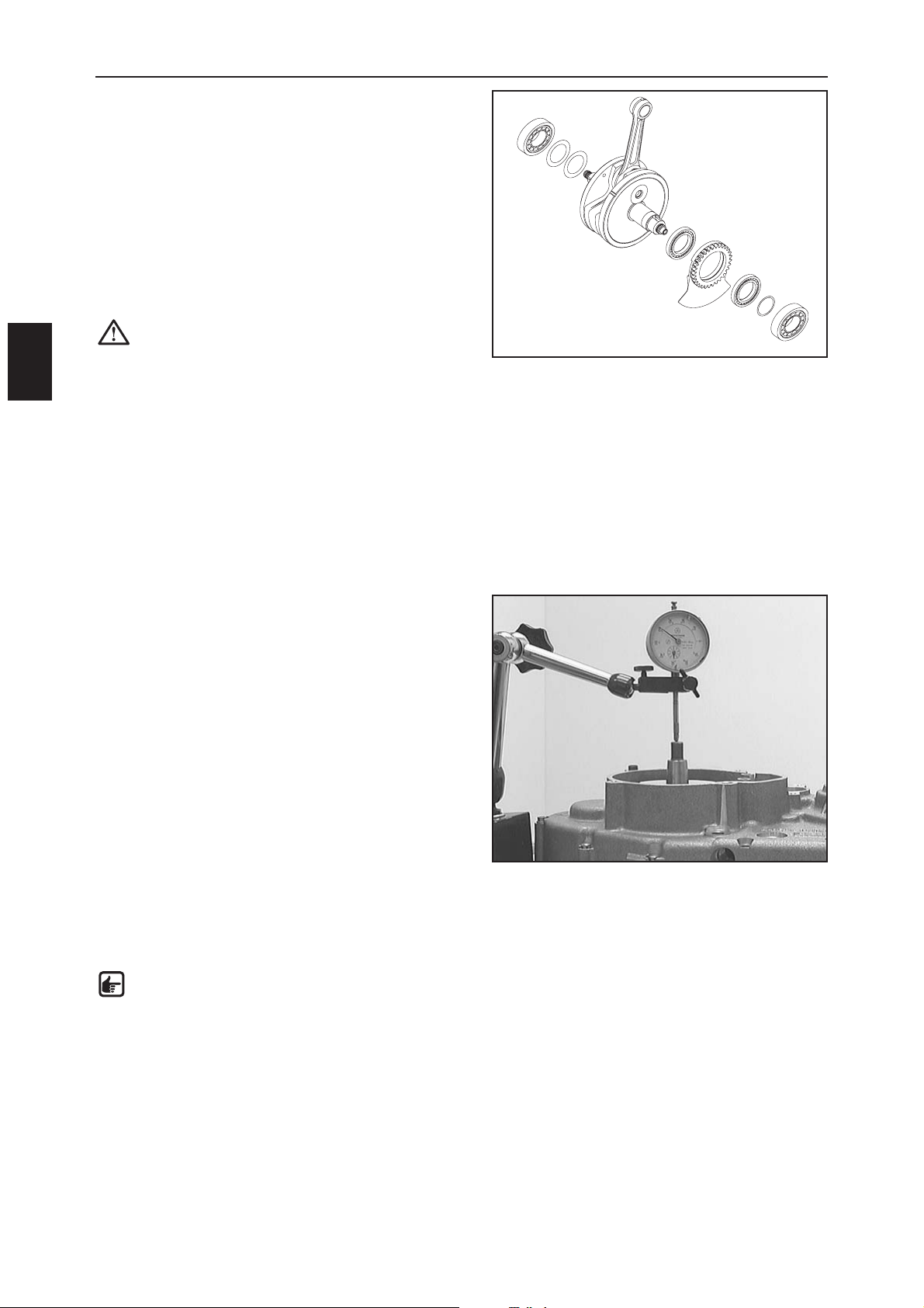
CHECKING THE CRANKSHAFT FOR LATERAL
RUNOUT
–Place the crankshaft on a roller stand or similar support
and use a dial gauge to check the crankshaft for lateral
runout.
Lateral runout: max. 0.12 mm
Check the radial clearance and axial clearance at the
conrod bearing.
Radial clearance: max. 0.05 mm
Axial clearance: max. 1.00 mm
OUTER DIMENSION OF THE CRANKSHAFT
WEB
– Measure the outer dimension of the crankshaft web
using a sliding gauge as shown.
Outer dimension of crankshaft web = 60 mm ± 0.05 mm
–Clean the crankshaft thoroughly, blow compressed air
through the oil holes to the crank pin (1) and to the
ball bearing in the balance weight (2) and make sure
they are not clogged.
1
2
2
Page 41
SERVICING THE INDIVIDUAL PARTS
D
8
–Press the inner ball bearing (1) on the balance weight
(2) onto the crankshaft with a suitable pipe
– Only press on the inner ring. Press on the balance
weight with the outer ball bearing (3) – only press on
the inner ring.
–Slide the spacing washer (4) (0.2 mm) onto the
crankshaft.
– Heat the special tool 584.29.037.037 with the new
bearing inner ring (5) on a hotplate to approx. 150° C
and immediately slide onto the crankshaft (see page D4).
– Strike on the inner ring with a suitable pipe and allow
to cool.
CAUTION: never clamp the crankshaft with the
crankshaft journal and strike on the inner ring
since this will press the crankshaft webs
together and the crankshaft can no longer be
used.
–Turn the crankshaft over and slide both spacing
washers (6) (0.1 and 0.15 mm) onto the crankshaft.
– Mount a new inner ring of the other crankshaft bearing
(7) as described above.
– Measure the axial clearance of the crankshaft after you
replace the inner rings.
BALANCING THE AXIAL CLEARANCE OF
THE CRANKSHAFT
–Place the crankshaft in the left housing half and mount
the right housing half.
– Mount the housing bolts around the crankcase and
tighten.
– Mount the dial gauge support on the engine case and
measure the axial clearance of the crankshaft.
Axial clearance 450: 0,15 - 0,25 mm
Axial clearance 501,550: 0,45 - 0,55 mm
Axial clearance 650: 0,55 - 0,65 mm
– Correct the axial clearance if the measured value does
not correspond to the setpoint value.
–To correct, remove the crankshaft and the inner ring of
the crankshaft bearing (7) and pull off of the crankshaft
with the special tool 584.29.037.037 on the ignition
side. Add or remove compensating disks and remount
the inner ring (see above).
NOTE: Add compensating disks if the axial
clearance is too large. Remove compensating
disks if the axial clearance is too small. Only
add compensating disks on the ignition side.
5
6
7
4
2
3
1
Page 42
SERVICING THE INDIVIDUAL PARTS
D
9
NIKASIL CYLINDER COATING
Nikasil is the brand name for a cylinder coating process
developed by the Mahle piston company. The name is
derived from the two materials used in the process – one
layer of nickel in which the exceptionally hard silicon
carbite is embedded. The major advantages of the
Nikasil coating include its outstanding heat dissipation
and the improved power output, the insignificant wear
and low weight of the cylinder/cylinder liner. It is
inexpensive to repair (replace) a worn coating if the
cylinder barrel is not damaged.
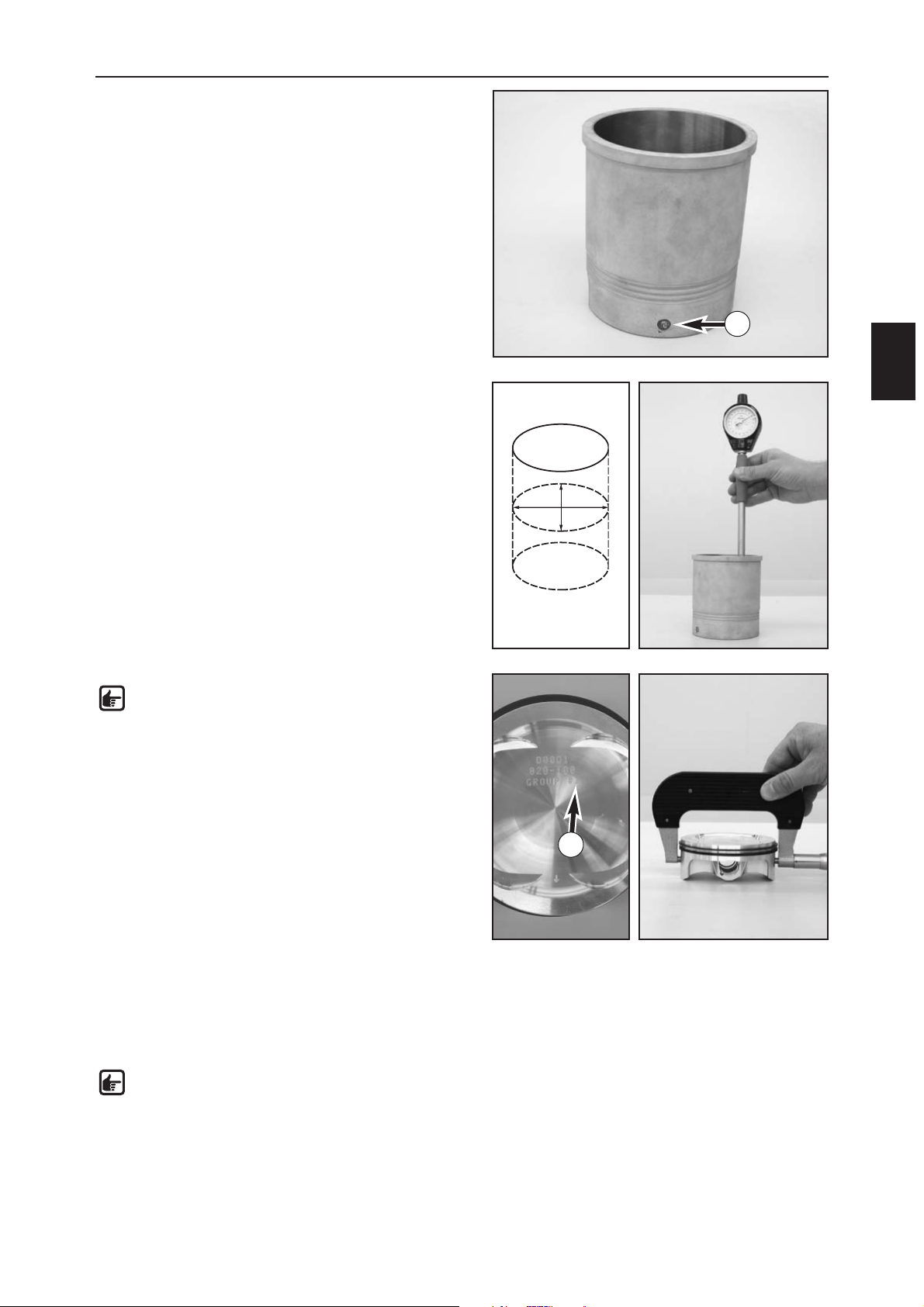
MEASURING THE PISTON AND CYLINDER
LINER, ESTABLISHING THE MOUNTING
CLEARANCE OF THE PISTON
–To establish the wear to the cylinder liner, use a
micrometer to measure the liner in the middle of the
bearing surface.
– Measure the diameter of the cylinder liner in the X and
the Y axis to detect any ovality.
Diameter 450, 550, 650
Cylinder liner size I: 100,000 - 100,012 mm
Cylinder liner size II: 100,013 - 100,025 mm
Diameter 501
Cylinder liner size I: 95,000 - 95,012 mm
Cylinder liner size II: 95,013 - 95,025 mm
NOTE: mark the cylinder liner size (1) on the
side of the cylinder liner, the piston size (2) on
the piston head.
If measured diameter of a size I cylinder liner
falls within the size II tolerance zone, order a
new size II piston.
– The piston is measured at the piston skirt across the
piston pin as shown in the drawing.
– The piston mounting clearance is the difference
between the smallest cylinder liner diameter and the
piston diameter.
Piston mounting clearance 450, 550, 650 uncoated
0,072 - 0,097 mm
Wear limit: 0,12 mm
Piston mounting clearance 450, 550, 650 coated
0,042 - 0,087 mm
Wear limit: 0,12 mm
NOTE: Uncoated pistons have light-colored
metal, coated pistons are dark-colored with
black coating.
Piston mounting clearance 501
Piston size I: 0,040 - 0,080 mm
Piston size II: 0,044 - 0,085 mm
Wear limit: 0,12 mm
1
2
x
y
Page 43
SERVICING THE INDIVIDUAL PARTS
D
10
CHECKING THE PISTON
– Replace the piston if oil consumption is high or the
piston skirt is excessively grooved.
– If the piston is to be remounted:
1. Check the piston bearing surface for damage
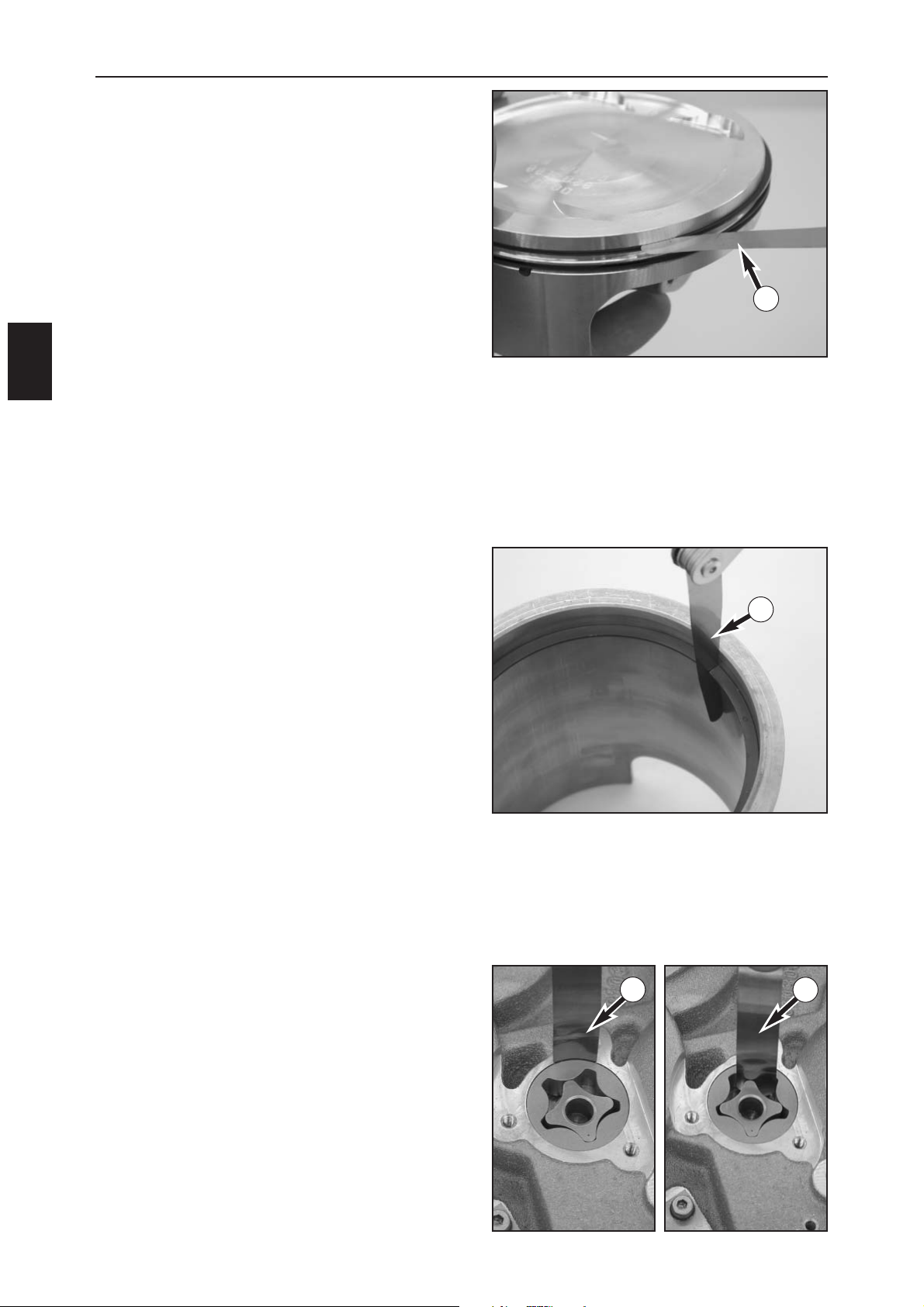
2. Piston ring grooves: use a feeler gauge (A) to measure
the piston ring clearance in the piston ring groove.
Wear limit: 0,15 mm
The piston rings must move freely in the groove. Use
old piston rings or sandpaper (400 grit) to clean the
piston ring grooves.
3. Check the piston rings for damage and end gap.
Mount the oil scraper ring with the "O" mark facing up.
Mount the rectangular ring with the "O" mark facing up.
4. Replace piston pins that are badly discolored or have
visible running marks. Place the piston pin in the
conrod and check for clearance.
CHECKING THE PISTON RING END GAP
– Insert the piston ring in the cylinder and align with the
piston (approx. 10 mm under the upper edge of the
cylinder).
–Use a feeler gauge (A) to measure the end gap.
Compression ring : max. 0.80 mm
Oil scraper ring : max. 1.00 mm
If the end gap is larger than indicated above, check the
cylinder for wear. If the cylinder wear is within the
tolerance limits, replace the piston ring.
CHECKING THE OIL PUMP FOR WEAR
– Insert the inner rotor in the engine case with the mark
facing towards the outside and the outer rotor with the
mark facing towards the inside.
–Use a feeler gauge (A) to measure the wear:
Outer rotor - oil pump housing: max. 0.20 mm
Outer rotor – inner rotor: max. 0.20 mm
A
A
A
A
Page 44
SERVICING THE INDIVIDUAL PARTS
D
11
CYLINDER HEAD TOP SECTION
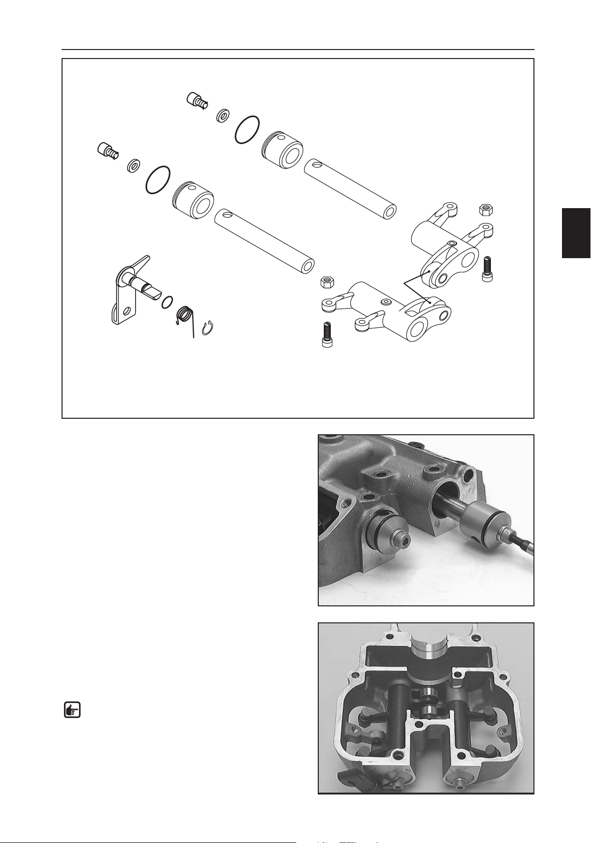
– Remove the circlip (1) and the decompression shaft (2)
out of the bore together with the spring (3).
– Pull the 2 end pieces (4) out of the cylinder head top
section together with the rocker arm shafts (5) + (6).
Remove the rocker arms (7).
–Clean all parts and check for wear.
– Check the rocker arm shafts (5) + (6) for score marks
and smooth operation in the rocker arms (7).
– Check the rocker arm rollers (8) for smooth operation,
replace the rocker arm roller if there is any radial
clearance.
– The seating surfaces of the adjusting screws (9) must fit
flush.
– Check the decompression shaft (2) for smooth
operation and clearance in the bearing bore. Replace
the O-ring (11).
– Replace the O-rings (10).
– Thoroughly oil all parts before reassembling.
– Position the rocker arms in the cylinder head top
section and mount the rocker arm shafts.
NOTE: mount the shorter rocker arm shaft (6) in
the rear.
– Mount the end pieces (4) and turn so that you can
mount the bolts for the cylinder head top section.
–Mount the decompression shaft (2) and pretension the
spring.
2
11
3
1
4
4
5
6
7
7
8
9
9
10
10
Page 45
SERVICING THE INDIVIDUAL PARTS
D
12
CYLINDER HEAD
– Remove the chain tensioning rail.
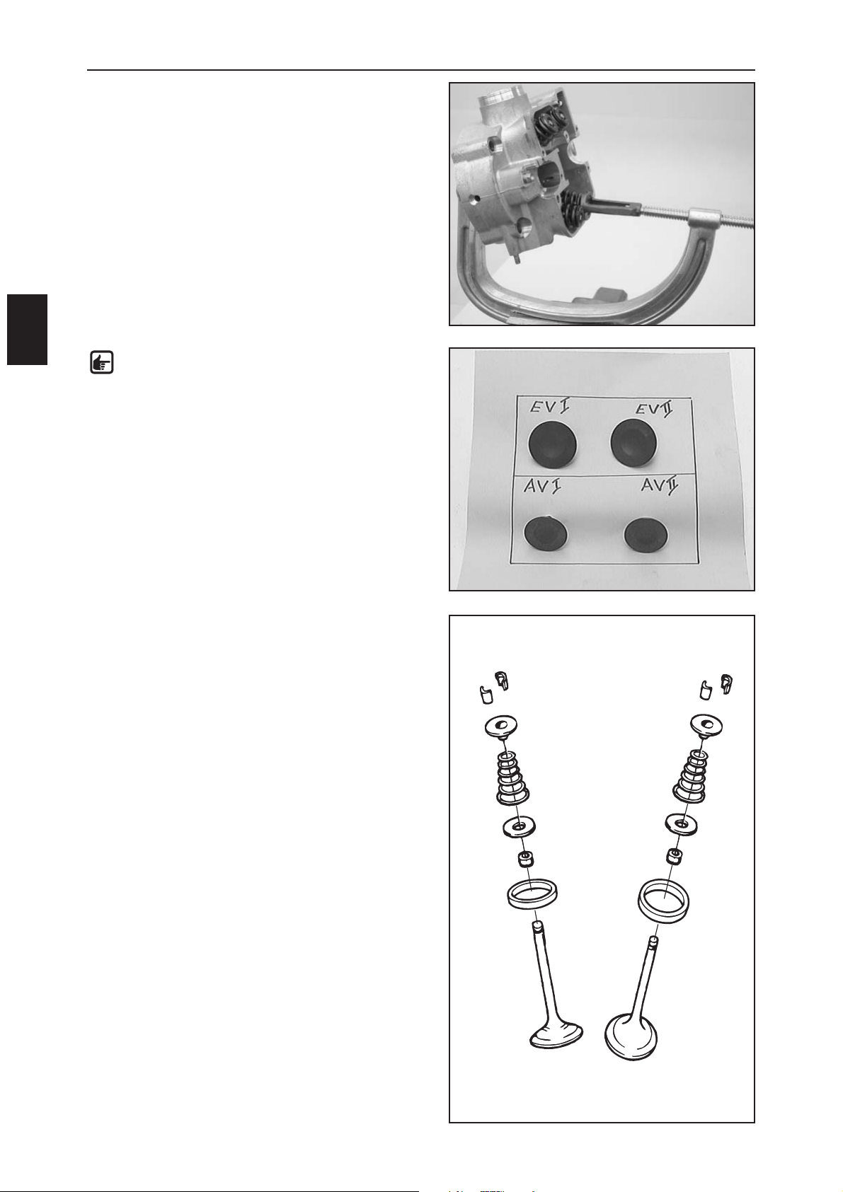
– Remove the 4 valves with the special tool
590.29.019.000.
NOTE: if you are mounting the used valves
again, they must be mounted in the same valve
guide as before. For this purpose, place the
valves in a box, marking the position they were
mounted in the cylinder head (see photo).
– Remove the valve spring retainer (1) and the valve
springs (2) from the cylinder head.
– Remove the spring retainer (3) and pull the valve shaft
seals (4) off of the valve guides.
Sealing area
Check the spark plug thread and the valve seats for
damage or cracks. Use a straight edge and a feeler
gauge to measure the sealing area to the cylinder for
distortion. Max. distortion 0.10 mm.
Valve seats
The valve seats may not be impacted. Width of sealing
seat: intake max. 1.50 mm; outlet max. 2.00 mm. Reseat
the valves if necessary.
Valves
Check the valve disk for wear and runout. The valve disk
runout should not exceed 0.05 mm. The valve seat may
not be impacted. The sealing area should be in the
middle of the valve seat. The valve shaft is hard-chromeplated. Wear usually occurs at the valve guide.
1
2
3
4
1
2
3
4
Page 46
SERVICING THE INDIVIDUAL PARTS
D
13
Valve guides
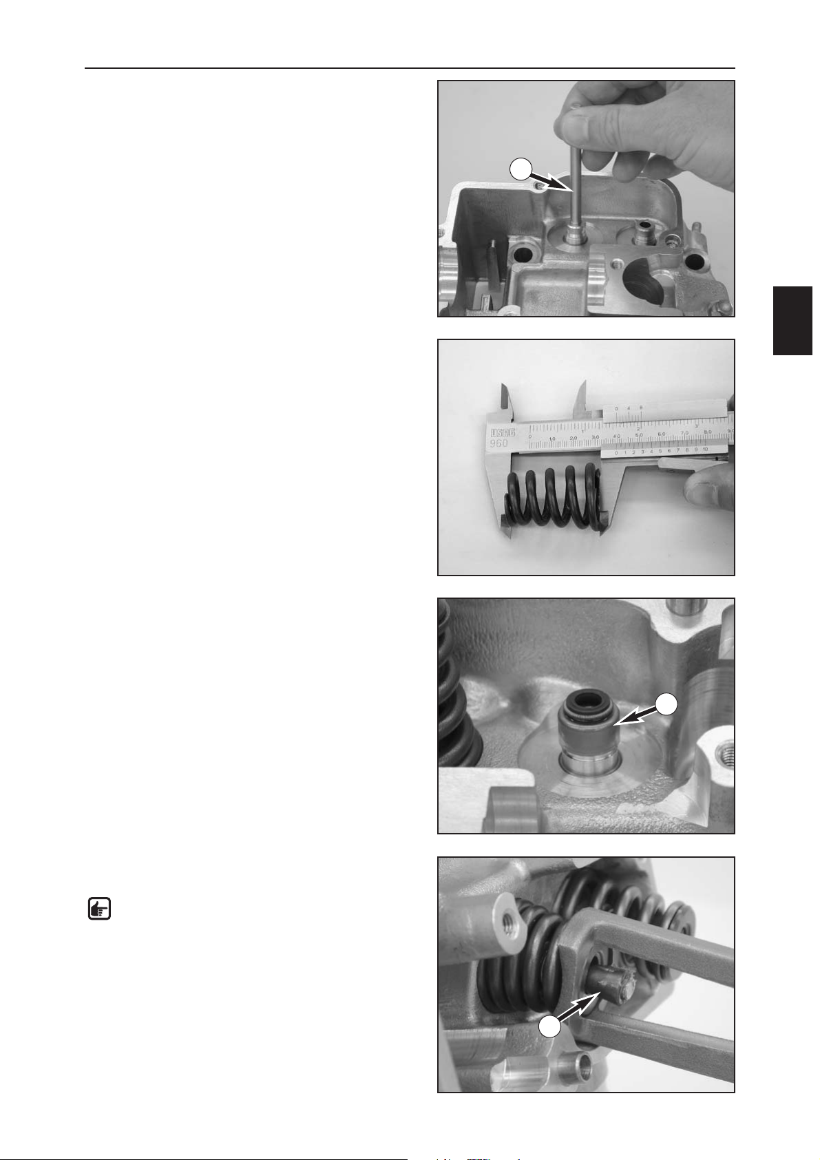
Use the limit plug gauge 590.29.026.006 (A) (Ø 6.05 mm)
to check the valve guides. If the limit plug gauge can
easily be pushed into the valve guide, the valve guide
needs to be replaced at a special workshop.
Valve springs
Check the valve springs for fractures or other wear (visual
check). Measure the spring length with a sliding gauge.
The minimum length may not be less than 38.30 mm.
Replace the spring if it is shorter.
Valve shaft seals
Always replace the valve shaft seals (1) if the valves are
dismounted.
– Mount the valve shaft seals on the valve guides and
oil.
–Place the 4 spring washers in the cylinder head.
–Oil the valves at the shaft and insert in the valve
guides in their original position.
– Mount the valve springs with the larger diameter
facing down, place the valve spring retainers in the
valve springs.
–Pretension the valve springs with the special tool and
mount the valve key (2).
NOTE: make sure the valve keys are seated
properly when mounted. Use a little grease to
position them on the valve.
–Tap on the valve spring retainers a few times with a
plastic hammer.
– Mount the chain tensioning rail, secure the bolt M5x16
with Loctite 243 and tighten to 6 Nm.
A
1
2
Page 47
SERVICING THE INDIVIDUAL PARTS
D
14
CAMSHAFT
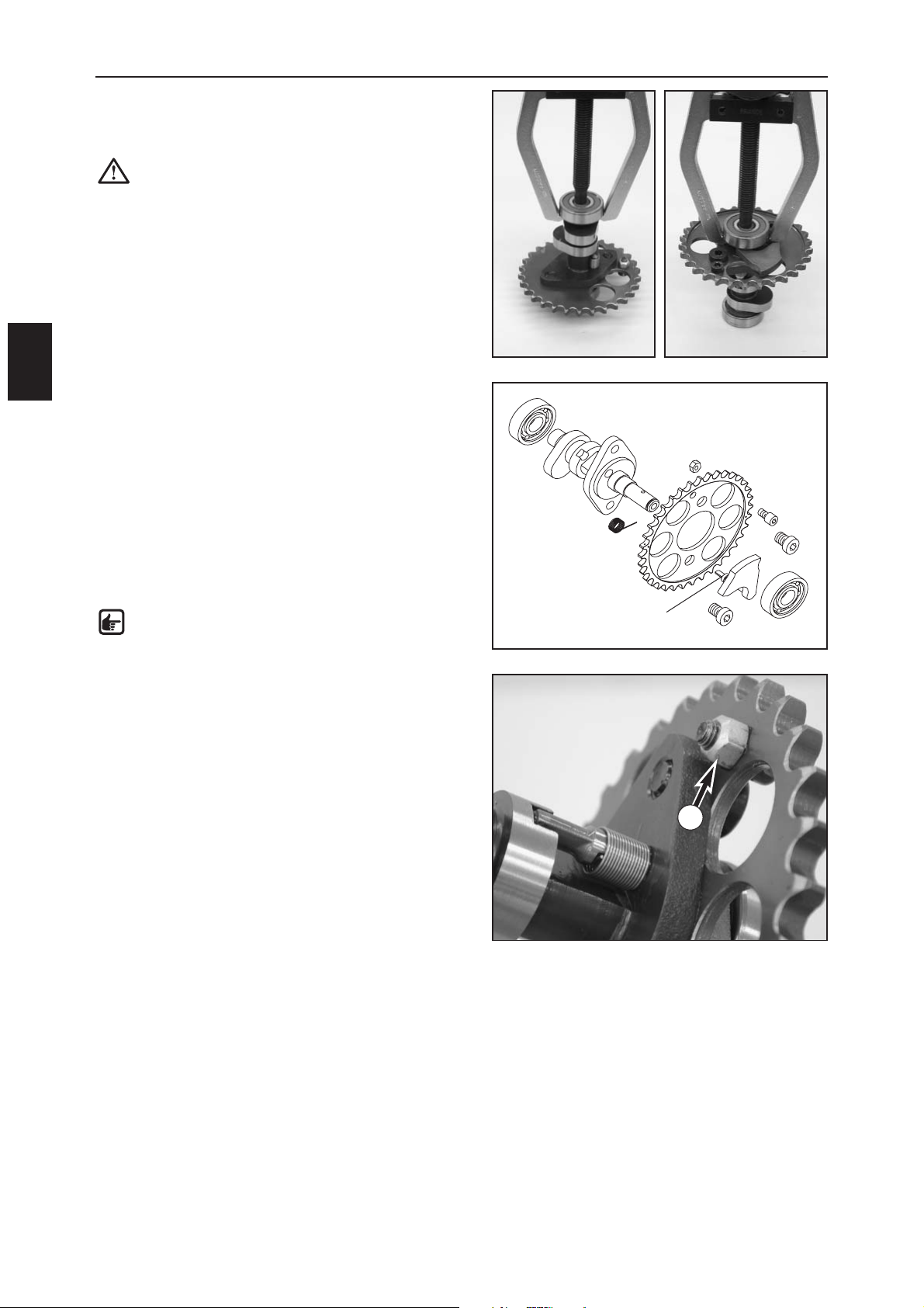
– Use the extractor 590.29.033.000 to pull both grooved
ball bearings (1) off of the camshaft (see illustration).
CAUTION: never clamp the camshaft in a vise
on the cams.
– Detach the spring (2) on the automatic decompression
shaft (3) while pulling the automatic decompression
shaft out of the camshaft.
–Loosen the 2 bolts M8x10 (4) and remove the camshaft
gear (5).
–Clean all of the parts, check and replace if necessary.
– Check the bearing seats in the camshaft and the cams
for wear.
– Replace both grooved ball bearings (1).
– Check the position of the automatic decompression
shaft (3) for clearance and contact surface to the rocker
arm for wear.
– Check the toothing on the camshaft gear (5) for wear.
– Check whether the bolt (6) on the automatic
decompression retainer has a tightening torque of
8 Nm.
NOTE: if you can turn the bolt, it needs to be
removed, cleaned, secured with Loctite 2701
and tightened to 8 Nm.
1
1
2
3
4
4
5
6
6
Page 48
SERVICING THE INDIVIDUAL PARTS
D
15
TIMING CHAIN TENSIONER
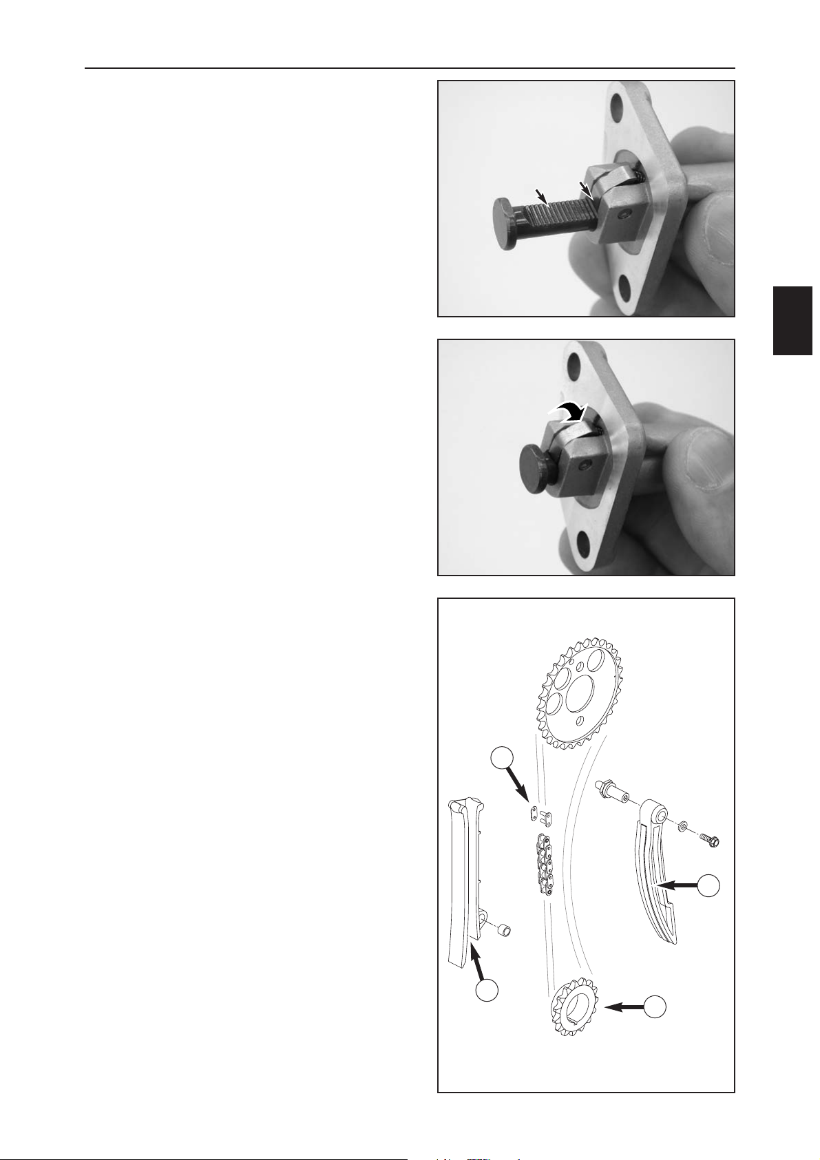
– Pull the pressure bolt all the way out of the timing
chain tensioner and check for smooth operation.
– Check the toothing on the pressure bolt and the
ratchet for wear.
–To mount, press the ratchet in the direction shown by
the arrow to keep the pressure bolt from locking and
push the pressure bolt all the way into the tensioner
housing.
TIMING TRAIN
Thoroughly clean all parts and check for wear.
Timing gear (1)
Check the toothing for breakout and wear
Tensioning rail (2)
Check for seizing marks at the contact surface.
Timing chain guide (3)
Check for seizing marks at the contact surface.
Chain link (4)
Replace the open chain link on the timing chain after it
was separated.
1
2
4
3
Page 49
SERVICING THE INDIVIDUAL PARTS
D
16
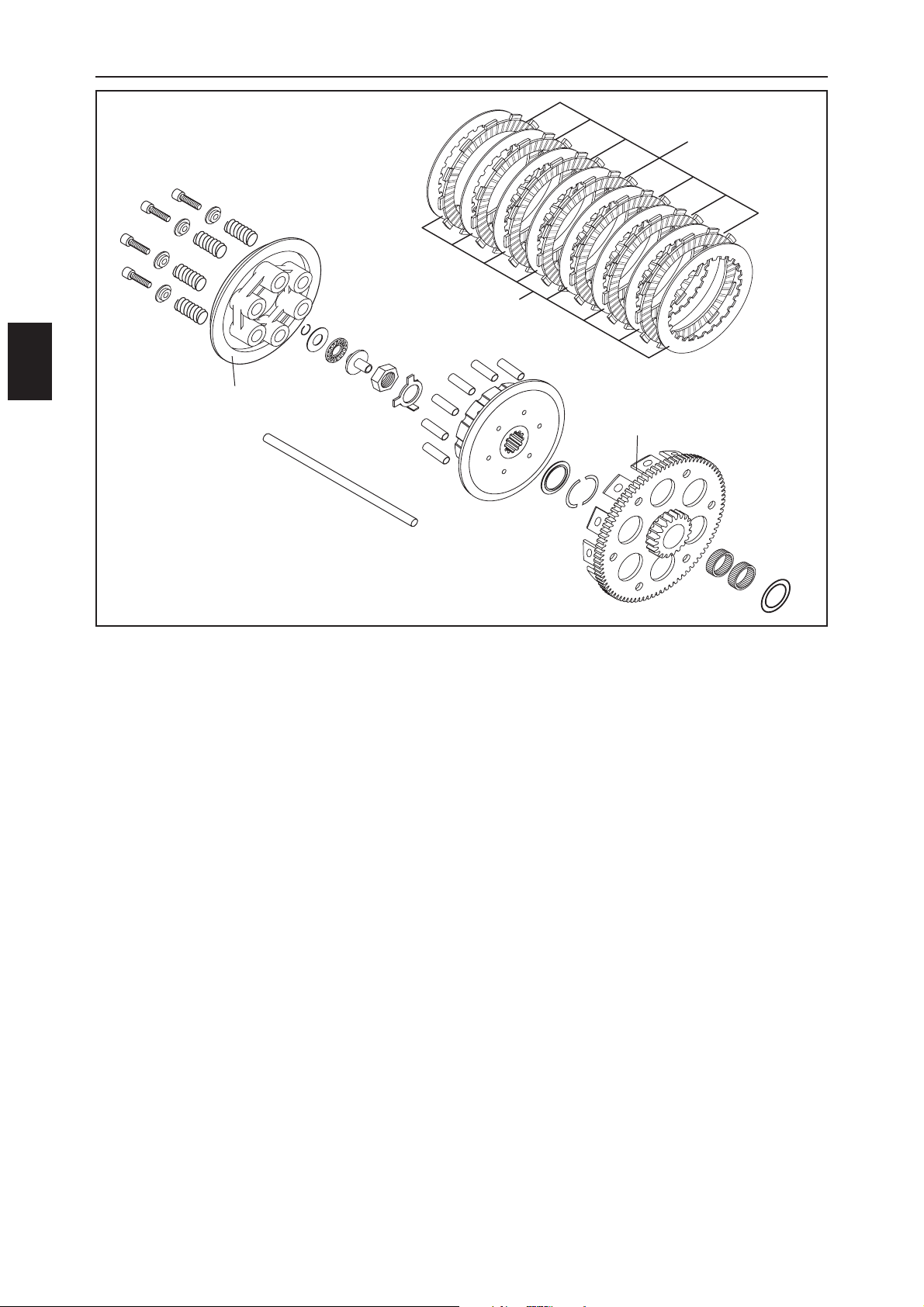
CHECKING THE CLUTCH FOR WEAR
Pressure piece (1)
Check for seizing marks and smooth operation.
Axial needle bearing (2)
Check for damage.
Push rod (3)
Place on a flat surface and check for eccentricity.
Clutch springs (4)
Minimum length 41.5 mm (new 43 mm), replace all 6 springs if necessary.
7 lining disks (5)
Minimum thickness 1.9 mm (new 2.0 mm). The lining disks must be flat.
8 clutch disks 1.0 mm (6)
The clutch disks must be flat. Check for mechanical damage. Replace the clutch disks if localized points are
broken off.
Inner clutch hub (7)
Check for seizing marks or damage.
Pressure cap (8)
Check the seating surface (A) of the steel disk for damage.
Outer clutch hub (9)
Check the thrust faces (B) of the lining disks and the outer clutch hub for wear. Replace the lining disks and the
outer clutch hub if the depressions are deeper than 0.5 mm.
Needle bearing (10)
Check for seizing marks or damage.
1
5
6
7
9
10
8
A
2
3
4
B
Page 50
SERVICING THE INDIVIDUAL PARTS
D
17
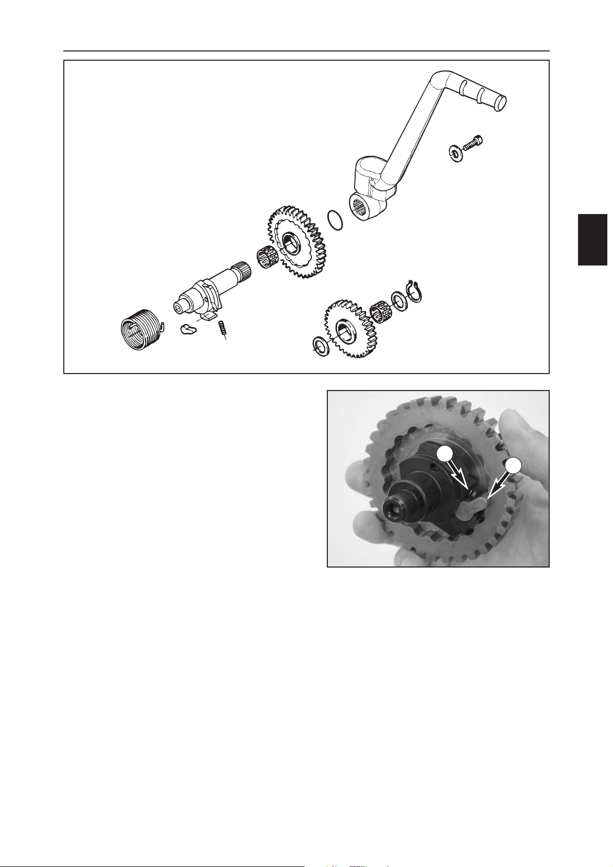
CHECKING THE KICKSTARTER FOR WEAR
Remove all parts from the kickstarter shaft, clean and
perform the following visual test:
– Check the toothing and the driver running surface on
the kickstarter wheel (1) for wear.
– Check the kickstarter shaft (2) for wear or damage.
– Check the inner clutch hub (3) and the driver spring (4)
for wear or damage.
– Check the toothing on the kickstarter idler (5) for wear.
– Check the clearance of both needle bearings (6).
– Check the kickstarter spring (7) for damage.
– Insert the driver spring in the kickstarter shaft, slide the
inner clutch hub into the recess.
– Slide the kickstarter wheel together with the needle
bearing onto the kickstarter shaft and make sure the
inner clutch hub engages.
1
6
2
7
3
4
5
6
3
4
Page 51
SERVICING THE INDIVIDUAL PARTS
D
18
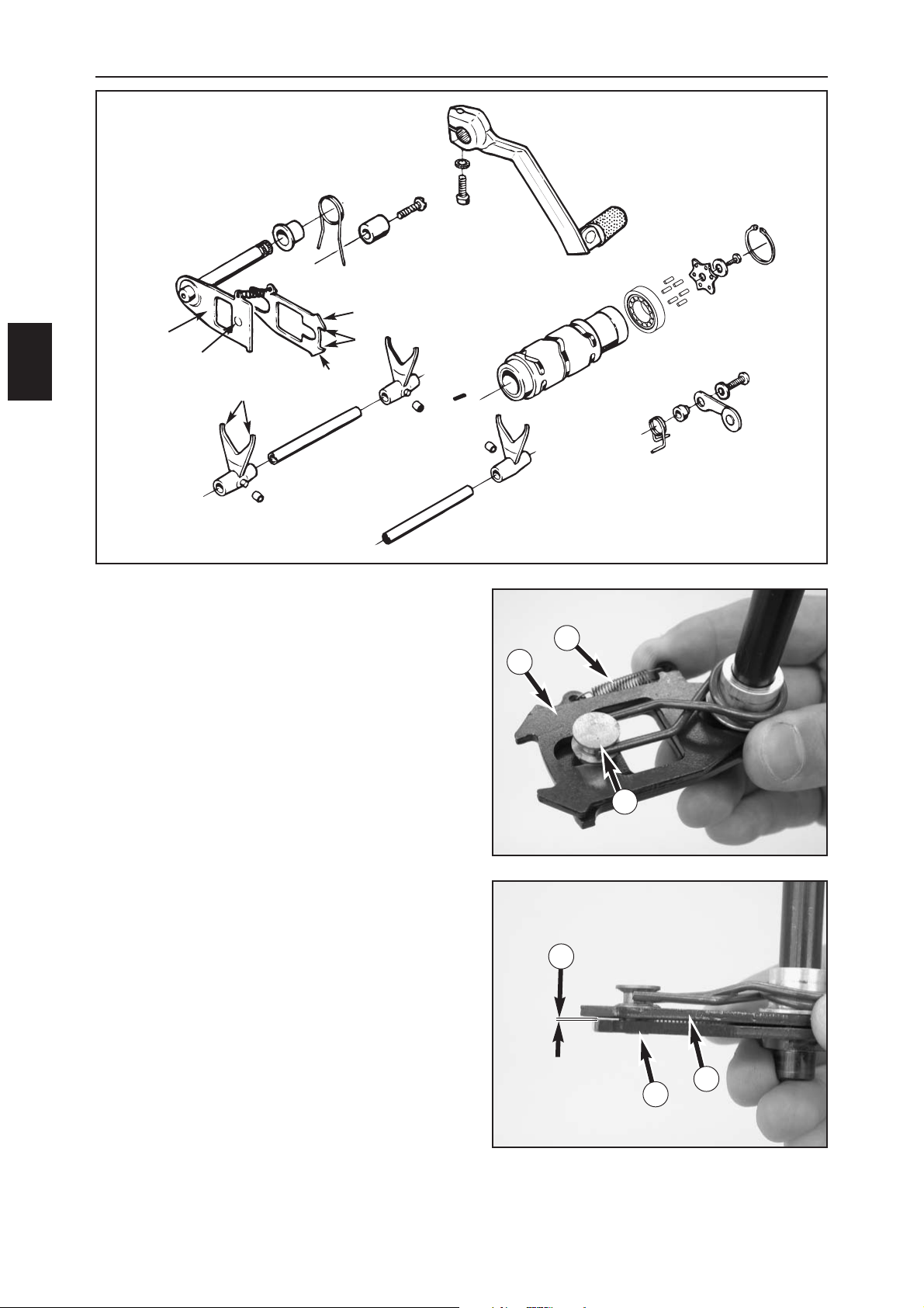
SHIFT MECHANISM
– Disassemble the shift shaft and clean the individual
parts.
– Check the shift forks (1) at the blade (A) for wear. They
are 3.9 mm thick when new; the wear limit is 3.6 mm.
– Check the shift grooves on the shift drum (2) for wear.
– Check whether the shift drum is properly seated in the
grooved ball bearing (3).
– Check the grooved ball bearing (3) for smooth
operation.
– Check the shift rollers (4) for pressure marks or cracks.
– Check the shift rails (5) for runout on a flat surface.
Also check for scores or seizing marks. Make sure the
shift forks run smoothly on the shift rails.
–
Check the shift rail (6) for wear at the points of contact (B).
– Check the return surface (C) on the shift rail for wear
(replace if excessively grooved)
– Check the guide bolt (D) for a tight fit and wear.
– Mount the shift rail (6) on the shift quadrant (7) and
attach the spring (8).
–Slide the bushing (9) and the return spring (10) with
the offset facing the shift quadrant, attach the return
spring to the guide bolt.
– Check the clearance (E) between the shift rail (6) and
shift quadrant (7). It should lie between 0.40 and 0.80
mm.
1
1
1
2
3
5
4
4
4
6
7
9
10
D
B
C
C
5
A
6
D
8
E
6
7
Page 52
SERVICING THE INDIVIDUAL PARTS
D
19
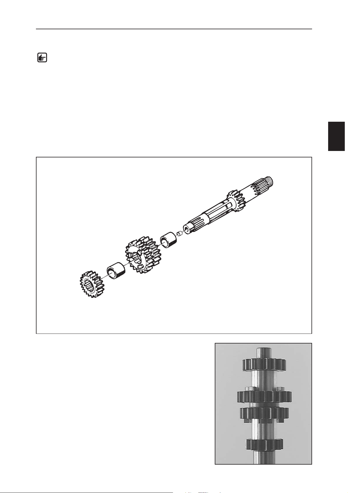
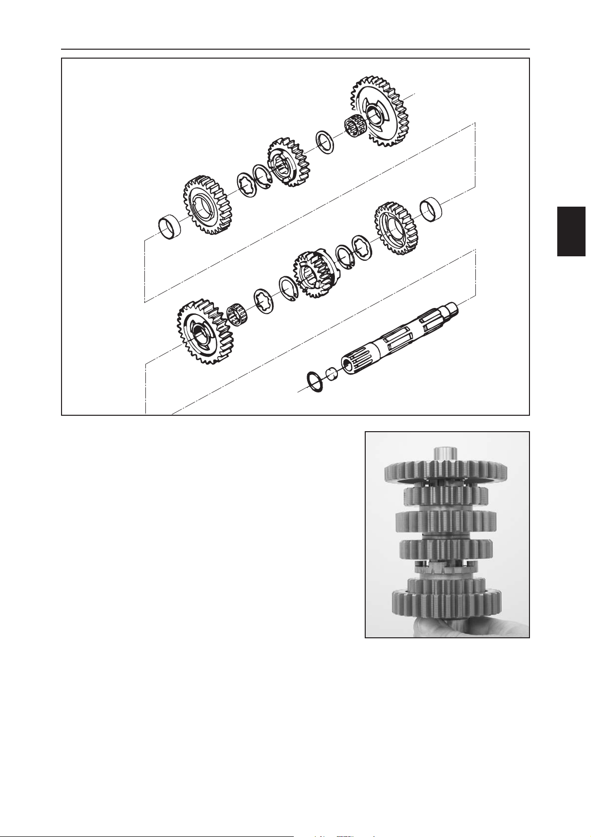
ASSEMBLING THE MAIN SHAFT (4-SPEED)
–Clamp the main shaft in a vise with the thread facing down (use
protective jaws).
– Carefully oil all parts before assembling.
– Mount the distance bushing (1) and the 3rd/4th gear sliding wheel
(2) with the small gear wheel facing down.
–Slip on the distance bushing (3) and the 2nd fixed gear (4) with the
inscription facing up, tap with a rubber hammer to the stop if
necessary.
– Finally, check all gears for smooth operation.
1
2
3
4
GENERAL INFORMATION ON WORKING WITH THE TRANSMISSION
Clamp the main shaft or countershaft in a vise (use protective jaws). Remove the gears.
NOTE: if the 2nd fixed gear cannot be removed from the main shaft, use the extractor
590.29.033.000 to pull it off together with the 6th idler gear.
Check the following parts for wear or seizing marks:
–Bearings
–Pivot points on the main shaft and countershaft and pivot points on the idler gears
– Shift dogs of the gears
–Tooth faces on all of the gears
–Tooth profiles on the main and countershaft as well as the corresponding gears
– Check all of the sliding gears for smooth operation in the profile
Carefully clean all parts and replace any damaged parts.
Always mount new circlips when you repair the transmission.
Page 53
SERVICING THE INDIVIDUAL PARTS
D
20
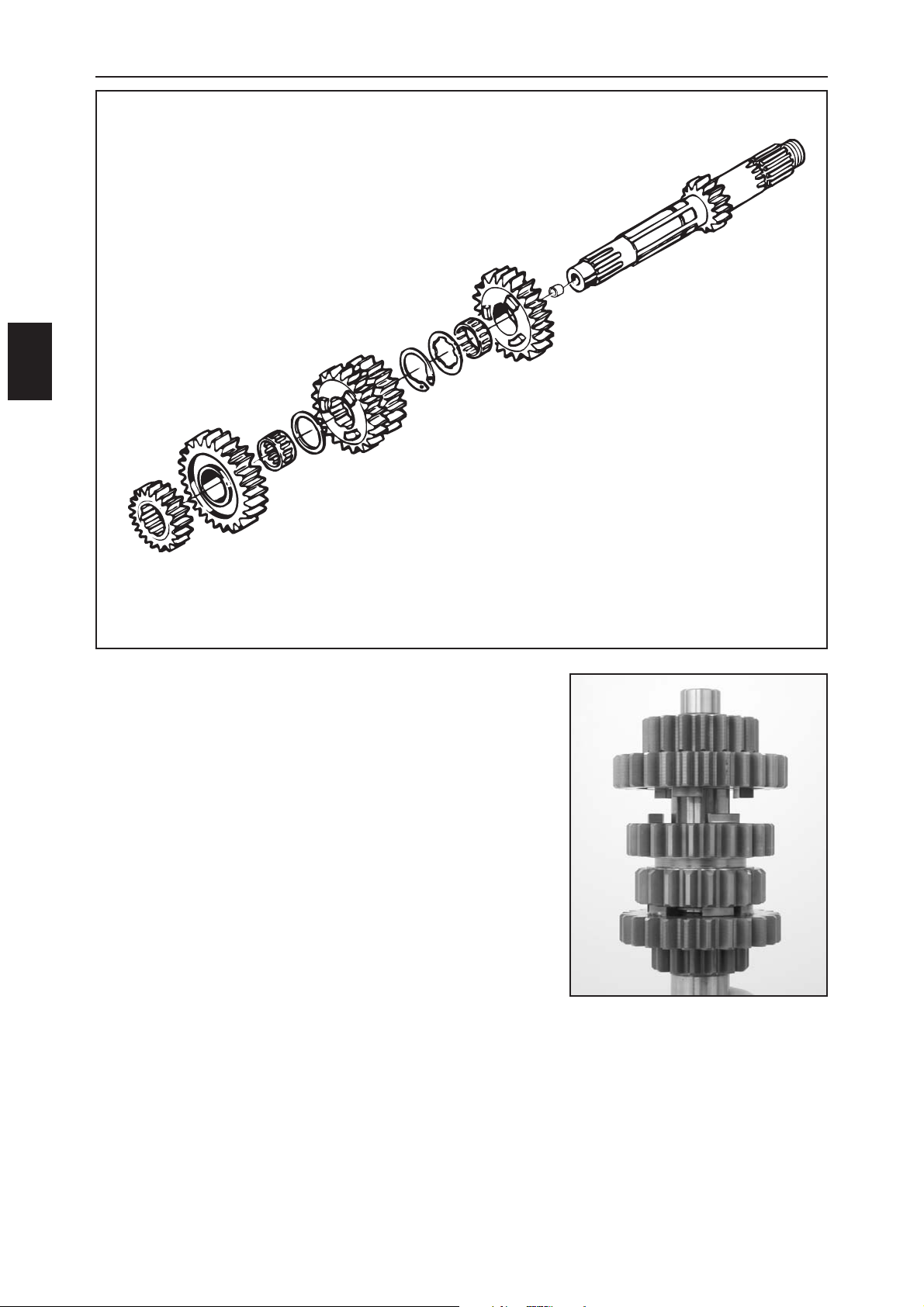
ASSEMBLING THE MAIN SHAFT (6-SPEED)
–Clamp the main shaft in a vise with the thread facing down (use
protective jaws).
– Carefully oil all parts before assembling.
– Mount the needle bearing (1), slip on the 5-speed idler (2) with the
shift dogs facing up.
– Mount the stop disk (3) (25.2x30x1 mm) and circlip (4) with the sharp
edge facing up.
–Slip on the 3rd/4th gear sliding wheel (5) with the small gear facing
down and mount the stop disk (6) (21x28x1 mm).
–Slip on the needle bearing (7) aufstecken and the six-speed idler (8)
with the shift dogs facing down.
–Slip on the 2-speed fixed gear (9) with the inscription facing up, tap
with a rubber hammer to the stop if necessary.
– Finally, check all gears for smooth operation.
2
1
3
4
5
6
7
8
9
Page 54
SERVICING THE INDIVIDUAL PARTS
D
21
ASSMBLING THE COUNTERSHAFT (4-SPEED/6-SPEED)
–Clamp the countershaft in a vise with the toothing for the Ritzel
facing down (use protective jaws).
– Carefully oil all parts before assembling.
– Mount the needle bearing (1) and the 2nd gear idler (2) on the
countershaft with the recess for the shift dogs facing up.
– Mount the stop disk (3) (25.2x32x1 mm) and the circlip (4) with the
sharp edge facing up.
– Mount the 6th gear sliding wheel (5) with the shift groove facing up.
– Mount the circlip (6) and the stop disk (7) (25.2x32x1 mm).
– Mount the 2 transmission gear bushings (8+9) and the 4th gear idler
(10) with the recess for the shift dogs facing down.
–Mount the 3rd gear idler (11) with the recess for the shift dogs facing
down.
– Mount the stop disk (12) (25.2x32x1 mm) and the circlip (13).
– Slip on the 5-speed sliding wheel (14) with shift groove facing down
and the stop disk (15) (21x28x1 mm).
– Mount the needle bearing (16) and 1st gear idler (17) with the recess
facing down.
– Finally, check all gears for smooth operation.
2
1
3
4
5
6
7
10
11
12
13
14
15
16
17
8
9
Page 55
SERVICING THE INDIVIDUAL PARTS
D
22
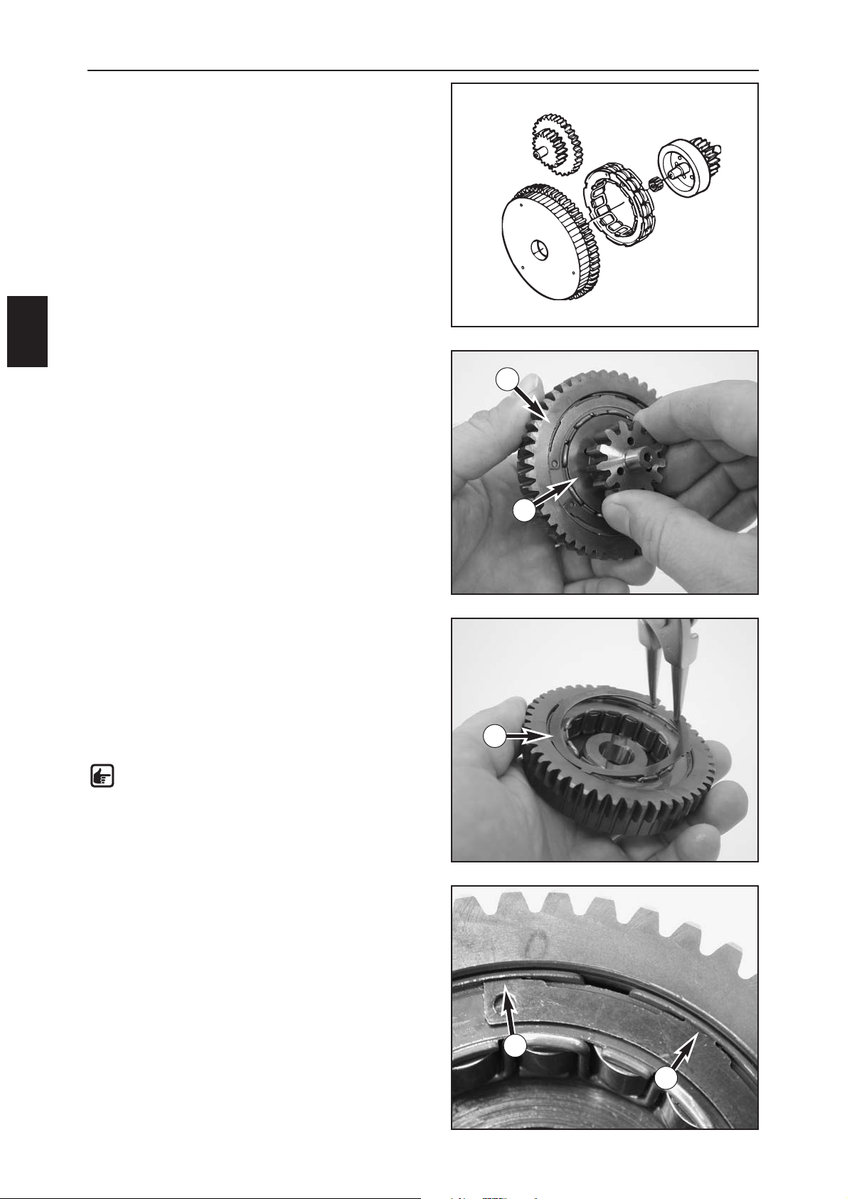
STARTER DRIVE
– Check the toothing and the pivot point on the starter
idler (1) for wear. Also check the bearing bolt for
running marks.
– Check the toothing and pivot point on the freewheel
gear (2) for wear. Also check the bearing bolt on the
freewheel gear for running marks.
– Remove the freewheel gear from the freewheel and
check the points of contact for pressure marks.
–Dismount the freewheel (3) from the freewheel gear
(see below), check the freewheel segments for wear.
– Check the freewheel gear toothing (4) and points of
contact to the freewheel for wear and pressure marks.
– Replace the O-ring on the starter flange.
CHECKING THE FREEWHEEL
– Insert the freewheel gear (2) in the freewheel (4).
– You should be able to move the freewheel gear in a
counterclockwise direction.
– The freewheel gear must lock in a clockwise direction.
REPLACING THE FREEWHEEL HUB
–Press the spacer ring (5) together with circlip pliers and
remove.
–Lift the freewheel out of the freewheel gear.
–
Oil the freewheel (3) and insert in the freewheel gear (4).
–Use circlip pliers to insert the spacer ring in the groove
and check for a good fit. Carefully tap on the mounted
spacer ring with a punch.
NOTE: the tabs (A) on the spacer ring must
engage in the recesses in the freewheel gear.
1
2
3
4
A
A
5
2
4
Page 56
ASSEMBLING THE ENGINE
E
1
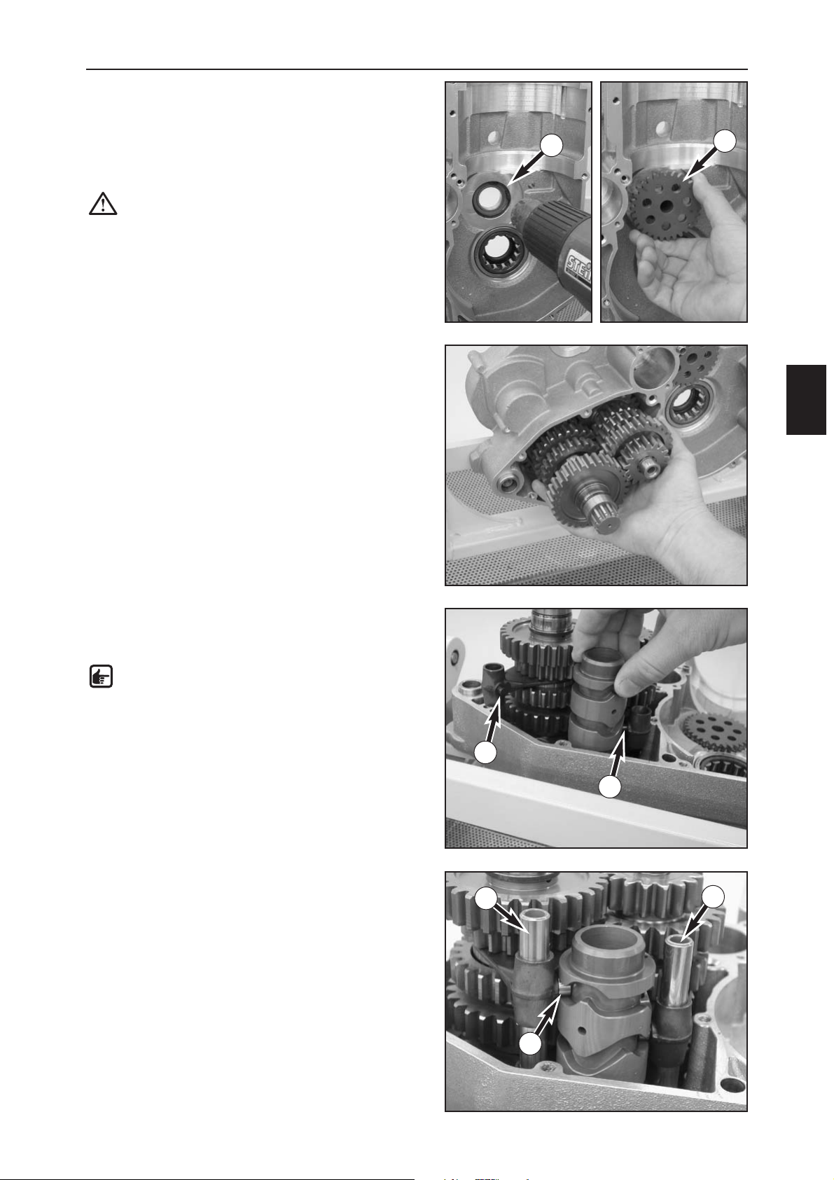
MOUNTING THE IDLER SHAFT
– Clamp the left housing half in the universal engine
work stand.
– Briefly heat the bearing (1) of the idler shaft (2) with a
hot-air blower and mount the idler shaft, carefully
tapping with a plastic hammer to the stop if necessary.
CAUTION: do not heat the bearing too long or
you will damage the bearing sealing.
– Connect both transmission shafts and insert in the
bearings.
– Move the engine case into a horizontal position and
insert the the shift forks in the shift grooves, the
driving pin (3) of the shift forks must be aligned.
NOTE: all three shift forks are identical.
–Turn the shift drum until it can be pushed into the
bearing seat with the circlip past the 1st idler gear.
– Mount the shift rolls (4) on the driving pin, fix with a
little grease if necessary.
–Attach the shift forks to the shift drum and mount the
shift rails (5) and (6), the longer shift rail (5) is used for
the countershaft shift forks.
3
3
4
1
2
5
6
Page 57
ASSEMBLING THE ENGINE
E
2
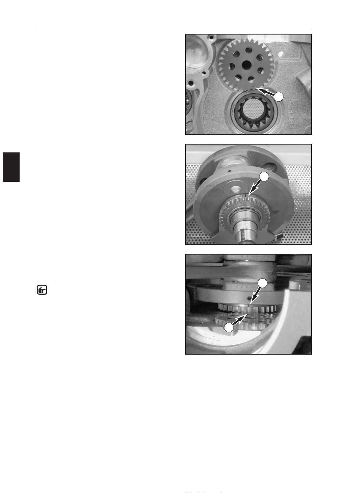
MOUNTING THE CRANKSHAFT
–Turn the mark on the idler shaft gear (1) towards the
bottom as shown in the photo.
– The toothing on the balance weight has a punch mark
(2) between 2 teeth directly opposite the
compensating mass. Use a felt-tip pen to draw the
mark on the outer side of the balance weight (see
photo).
– Screw the mounting sleeve 800.29.005.000 on the left
end of the crankshaft.
– Position the crankshaft in the engine case, making sure
both marks are aligned.
NOTE: to make sure the marks are aligned,
gradually push the crankshaft into the bearing
seat, checking the position of the marks. It will
not be possible to check their position after the
crankshaft is mounted.
– Unscrew the mounting sleeve 800.29.005.000.
1
2
1
2
Page 58
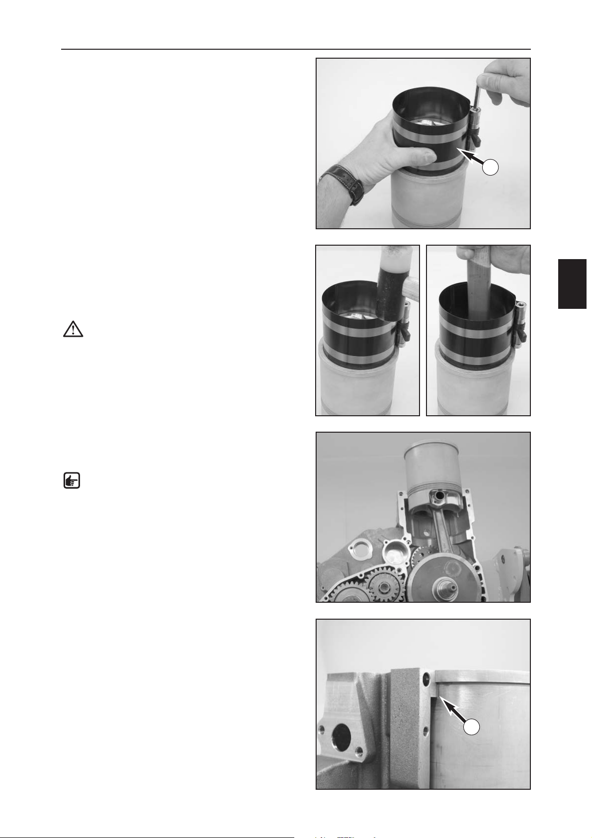
ASSEMBLING THE ENGINE
E
3
– Mount new O-rings on the cylinder liner and lubricate
with a little oil.
– Position the well-lubricated piston on the cylinder liner
and clamp the piston rings together with the piston
ring clamp 600.29.015.000 (1).
–Tap on the top of the piston ring clamp with a hammer
to make it fit flush with the cylinder liner.
– Carefully tap the piston into the cylinder liner with the
hammer handle, making sure the piston rings do not
get caught.
CAUTION: if the piston ring clamp presses the
piston rings together properly and flush around
the entire cylinder, you will be able to push the
piston into the cylinder by tapping lightly with
the hammer handle. Excessive force usually
damages the piston rings.
– Insert the cylinder liner and piston in the engine case,
insert the piston pin and mount a new piston pin
retainer.
NOTE: the arrow mark on the piston must point
to the exhaust side.
–Turn the cylinder liner until the mark (2) is aligned with
the engine case, i.e. the recess in the cylinder liner is
positioned at the idler shaft.
1
2
Page 59
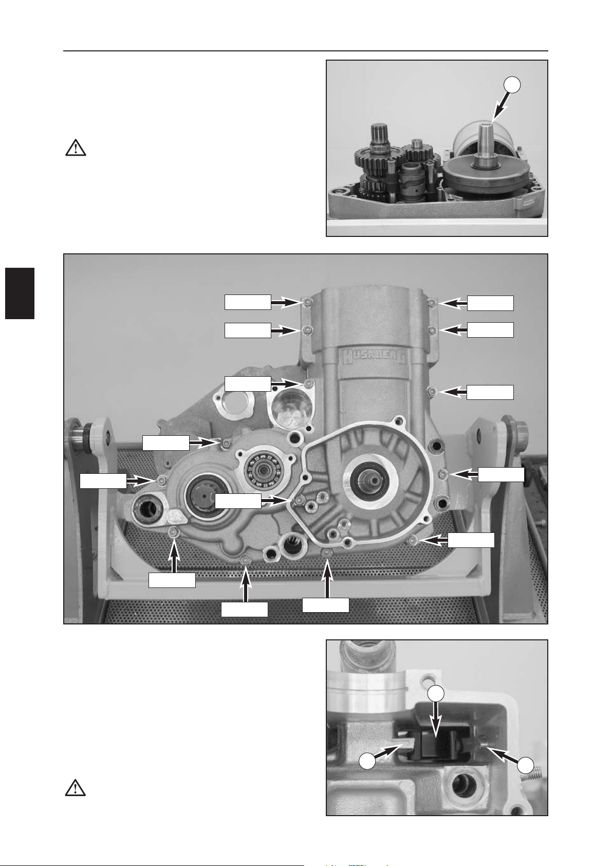
ASSEMBLING THE ENGINE
E
4
– Remove the protective sleeve.
– Mount the bolts (see above photo for bolt lengths) and
tighten slightly.
–Tap the cylinder liner down and tighten the bolts from
the inside to the outside to 10 Nm.
–After tightening, check all shafts for smooth operation
and lock the crankshaft in the TDC position.
MOUNTING THE CYLINDER HEAD
– Put a new cylinder base gasket in place and mount the
cylinder head (do not forget the sleeves).
CAUTION: run the chain guide rail (2) between
the two locating tabs (3).
M6x45
– Degrease the sealing areas on both engine case halves
and apply a thin coat of silicone gasket sealant 309098
to the sealing area on the left housing half; mount the
dowels
–Place protective sleeve 800.29.105.000 on the
crankshaft (1) mount the right engine housing half.
CAUTION: do not try to draw the two housing
halves together with the housing bolts. If
necessary, carefully tap on the housing near the
bearings with a plastic hammer.
M6x40
M6x40
M6x50
M6x50
M6x60
M6x65
M6x35
M6x50
M6x50
M6x50
M6x50
M6x60
M6x45
3
3
2
1
Page 60
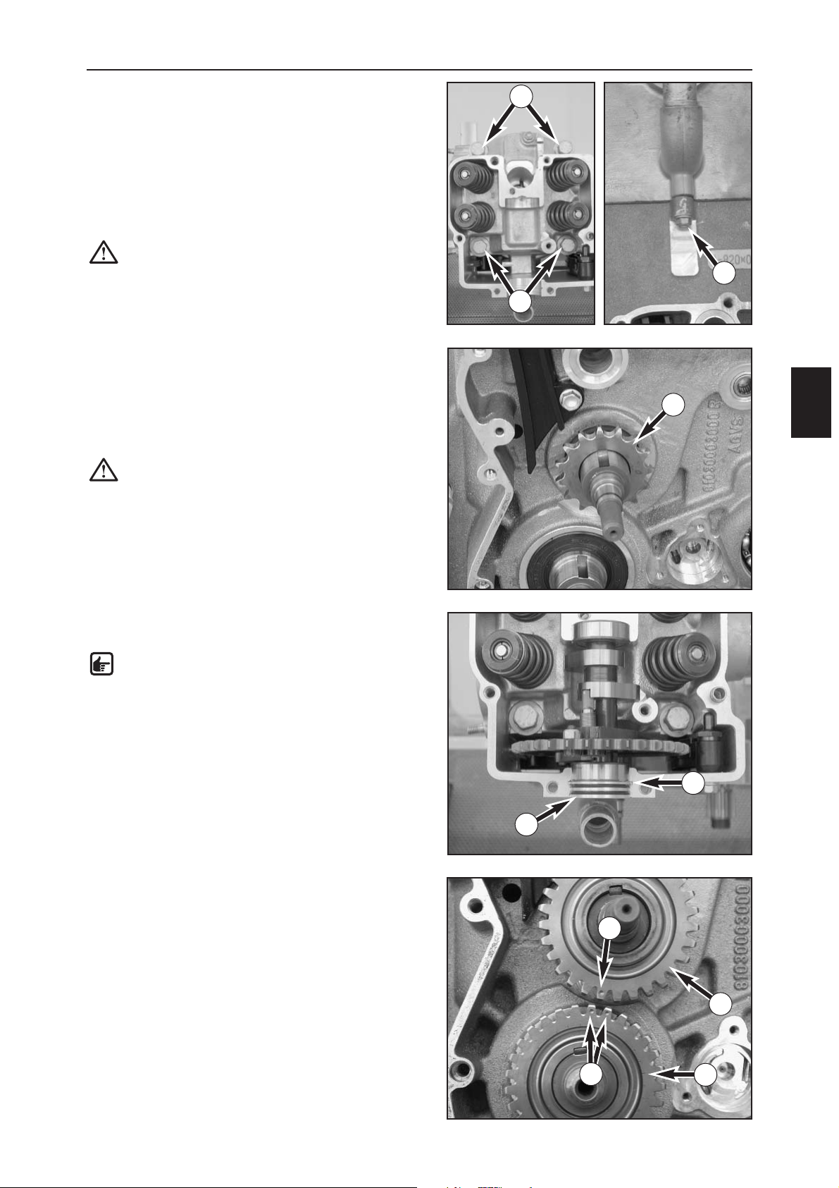
ASSEMBLING THE ENGINE
E
5
– Screw on the oiled cylinder head bolts (1) with the
washers.
–Tighten the cylinder head bolts crosswise until you feel
a slight resistance.
–Tigthen the cylinder head bolts crosswise to 40 Nm.
–Tighten the cylinder head bolts crosswise to 50 Nm.
– Secure the lateral cylinder head bolt (2) with Loctite
243 and tighten to 10 Nm.
CAUTION: do not tighten the lateral cylinder
head bolt any tighter since you may damage
the feeder on the engine case.
MOUNTING THE TIMING CHAIN
–Mount the woodruff key for the rear sprocket (3) in the
idler shaft groove.
–Heat the rear sprocket on the idler shaft on a hotplate
to approx. 100° C and immediately slide on the idler
shaft with the collar on the inside.
CAUTION: do not mount the rear sprocket in a
cold condition since you may damage the idler
shaft ball bearing or cause the idler shaft to be
pressed towards the inside.
– Mount the camshaft with the cap (4) in the cylinder
head, insert new, oiled O-rings in the cap.
NOTE: the collar (5) of the cap must engage in
the cylinder head groove.
– Lock the crankshaft with the locking bolt
580.30.080.000.
–Place the woodruff keys in the shaft grooves of the
idler shaft and crankshaft.
–Mount the primary pinion (6) and idler shaft gear (7),
turn the idler shaft until the marks (8) on the two gears
are aligned.
2
1
1
3
5
4
6
7
8
8
Page 61
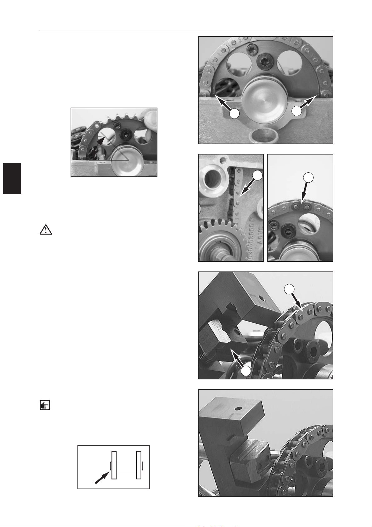
–Turn the camshaft gear until the marks (1) are aligned
with the edge of the cylinder head.
–Allow the chain to fall into the chain compartment on
the guide side; insert the end of the chain at approx.
45º (see photo).
–Continue to turn the camshaft gear in a clockwise
direction one complete rotation until the marks are
aligned again. The end of the chain will be just in front
of the rear sprocket on the idler shaft in this position.
– Run the 2nd end of the chain around the rear sprocket
on the idler shaft and check the marks again.
– Mount the chain link (2) to close the chain and
continue turning the chain until the chain joint (3) can
be easily mounted and secured.
CAUTION: when you are finished, align the rear
sprockets with the marks again, making sure
that the cams on the camshaft point down
(towards the cylinder head).
Proceed as follows to lock the timing chain:
– Mount a new chain link.
– Apply the insert (4) of the special tool 800.29.030.000
as shown in the photo and lock the chain link (5) by
tightening the tool spindle.
–Turn the special tool insert and rivet the link.
NOTE: rivet the link so tightly until the ends of
the link have a trapezoidal cross section (see
drawing)
ASSEMBLING THE ENGINE
E
6
1
1
2
3
4
5
45º
Page 62
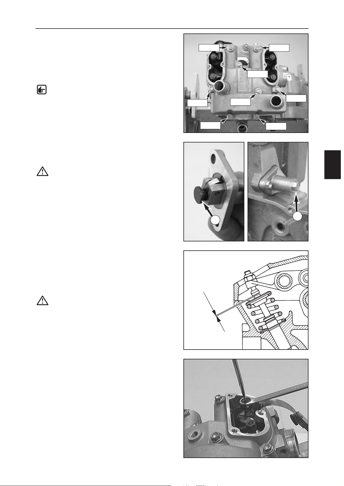
ASSEMBLING THE ENGINE
E
7
– Degrease the sealing area on the cylinder head and
the cylinder head top section and apply a thin layer of
silicone gasket sealant 309098 to the sealing area of
the cylinder head.
– Mount the dowels and the cylinder head top section.
– Mount the bolts and tighten to 10 Nm (see photo for
bolt lengths).
NOTE: mount the M6x55 and M6x60 bolts with
new copper sealing washers.
MOUNTING THE TIMING CHAIN TENSIONER
– Mount the timing chain tensioner with a new gasket
but without the spring and plug.
CAUTION: make sure that the pressure bolt is
completely retracted (see photo), otherwise the
timing chain will be overtensioned.
– Mount the 2 bolts (M6x20) and tighten to 10 Nm.
– Use a screwdriver to press in the pressure bolt until
you feel a slight resistance. Then press in one notch
further.
–Mount the pressure spring and plug with a new seal
ring and tighten to 10 Nm.
ADJUSTING THE VALVE CLEARANCE
– The valve clearance (A) is measured between the valve
shaft and the adjusting screw when the engine is cold.
Valve clearance: 0.12 mm
CAUTION: if the piston is not in the top ignition
dead center position, the valves will be
actuated by the rocker arms and the valve
clearance cannot be correctly adjusted. In this
case, turn the engine one revolution further and
lock again.
– After adjusting, check the valve clearance again and
tighten the counternuts to 11 Nm.
– Mount the 2 valve covers with new gaskets and bolts
(AH M5x15 bolt). Tighten the bolts to 6 Nm.
1
2
A
M6x25
M6x35
M6x25
M6x45
M6x35
M6x55
M6x55
M6x60
Page 63
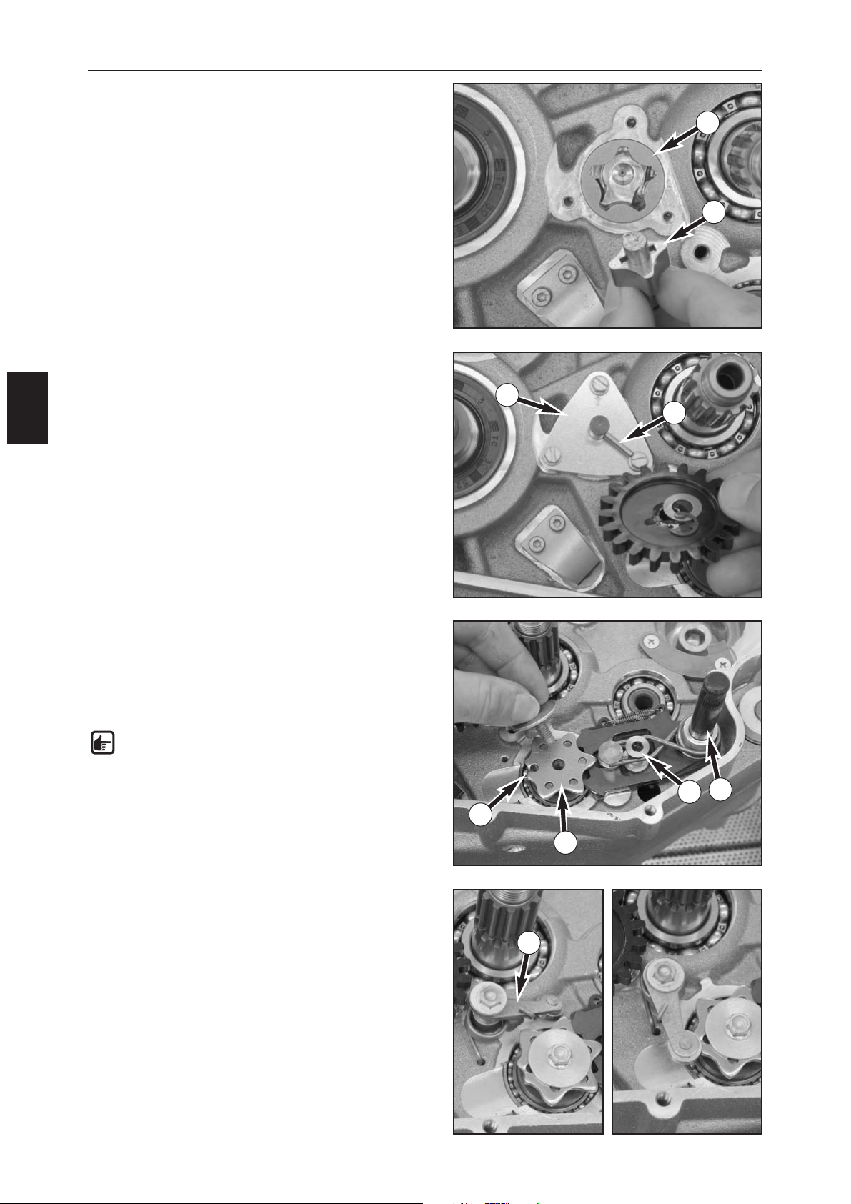
MOUNTING THE OIL PUMP
–Oil the outer rotor (1) and insert in the engine case
with the mark towards the inside (the mark should no
longer be visible once mounted).
– Insert the pin in the oil pump shaft and slide on the
inner rotor (2).
– Mount the shaft with the inner rotor, the mark on the
inner rotor pointing towards the outside (the mark
should still be visible once mounted).
–Attach the oil pump cover with the arrow pointing up,
secure the screws (M4x12) with Loctite 243 and tighten
to 5 Nm.
– Insert the pin in the oil pump shaft, attach the oil
pump gear, slip on the washer and mount the circlip in
the groove of the oil pump shaft.
– Check the oil pump for smooth operation.
MOUNTING THE SHIFT MECHANISM
– Mount the shift shaft (5), secure the bolt (6) with
Loctite 243 and tighten to 10 Nm.
–Place the (smaller) washer on the shift drum and mount
the shift lock (7) on the shift drum.
NOTE: The shift drum pin with the colored
marks must engage in the hole next to the flat
part (8).
– Apply Loctite 243 to the thread of the M6x20 bolt and
screw into the shift drum together with the larger
washer. Tighten to a torque of 10 Nm.
– Insert the bolt (M6x25) through the locking lever (9),
position the sleeve with the collar facing up and attach
the spring.
– Secure the bolt with Loctite 243 and insert the spring
in the hole in the engine case. Tighten the bolt several
turns.
– Swing the locking lever against the spring force and
allow to rest against the shift lock.
– Mount the locking lever on the sleeve and tighten the
bolt to 10 Nm.
ASSEMBLING THE ENGINE
E
8
1
2
3
4
5
6
7
8
9
Page 64
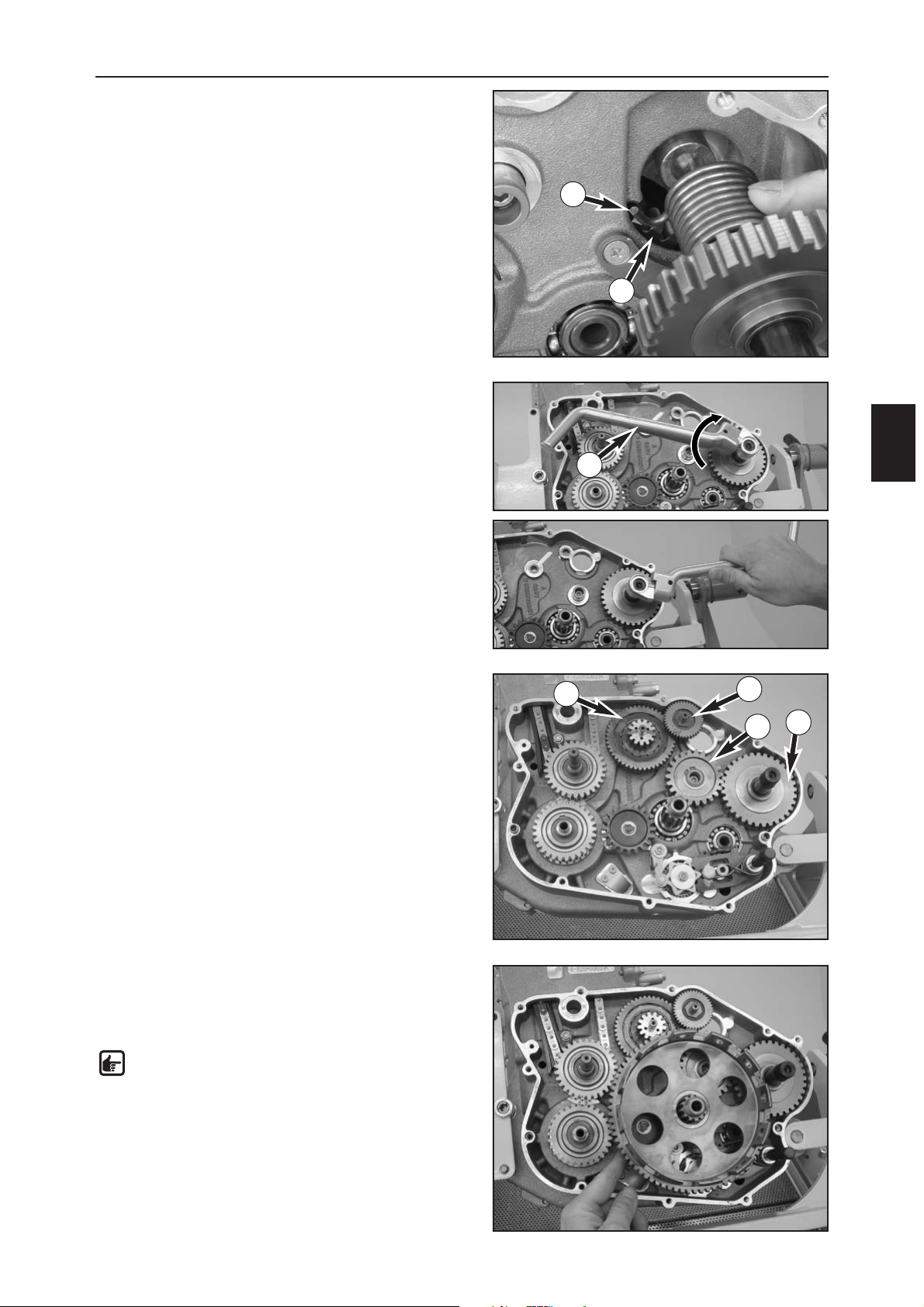
ASSEMBLING THE ENGINE
E
9
MOUNTING THE KICKSTARTER SHAFT
–Attach the kickstarter spring (1) behind the
transmission gear (2) in the engine case and push the
kickstarter shaft into the bearing seat.
– Slide the kickstarter (3) on the kickstarter shaft as
shown in the photo.
–Turn the kickstarter shaft with the kickstarter half a turn
in a clockwise direction (to pretension the spring), slide
the kickstarter shaft into the housing all the way to the
stop and relieve the kickstarter.
Check the kickstarter pinion (4) for proper functioning: if
the kickstarter is not actuated, the kickstarter pinion can
be cranked without resistance.
The driver will not engage until the kickstarter is turned in
a clockwise direction; the kickstarter pinion will lock when
turned in a counterclockwise direction.
– Remove the kickstarter.
– Slide the kickstarter idler (5) with the needle bearing,
the upper and the lower washer on the bearing bolt
and mount the circlip.
– Mount the starter idler (6) and the freewheel (7)
together with the freewheel needle bearing.
MOUNTING THE CLUTCH
–Slide the washer on the transmission main shaft, mount
the two needle bearings and slide on the outer clutch
hub.
NOTE: since the outer clutch hub must engage
in the primary pinion, the gear on the idler
shaft, the freewheel, the kickstarter idler and
the oil pump gear, you may need to turn some
of the gears back and forth to get them to
engage more easily.
4
1
2
3
5
6
7
Page 65
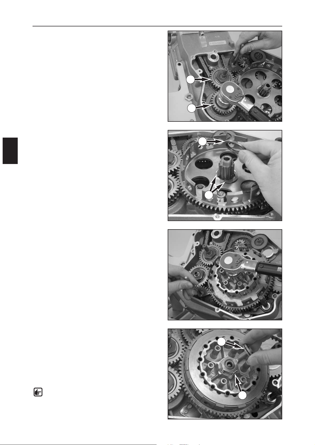
ASSEMBLING THE ENGINE
E
10
–Make sure the marks on the primary pinion and the
idler shaft gear are aligned and loosen the crankshaft
locking bolt 580.30.080.000.
– Lock the primary pinion (1) with the special tool
800.29.004.000 (gear segment) as shown in the photo,
apply Loctite 2701 to the thread of the nut M16x1
(30 mm) and tighten to 110 Nm.
– Lock the idler shaft (2) with the special tool
800.29.004.000 (gear segment) as shown in the photo,
apply Loctite 2701 to the thread of the nut M16x1
(30 mm) and tighten to 110 Nm.
–Place both semiwashers (3) in the groove of the
transmission main shaft and secure with the stepped
disk (4).
–Slip on the driver and lock washer, apply Loctite 243 to
the nut (27 mm) and screw on.
– Insert the clutch holder 800.29.003.000 with into the
outer clutch hub with at least 6 clutch sleeves, lock the
outer clutch hub with the gear wheel segment
(800.29.004.000) as shown in the photo and tighten
the nut to 120 Nm.
– Remove the clutch holder and bend up the the lock
washer (5) of the nut.
– Insert all of the clutch sleeves, fix with some grease if
necessary.
–Starting with one of the clutch disks, alternately insert
8 steel and 7 lining disks in the outer clutch hub,
ending with a clutch disk on top.
–Mount the push rod and the pressure piece (6).
NOTE: insert the thinner end of the push rod
into the pressure piece.
5
3
4
6
1
2
Page 66
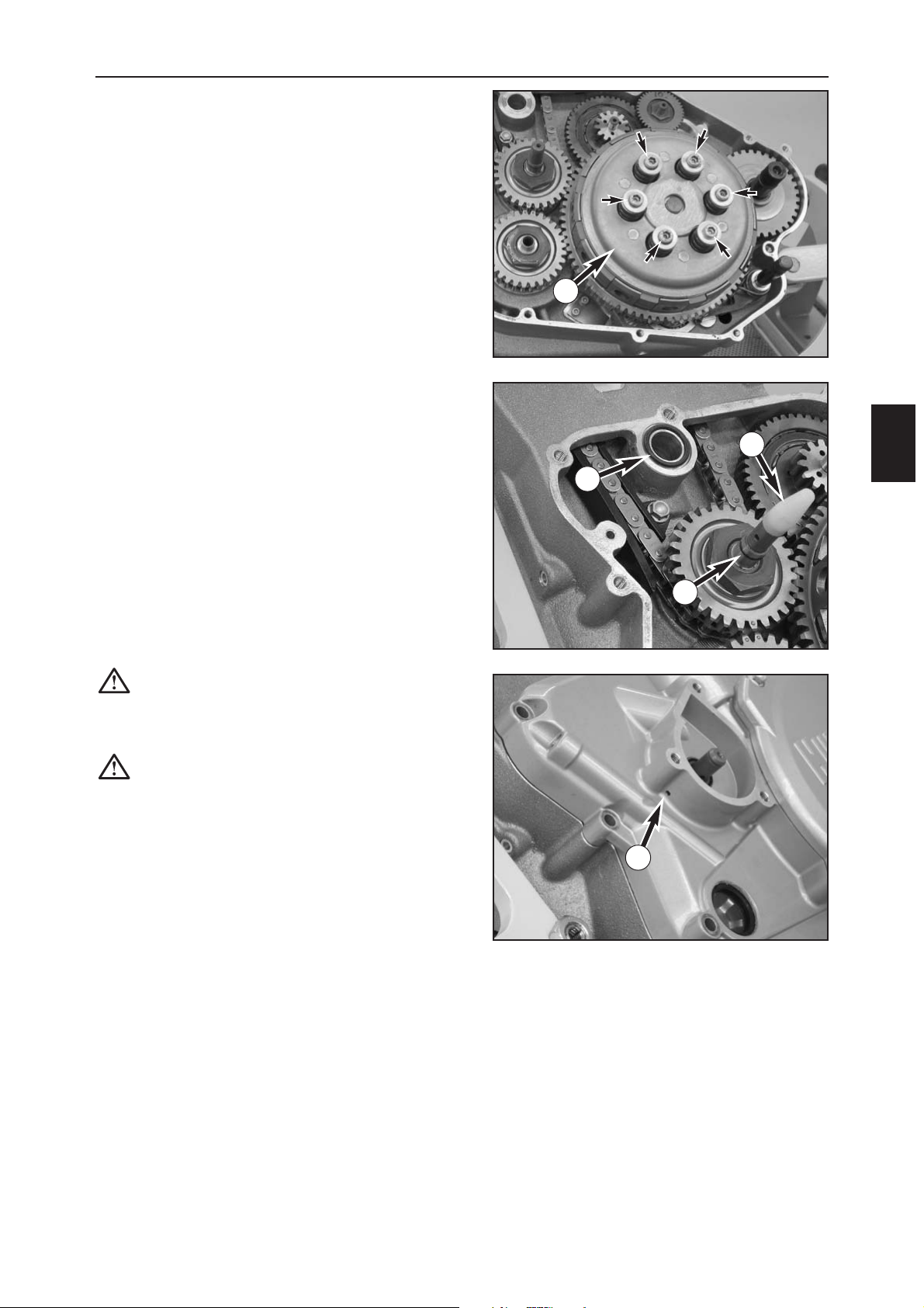
ASSEMBLING THE ENGINE
E
11
–Mount the pressure cap (1) with the collar bolts, clutch
springs and spring retainers.
– Secure the collar bolts with Loctite 243 and tighten in
several stages crosswise to 8 Nm.
MOUNTING THE CLUTCH COVER
– Insert a new O-ring in the groove around the water
duct (2).
– Mount a new O-ring on the water pump shaft (3) and
grease thoroughly.
–Place protective sleeves (590.29.005.010 (4) and
800.29.205.000) over the water pump shaft and
kickstarter shaft.
– Cover the teething of the shift shaft with isolation
tape.
– Mount the dowels and a new clutch cover gasket.
– Carefully mount the clutch cover, tapping lightly with a
plastic hammer if necessary.
CAUTION: do not draw the clutch housing to
the engine case with the bolts since it could
cant and break
– Remove the protection sleeves and the isolation tape.
CAUTION: if the O-ring on the water pump
shaft is damaged when mounting the clutch
cover, it will cause engine oil to leak out of the
hole (B).
1
2
3
B
4
Page 67
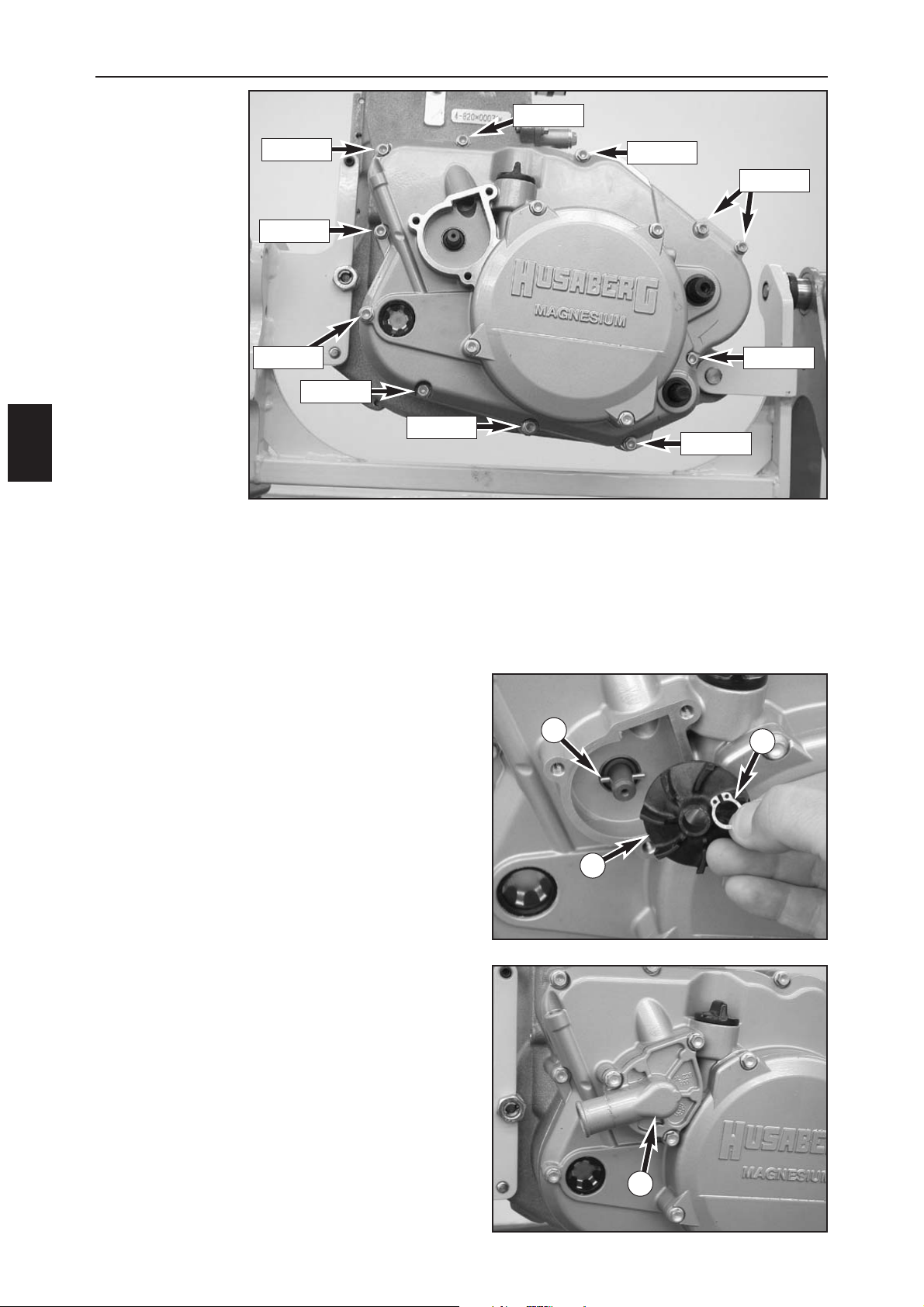
– Screw in the bolts (see photo for bolt lengths).
–Tightening torque: 10 Nm.
– Insert the pin (1) in the water pump shaft, slip on the
water pump wheel (2) and mount the circlip (3).
– Mount the water pump cover (4) with a new gasket,
tighten the M6x15 bolts to 10 Nm.
ASSEMBLING THE ENGINE
E
12
M6x25
M6x25
M6x30
M6x30
M6x25
M6x25
M6x25
M6x25
M6x25
M6x25
1
2
3
4
Page 68
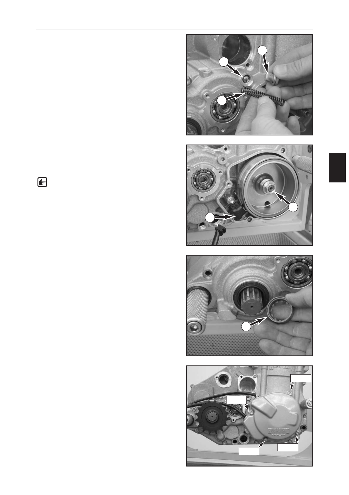
ASSEMBLING THE ENGINE
E
13
MOUNTING THE PRESSURE RELIEF VALVE
–Slide the ball (1) and spring (2) in the hole, screw in the
plug (3) with a new seal ring and tighten to 20 Nm.
MOUNTING THE ROTOR AND THE PICK UP
– Mount the ignition rotor and the nut (4) with
corrugated washer; make sure that the woodruff key is
mounted.
NOTE: LH thread!
– Lock the crankshaft (tighten the locking bolt
580.30.080.000) and the nut (17 mm) to 60 Nm).
– Remove the locking bolt again and screw in the M8x15
plug.
– Mount the pulse generator (5) with the M5x16 bolts,
secure the bolts with Loctite 243 and tighten to
6 Nm.
–Oil the distance bushing (6) and slide onto the
countershaft with the recess for the O-ring towards the
inside.
– Mount the generator cover with dowels and a new
gasket (see photo for bolt lengths) and tighten to 10
Nm.
– Slip the engine sprocket on the shaft and mount the
circlip.
–Use the spark plug wrench 590.29.072.000 to screw in
the spark plug and tighten to 20 Nm.
To mount the oil filter and the oil screen and add engine
oil: see Chapter A
M6x30
M6x35
M6x30
M6x25
1
2
3
4
5
6
Page 69

Page 70
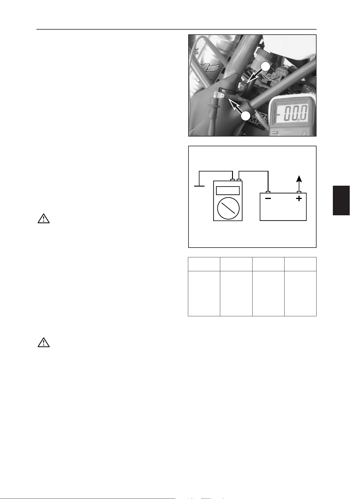
ELECTRIC SYSTEM
F
1
CHECKING FOR LOSS OF CURRENT
Check for loss of current before you check the voltage
regulator-rectifier.
– Switch off the ignition and disconnect the ground
cable (1) from the battery.
–Clamp an ampmeter between the ground cable and
the negative pole (2) of the battery.
Setpoint value: max. 2 mA
– If the value is lower than the setpoint value, look for
power consumers.
For example:
– Defective voltage regulator-rectifier
–Creepage current in the socket connectors
DISMOUNTING/MOUNTING THE BATTERY
– see pages B2 and B6.
CAUTION: when you dismount the battery,
disconnect the negative pole and then the
positive pole. When you mount the battery,
connect the positive pole and then the negative
pole to the battery.
CHARGING THE BATTERY
– Check the charging level before you charge the
battery.
To check the charging level, use a voltmeter to
measure the voltage between the battery poles (off load
voltage). Tolerance of the measuring device max. 1 %.
– For the measurement to be accurate, the battery
should not have been charged or discharged for at
least 30 minutes.
– If you cannot determine the charging level, do not
load the battery for more than 10 hours with 0.5
amperes and a maximum of 14.4 volts.
CAUTION: do not remove the locking strips.
To load, connect the battery to the battery
charger before you switch on the battery
charger.
If you are charging the battery in a closed
room, make sure it is well ventilated. The
battery produces explosive gasses while
charging. If the battery is charged too long or
at an excessive voltage, acid will leak through
the safety valves and the battery will lose
capacity.
Avoid quick charges if possible.
Off load voltage
Charging level
Charching time
Charging voltage
Volt % at 0.5 A
>12,7 100 ––
~12,5 75 4 h
~12,2 50 7 h Max.
~12,0 25 11 h 14,4 V
~11,8 0 14 h
<11,5 0 20 h
1
2
Page 71
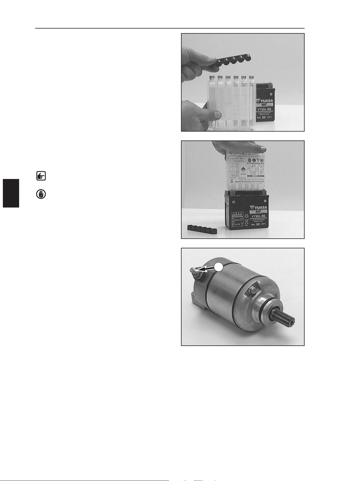
ELECTRIC SYSTEM
F
2
FILLING THE BATTERY
–Take the battery and electrolyte container out of the
packing.
Read the instructions for use carefully before you fill
the battery.
– Remove the cover from the electrolyte container.
– Insert the electrolyte container in the openings in the
battery and press down firmly.
– When all of the chambers in the electrolyte container
are drained, pull the container off of the battery.
–Tightly close the openings in the battery with the
cover.
NOTE: after filling, let the battery rest for at
least 1/2 hour without charging.
WARNING: follow the instructions provided on
the package insert enclosed with each new
battery before you fill a new battery. The insert
also provides safety regulations.
Non-compliance with the safety regulations can
cause severe injuries.
CHECKING THE STARTER ENGINE
–Disconnect the negative pole from the battery and
dismount the starter.
– Connect the negative pole of a 12-V battery to the
starter engine housing and the briefly connect the
positive pole of the battery to the starter connector (1)
(use thick cables).
– The starter engine should turn when the circuit is
closed.
– If not, the starter needs to be replaced.
1
Page 72
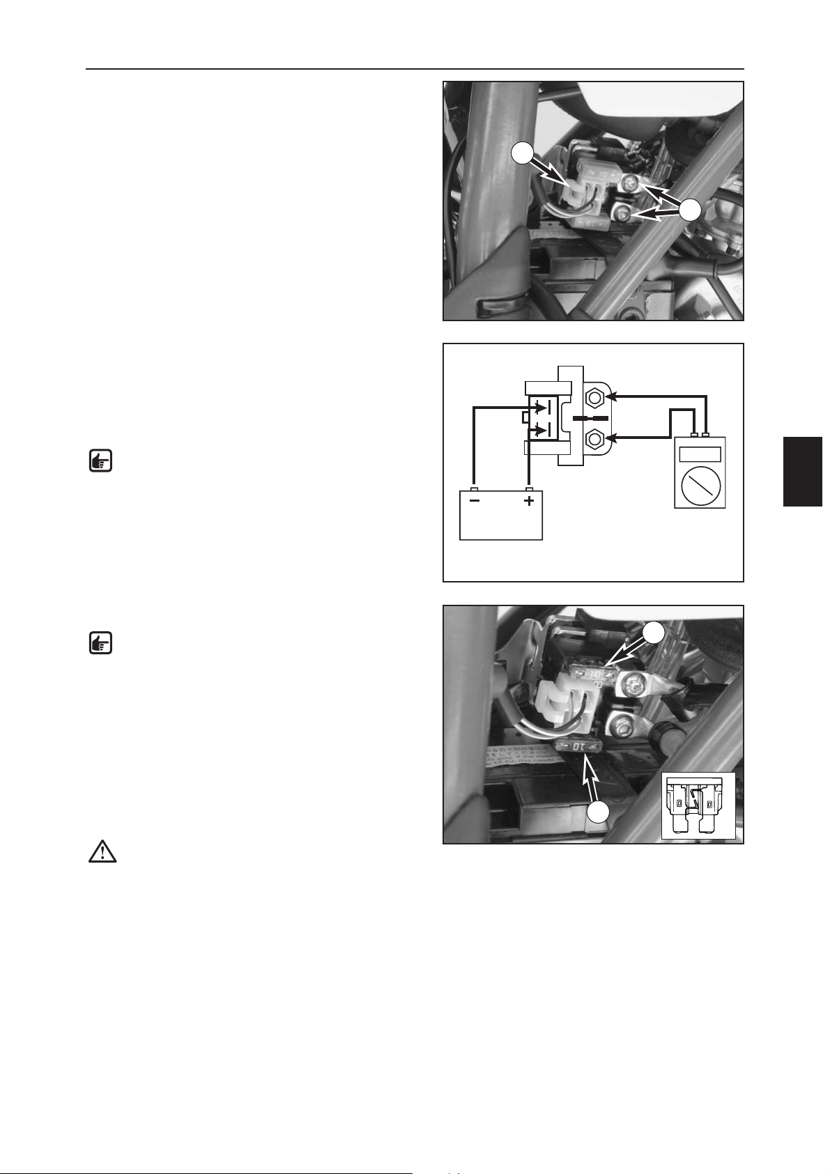
ELECTRIC SYSTEM
F
3
CHECKING THE STARTER RELAY
– Unscrew the brake fluid reservoir for the foot brake
and let it hang down on the side.
– Unscrew the negative pole from the battery and the
two cables (1) from the starter relay.
– Pull the connector (2) from the starter relay and
remove the starter relay from the support.
–Connect the starter relay to a 12-V battery as shown in
the drawing.
– Use an ohmmeter to check the continuity between the
screw connections.
Reading: 0 Ω OK
Reading: ∞Ωdefective
NOTE: you should hear a click when you switch
the starter relay.
– The starter relay is mounted in the reverse order.
MAIN FUSE
NOTE: the main fuse (3) 10 A is located in the
starter relay. It supplies the following power
consumers:
–Starter system
– Horn
–Turn signal
– Multifunctional digital speedometer
The fuse (4) is a spare fuse.
– Pull out the fuse and replace with a new fuse. Mount
the cover again.
CAUTION: never use a stronger fuse or a
repaired fuse. Improper use can destroy the
entire electric system.
– If you use the spare fuse on the road, be sure to
replace it at the next opportunity.
1
2
3
4
Page 73
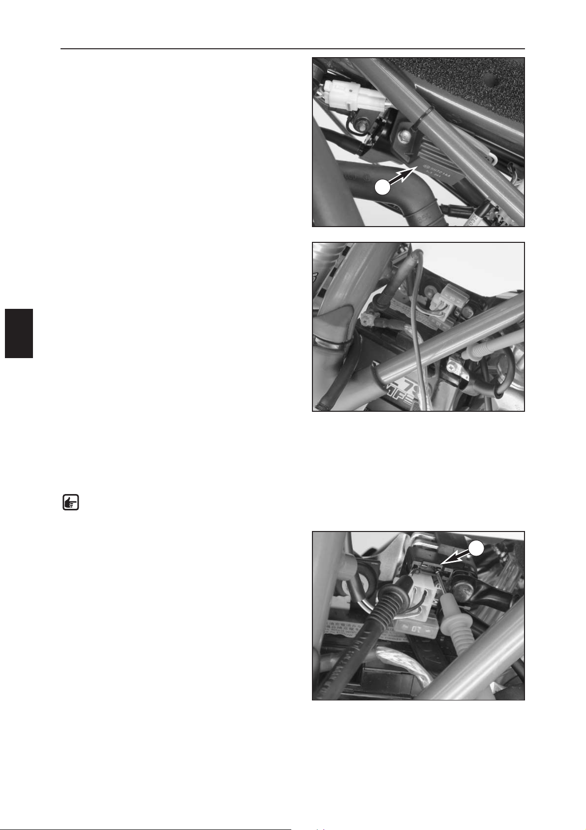
ELECTRIC SYSTEM
F
4
CHECKING THE VOLTAGE REGULATOR
A defective voltage regulator (1) can have the following
effect:
– No voltage in the circuit In this case, disconnect the
voltage regulator with the engine at idle speed. If the
consumers run, the voltage regulator is defective.
If there is still no voltage, the error must be in the
switch, the wiring harness or in the ignition system.
– Excessive voltage in the circuit
Bulbs burn out. In this case the voltage regulator
needs to be replaced.
DYNAMIC GENERATOR VALUES - KOKUSAN
4K-3B
Measuring conditions:
–All plugs and the ground connection are in a non-
corroding condition, plugs are tightly connected
– The battery is in a startable condition, not fully
charged (start several times if the battery is fully
charged)
–Start the engine; the measurement must be taken right
after starting
Controller output – measure the voltage with the
measuring tips of the peak voltage adapter directly on
the poles of the vehicle battery:
– Unstressed (no electric consumer switched on), engine
running at idle speed (1400 +/- 50 rpm)
Multimeter reading: 13 volts +/- 0.5 volt
– Stressed (light switched on, horn and brake actuated),
engine running at idle speed
Multimeter reading: 13 volts +/- 0.5 volt
– Stressed (light switched on, horn and brake actuated),
engine running at increasing speed (- 8000 rpm)
Multimeter reading: 13 volts +/- 0.5 volt
NOTE: the black measuring tip on the peak
voltage adapter should be applied to the
ground (negative pole).
Check the charge current – remove the main fuse, apply
the multimeter measuring tips (without the peak voltage
adapter) to both plugs on the fuse carrier (2) and
measure the current (set the multimeter DCA to 10
amperes):
– Unstressed (no electric consumer switched on), engine
running at idle speed
Multimeter reading: 1.5 amperes +/- 0.2 ampere
– Stressed (horn actuated), engine running at idle speed
Multimeter reading: -1.0 ampere +/- 0.2 ampere
– Stressed (horn actuated), engine running at increasing
speed
Multimeter reading: 0.8 ampere +/- 0.2 ampere
1
2
Page 74

ELECTRIC SYSTEM
F
5
TROUBLESHOOTING IN THE IGNITION SYSTEM
Before checking the ignition, make sure:
– The emergency OFF switch is in the ON position
– The battery is charged
– The main fuse is OK
Check whether there is an ignition spark upon starting:
– Pull off the spark plug connector.
–Disconnect the spark plug connector from the ignition wire
– Hold the loose end of the ignition wire approx. 5 mm from the ground.
–A strong spark should be visible when the starter is actuated. If the battery is nearly run down, turn off the light
and use the kickstarter.
– If a spark is visible, mount the spark plug connector again.
– Unscrew the spark plug and insert in the spark plug connector.
– Hold the spark plug against the ground. A strong spark should be visible at the electrode when the starter is
actuated. If not, the spark plug connector or spark plug is defective.
If no spark is visible during the first test, check the following parts:
–Emergency OFF switch
– Cable tree parts belonging to the emergency OFF switch.
If the ignition is being supplied with voltage but no spark is visible, check:
–The ground connection from the CDI unit and ignition coil
– The cable from the CDI unit to the ignition coil
– The pulse generator
– The stator
– The ignition coil
– The short-circuit button
NOTE: the CDI unit cannot be tested with simple devices. It can only be tested on an ignition test
stand.
Page 75
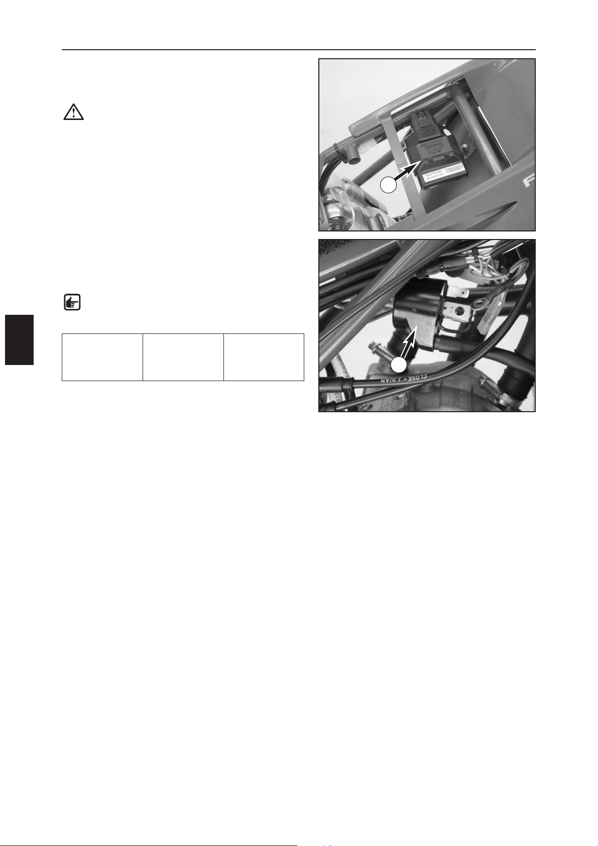
ELECTRIC SYSTEM
F
6
CDI UNIT
Check the cables and socket connections to the CDI unit.
The CDI unit can only be tested on an ignition test stand.
CAUTION: never test the CDI unit with a
conventional measuring device. Highly sensitive
electronic components could be destroyed.
CHECKING THE IGNITION COIL
– Disconnect the ignition coil and remove the spark plug
connector.
–Use an ohmmeter to take the following measurements:
NOTE: the following measurements only
correspond to the setpoint values at a coil
temperature of 20° C.
Replace the ignition coil if the measured values deviate
significantly from the setpoint value.
Measurement Cable colors Resistance
Primary coil blue/white-ground
0,30 Ω ± 0,05 Ω
Secondary coil
blue/white ignition wire
6,30 kΩ ± 1,26 kΩ
1
2
Page 76
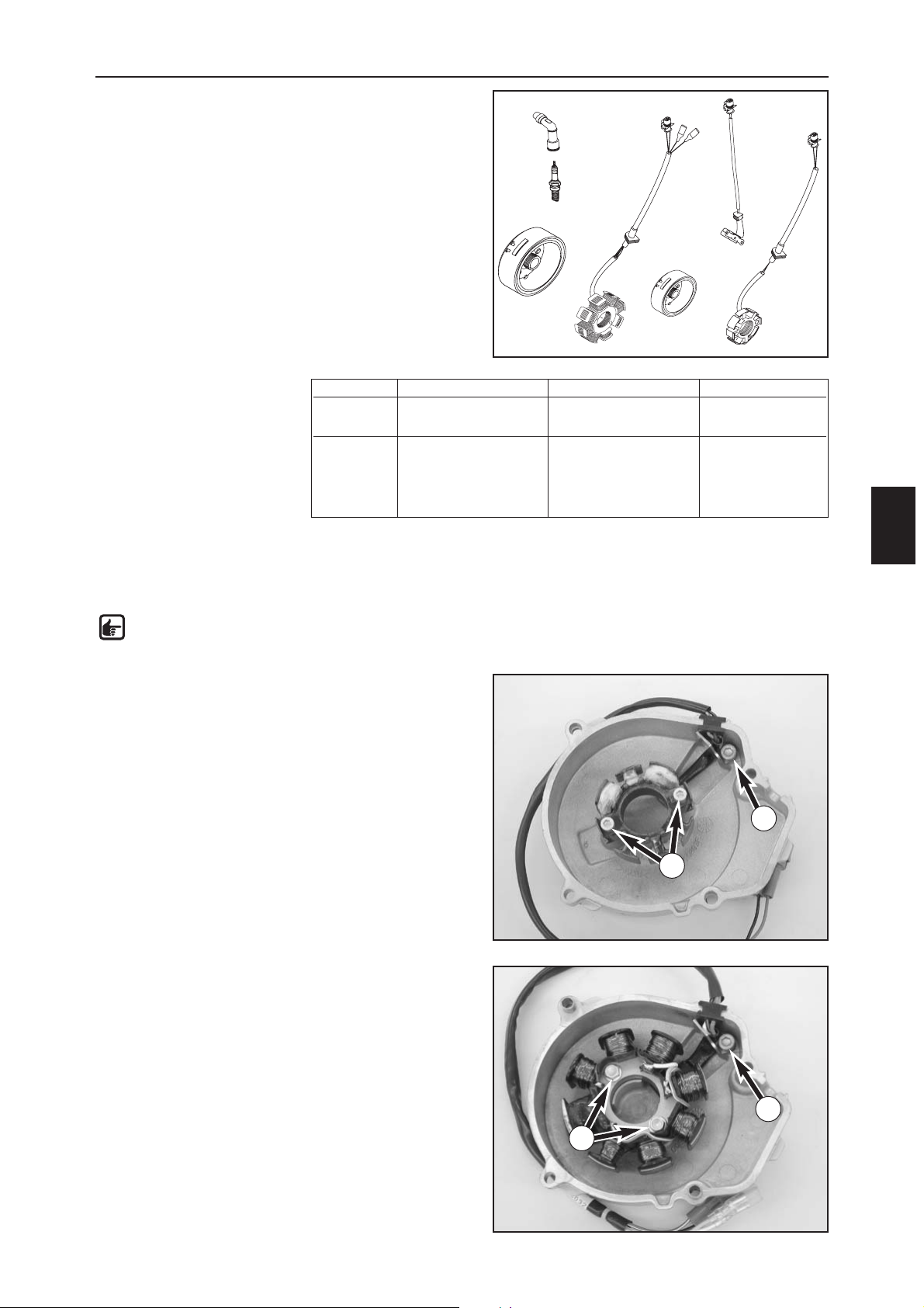
ELECTRIC SYSTEM
F
7
IGNITION SYSTEM
General information
The measurements described below will only detect
serious defects.
Short circuits in the coil that lead to a weak ignition spark
or poor generator capacity can only be established on an
ignition test stand.
In case of a defect, check the cable and the plug and
socket connections in the ignition system first.
Always pay attention to the right measuring range for the
digital multimeter when measuring
CHECKING THE STATOR AND PULSE
GENERATOR
Use an ohmmeter to perform the following
measurements:
NOTE: the measurements must be performed
at a temperature of 20° C, otherwise the
readings will deviate significantly.
Replace the stator if one of the measured
values deviates significantly from the setpoint
value.
REPLACING THE STATOR IN THE FC
MODELS (4K-3A)
– Remove bolt (1) and the retaining bracket.
–Remove the 2 bolts (2) and take the stator out of the
ignition cover.
–Place a new stator in the ignition cover.
–
Degrease the thread of all 3 bolts and apply Loctite 243.
– Mount the bolts and tighten to 6 Nm.
– Run the wiring harness stress free and fix with the
retaining bracket. Don't forget the cable socket.
REPLACING THE STATOR IN THE FE AND
FS MODELS (4K-3B)
–Remove the bolt (3) and the retaining bracket.
–Remove the 2 bolts (4) and take the stator out of the
ignition cover.
–Place a new stator in the ignition cover. Degrease the
thread of all 3 bolts and apply Loctite 243.
– Mount the bolts and tighten to 8 Nm.
– Run the wiring harness stress free and fix with the
retaining bracket.
Ignition Measurement Cable colors Resistance
4K-3A Pulse generator coil red – green 100 Ω
± 20 Ω
Stator black/red – red/white 26 Ω ± 5,2 Ω
4K-3B Pulse generator coil red – green 100 Ω
± 20 Ω
Stator black/red – red/white 15 Ω ±3 Ω
Charging coil ground – yellow 0,65 Ω ±0,15 Ω
white – yellow 0,16 Ω ±0,03 Ω
1
2
3
4
Page 77
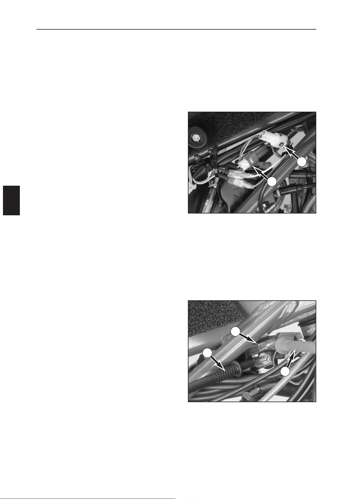
ELECTRIC SYSTEM
F
8
Check the pulse generator for an output signal – bipolar
plug (1) with green and red cable colors (also see circuit
diagram on opposite page):
– Apply the red measuring tip of the peak voltage
adapter to the green cable and the black measuring
tip to the red cable, disconnect plug (1) to disconnect
the CDI unit (2).
Multimeter reading: 6 volts +/- 0.5 volt
– Same measurement with CDI unit connected
Multimeter reading: 4 volts +/- 0.5 volt
Check the generator charging coil for the ignition
capacitor charge for output voltage – bipolar plug (3)
with black/red and red/white cable colors (also see circuit
diagram on opposite page).
– Apply the red measuring tip of the peak voltage
adapter to the black/red cable and the black
measuring tip to the red/white cable; disconnect plug
(3) to disconnect the CDI unit (2).
Multimeter reading: 35 volts +/- 5 volts
– Same measurement with CDI unit connected.
Multimeter reading: 210 volts +/- 10 volts
Check the primary voltage output (4) for ignition coil
control (also see circuit diagram on opposite page) for
output voltage (blue/white cable).
– Apply the red measuring tip (R) of the peak voltage
adapter to the black/white cable (ground) and the
black measuring tip (S) to the blue/white cable, CDI
unit (2) and ignition coil (5) connected.
Multimeter reading: 200 volts +/- 10 volts
STATIC IGNITION VALUES - KOKUSAN 4K-3A, B
Measuring conditions:
– Cold engine
– Seat and tank removed
–All plugs and the ground connections are in a non-corroding condition, plugs are tightly connected
– Battery charged (if installed) and the light switch turned off
–Gap between the rotor and the pulse generator is set to 0.75 mm
– Decompression lever is pulled
– Depress the kickstarter forcefully at least 5 times for each measurement
1
3
4
R
S
Page 78
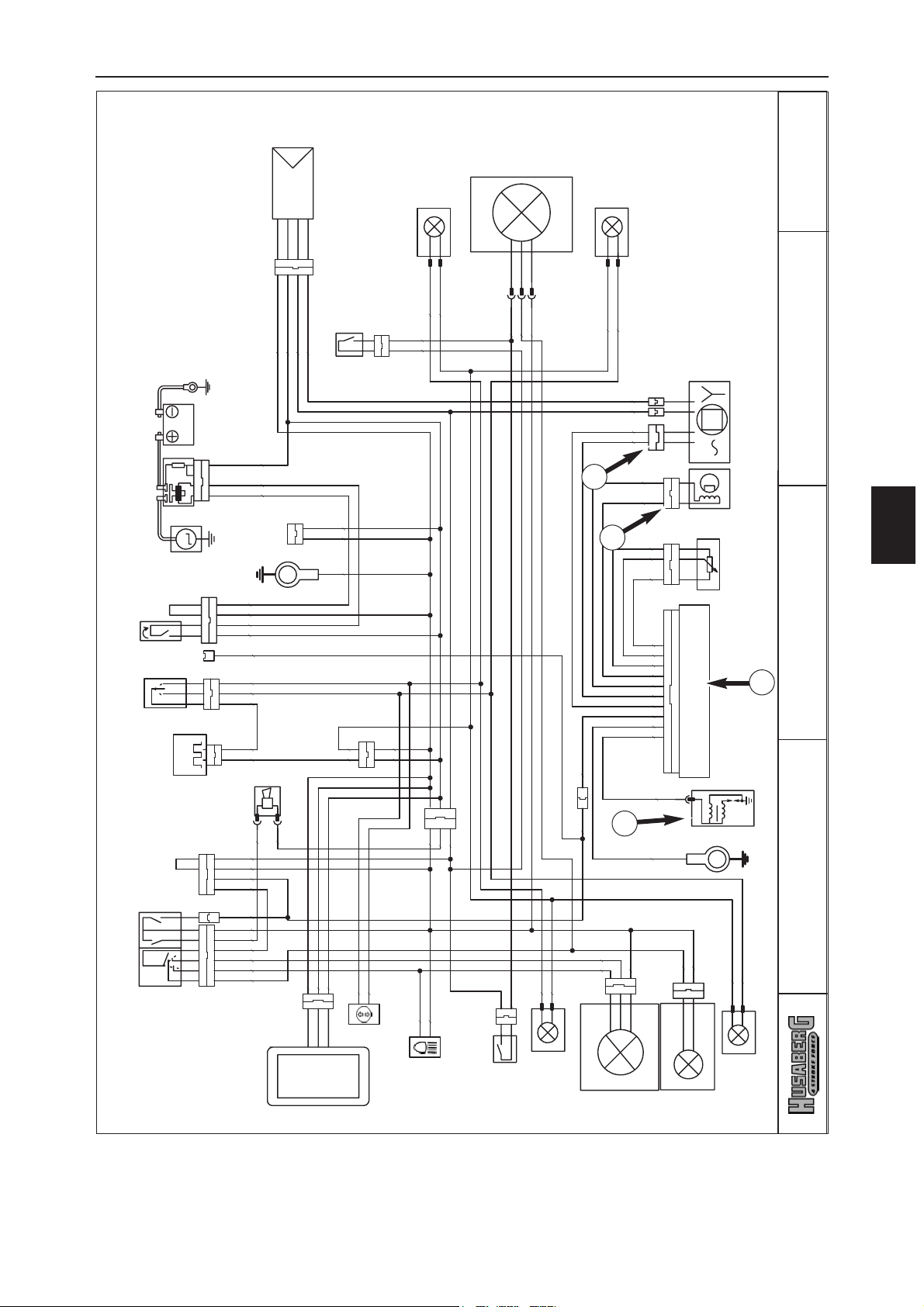
ELECTRIC SYSTEM
F
9
1
2
3
5
U
regulator-rectifier
right rear flasher
bl
br
br
bl
br
wh-re
ye-re
bl
pu
or
or
ye-re
ye-re
wh-re
bl
ye-bl
A
10
start relay battery
M
starter motor
black
start bottom
flasher switch
G
flasher relay
rear
wh
ye
ye-re
brake switch
ye-re
cooling fan
br
br
br
ye-re
wh-gn
ye
br
ye-re
gn-wh
rear light/brakelight
24.03.2003
left rear flasher
pu
wh
br
br
800.11.075.150
800.11.078.000
wh
ye
re-wh
re-bl
gn
re
G
generator
3
main harness
light connector
pick up
bl
ye
bu
bu
ye
bl
re
gn
re-bl
re-wh
ye-bl
br
bu-wh
TPS
I
D
wiring diagramm
C
br
bl-wh
br
headlightposition light
ignition coil
wh
br
pu
br
left front flasher
Husaberg FE 04
horn
ye-re
re
ye
ye
ye-bl
br
ye-bl
br
stop buttonhorn switch
high/low beam switch
re
ye
gn
bu
wh
br-bl
ye-re
br
bl
pu
multi-func.-digital-speedometer
br
ye
ye-re
wh-gn
bu
br
flasher control lamp
driving light lamp
ye
brake switch
front
ye-bl ye-bl
gn
bu
bl
br
right front flasher
Page 79
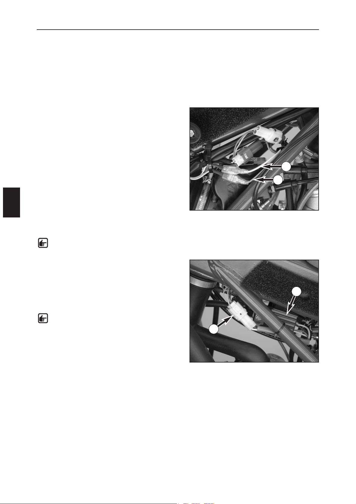
ELECTRIC SYSTEM
F
10
Check the generator outlet (also see circuit diagram on
opposite page) for voltage between the following cable
colors:
– Between yellow and brown (ground), plug (7)
disconnected
Multimeter reading: 12 volts +/- 1 volt
– Same measurement with plug (7) connected
Multimeter reading: 12 volts +/- 1 volt
– Between white and brown (ground), plug (8)
disconnected
Multimeter reading: 19 volts +/- 1 volt
– Same measurement with plug (8) connected
Multimeter reading: 15 volts +/- 1 volt
NOTE: apply the black measuring tip on the
peak voltage adapter to the ground.
Check the regulator output voltage (9) (also see circuit
diagram on opposite page) with the cable color
yellow/red, controller (10) connected, fuse (11) removed:
– Between yellow/red and brown (ground)
Multimeter reading: 14 volts +/- 1 volt
NOTE: apply the black measuring tip on the
peak voltage adapter to the brown (ground)
cable.
STATIC GENERATOR VALUES - KOKUSAN 4K-3B
Measuring conditions:
– Cold engine
– Seat and tank removed
–All plugs and the ground connections are in a non-corroding condition, plugs are tightly connected
– Battery charged (if installed) and the light switch turned off
– Decompression lever is pulled
– Depress the kickstarter forcefully at least 5 times for each measurement
7
8
9
10
Page 80
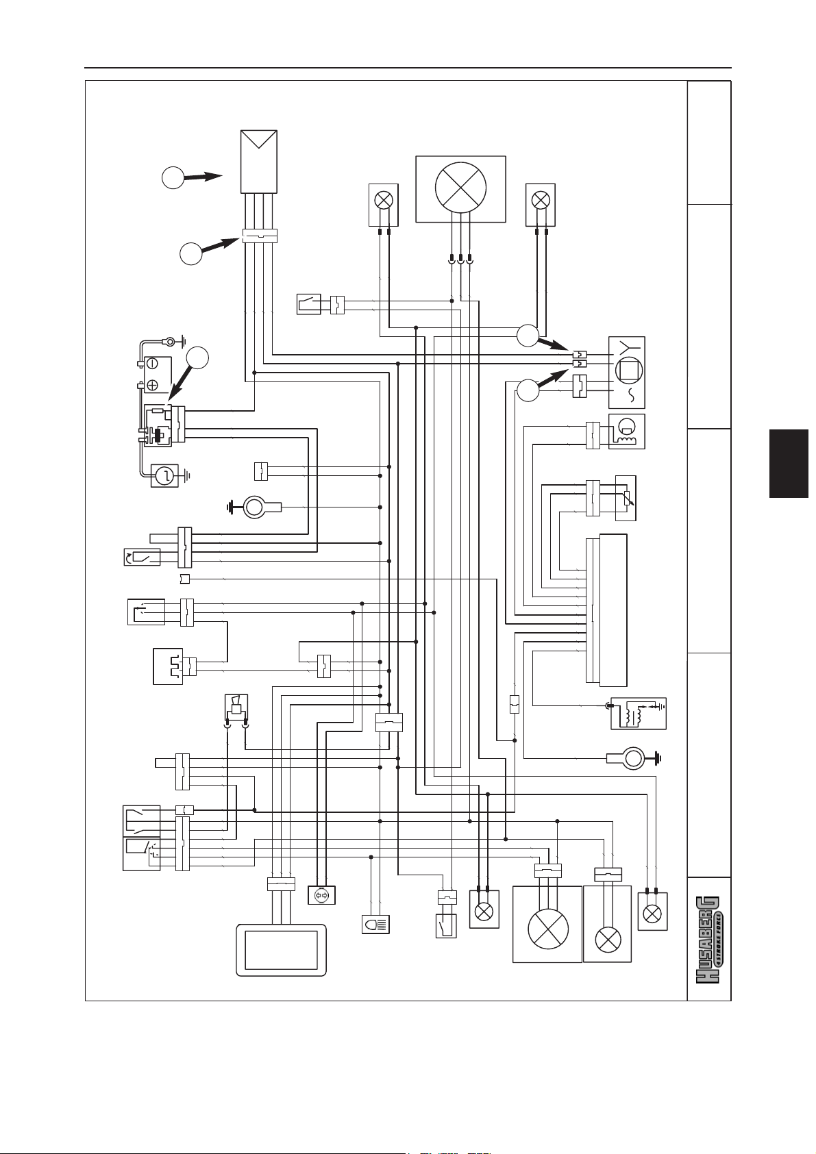
ELECTRIC SYSTEM
F
11
7
8
9
10
11
U
regulator-rectifier
right rear flasher
bl
br
br
rear
wh
ye
ye-re
brake switch
wh-gn
ye
bl
br
wh-re
ye-re
bl
pu
or
or
ye-re
ye-re
wh-re
bl
ye-re
cooling fan
ye-bl
br
br
br
br
ye-re
ye-re
A
10
start relay battery
M
starter motor
black
start bottom
flasher switch
G
flasher relay
gn-wh
rear light/brakelight
24.03.2003
left rear flasher
pu
wh
br
br
800.11.075.150
800.11.078.000
wh
ye
re-wh
re-bl
gn
re
G
generator
3
main harness
light connector
pick up
bl
ye
bu
bu
ye
bl
re
gn
re-bl
re-wh
ye-bl
br
bu-wh
TPS
I
D
wiring diagramm
C
br
headlightposition light
bl-wh
ignition coil
br
wh
br
pu
br
left front flasher
Husaberg FE 04
horn
ye-re
re
ye
ye
ye-bl
br
ye-bl
br
stop buttonhorn switch
high/low beam switch
re
ye
gn
bu
wh
br
br-bl
ye-re
bl
pu
multi-func.-digital-speedometer
br
ye
ye-re
wh-gn
bu
br
flasher control lamp
driving light lamp
ye
brake switch
front
ye-bl ye-bl
gn
bu
bl
br
right front flasher
Page 81

Page 82
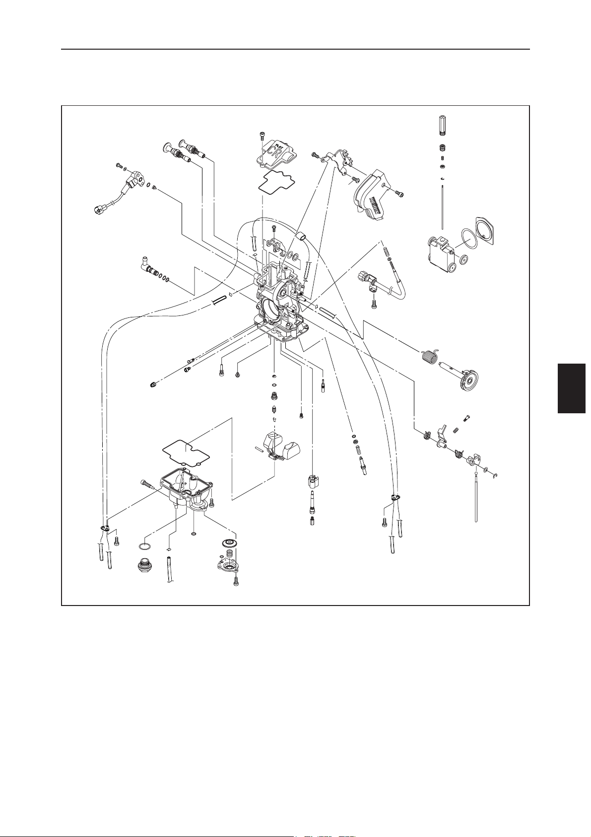
FUEL SYSTEM
G
1
KEIHIN FCR-MX 39/41 CARBURETOR
Page 83
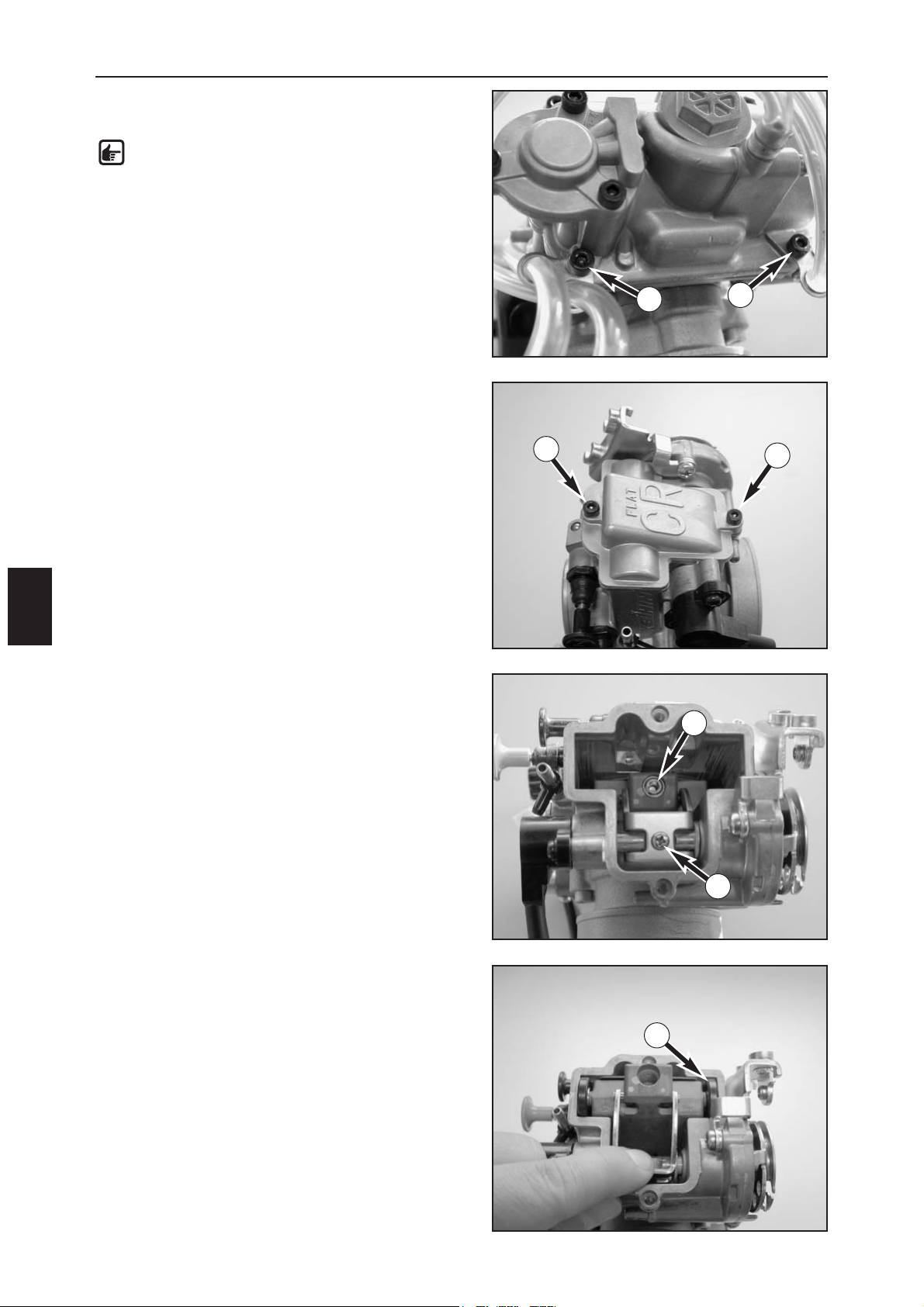
FUEL SYSTEM
G
2
DISASSEMBLING THE KEIHIN FCR-MX 39/41
CARBURETOR
NOTE: Before you start to disassemble the
carburetor, make sure your workplace is clean
and offers enough room to spread out the
individual carburetor parts.
–
Dismount the carburetor and remove any accumulated dirt.
–
Loosen the 2 screws (1) and disconnect all of the vent
hoses from the carburetor.
–
Remove the 2 screws (2) and lift the slide cover and gasket
from the carburetor.
–
Remove the screw (3) and pull the jet needle from the
throttle slide.
–
Remove screw (4).
–
Lift the throttle slide arm and take the throttle slide
including the roller (5) and slide shim out of the carburetor.
1
1
2
2
3
4
5
Page 84
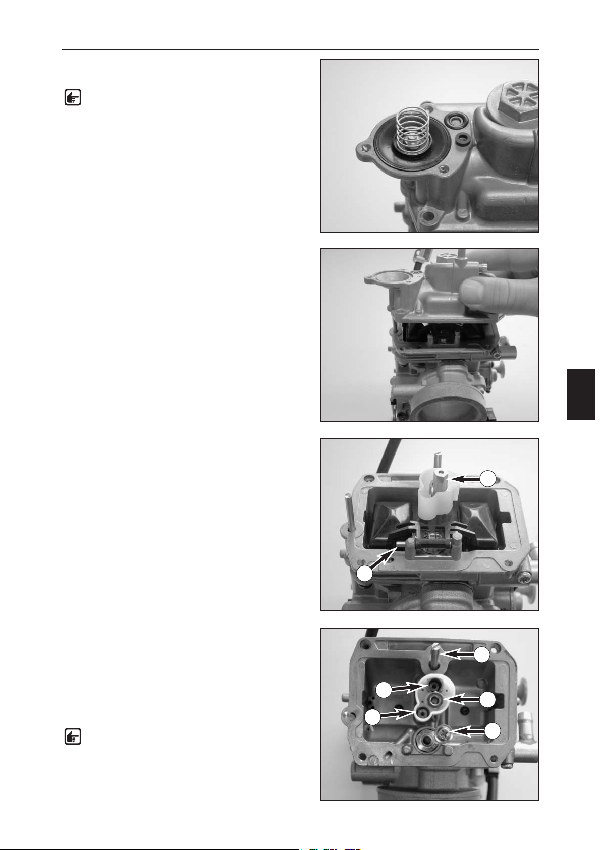
FUEL SYSTEM
G
3
–Turn the carburetor around, remove the 3 screws and
remove the cover on the accelerator pump.
NOTE: When dismounting the cover, pay
special attention to the spring and seal rings
since they are easily lost.
–Take the 2 seal rings, spring and membrane out of the
pump housing.
– Remove the screws from the float chamber and lift off
the float chamber.
– Pull out the float hinge pin (1) and remove the float
together with the float needle valve.
– Remove the main jet (2).
– Remove the screw (3) and carefully pull the float
needle valve seat out of the carburetor with pliers.
– Unscrew the idling jet (4), starting jet (5) and needle
jet (6).
– Screw in the mixture control screw (7) up to the stop,
counting and writing down the number of turns.
– Unscrew the mixture control screw and remove
together with the spring, washer and O-ring.
NOTE: The spring, washer and O-ring usually
stay in the hole. You can remove these parts
with compressed air.
2
1
7
6
3
5
4
Page 85
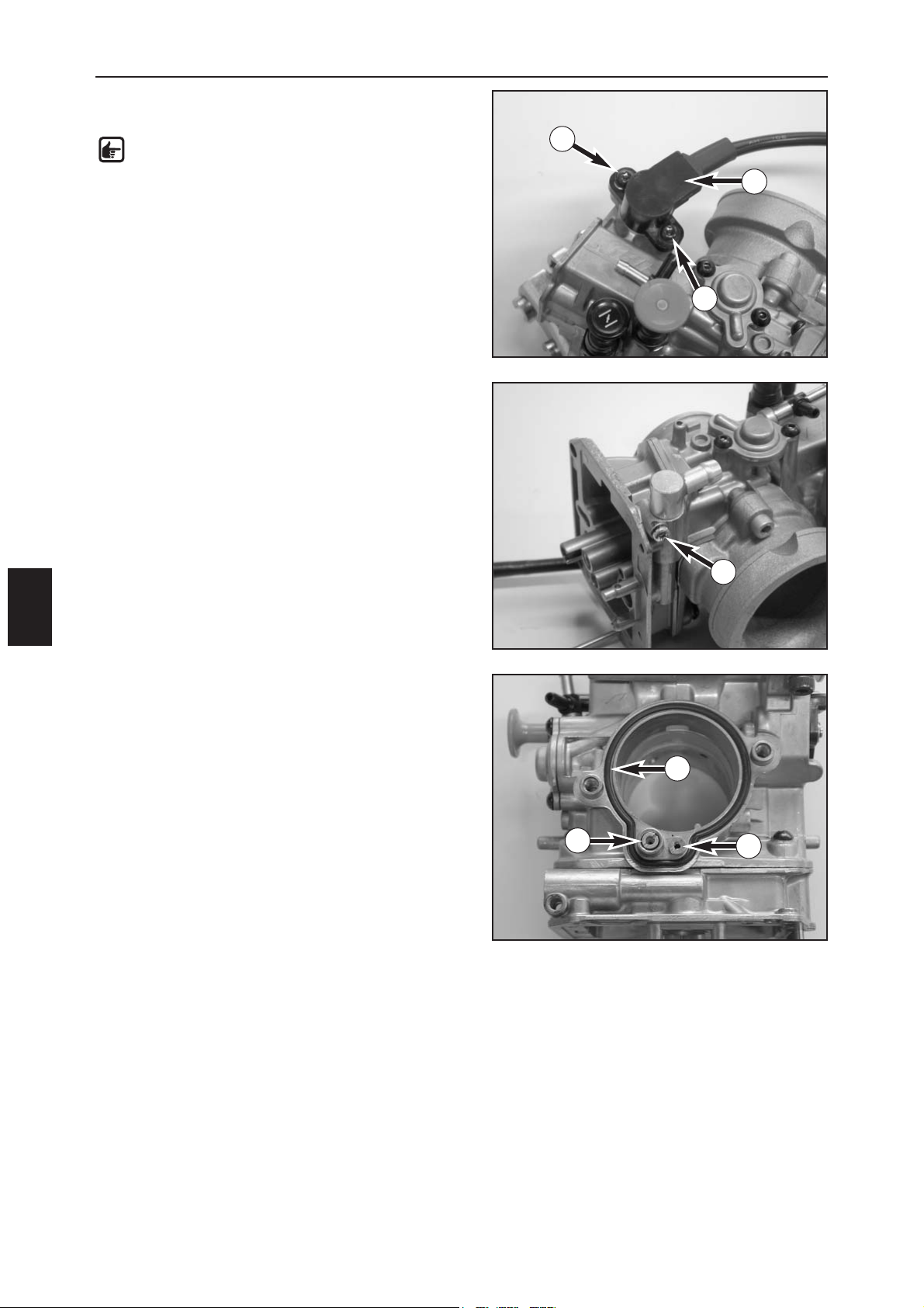
FUEL SYSTEM
G
4
– Remove the screws (1) with special tool
800.29.052.000 and take off the throttle sensor (2).
NOTE: Only remove the throttle sensor if it is
defective. The throttle sensor must be
readjusted if the screws (1) are loosened.
– Remove the screw (3) and pull the connecting piece
out of the carburetor.
– Remove the 2 screws and take the intake trumpet and
the O-ring (4) off of the carburetor.
– Unscrew the idle-air jet (5) and main air jet (6).
– Thoroughly clean all of the jets and the other parts
and blow through with compressed air.
–Clean the carburetor housing and blow compressed
air through all of the ducts in the carburetor.
– Check all of the gaskets for damage and replace if
necessary.
1
1
2
3
4
5
6
Page 86
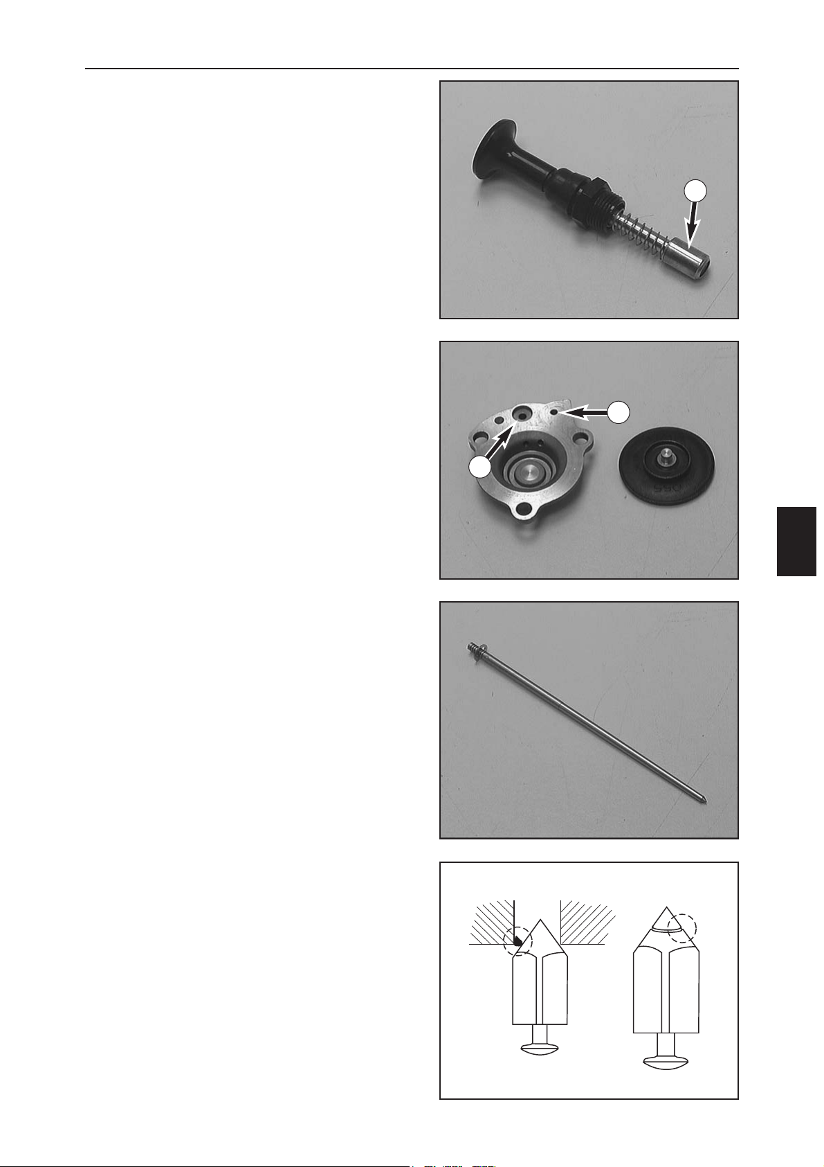
FUEL SYSTEM
G
5
CHECKING THE CHOKE SLIDE AND THE
HOT START KNOB
Choke slide:
The choke slide must be easily actuated.
The piston (1) on the choke slide may not have any deep
scores or deposits.
Hot start knob:
The hot start knob must be easily actuated.
The piston on the hot start knob may not have any deep
scores or deposits.
CHECKING THE ACCELERATOR PUMP
Check the diaphragm for crack formation or brittleness.
Check the gaskets for damage.
Check the holes (2) for free passage.
CHECKING THE JET NEEDLE
Check the jet needle for deformation and wear.
CHECKING THE FLOAT NEEDLE VALVE
Check the needle valve for indentations around the
sealing area.
Make sure no dirt has accumulated between the valve
seat and the float needle.
1
2
2
Page 87
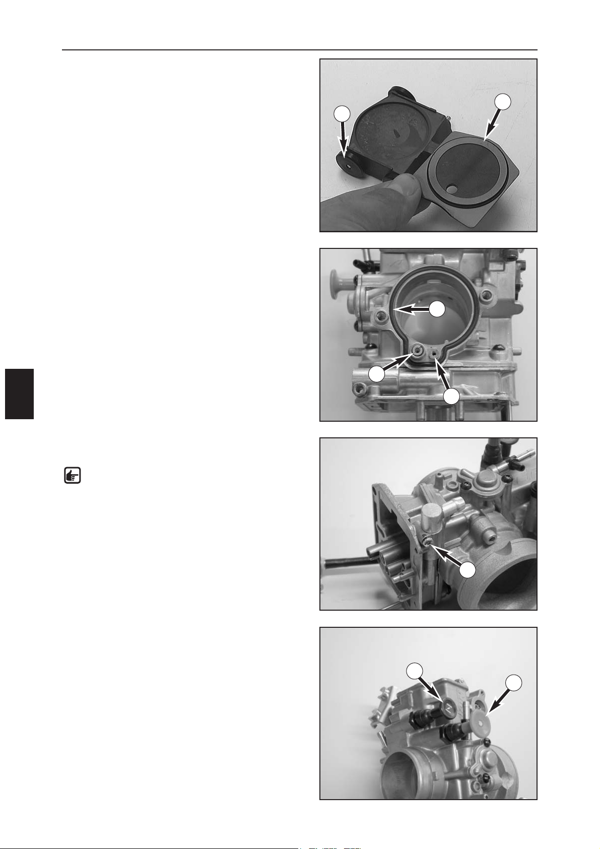
FUEL SYSTEM
G
6
CHECKING THE THROTTLE SLIDE
The rollers (1) on the throttle slide should be easy to turn
and not have any flat areas.
Check the throttle slide shim (2) for damage.
ASSEMBLING THE KEIHIN FCR-MX 39/41
CARBURETOR
– Mount the idle-air jet (3) and the main air jet (4).
–Place the O-ring (5) in the groove and attach the intake
trumpet to the carburetor with the 2 screws.
– Insert the fuel connection in the carburetor and fix with
the screw (6).
NOTE: The connecting piece should be easy to
turn when mounted.
– Mount and actuate the choke slide (7) and the hot start
knob (8) several times, checking for smooth operation.
Also make sure that the choke and the hot start knob
lock properly.
1
2
3
4
5
6
7
8
Page 88
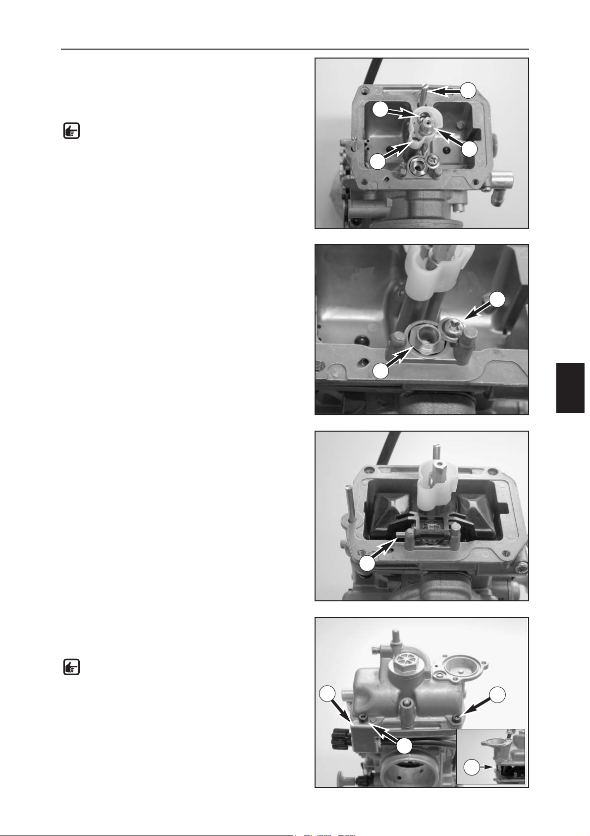
FUEL SYSTEM
G
7
– Mount the spring, washer and the O-ring on the
mixture control screw (1) and turn the mixture control
screw all the way in to the stop.
–Now unscrew the mixture control screw the number of
turns written down during disassembly.
NOTE: Basic carburetor setting: see Technical
specifications.
– Mount the idling jet (2), starting jet (3) and needle jet
together with the main jet (4).
– Insert the needle valve seat (5) in the hole and fix with
the screw (6).
– Position the float and the float needle valve and mount
the float hinge pin (7).
– Check the float level (see page G13).
– Mount the float chamber together with the gasket,
position the attachment for the adjusting screw (8) and
fix the float chamber with the screws (9).
NOTE: When mounting the float chamber, make
sure that the push rod (10) on the accelerator
pump slides into the hole.
1
2
3
4
5
6
10
7
9
9
8
Page 89
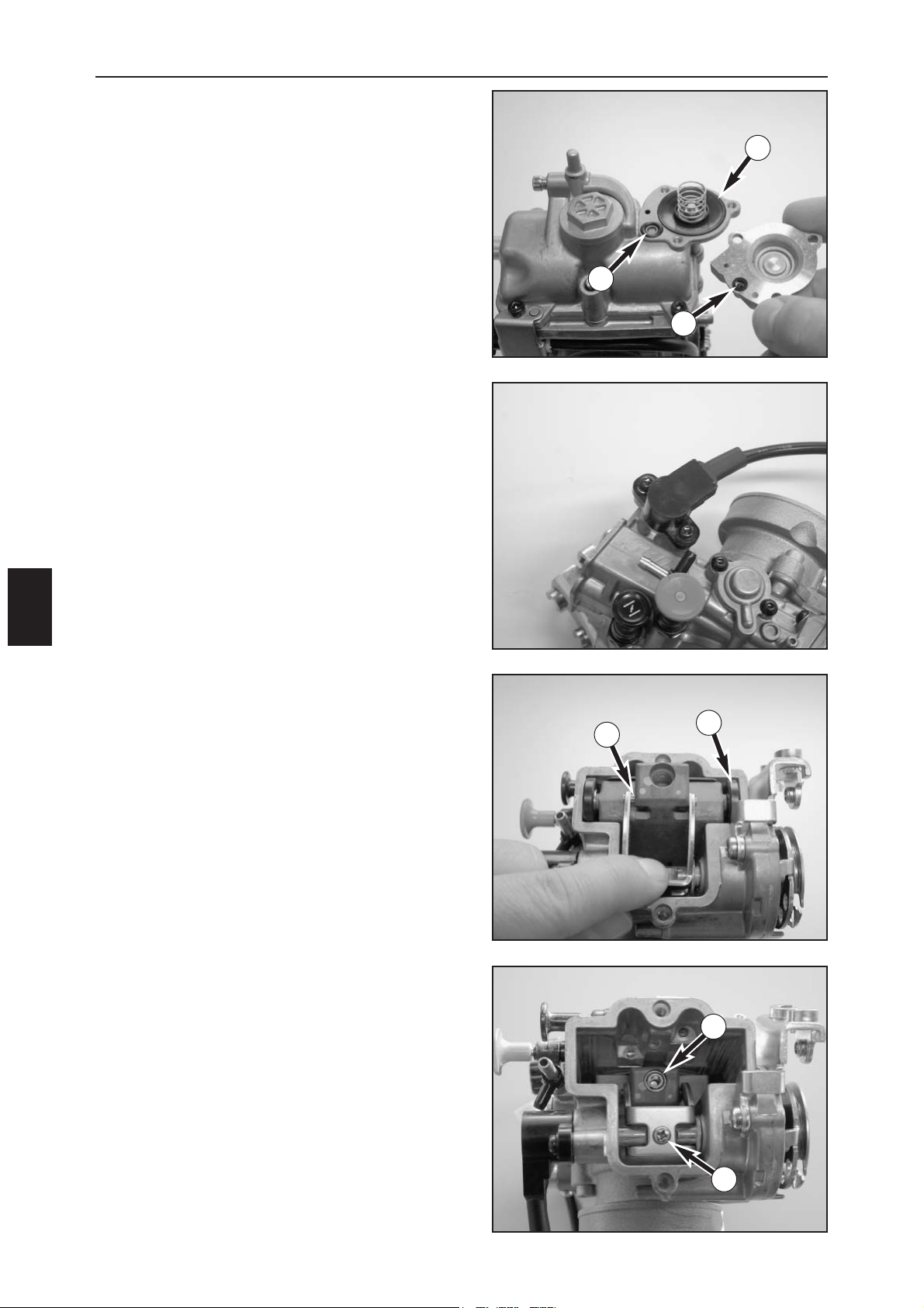
FUEL SYSTEM
G
8
–Place the spring and the diaphragm (1) in the pump
housing with the inscription facing up.
–Place the O-ring (2) in the groove. Fix the seal ring (3)
in the cover with a little grease and fasten the cover
with the 3 screws.
–Mount the throttle sensor so that the flat part of the
carburetor engages in the groove in the throttle
sensor, tighten the screws with special tool
800.29.052.000.
–Lift up the throttle slide arm and slide the throttle
slide, the roller (4) and the slide shim into the
carburetor so that the rollers (5) engage in the throttle
slide (see photo).
– Check the throttle slide for smooth operation.
– Apply Loctite 243 to the screw (6) and tighten.
– Mount the jet needle and fix with the screw (7).
1
2
3
4
5
6
7
Page 90
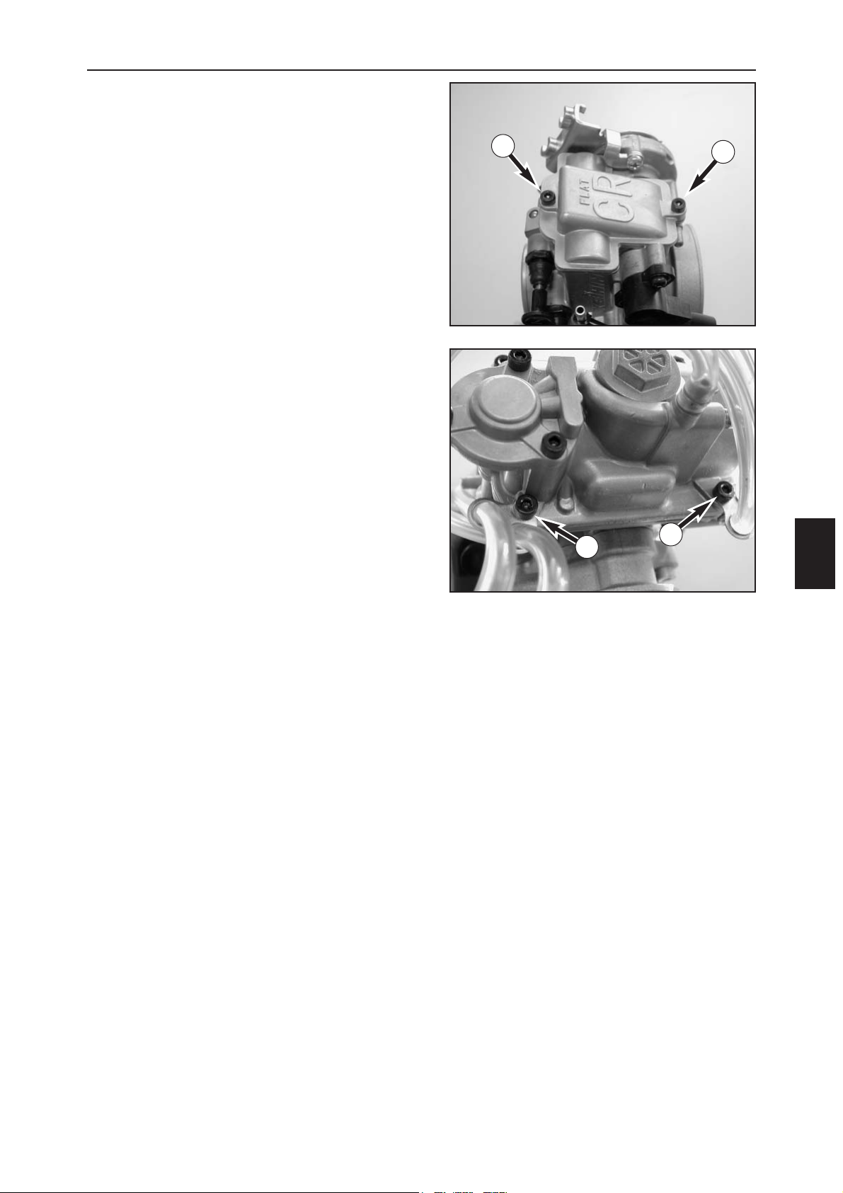
FUEL SYSTEM
G
9
– Position the slide cover with the gasket and fasten with
the 2 screws (1).
–Attach the vent hoses to the float chamber with the 2
screws (2).
1
1
2
2
Page 91
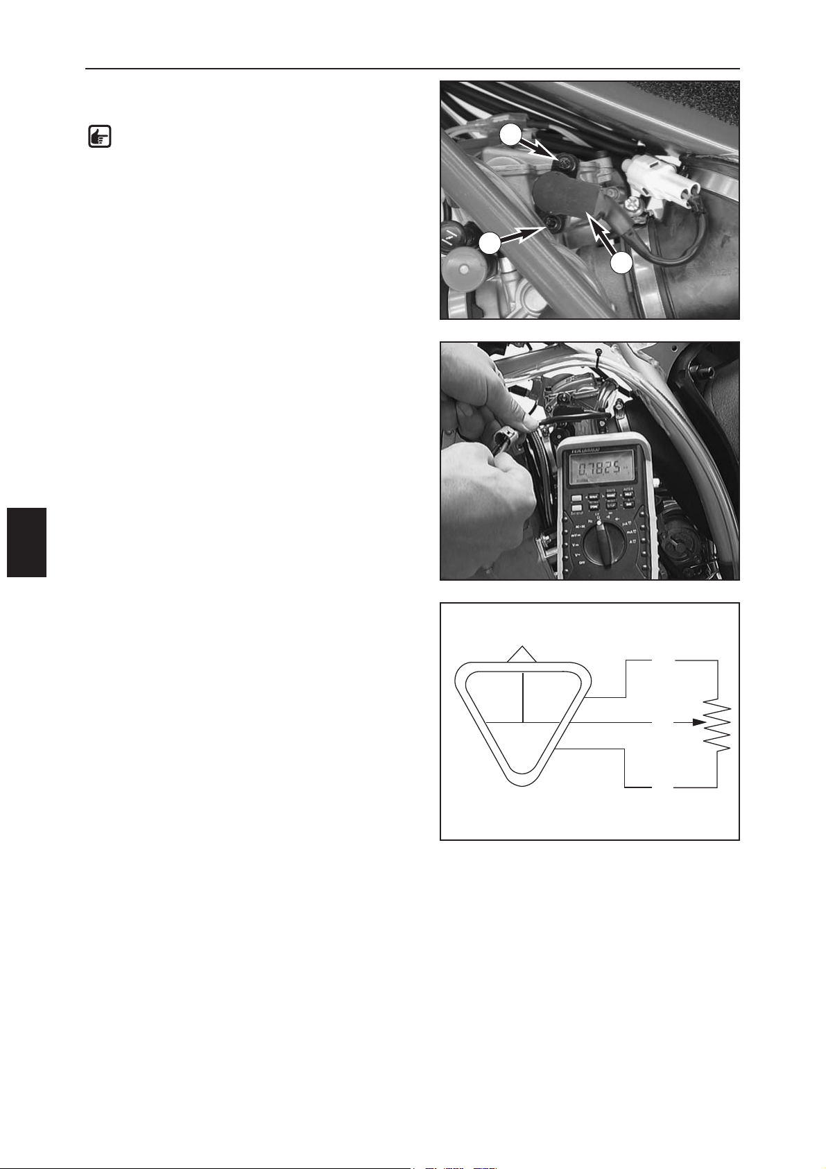
FUEL SYSTEM
G
10
ADJUSTING THE POSITION OF THE
THROTTLE SENSOR
NOTE: The idle speed must be correctly
adjusted before you check the position of the
throttle sensor.
–Disconnect the plug and socket connection on the
throttle sensor.
– Connect a multimeter (measuring range Ω x 1k) to the
blue (+) and the black (–) cable on the throttle sensor
and measure the throttle resistance.
– Multiply this value by 0.15 to obtain the setting for the
throttle sensor.
Example:
Throttle sensor resistance (bl/b) = 5 kΩ
Throttle sensor resistance (y/b) = 5 kΩ x 0,15 =
750 Ω ± 50 Ω
– Connect the multimeter (measuring range Ω x 100) to
the yellow (+) and the black (–) cable on the throttle
sensor and measure the throttle sensor resistance with
the throttle grip closed.
According to the above example, this value should be
750 Ω ± 50 .
– If the measured value does not correspond to the
setpoint value, loosen the 2 screws (1) and turn the
throttle sensor (2) until the measuring device displays
the setpoint value.
–Fix the throttle sensor in this position by tightening the
screws and check the value again.
– Connect the throttle sensor to the cable tree.
1
1
2
bu
bu
ye
ye
bl
bl
bu = blue
ye = yellow
bl = black
Page 92
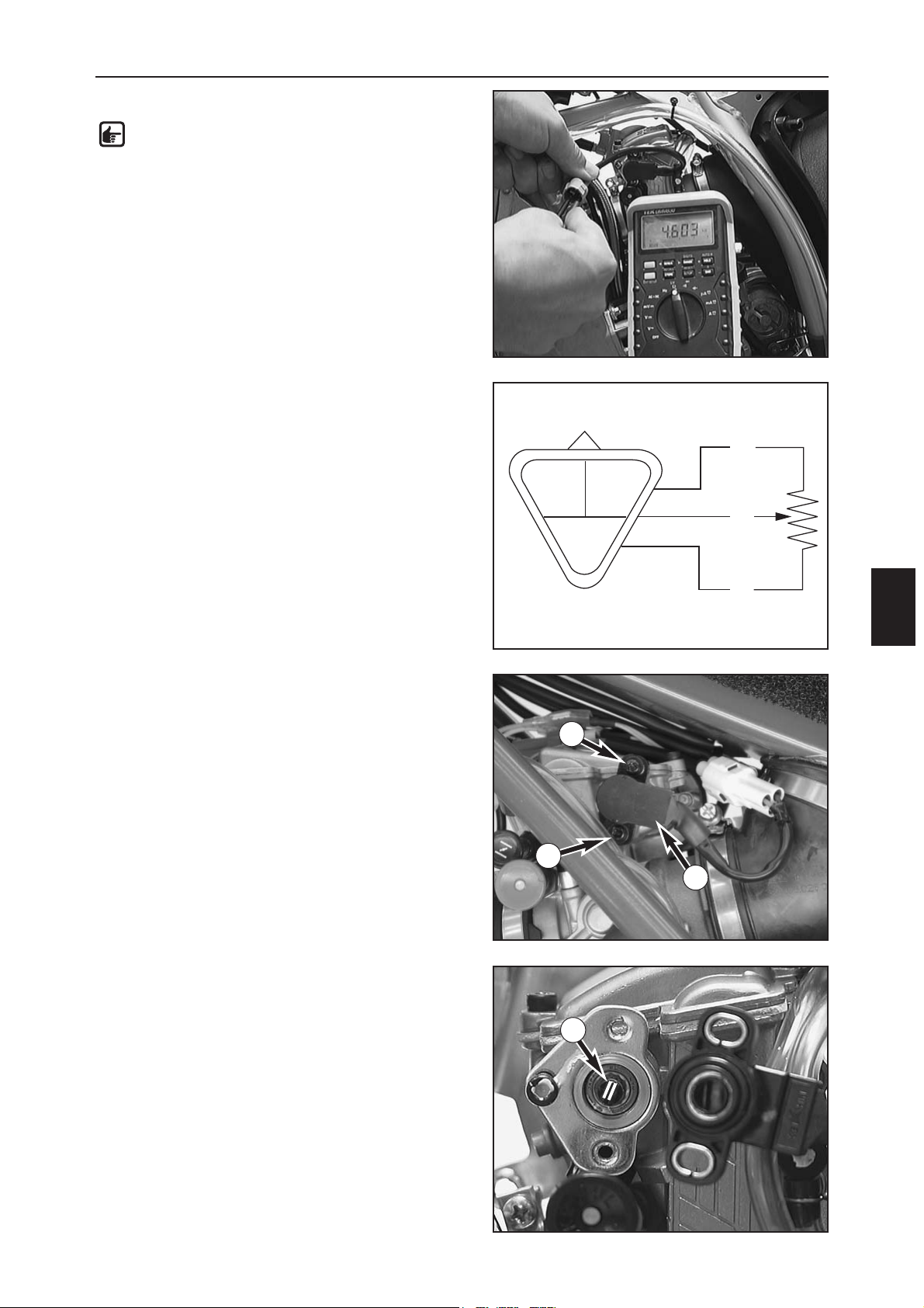
FUEL SYSTEM
G
11
CHECKING THE THROTTLE SENSOR
NOTE: The following measurement must be
performed at a component temperature of
approx. 20°C.
–Disconnect the plug connection on the throttle sensor.
– Connect a multimeter (measuring range . x 1k) to the
blue (+) and the black (–) cable on the throttle sensor.
Throttle sensor resistance: 4 - 6 kΩ
– Now connect the multimeter to the yellow (+) and the
black (–) cables on the throttle sensor.
– The resistance should change evenly when the throttle
grip is slowly opened.
Throttle sensor resistance: 0 - 5 kΩ ±1 kΩ
(when the throttle grip is opened)
DISMOUNTING AND MOUNTING THE
THROTTLE SENSOR
–Disconnect the plug connection on the throttle sensor
lösen and remove the screws (1).
– Remove the throttle sensor (2) from the carburetor.
– When you mount the throttle sensor, make sure that
the flat area on the driver (3) engages in the groove in
the throttle sensor.
– Degrease the thread on the 2 screws and apply
Loctite 243.
– Mount the 2 screws but do tighten yet and adjust the
position of the throttle sensor.
bu
bu
ye
ye
bl
bl
bu = blue
ye = yellow
bl = black
1
1
2
3
Page 93
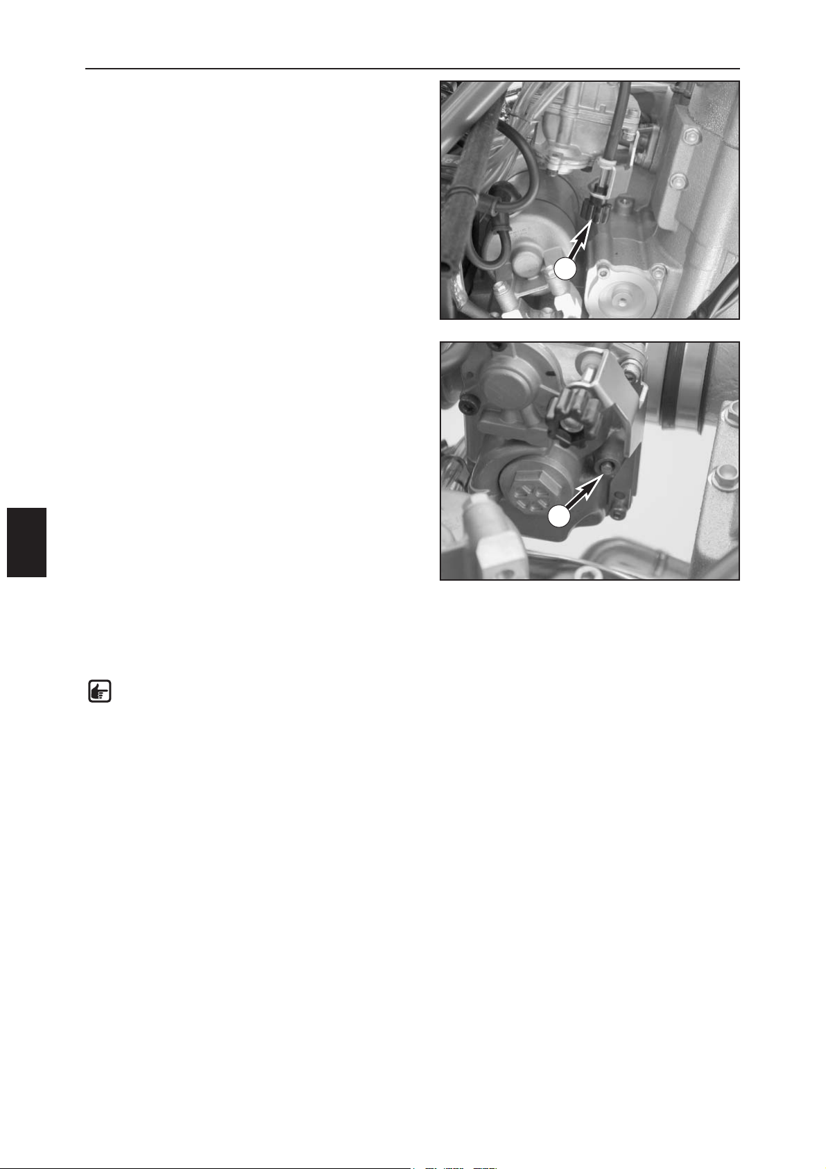
FUEL SYSTEM
G
12
ADJUSTING THE CARBURETOR IDLE
The carburetor idle setting has a strong influence on the
engine's starting behavior. In other words, an engine with
a correctly adjusted idle will be easier to start than an
engine with an incorrectly adjusted idle.
The idle is adjusted via the adjusting knurl (1) and the
mixture control screw (2). The basic throttle slide position
is adjusted with the adjusting knurl. The mixture control
screw is used to adjust the idle mixture which flows
through the idle system to the engine. Turning in a
clockwise direction will reduce the amount of fuel (lean
mixture), turning in a counterclockwise direction will
increase the amount of fuel (rich mixture).
To adjust the idle, proceed as follows:
1Turn the mixture control screw (2) in all the way to the
stop and adjust to the basic setting specified by
Husaberg (see Technical Specifications - Engine).
2 Run the engine warm
3Use the adjusting knurl (1) to set a normal idle speed
(1400 - 1500/min).
4Slowly turn the mixture control screw (2) in a clockwise
direction until the idle speed starts to drop.
Note down the position and slowly turn the mixture
control screw in a counterclockwise direction until the
idle speed drops again. Set the point between these
two positions that has the highest idle speed. If the
speed increase is too high, reduce the idle speed to a
normal level and repeat as described in section 4.
Racing pilots will make the ideal setting approx. 1/4
turn leaner (in a clockwise direction), since the engine
becomes hotter while racing.
NOTE: if the mode of procedure described
above does not achieve satisfactory results, this
may be due to the wrong dimensioning of the
idling jet. If
a) the mixture control screw is turned in up to the stop
without any change in the speed, mount a smaller
idling jet.
b) the engine stalls with the mixture control screw 2
turns open, select a larger idling jet.
Repeat the adjustment procedure after replacing the
jet.
5 Now set the desired idle speed with the adjusting
knurl.
6 Readjust the idle for greater changes in the outdoor
temperature or extremely varying altitudes.
1
2
Page 94
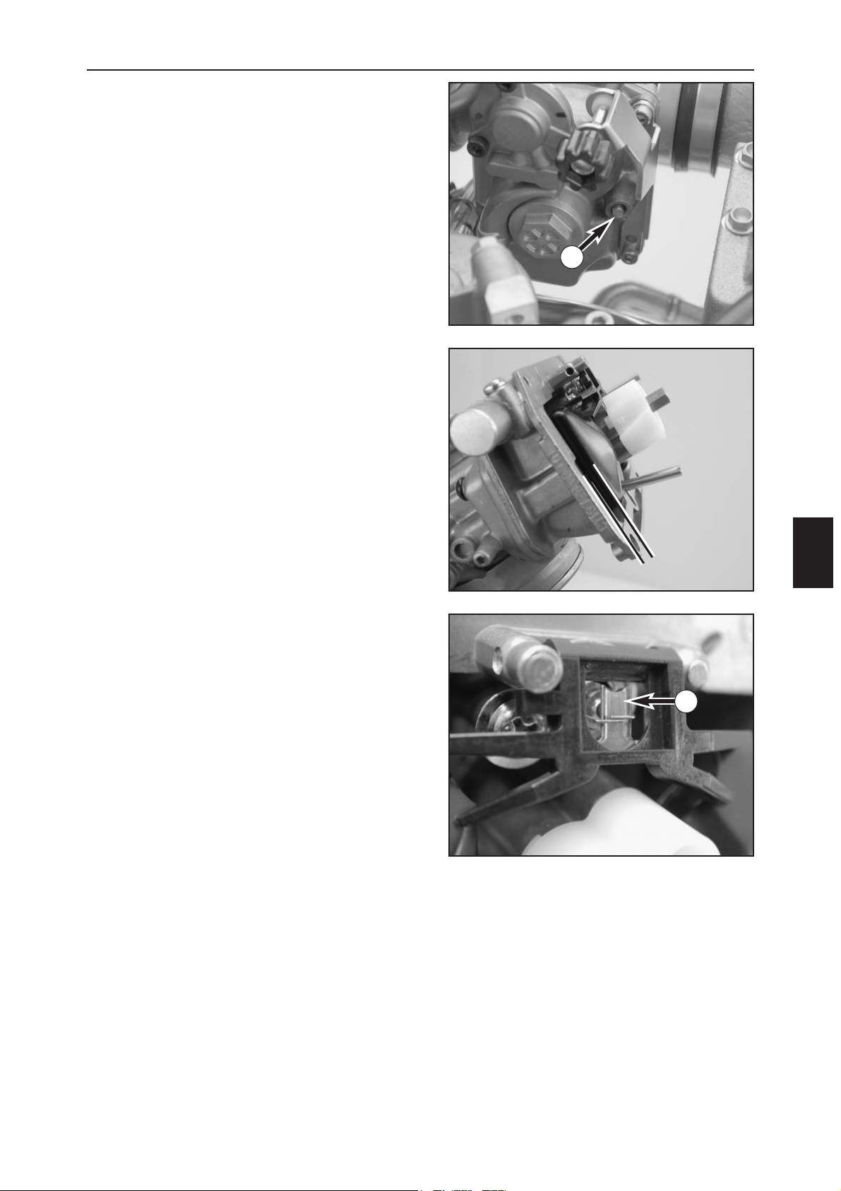
FUEL SYSTEM
G
13
GENERAL INFORMATION ON CARBURETOR
WEAR
Engine vibrations make the throttle slide, jet needle and
main jet holder subject to increased wear. Wear leads to
malfunctioning of the carburetor (e.g. over enrichment).
These parts should be replaced after 200 operating
hours.
ADJUSTING THE MIXTURE CONTROL SCREW
The mixture control screw (1) is used to adjust the idle
mixture.
Turning the mixture control screw in a clockwise direction
will reduce the idle mixture, turning it in a counterclockwise direction will increase the idle mixture.
CHECKING THE FLOAT LEVEL (FLOAT HEIGHT)
To check the float level, dismount the carburetor and
remove the float chamber. Tilt the carburetor until the
float rests against the float needle valve without crushing
it.
The edge of the float should be parallel to the sealing
area of the float chamber in this position (see photo).
If the float level does not have the setpoint value, check
the float needle valve and replace if necessary.
If the float needle valve is OK you can adjust the float
height by bending the float lever (2).
Mount the float chamber and the carburetor and adjust
the idle.
2
1
Page 95

Page 96

TROUBLESHOOTING
H
1
ERROR
Engine does not switch on
(starter)
Engine switches on but
does not start (starter)
Engine does not start
(kickstarter)
Engine has no idle
CAUSE
Operating error
Fuse is blown
Battery is dead
Low outdoor temperature
Operating error
Motorcycle was not operated
for a longer period of time,
old fuel in the float chamber
Fuel supply is interrupted
Engine is flooded
Spark plug is sooted or wet
Electrode distance is too large
Spark plug connector or spark
plug is defective
Short-circuit cable in the wiring
harness chafed, Emergency
OFF switch or short circuit
button is defective
Socket connector on CDI,
pulse generator or ignition coil
has oxydized
Water in the carburetor or jets
clogged
Idling jet clogged
Adjusting screws on the
carburetor are distorted
Spark plug is defective
Ignition system is defective
REMEDY
Switch on the emergency OFF switch (Australia only)
Replace the fuse in the starter relay
Charge the battery and determine the cause of
discharging
Start the engine with the kickstarter
Open the fuel tap, refuel, do not actuate the choke,
follow start-up instructions (see driving instructions)
The highly inflammable constituents in the new fuel
volatize if left standing over longer periods of time.
If the motorcycle was not used for over 1 week, drain
the old fuel from the float chamber. The engine will
start immediately after the float chamber is filled with
fresh ignitable fuel.
Disconnect the fuel hose from the carburetor, place
the end in a vessel and open the fuel tap,
– if fuel leaks out, clean the carburetor
– if no fuel leaks out, check the tank ventilation and
clean the fuel tap
To "pump“ the engine dry, pull the hand
decompression lever, open the throttle completely,
actuate the kickstarter 5 – 10 times or the starter 2
times for 5 seconds. Then start the engine as
described above.
If the engine still won't start, unscrew the spark plug
and dry.
Clean and dry or replace the spark plug
Set the electrode distance to 0.6 mm
Remove the spark plug, connect the ignition wire,
hold the spark plug against the ground (bright side
facing the engine) and start. A strong spark should be
visible at the spark plug.
– if there is no spark, replace the spark plug
– if there is still no spark, disconnect the spark plug
connector from the ignition wire, hold approx. 5 mm
away from the ground and start
– if there is a spark, replace the spark plug connector
– if there is still no spark, have the ignition system
checked
Remove the fuel tank, disconnect the cable from the
emergency OFF switch or short-circuit button and
check the spark.
If there is a spark, look for the error in the short circuit
Remove the seat, clean the socket connector and
treat with contact spray
Dismount and clean the carburetor
Disassemble the carburetor and clean the jets
Adjust the carburetor
Replace the spark plug
Check the ignition system
Page 97

TROUBLESHOOTING
H
2
ERROR
Engine won't rev up
Engine does not have
enough power
Engine stops or backfires in
the carburetor
Engine gets too hot
High oil consumption
All of the switched on lights
are burned out
Horn, turn signal and
starter do not work
Battery is dead
CAUSE
Carburetor overflows because
the float needle is soiled or
worn
Loose carburetor jets
Electronic ignition advance is
defective
Fuel supply is interrupted or
the carburetor soiled
Air filter is heavily soiled
Exhaust system is not tight,
deformed or there is not
enough glass-fiber yarn in the
silencer
Valve clearance is too small
Compression loss due since
hand decompression lever is
inadequately adjusted
Electronic ignition advance is
defective
Shortage of fuel
Engine drawns in unmetered air
Not enough cooling liquid in
the cooling system
Not enough air stream
Cooling system not ventilated
Radiator fins are heavily soiled
Foam has formed in the
cooling system
Bent radiator hose
Bent engine ventilation hose
Engine oil level is too high
Engine oil is too thin
The voltage regulator is
defective
Fuse in the starter relay is
blown
Battery is not being charged
by the generator
REMEDY
Disassemble the carburetor and check for wear
Tighten the jets
Check the ignition system
Clean and check the fuel system and carburetor
Clean or replace the air filter
Check the exhaust system for damage, replace the
glass fiber yarn in the main silencer
Adjust the valve clearance
Adjust the hand decompression cable
Check the ignition system
Clean and check the fuel system and carburetor
Check the rubber sleeve and carburetor for a tight fit
Add cooling liquid (see maintenance work), check
the cooling system for tightness
Continue driving speedily
Ventilate the cooling system
Clean the radiator fins with a water jet
Replace the cooling liquid, use brand-name
antifreeze
Shorten or replace the radiator hose
Install the ventilation hose without kinks or replace
Check the engine oil level and correct if necessary
Use a thicker engine oil, see "Engine oil“ chapter
(viscosity)
Check the voltage regulator
Renew the fuse
Check the connections on the voltage regulator
Page 98
TECHNICAL SPECIFICATIONS - ENGINE
I
1
Engine FC 450/4 FE 450e/6 FS 450e/6 FE 501e/6
Design Liquid-cooled, 1-cylinder 4-stroke Otto engine with balancer weight
Displacement 449 cm
3
501 cm
3
Bore/Stroke 100 / 57,2 mm 95 / 70,7 mm
Compression ratio 13:1 11,6:1
Keihin carburetor FCR-MX 41 FCR-MX 39
Fuel unleaded fuel with at least RON 95 (USA = Premium RON 91)
Timing 4 valves controlled over rocker arm and 1 camshaft, camshaft drive with single chain
Valve diameter, intake 35 mm
Valve diameter, exhaust 30 mm
Valve clearance, intake, cold
0,12 mm
Valve clearance, exhaust, cold
0,12 mm
Crankcase bearing 2 roller bearings
Conrod bearing needle bearing
Piston pin bearing bronze bush
Piston Light allow – forged
Piston rings 1 compression ring, 1 oil scraper ring
Engine lubrication pressure lubrication with trochoid rotor pump
Engine oil fully synthetic engine oil (Motorex Power Synt 4T SAE 10W50)
Quantity of engine oil 1.0 liter
Primary drive straight-toothed spur wheels 29:78 Z
Clutch multi-disk clutch in oil bath
Transmission (claw shifted) 4-speed 6-speed
Gear ratio
1st gear 14:33 14:33
2nd gear 17:30 17:30
3rd gear 19:26 19:26
4th gear 23:25 23:25
5th gear – 24:22
6th gear – 27:20
Ignition system
breakerless transitorized DC-CDI ignition system with digital ignition advance, type KOKUSAN
Generator – 12V 150W
Spark plug NGK DCPR 8 E
Electrode distance 0,6 mm
Cooling system liquid cooled, permanent circulation of cooling liquid through water pump
Cooling liquid 1.0 liters, mixing ratio 40% antifreeze, 60% water,at least –25° C
Starting aid kickstarter kickstarter/electric starter
BASIC CARBURETOR SETTING
Type of carburetor Keihin FCR-MX 41 Keihin FCR-MX 39 Keihin FCR-MX 39
Carburetor ID number 4125B 3925B 3925BA
Main jet 182 178 178
Jet needle OBDVR OBDVT (OBDVR) OBDVT (OBDVR)
Idling jet 40 38 (40) 38 (42)
Main air jet 200 200 200
Idle air jet 100 100 100
Needle position 6th from top 2nd (6th) from top 3rd from top
Starting jet 85 85 85
Mixture control screw open 1,5 1,5 (2,0) 1,5
Slide 15 15 15
Restriction – slide stop slide stop
Pump diaphragm stop 858 / 2,15 mm 858 / 2,15 mm 858 / 2,15 mm
Hot start knob diameter 2,5 mm diameter 2,5 mm diameter 2,5 mm
FC 450/4
FE/FS 450e/6
EU/AUS/USA green
FE 501e/6
EU/AUS
Page 99
TECHNICAL SPECIFICATIONS - ENGINE
I
2
Engine FC 550/4 FE 550e/6 FE 650e/6 FS 650e/6
Design Liquid-cooled, 1-cylinder 4-stroke Otto engine with balancer weight
Displacement 550 cm
3
644 cm
3
Bore/Stroke 100 / 70 mm 100 / 82 mm
Compression ratio 11,8:1 11,5:1
Keihin carburetor FCR-MX 41
Fuel unleaded fuel with at least RON 95 (USA = Premium RON 91)
Timing 4 valves controlled over rocker arm and 1 camshaft, camshaft drive with single chain
Valve diameter, intake 35 mm
Valve diameter, exhaust 30 mm
Valve clearance, intake, cold
0,12 mm
Valve clearance, exhaust, cold
0,12 mm
Crankcase bearing 2 roller bearings
Conrod bearing needle bearing
Piston pin bearing bronze bush
Piston Light allow – forged
Piston rings 1 compression ring, 1 oil scraper ring
Engine lubrication pressure lubrication with trochoid rotor pump
Engine oill fully synthetic engine oil (Motorex Power Synt 4T SAE 10W50)
Quantity of engine oil 1,0 liter
Primary drive straight-toothed spur wheels 29:78t
Clutch multi-disk clutch in oil bath
Transmission (claw shifted) 4-speed 6-speed
Gear ratio
1st gear 14:33 14:33
2nd gear 17:30 17:30
3rd gear 19:26 19:26
4th gear 23:25 23:25
5th gear – 24:22
6th gear – 27:20
Ignition system
breakerless transitorized DC-CDI ignition system with digital ignition advance, type KOKUSAN
Generator – 12V 150W
Spark plug NGK DCPR 8 E
Electrode distance 0,6 mm
Cooling system liquid cooled, permanent circulation of cooling liquid through water pump
Cooling liquid 1.0 liters, mixing ratio 40% antifreeze, 60% water,at least –25° C
Starting aid kickstarter kickstarter/electric starter
BASIC CARBURETOR SETTING
Type of carburetor Keihin FCR-MX 41 Keihin FCR-MX 41 Keihin FCR-MX 41
Carburetor ID number 4125B 4125B 4138C
Main jet 182 182 160
Jet needle OBDVR OBDVT (OBDVR) OBDVT (OBEKR)
Idling jet 40 38 (40) 38 (45)
Main air jet 200 200 200
Idle air jet 100 100 100
Needle position 5th from top 5th from top 2nd (6th) from top
Starting jet 85 85 85
Mixture control screw open 1,5 1,5 0,5 (1,5)
Slide 15 15 15
Restriction – slide stop slide stop
Pump diaphragm stop 858 / 2,15 mm 858 / 2,15 mm 858 / 2,15 mm
Hot start knob diameter 2,5 mm diameter 2,5 mm diameter 2,5 mm
FC 550/4 FE/FS 550e/6
EU/AUS/USA green
FE/FS 650e/6
EU/AUS/USA green
Page 100
TECHNICAL SPECIFICATIONS - CHASSIS
I
3
FC 450/4, 550/4 FE 450/501/550/650e/6
FS 450e/6, 650e/6
Frame tubular chrome-molybdenum-steel frame, powder-coated
Fork WP Up Side Down 4860 MXMA
Spring travel, front/rear 295/320 mm 260/287 mm
Rear suspension WP Progressive Damping System shock absorber, aluminum rear swinging fork
Front brake
Disk brake,perforated Ø 260 mm brake disk, floating brake caliper
Ø 310 mm
Brake disk front minimum thickness 2,5 mm minimum thickness 5,0 mm
Rear brake Disk brake,perforated Ø 220 mm brake disk, floating brake caliper
Brake disk rear minimum thickness 3,5 mm
Front tire 80/100 - 21“ 90/90 - 21“ 120/60 - 17“
Air pressure, off road 1,0 bar 1,0 bar –
Air pressure, on road/alone
– 1,5 bar 1,5 bar
Rear tire 110/100 - 19“ 140/80 - 18“ 150/60 - 17“
Air pressure, off road 1,0 bar 1,0 bar –
Air pressure, on road/alone
– 2,0 bar 2,0 bar
Fuel tank capacity 9 liters
Gear ratio - rear wheel 14:48
450/501 14:48,550 15:48,650 15:45
450 15:42, 650 15:40
Chain X-Ring 520
Available rear sprockets 38Z, 40Z, 42Z, 45Z, 48Z, 50Z, 52Z
Lighting Headlight HS1 12V 35/35W
Parking light 12V 5W (Socket W2, 1x9,5d)
Brake light 12V 21/5W (Sockel BaY15d)
Turn signal 12V 10W (Sockel Ba15s)
License plate illumination 12V 1,2W (Sockel 1x4,6d)
Battery maintenance-free battery 12V 7Ah
Steering head angle 63°
Wheel base 1490 ± 10 mm
Seat height, unloaded 930 mm 870 mm
Ground clearance, unloaded
380 mm 320 mm
FC 450/4, 550/4 FE 450/501/550/650e/6 FS 450e/6, 650e/6
WP 5018 PDS DCC WP 5018 PDS DCC WP 5018 PDS DCC
12.45.Y7.21 12.45.Y7.22 12.45.Y7.23
Compression damping 15 LS (low speed) 15 LS (low speed) 10 LS (low speed)
2 HS (high speed) 2 HS (high speed) 2 HS (high speed)
Rebound damping 22 22 15
Spring 76/95/260 71/90/260 84/250
Spring preload 6 mm 8 mm 5 mm
STANDARD SHOCK ABSORBER ADJUSTMENT
FC 450/4, 550/4 FE 450/501/550/650e/6 FS 450e/6, 650e/6
WP4860MXMA WP4860MXMA WP4860MXMA
14.45Y7.28 14.45Y7.29 14.45Y7.30
Compression damping 18 19 20
Rebound damping 19 21 15
Spring 4,4 N/mm 4,2 N/mm 4,4 N/mm
Spring preload 5 mm 5 mm 33 mm
Air chamber length 100 mm 110 mm 110 mm
Fork oil SAE 5 SAE 5 SAE 5
STANDARD FORK ADJUSTMENT
 Loading...