

Page 1
273055085 US
Unitool SC 250 M
(Original instruction manual)
replaced 11.2011
Instruction manual for rescue equipment
Edition 07.2014
Built to extend lives.™
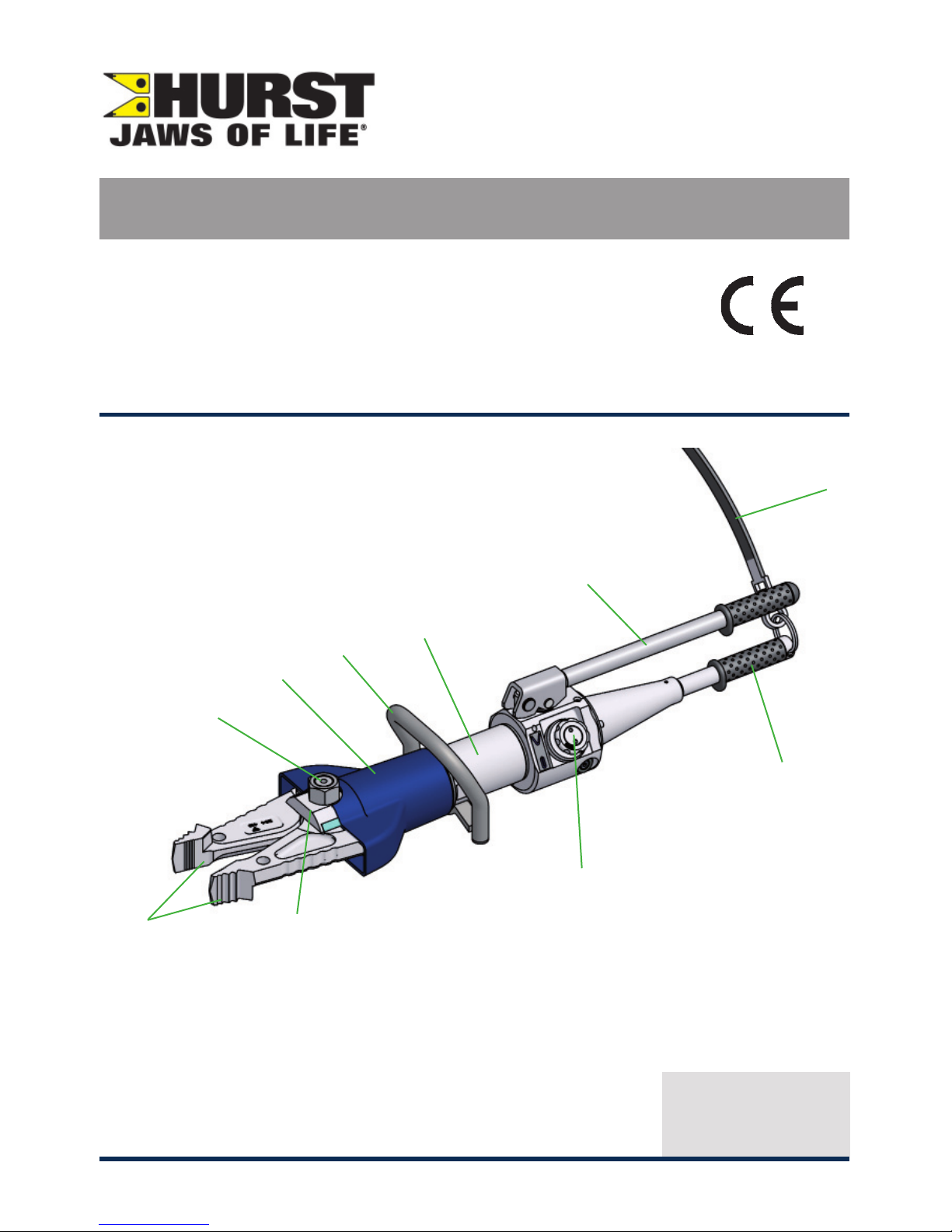
1 Rotary knob (control valve)
2 Hand lever
3 Equipment body
4 Handle
5 Protective hose
6 Blade arm
2
1
10
6
7
4
8
9
3
5
7 Pivot bolt with self-locking
nut
8 Rotatable tool head
9 Grab handle
10 Carrying strap
Page 2

2
Page 3

3
Content Page
1. Hazard classes 4
2. Product safety 5
3. Intended use 8
4. Description of function 9
4.1 Description 9
4.2 Operational control 9
5. Operation 10
5.1 Controlling the working direction 10
5.2 Blade arm movement 10
6. Cutting, spreading, pulling and squeezing 11
6.1 Safety information 11
6.2 Cutting 12
6.3 Spreading 13
6.4 Pulling 13
6.5 Squeezing 14
7. Dismantling the equipment / deactivation after use 14
8. Care and maintenance 14
9. Repairs 16
9.1 General 16
9.2 Preventative maintenance 16
9.3 Repairs 17
10. Troubleshooting 19
11. Technical data 20
11.1 Combi tools 20
11.2 Pivot bolt tightening torques 21
11.3 Cutting performance 21
11.4 Temperature ranges for operating and storage 21
12. EC declarations of conformity 22
13. Notes 23
Page 4
4
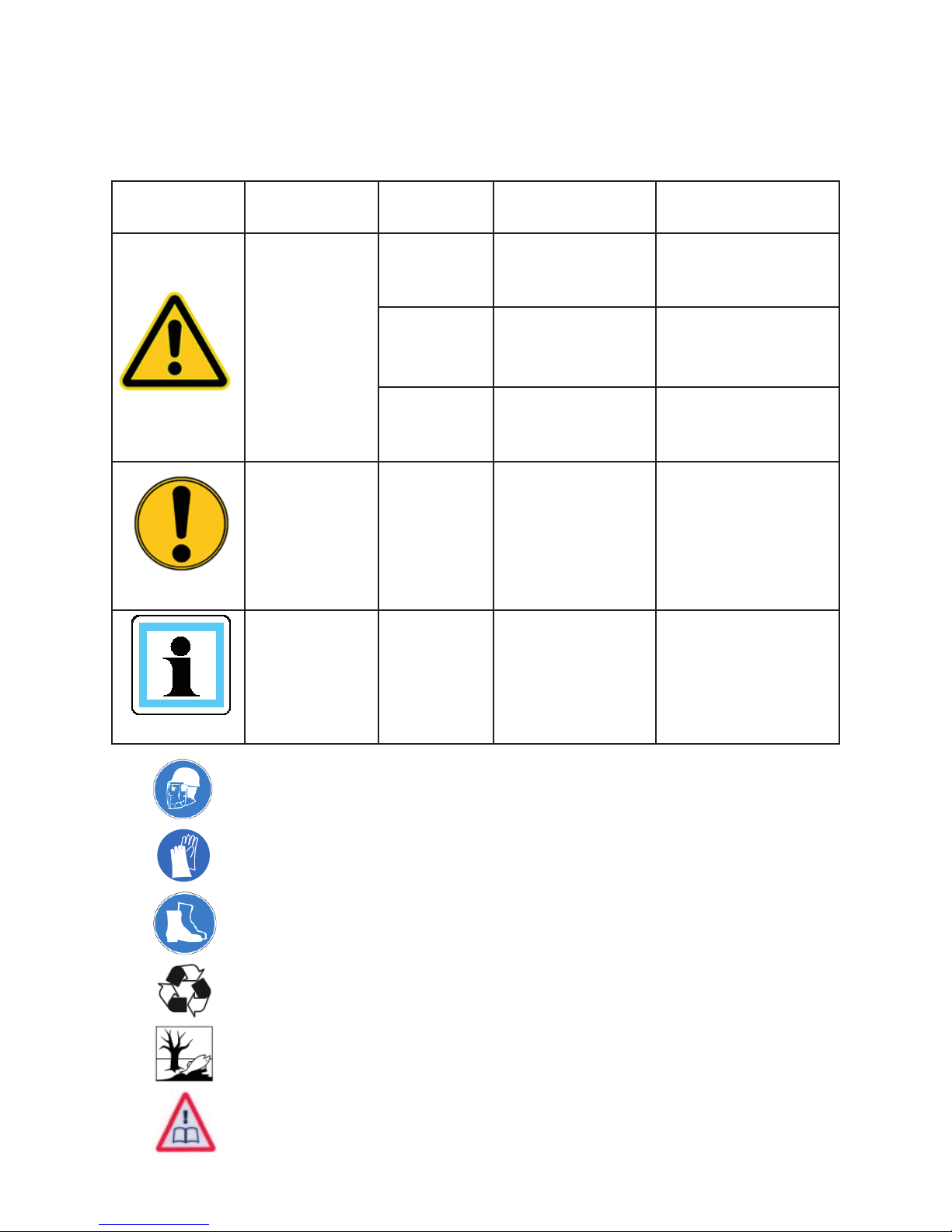
Wearing helmets with face protection
Wearing safety gloves
Wearing protective footwear
Respecting recycling requirements
Observing environmental protection regulations
Reading and following operating instructions
We distinguish between various categories of safety instructions. The table below gives you
an overview of the assignment of symbols (pictograms) and key words to the specifi c hazard
and possible consequences.
1. Hazard classes
Pictogram
Damage /
injury to
Key word Defi nition Consequences
human
DANGER! Immediate danger Death or major injury
WARNING!
Potentially
dangerous
situation
Potential death or
major injury
CAUTION!
Less dangerous
situation
Minor or slight injury
device
CAUTION!
Danger of damage
to device /
environment
Damage to the
equipment, damage
to the environment,
damage to
surrounding materials
- NOTE
Advice for
application and
other important /
useful information
and advice
No injury / damage
to persons /
environment /
equipment
Page 5
5
2. Product safety
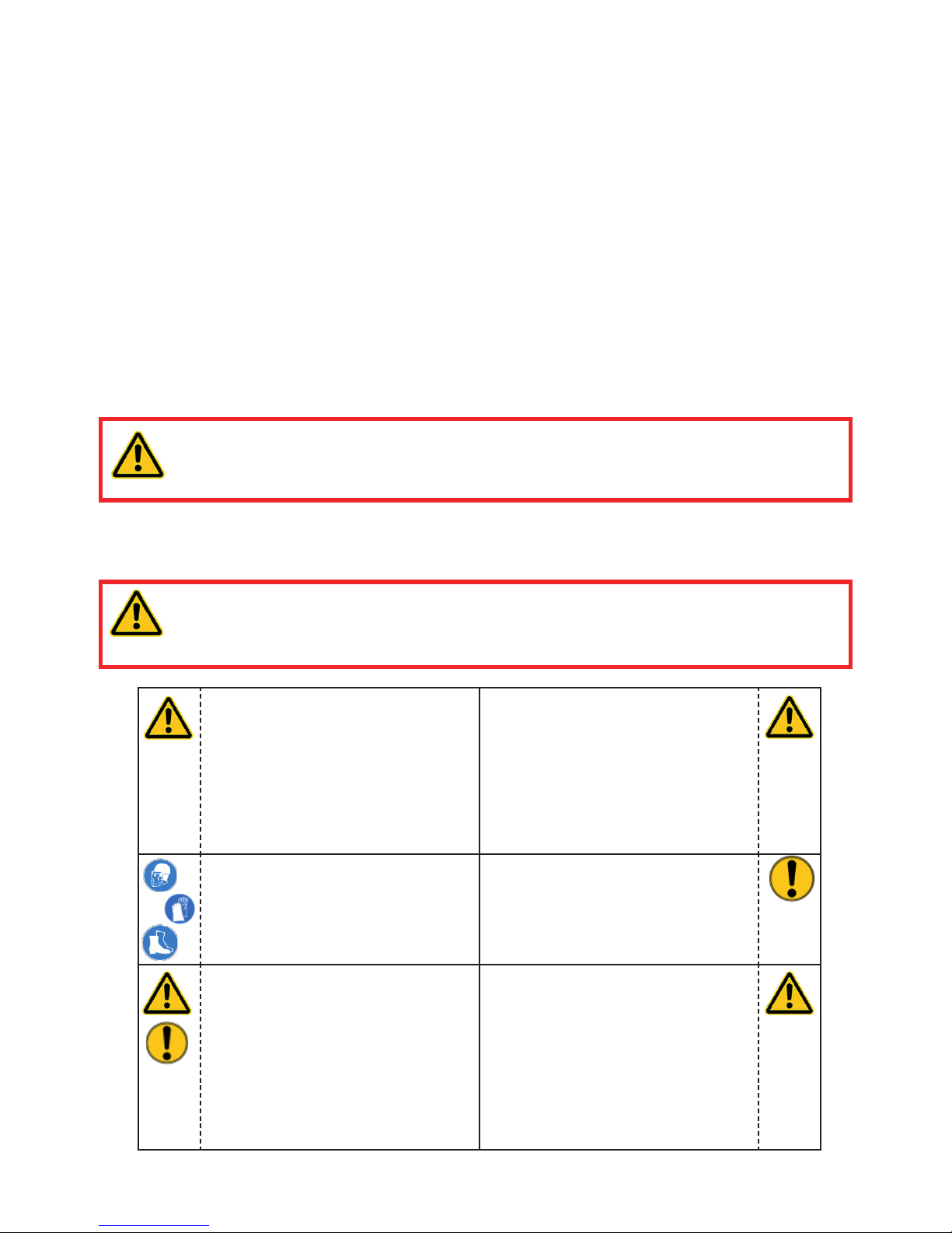
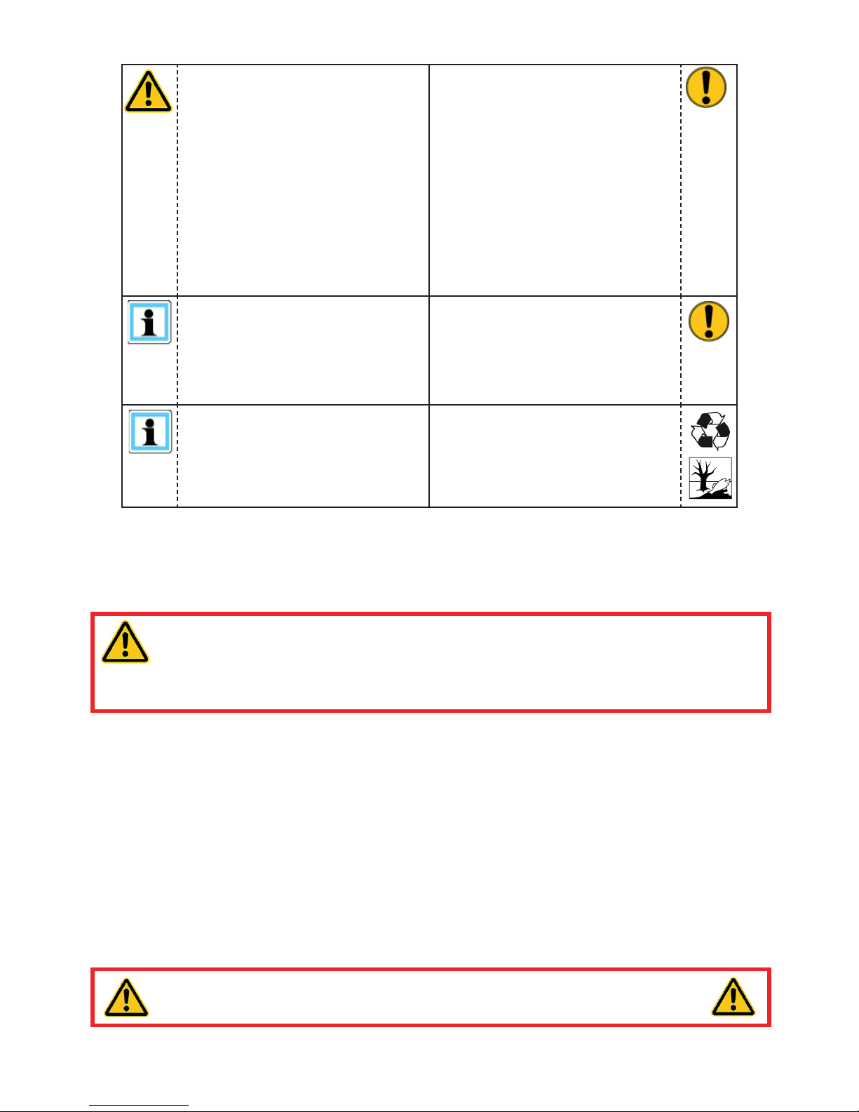
Please ensure that no body
parts or clothing get stuck
between the visibly moving
parts (e.g. blade arms).
It is prohibited to work under
load if this load is lifted
exclusively by hydraulic
equipment. If this work
is absolutely imperative,
additional mechanical
supports must be used.
Wear protective clothing,
safety helmet with visor,
protective gloves
Inspect the equipment before
and after use for visible
defects or damage
Immediately report any
changes that occur (including
changes in operating
behaviour) to the appropriate
persons/departments! If
necessary, the device is to be
deactivated immediately and
secured!
Check all screwed fi ttings
for leaks and externally
detectable damage and
rectify immediately! Squirting
hydraulic fl uid can result in
injuries and fi res.
HURST products are developed and manufactured in order to guarantee the best
performance and quality when used properly.
Operator safety is the most important aspect of the product design. Furthermore, the
operating instructions are intended to help in using HURST products safely.
The generally applicable, legal and other binding regulations pertaining to the prevention of
accidents and protection of the environment apply and are to be implemented in addition to
the operating instructions.
The device may only be operated by persons with appropriate training in the safety aspects
of such equipment – otherwise, there is a danger of injury occurring.
We would like to point out to all users that they should read carefully the operating instructions
and the instructions contained therein before they use the device, and that they should
carefully follow such.
We also recommend that you get instructed by a qualifi ed trainer in the use of the product.
WARNING / CAUTION!
The operating instructions for the hoses, the accessories and the connected
hydraulic equipment must also be observed!
Even if you have already received instructions on how to use the equipment, you should still
read the following safety notes through again.
WARNING / CAUTION!
Ensure that the Technical Data of any accessories used comply with the
maximum power rating of the equipment!
Page 6
6
In the event of malfunctions,
immediately deactivate the
equipment and secure it. The
malfunction is to be repaired
immediately.
Do not carry out any changes
(additions or conversions) to
the device without obtaining
the prior approval of HURST
Observe all safety and danger
notes on the device and in the
operating instructions.
All safety and danger notes
on the device are to be
kept complete in a legible
condition.
Any mode of operation which
impairs safety and/or stability
of the device is forbidden!
Comply with all specifi ed
dates or dates specifi ed in
the operating instructions
pertaining to regular controls /
inspections on the equipment.
Safety devices may never be
deactivated!
The maximum permitted
operating pressure noted on
the equipment must not be
exceeded.
Before the device is switched
on/started up, and during its
operation, it must be ensured
that nobody is endangered by
the operation of the device.
Only original HURST
accessories and spare parts
may be used for repairs.
When working close to live
components and cables,
suitable measures must
be taken to avoid current
transfers or high-voltage
transfers to the equipment.
Please note, when cutting or
spreading: cutting, tearing
or breaking can cause
material falling down or being
catapulted away because of
sudden removal. Necessary
precautions need to be taken!
The build-up of static
charge with the potential
consequence of spark
formation is to be avoided
when handling the device.
Only touch any broken-off
parts or the cut-off parts
wearing protective gloves,
since the torn / cut edges can
be very sharp.
Page 7
7
In addition to the safety information accompanying these operating instructions, all generally
applicable, legal and other mandatory national and international regulations pertaining to the
prevention of accidents and protection of the environment apply and must be complied with!
The device is fi lled with
a hydraulic fl uid. These
hydraulic fl uids can be
dangerous to health if
swallowed or their vapours
inhaled. Direct contact with
the skin is to be avoided for
the same reason. Please also
note that hydraulic liquids can
also have a negative effect on
biological systems.
When working with or storing
the device, ensure that the
function and the safety of the
device are not impaired by
the effects of stark external
temperatures or that the
device is damaged in any
way. Please note that the
device can also heat up over
a long period of use.
Ensure adequate lighting
when you are working.
Before transporting the
device, always ensure
that the accessories are
positioned such that they
cannot cause an accident.
Always keep these operating
instructions within reach
where the device is used.
Ensure the proper disposal of
all removed parts, left-over oil
and hydraulic fl uid as well as
packaging materials!
WARNING / CAUTION!
Sparking can occur when the equipment is used on metallic materials or when
metallic parts come into contact with hard or uneven surfaces!
Assess the nature of the working environment before operating the equipment!
WARNING / ATTENTION / CAUTION!
The equipment is to be used exclusively for the purpose stated in the operating
instructions (see Chapter entitled ‘Intended Use’) . Use of the equipment for any
purpose other than that stated or for any duty beyond its rated capacity shall be regarded as
imintended use. The manufacturer / supplier is not liable for any damages resulting from
imintended use. The risk shall be borne solely by the user.
Observance of the operating instructions and compliance with the inspection and maintenance
conditions are part of the intended use.
Never work in a fatigued or intoxicated state!
Page 8
8
3. Intended use
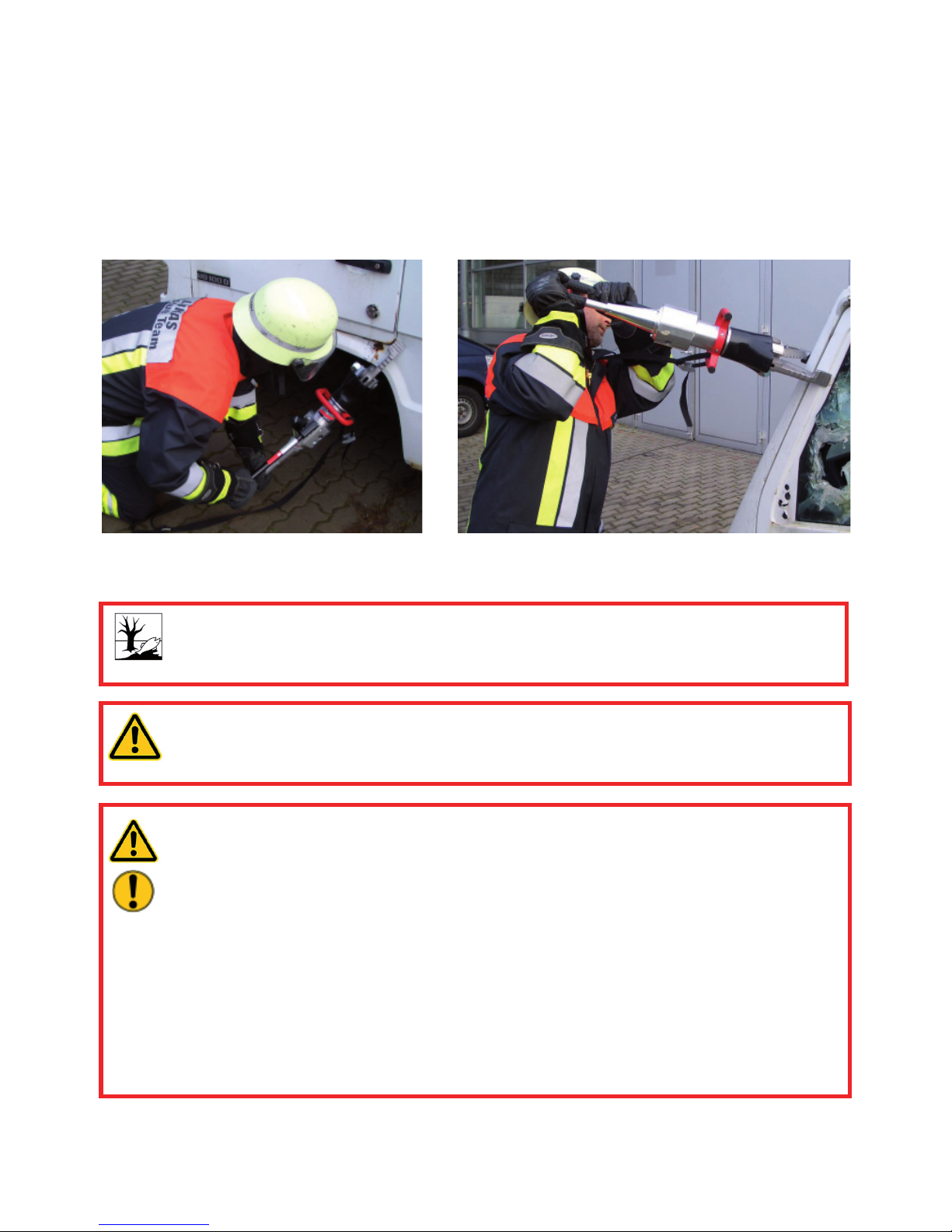
HURST handheld combi tools are specially designed for the rescue of casualties in road
accidents, rail accidents and in air travel, and for rescue from buildings. They serve the
purpose of freeing injured people in accidents e. g. by cutting doors, roof bars and hinges.
Trapped persons can also be freed using them e. g. by forcing open doors and/or by removing
obstacles with the aid of a chain set. HURST handheld combi tools can basically be used to
cut, pull, open, squeeze and lift objects.
You can obtain accessories and spare parts for the rescue device from your authorised
HURST dealer!
HURST handheld combi tools are also suitable for use underwater to depths of 40 m (131
ft) .
CAUTION!
In this case, you must strictly observe any leaks in order to avoid threats to the
environment.
WARNING / CAUTION!
All objects which are to be worked on are to be secured using stable supports or
substructures.
WARNING / ATTENTION / CAUTION!
The following may not be cut / squeezed:
- live electric cables
- pre-tensioned or hardened components, such as springs, spring steels,
steering columns and rollers
- pressurised piping containing gases or liquids,
- composite materials (steel/concrete)
- explosive objects, such as airbag cartridges
NEVER operate the rescue equipment at a higher operating pressure than that
stated in the chapter entitled ‘Technical Data’. A higher setting can result in
material damage and/or injuries.
Page 9
9
4. Description of function
4.1 Description
The HURST handheld combi tools are a combi tool and handpump rolled into one unit.
Hydraulic power packs and energy supply or accumulators are therefore not required to
generate the required hydraulic pressure.
This is generated by moving the attached handle, in exactly the same manner as a hand
pump.
The working section of the tool is confi gured so that two equal opposing blade arms with
mechanical joints open or close symmetrically in order to open, squeeze, pull or cut objects.
In addition, HURST handheld combi tools are fi tted with a tool head that can rotate through
360° to allow optimum application of the blade arms at all times and ensure optimum
pumping.
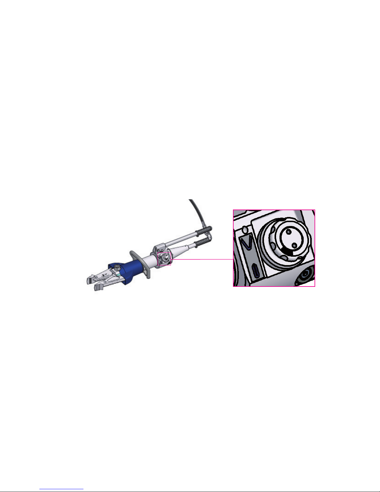
The working direction is adjusted before actuating the hand lever by turning the rotary knob
to the desired switching end point (see Cover Sheet Item 1).
4.2 Operational control
The hand lever is actuated to move the two blade arms in the specifi ed working direction.
Page 10
10
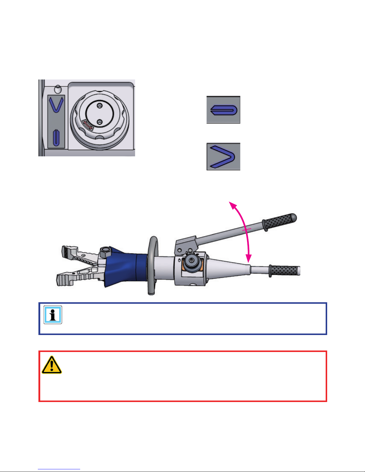
Counterclockwise = closing blade arms - Cutting
Clockwise = opening blade arms - Spreading
5.1 Controlling the working direction
5. Operation
5.2 Blade arm movement
The working direction is adjusted before actuating the hand lever by turning the rotary knob
to the desired switching end point.
Actuate the hand lever (up and down movement) to move the two blade arms in the set
working direction.
NOTE:
We recommend using full strokes when pumping. This means moving the hand
lever the full distance from one end stop to the other.
WARNING / CAUTION!
The hand lever can spring back when operating. This can be caused by excess
hydraulic pressure within the equipment or by external loading.
When operating the equipment, therefore, position yourself in such a way that you
will not be injured if the lever springs back.
Page 11
11
6. Cutting, spreading, pulling and squeezing
6.1 Safety information
Before rescue works can commence, the position of the obstacle must be stabilised.
You must ensure an adequate substructure and / or adequate support of the object.
World-wide, safety guidelines pertaining to the specifi c country are to be observed and
complied with. In the Federal Republic of Germany, safety testing is carried out on a regular
basis, in accordance with GUV (German Legal Accident Insurance) regulations.
The following are to be worn when working with the rescue equipment:
- protective clothing,
- helmet with visor or goggles,
- safety gloves
- and ear defenders
Before activating the rescue equipment, always ensure that there is no danger to persons
either involved / uninvolved in the action by the movement of the rescue equipment or by
fl ying fragments. Further avoid unnecessary damage to property belonging to others, objects
not involved by the rescue equipment / fl ying fragments.
Reaching between the blade arms is strictly forbidden!
WARNING / CAUTION!
The particular effect of the force of the rescue equipment during operation could
cause pieces of the vehicle to break off or fl y off, posing a danger to persons.
Ensure that any persons not participating in the rescue are kept at an appropriate
distance from the equipment.
Page 12
12
6.2 Cutting
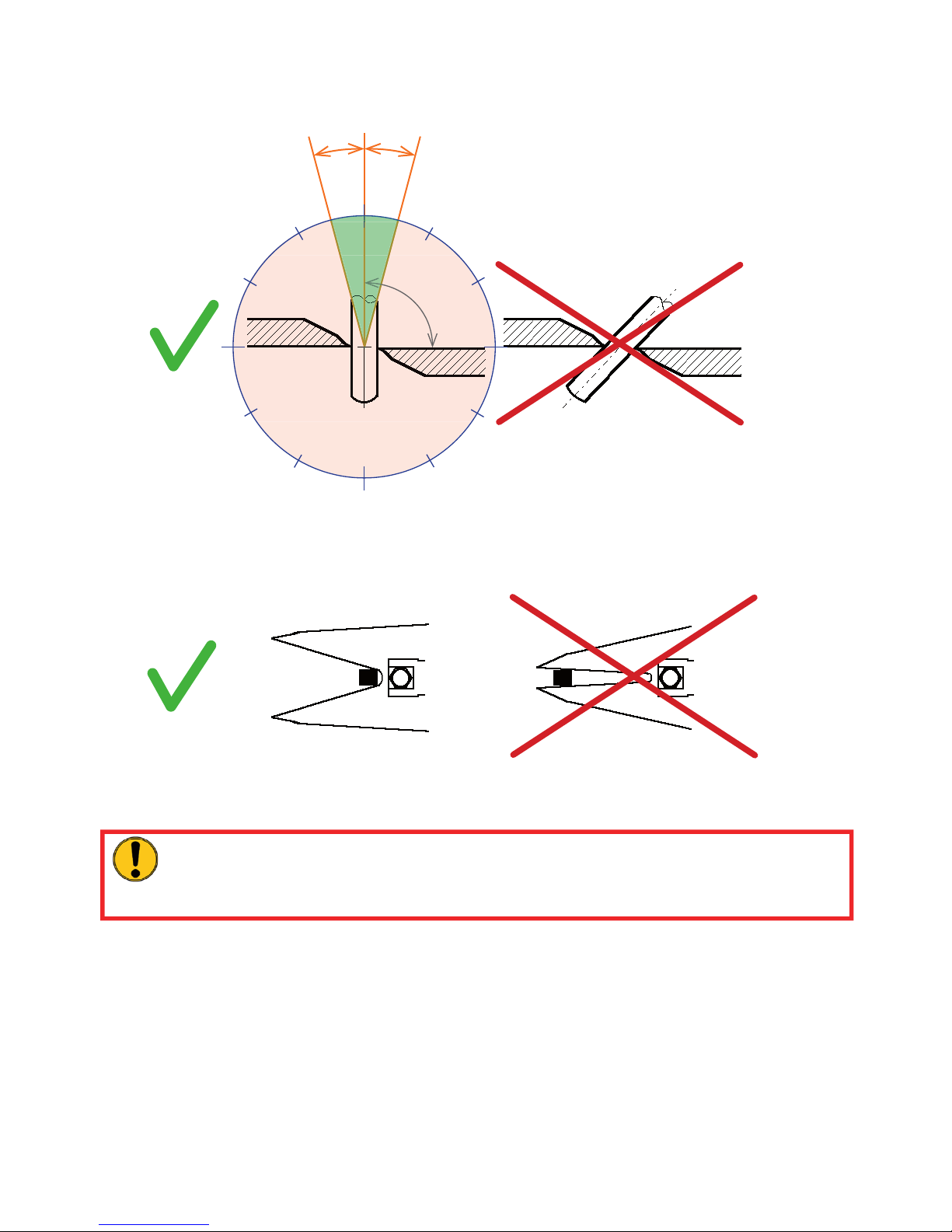
The blades must be positioned at a 90° angle to the object to be cut.
Higher cutting capacities can be achieved by cutting as close as possible to the blade’s pivot
point.
During cutting, the gap between the blade tips (in the transverse direction) must not be
exceed of 3 mm (0.12 in.), otherwise the blade is in danger of breaking.
CAUTION!
Avoid cutting particularly high-strength parts of the vehicle’s bodywork (e.g.
side-impact protection): this almost always damages the combi tool!
RIGHT
RIGHT
WRONG
WRONG
12
6
9
3
15°
15°
90°
Page 13
13
6.3 Spreading
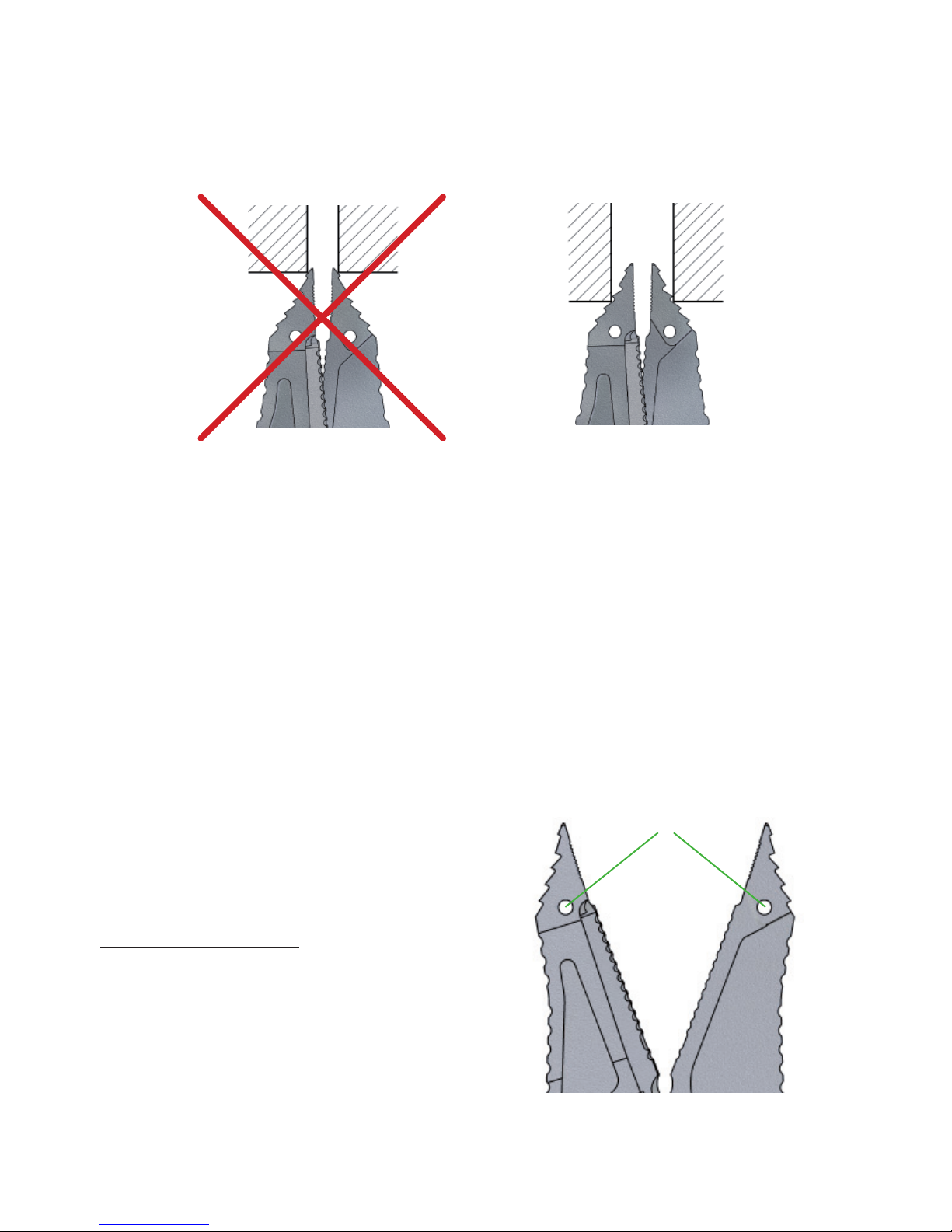
Use the front area of the tips for increasing the gap only. Full spreading capacity can be
achieved when approximately half of the grooved area of the tips is used. The greatest force
is created in the rear area of the spreading range of the combi blade.
Working surface is too small,
tips slip off.
Only for increasing the size
of a gap (not suitable for
spreading)
Tips get a safe grip.
6.4 Pulling
You may only use HURST chain sets for pulling purposes.
Before the pulling process can be performed, ensure that the bolt and hook fi t correctly to
prevent the chain from slipping.
Only chain sets in perfect condition may be used!
The pull chains are to be inspected at least once per year by an expert!
See separate operating instructions for the relevant HURST chain set in order to
correctly attach, affi x and use the chain sets.
Use load bolts to fasten the HURST
chainset connecting pieces to the blades
(drilled holes ‘A’). (see diagram right)
recommended chainset: KSV 8/50
A
Page 14
14
6.5 Squeezing
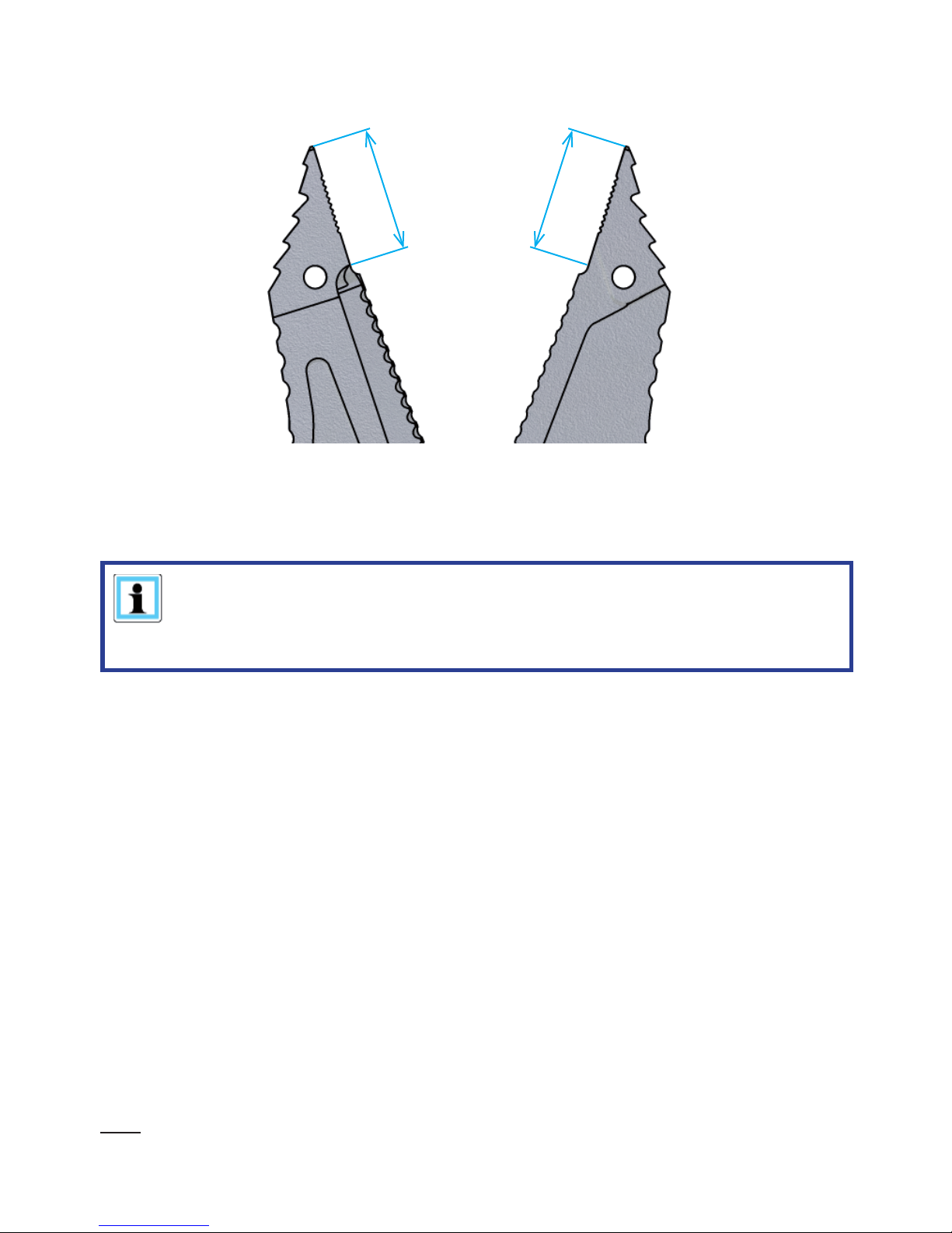
Basically, squeezing may only be carried out in the area of the tips (see fi gure below).
Squeezing area
7. Dismantling the equipment / deactivation after use
Once work has been completed, the blade arms are to be closed so that there is a tip
distance of just a few mm. This relieves the hydraulic and mechanical strain on the device.
Free the rescue equipment of any stubborn dirt which may have become attached during
use.
If the equipment is to be stored for a longer period of time, the exterior is to be cleaned
completely and the mechanically mobile parts are to be lubricated.
Avoid storing the rescue equipment in a damp environment.
NOTE:
Never store the combi tool with the blade arms fully closed! The complete
closure of the blade arms can cause hydraulic and mechanical stress to build
up again.
8. Care and maintenance
The equipment are subject to very high mechanical stresses. A visual inspection is to be
carried out after every use: however, at least one visual inspection is to be carried out every
six months. These inspections enable the early detection of wear and tear, which means
that punctual replacement of this wearing parts prevents breakages from occurring. Also
regularly check the torque of the pivot bolt. (For tightening torques M
A
see ‘Technical Data’)
Fracture testing of the blades must be carried out after 3 years. Therefore a special crack
testing kit is available.
Every three years or if there is any doubt regarding the safety or reliability of the equipment,
a function test must also be performed. (Please also observe the relevant valid national and
international regulations pertaining to service intervals of rescue equipment). In the Federal
Republic of Germany, safety testing is carried out on a regular basis, in accordance with
GUV (German Legal Accident Insurance) regulations.
Page 15

15
CAUTION!
Clean off any dirt before checking the device!
When cleaning the equipment, ensure that no cleaning agents are used with pH
values outside the range 5 - 8!
WARNING / ATTENTION / CAUTION!
In order to carry out maintenance and repair works, tools appropriate for the job
and personal protecting equipment are essential.
Inspections to be carried out:
Visual inspection
• Opening width of the blade arms at the tips (see chapter ‘Technical Data’),
• General tightness (leaks),
• Ease of movement of the hand lever,
• Ease of movement of the rotary knob,
• Handle present and secure,
• Ease of rotational movement of tool head through 360°,
• Labeling complete and legible,
• Covers in undamaged condition,
• Check the pivot bolt tightening torque (tightening torque M
A
see ‘Technical Data’),
• Blade arms free of cracks and nicks or deformations on the cutting surfaces,
• Shearing surfaces pass over each other without making contact,
• Pins and circlips on the blade arms are present and in a proper condition,
• Grooving at the blade tips to be clean and square-edged with no evidence of cracking
(applies to combi tools)
Function test
• problem-free opening and closing when operating the hand lever and adjusting the rotary
knob,
• no suspicious noises.
• blade arms stop moving when the movement of the pump is interrupted during the process
(dead man’s handle)
Page 16
16
9.1 General
9. Repairs
Servicing may only be carried out by the manufacturer or personnel trained by the
manufacturer and by authorised HURST dealers.
When replacing components, only original HURST spare parts must be used (as detailed
in the Spare Parts List) and instructions relating to the use of special tools, assembly
procedures, safety aspects and testing must be complied with (see also the chapter entitled
‘Maintenance and Servicing’).
During assembly, ensure the complete cleanliness of all components, because dirt
can damage the rescue equipment!
WARNING / ATTENTION / CAUTION!
Protective clothes must be worn when repairs are being carried out, because
the equipment can also be pressurised in an idle state.
NOTE:
Register your equipment on the HURST Hydraulik GmbH Internet website. The
extended warranty will only be provided for equipment which has already been
registered.
CAUTION!
Because HURST rescue equipment is designed for the highest level of
performance, components may only be replaced with those specifi ed in the
spare parts list for the appropriate equipment.
Other components may be replaced only when:
- you have attended the relevant HURST training course.
- you have received explicit permission from the HURST Customer Service
Department. (After inquiry, examination for the distribution of permission.
Examination in each individual case necessary!)
9.2 Preventative maintenance
9.2.1 Care of the equipment
The equipment casing should be kept clean and oil should be regularly applied to the external
metal services to protect them from corrosion.
9.2.2 Function and load testing
Function and load testing should be carried out in the event of there being any doubt as to
the safety or reliability of the equipment.
HURST offers appropriate test equipment to this end.
CAUTION!
When cleaning the equipment, ensure that no cleaning agents are used with pH
values outside the range 5 - 8!
Page 17
17
9.3 Repairs
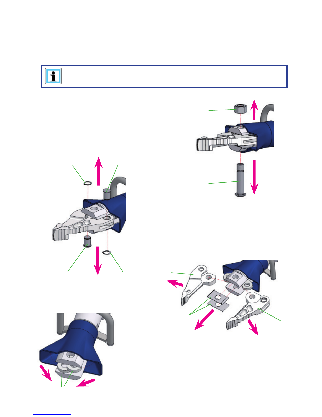
9.3.1 Replacing the blades, protection hose and handle
1. Start by carefully cleaning the rescue equipment.
2. Next, close the blade arms so that the tips are almost touching.
NOTE:
The blade bolts are only accessible when the blade arms are almost touching
3. Remove the self-locking nut ‘A’ and push the
pivot bolt ‘B’ out.
4. Slide the protection hose slightly away until
the locking bolts ‘C’ are easily accessible.
5. Remove the retaining rings ‘D’ and push out
bolt ‘C’.
6. Now, you can remove the blade ‘E’ and the
sliding plates ‘F’.
A
B
CD
C D
E
E
F
G
7. Fold down then the lever elements ‘G’.
Page 18
18
H
NOTE:
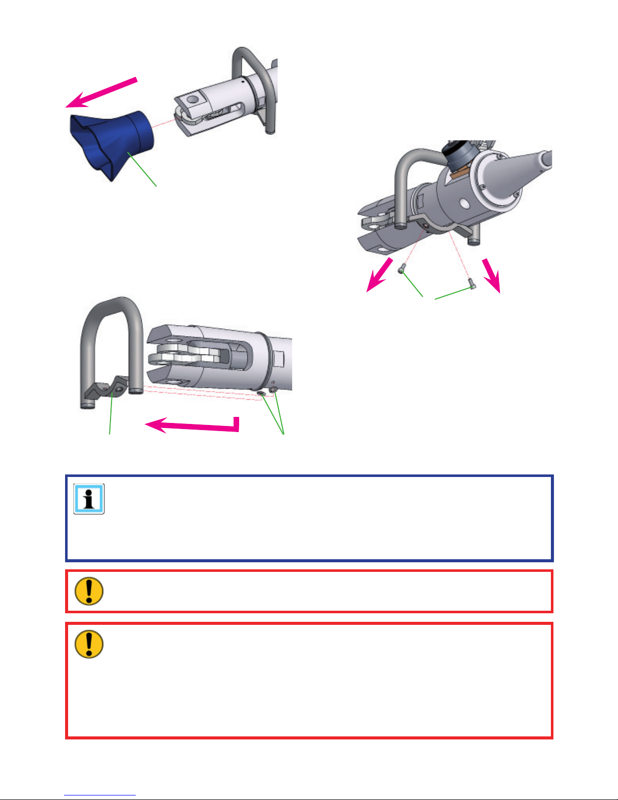
If only the blade arms need replacing, follow the procedure as far as Step 6 and
then go on to Step 11.
If the protection hose needs changing, follow the procedure as far as Step 8 and
then go on to Step 11.
CAUTION!
Don’t forget to apply HURST special grease to all sliding surfaces.
8. Finally, remove the protection hose ‘H’ from
the tool as shown.
9. Unfasten the screws ‘J’ and remove them.
10. Take the handle ‘K’ away in direction of the
lever elements and also remove the washers
‘L’ underneath.
11. Assembly is carried out in the reverse order.
J
LK
CAUTION!
A special process is used to match the pivot bolt and the self-locking nut. When
replacing, therefore, always exchange both the pivot bolt and the self-locking nut
for a new pair! Because of the special procedure an unscrewing of the nut while
working will be minimized and a resulting blade crack will be prevented.
The nuts can be unscrewed and retightened up to 10 times without affecting
service performance!
Page 19

19
9.3.2 Labels
All damaged and/or illegible labels (safety notices, type plate, etc.) must be renewed.
Procedure:
1. Remove damaged and/or illegible labels.
2. Clean surfaces with industrial alcohol.
3. Attach new labels.
Ensure that you attach the labels in the right position. If you are no longer sure about this,
then please contact your authorised HURST dealer or HURST itself.
10. Troubleshooting
Problem Check Cause Solution
The blade arms cannot be
fully opened or closed
Insuffi cient hydraulic
fl uid in the tool
Repair by an
authorised dealer,
by personnel
specially trained
by HURST, or by
HURST itself
Tool does not deliver the
specifi ed power
Device defective
The blade arms move
under load independent
without operating the
hand pump
Device defective
Slow movement of the
blade arms when pumping
in the off-load condition
More than 45 pump
strokes required to
open or close the
device?
Device defective
Rotary knob on the control
valve diffi cult to turn under
load conditions
Device defective
The leaking of hydraulic
fl uid from the pump lever
or from the blade arm
piston rod
Defective piston rod
seal
Damage to the
piston
Material to be cut slides
between the blade arms
during cutting
Check pivot bolt Pivot bolt not
tightened with the
prescribed torque
Tighten the pivot
bolt.
Tool head cannot be
turned
Tool under pressure Depressurise the
tool
Page 20
20
If it is not possible to remedy the malfunctions, inform an authorised HURST dealer or the
HURST Customer Service department directly!
The address of the HURST Customer Service Department is:
HURST
JAWS OF LIFE, INC
A Unit of IDEX Corporation
711 N. Post Road
Shelby, NC 28150 USA
Phone: (704) 487-6961
Fax: (704) 487-7271
e-mail: [email protected]
11. Technical data
11.1 Combi tools
Since all values are subject to tolerances, minor differences may occur between the data
on your device and the data in the following schedules! The values can also differ due to
reading inaccuracies and/or the tolerances of the measuring equipment used.
NOTE:
The following tables contain only the technical data required for standard
acceptance.
Additional data concerning your unit can be obtained from HURST on request
Type SC 250 M
Ref. no. 273055000
Dimensions
(l x w x h)
[mm] 850 x 190 x 158
[in.] 33.47 x 7.49 x 6.23
max. cutting opening
[mm] 225
[in.] 8.9
max. cutting force
(rear end of the cutting
surface)
[kN] 261
[lbf.] 58,673
max. spreading distance
(on the blade tips)
[mm] 308
[in.] 12.1
max. spreading force
(25mm from the tips)
[kN] 34
[lbf.] 7,643
Mass incl. hydraulic fl uid
[kg] 11,9
[lbs.] 43.7
Cutting classifi cation acc.
to NFPA 1936
A6/B6/C6/D7/E7
Page 21
21
Cutting material
Cutting material
dimensions
SC 250 M
max.
[mm]
[in.]
Round material steel
(acc. to EN 13204)
26
1.02
11.2 Pivot bolt tightening torques
11.3 Cutting performance
11.4 Temperature ranges for operating and storage
Operating temperature [°C] / [°F] -20 … +55 -4 … +131
Ambient temperature
(device in operation)
[°C] /
[°F] -25 … +45 -13 … +113
Storage temperature
(device not in operation)
[°C] /
[°F] -30 … +60 -22 … +140
Type SC 250 M
Pivot bolt M24 x 1,5
Wrench size
[mm] 36
[in.] 1.42
Torque
[Nm] 100 +10
[lbf.in.] 885 + 89
Page 22

22
12. EC declarations of conformity
Page 23

23
13. Notes
Page 24

SC250M_unitool_manual_273055085_en.indd
Subject to revision
Please dispose of all packaging materials and
dismantled parts properly
HURST
JAWS OF LIFE, INC
A Unit of IDEX Corporation
711 N. Post Road
Shelby, NC 28150 USA
Phone: (704) 487-6961
Fax: (704) 487-7271
E-mail: [email protected]
Copyright 2014 Hurst Jaws of Life, INC
 Loading...