

Page 1
Installation Instructions
Lockout Sleeve
Indy Stick
Thread Lock
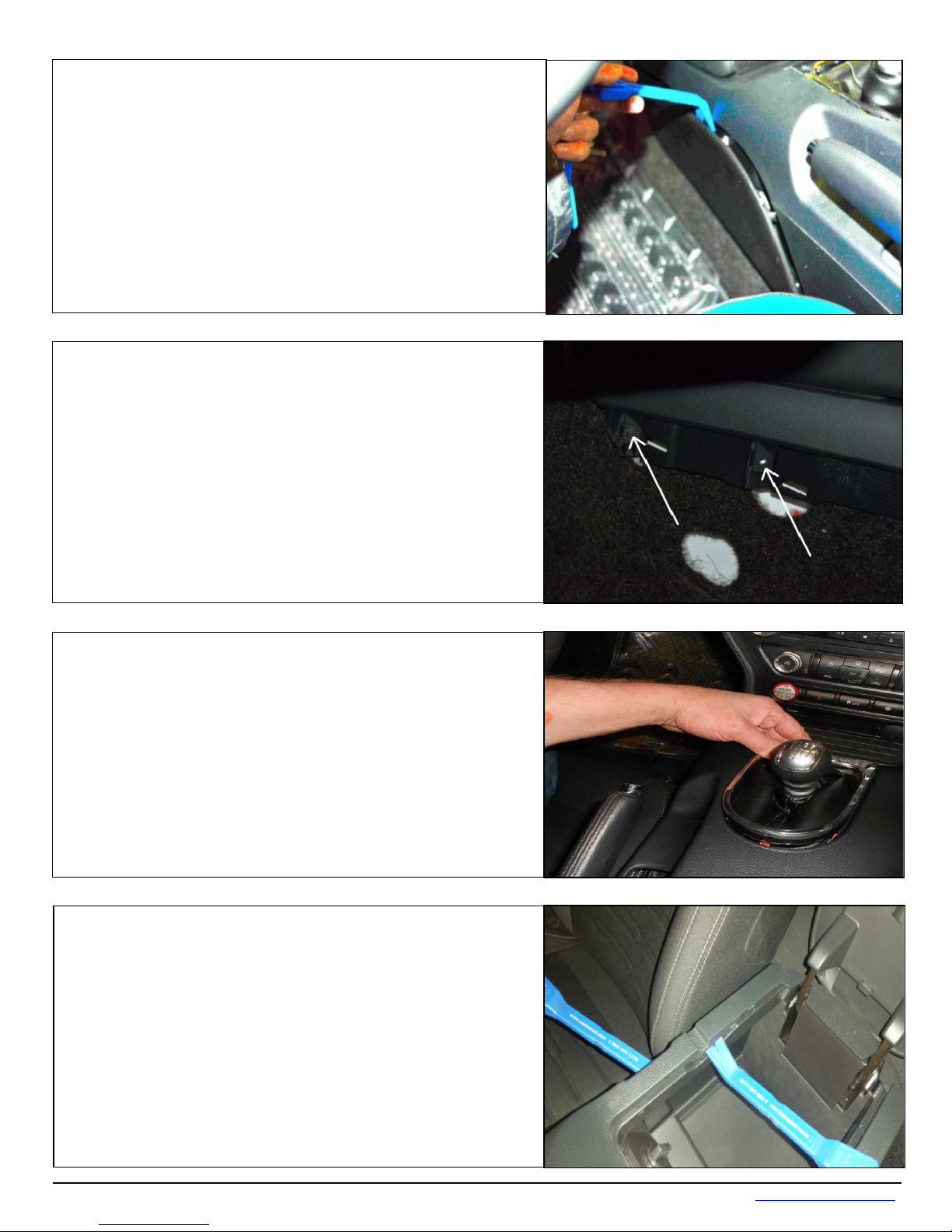
1. Unscrew the shif t knob.
Grease Packet
Knob
Rear Bushing
Watch our
Fits: 2015-2018 Mustang Fastback & Convertible
WORK SAFELY! For maximum safety, perform this installation on a clean, level surface and with the
engine turned off. Place blocks or wedges in front of and behind both rear wheels to prevent
movement in either direction.
CAUTION: To avoid any possibility of bodily injury or damage to vehicle, do not attempt installation
until you are confident that the vehicle is safely secured and will not move.
(counter-clockwise to remove.)
Technical Support (707) 544-4761 1 www.HURST-SHIFTERS.com
INDY SHIFTER
with MT-82 Transmission
Catalog # 3916036
PARTS
installation video
on YouTube
Page 2
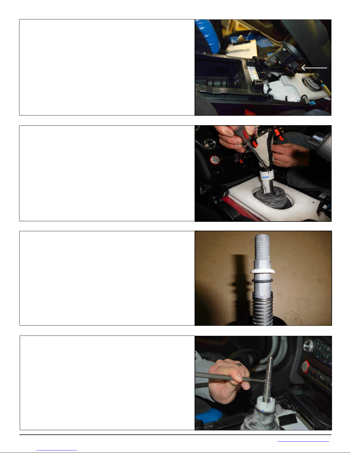
2. Remove the front driver side and passenger side
3. Remove the two (2) screws from both sides of the
4. Unsnap the shift boot bezel from the console. Lif t from
5. Remove the center console. Start by releasing the
locking tabs at the rear of the console while working
panels from the center console.
Tool: Plastic Trim Remover
console.
Tools: 7mm Socket, Extension, Ratchet
the top to release the top clips and then use the pry tool
to un-clip the rest.
Tool: Plastic Trim Remover
your way forward.
Tool: Plastic Trim Remover x 2
Technical Support (707) 544-4761 2 www.HURST-SHIFTERS.com
Page 3
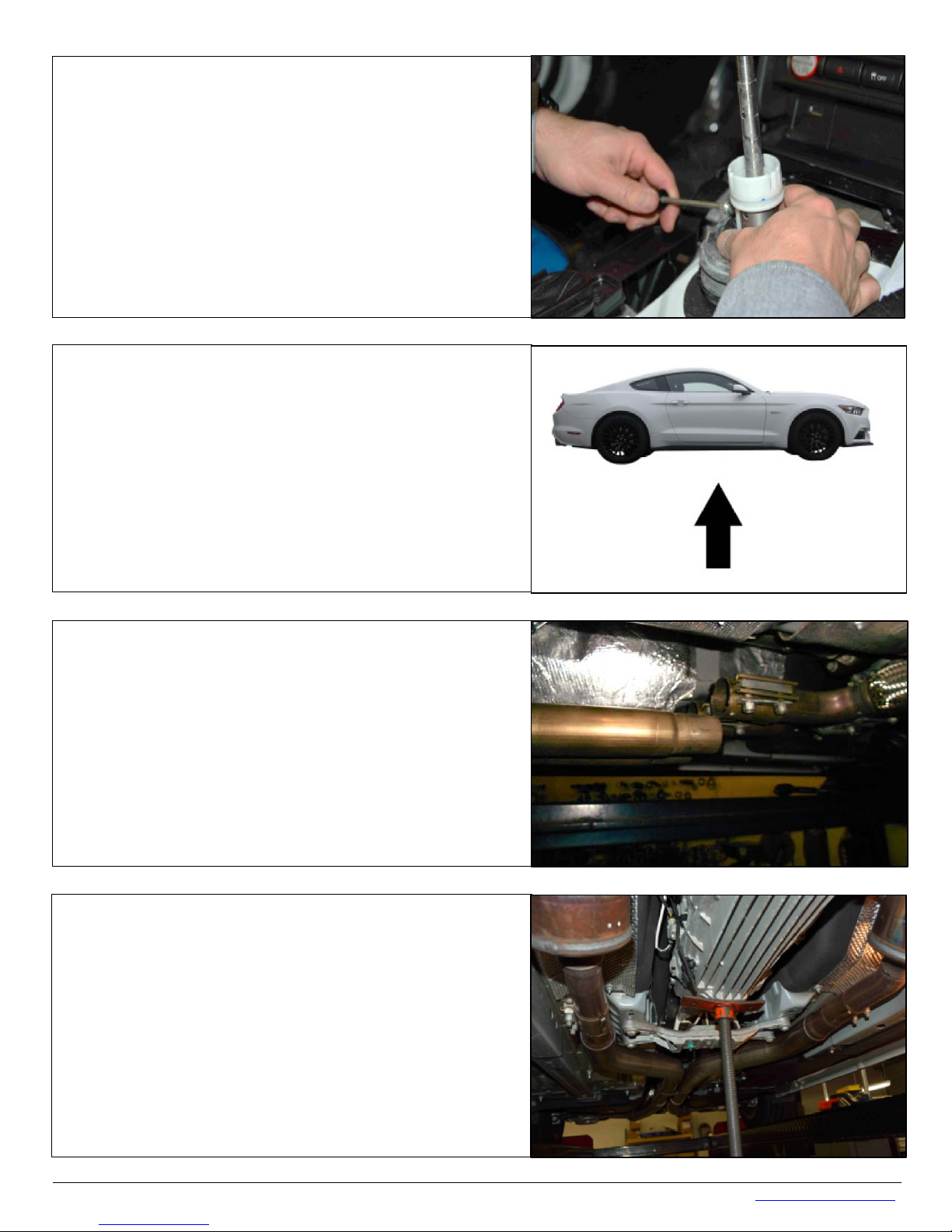
6. Unplug the harness from the console and set the
7. Remove the shift boot. There are three clips holding
lock out sleeve, use a screw
driver to pry one clip at a time while pulling up on the
8. Once the rubber boot is removed continue by
9. Remove the spring retaining roll pin and the spring.
console aside.
the boot to the reverse
boot. Set the boot aside for reinstallation later.
removing the plastic ring and the rubber O-ring. The
plastic ring and rubber O-ring will be re-used .
The spring will be reused.
Tools: 4mm Punch, Hammer
Technical Support (707) 544-4761 3 www.HURST-SHIFTERS.com
Page 4
10. Remove the retaining screw and then remove the
11. Lift the vehicle. Support the vehicle with
12. Although this step is not required it makes for ease
Loosen the nuts at the two exhaust
connections just behind the transmission. Move the
13. Support the transm i s si on.
factory reverse lockout sleeve and rubber boot. The
retaining screw and rubber boot will be reused.
Tool: T20 Torx Driver
Jackstands if working with a floor jack.
of removal and installation. Support the mid-section of
the exhaust.
system to the rear and let the system hang in place.
Tools: 15mm socket
Tools: transmission stand or floor jack
Technical Support (707) 544-4761 4 www.HURST-SHIFTERS.com
Page 5
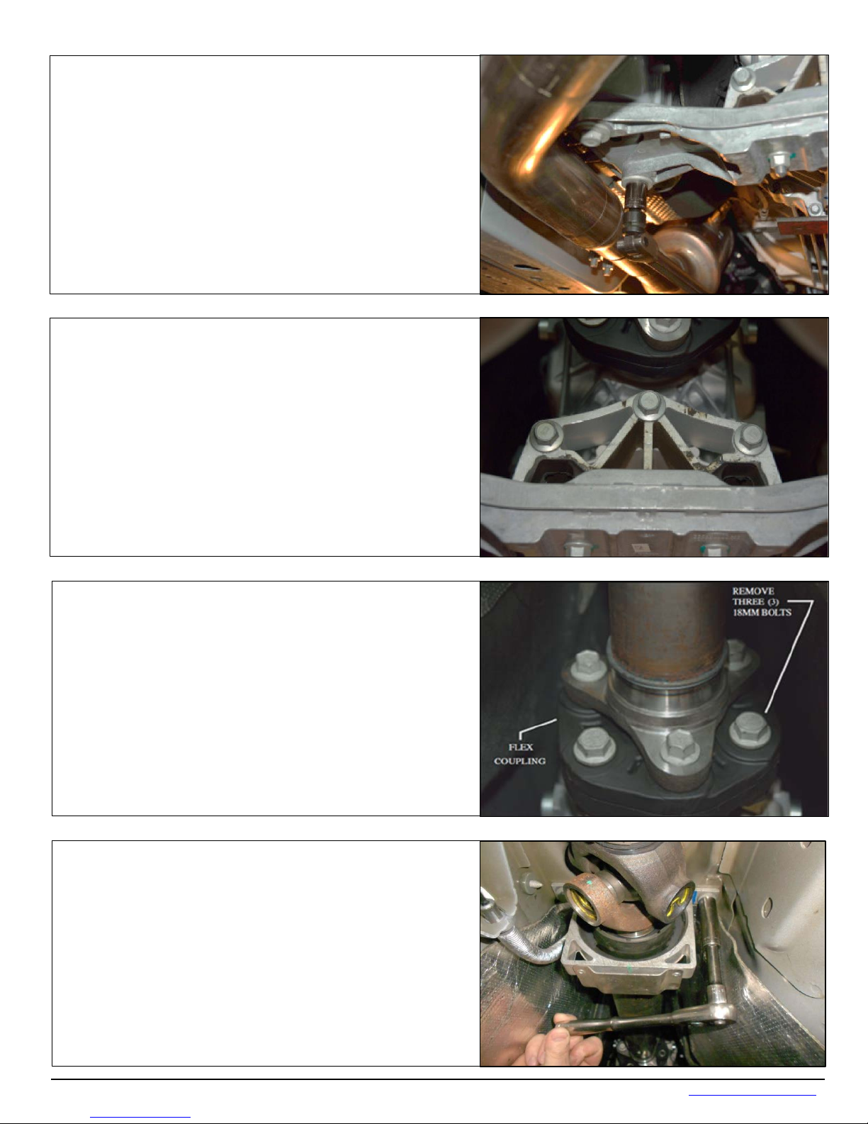
14. Remove the four (4) 18mm bolts securing the
support the rear with a floor jack if you have the
15. Remove the three (3) 15mm bolts securing the
16. Remove the three (3) 18mm bolts securing the
17. Remove the center bearing bolts.
transmission to the frame. Lower the rear of the
transmission. Support the rear with a transmission
stand if you have the vehicle supported with a lift;
vehicle supported with jack stands.
Tools: Breaker Bar, 18mm Socket, Ratchet, Extension
crossmember to the transmission.
Tools: Breaker Bar, 15mm Socket, Ratchet
front end of the driveshaft to the transmission.
IMPORTANT: Make an alignment mark between the
Flex Coupling and the transmission flange. You must
re-install the driveshaft in the same position as it was
removed.
Tools: 18mm Socket, Ratc het
Tools: 13mm Socket, Ratc het
Technical Support (707) 544-4761 5 www.HURST-SHIFTERS.com
Page 6
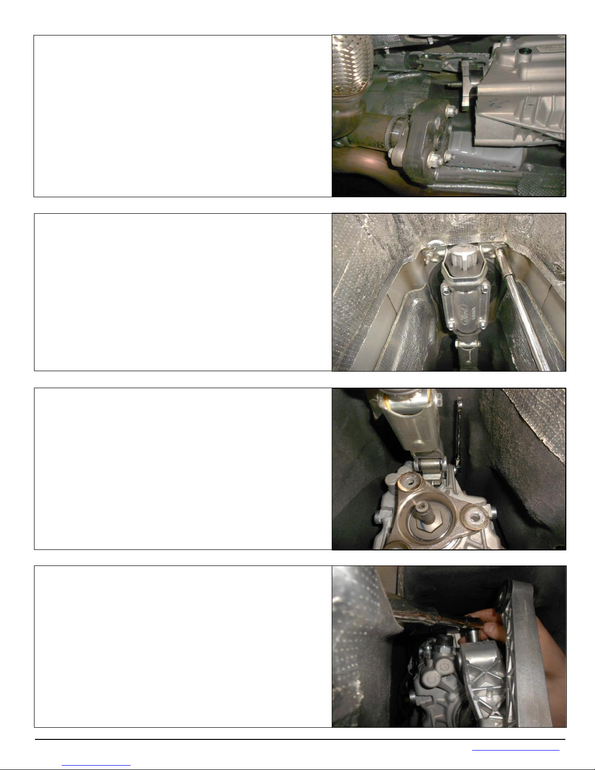
18. Once the center bearing bolts have been removed,
19. Remove the two (2) 10mm hex nuts that mount the
20. Remove the bolt attaching the shifter housing to
for ease of
Remove the bolt from the side of the transmission.
to pull down on the transmission to
21. Remove the shift linkage bolt.
you can pull the driveshaft back and lower the front
end of the driveshaft. Allow the driveshaft to rest on
top of the exhaust.
rear of the shifter to the transmission tunnel.
Tools: 10mm Deep Socket, Universal Adapter,
Extension(s), 1/4” Drive Ratchet
the transmission.
Tools: a 10mm ratchet wrench makes
removal.
You may have
allow the screw to clear the tunnel.
Tools: 13m m Socket, 3/8” Drive Ratchet
Technical Support (707) 544-4761 6 www.HURST-SHIFTERS.com
Page 7
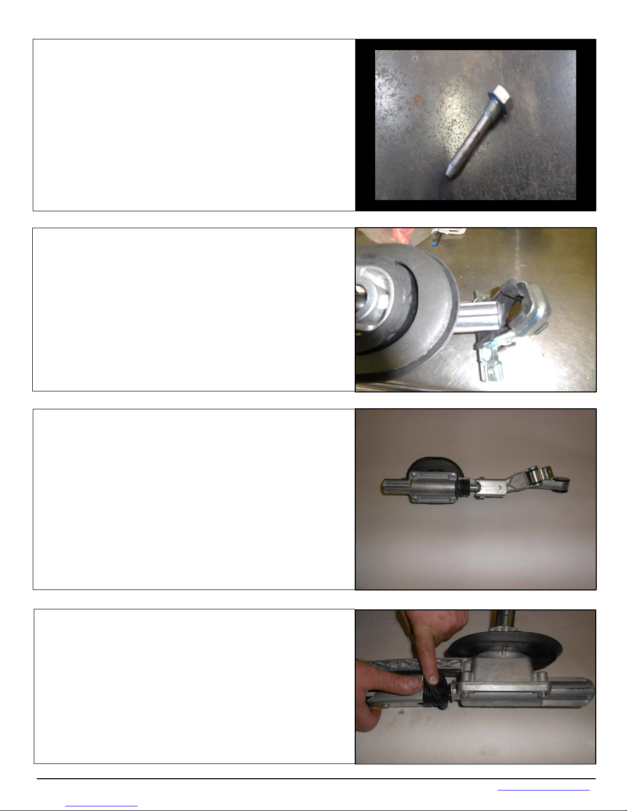
22. The photo to the right is a close up of the bolt
loose. After it is completely
23. The shifter housing assembly can now be removed.
24. Place the shifter housing on a clean surface.
25. Remove the rubber boot from the shifter housing.
removed from the shift linkage. Note that the bolt is only
partially threaded at the top. This is being mentioned so
you don’t spend too much time trying to loosen a bolt
that is already completely
loose, it will need to be pulled free.
Remove the factory rear mount from shifter housing.
Technical Support (707) 544-4761 7 www.HURST-SHIFTERS.com
Page 8
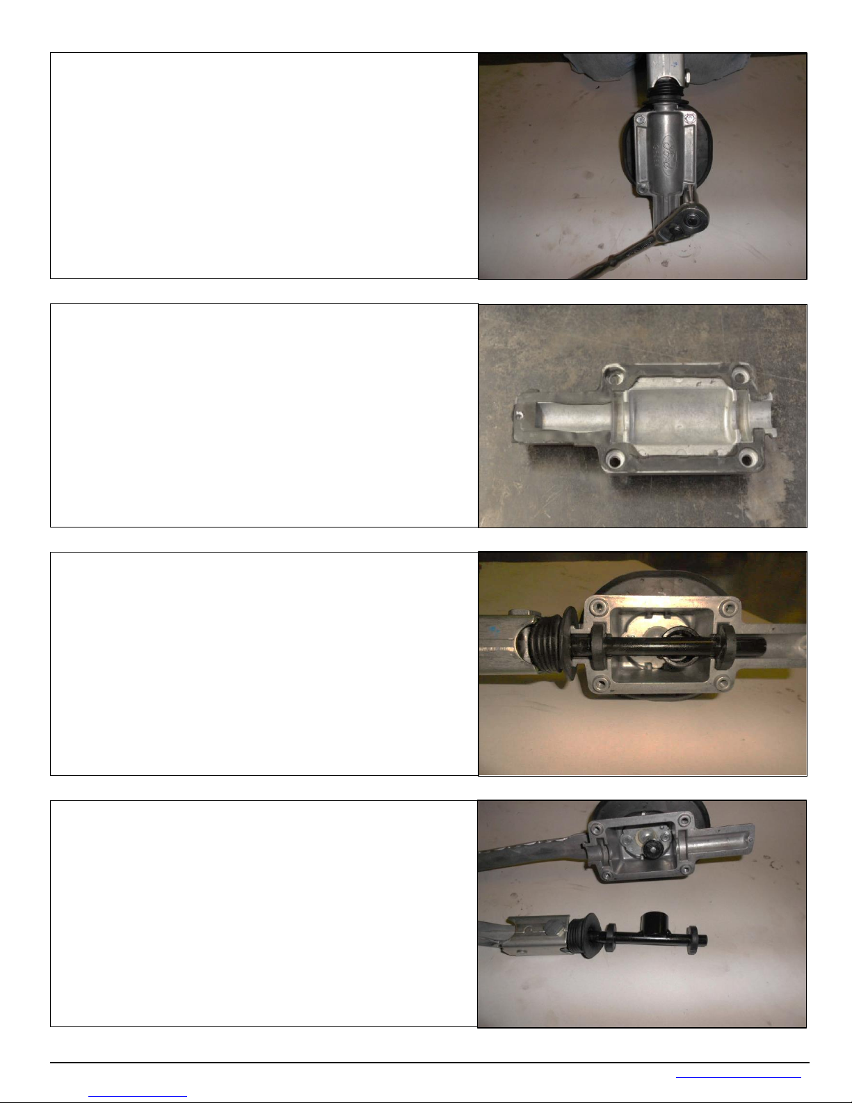
26. Remove the (4) 10mm bolts securing the bottom
27. Remove the bottom Plate. Take care when
there is a rubber gasket
28. This is a photo of what the internal components of
29. Remove the shift rod from the shifter housing.
plate to the shifter housing .
Tools: 10M M Socket
removing the bottom plate,
that will be reused.
the shifter look like.
Technical Support (707) 544-4761 8 www.HURST-SHIFTERS.com
Page 9
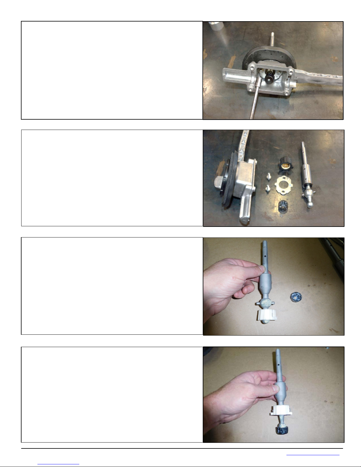
31. Remove the shifter from the housing and
30. Remove the shifter retaining plate from the bottom
32. Apply the provided grease to the large factory pivot
cup and snap it into place on the large ball portion of
33. Apply the provided grease to the small factory pivot
cup and snap it into place on the small ball portion of
of the shifter housing.
Tools: 10mm Socket, Extension, Ratchet
disassemble. Use a set of pliers to pry the sm all pivot
cup off of the small pivot ball. T he larger pivot cup can
be removed by hand. The large pivot cup, small pivot
cup, screws and the plate will be re-used.
Tool: Pliers
the Indy Shifter.
the Indy shifter stick.
Technical Support (707) 544-4761 9 www.HURST-SHIFTERS.com
Page 10
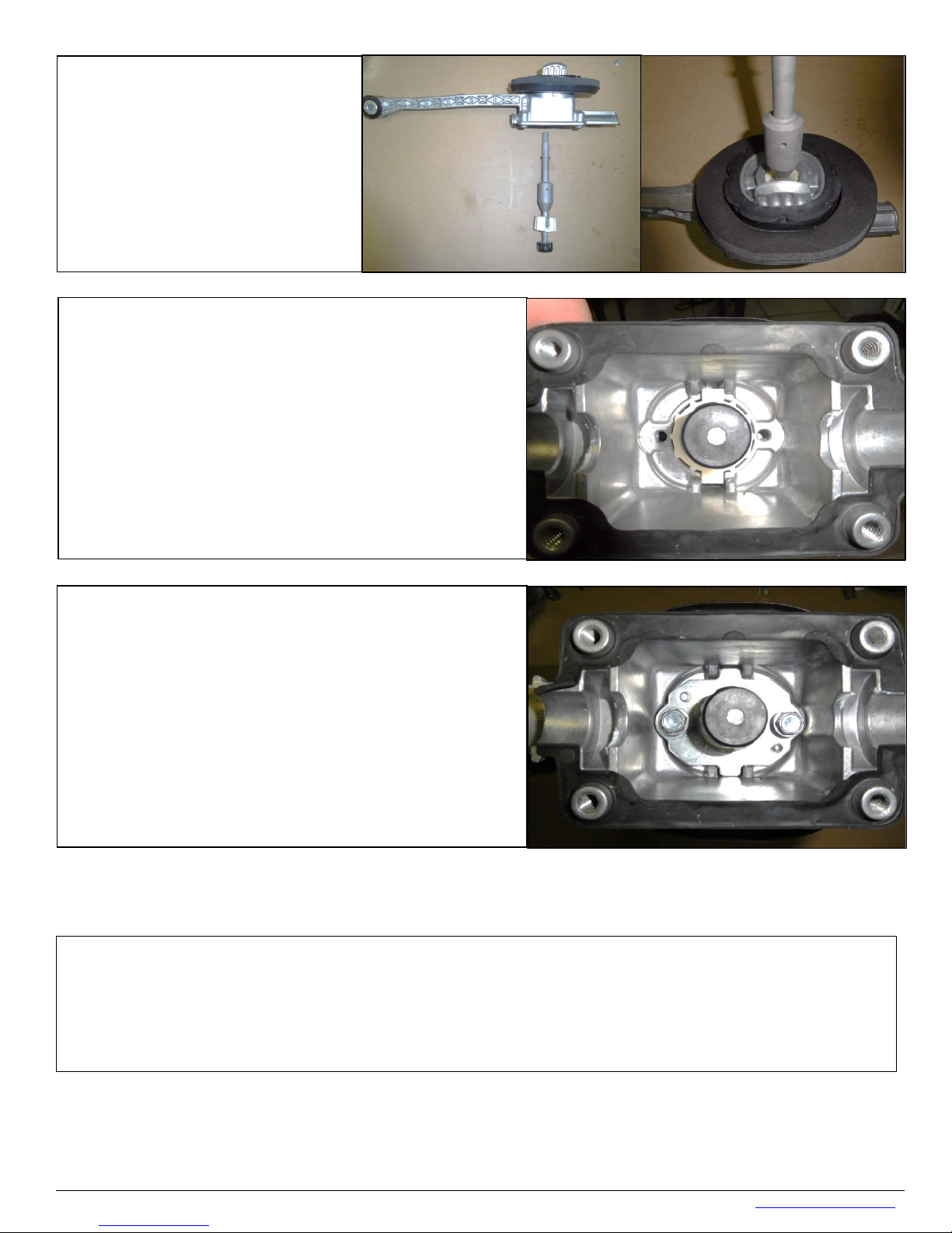
34. Install the Indy shifter into the
factory housing. The threaded
hole on the large portion of the
left side of the shifter housing
35. Seat the large pivot cup aligning the two tabs to
the two recessed slots in the bottom of the shifter
36. Reinstall the shifter retaining plate. The plate
should seat flat against the bottom of the shifter
reinstall the factory shift rod and
torque all bolts to factory torque specifications
Indy shifter must be orientated to
looking forward.
housing.
housing. Torque to the factory specifications.
Working in reverse order from step 29 to 24,
assemble the shifter housing. Reapply grease to all pivot points.
Technical Support (707) 544-4761 10 www.HURST-SHIFTERS.com
Page 11
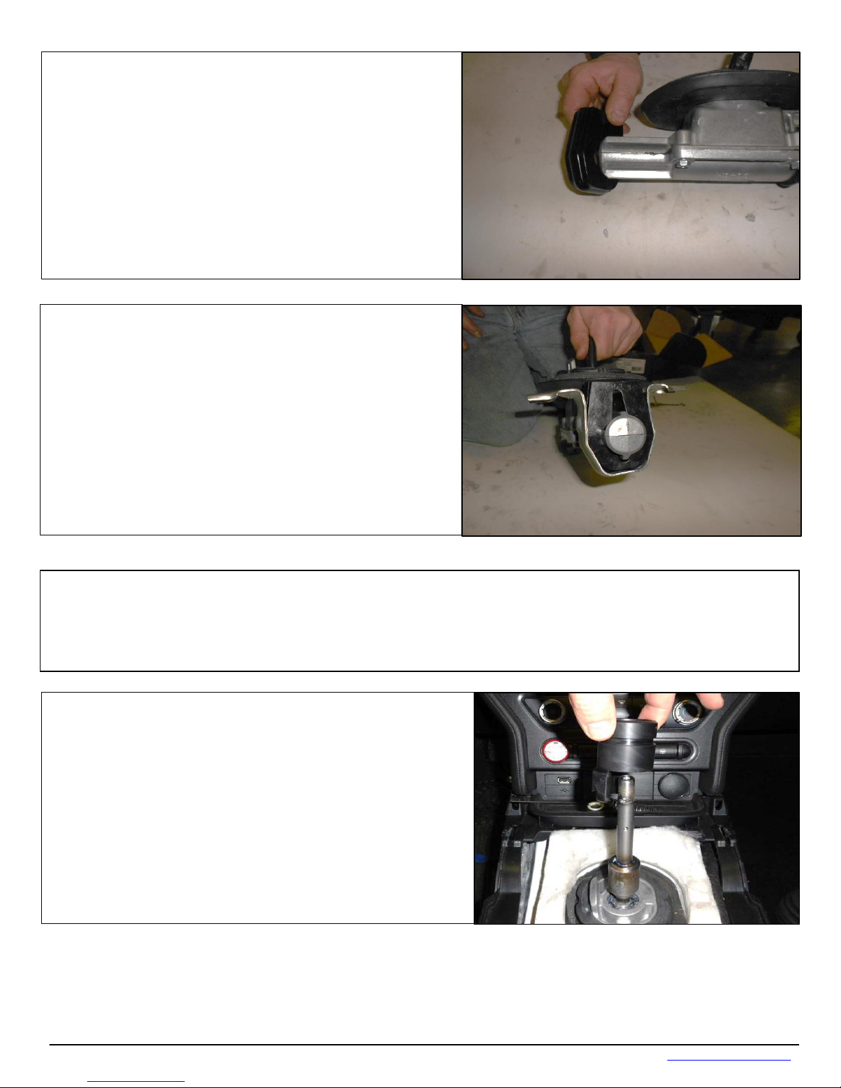
37. Install the new polyurethane bushing supplied with
38. Insert it into the bracket clip. You will need to form
the clip bracket around the new bushing to make it
easier for install. The holes need to be 4.21 inches
to compress the assembly during
40. Working from the inside of the vehicle slide the new
39. Working in reverse order step 21 through step 11, reinstall the shifter housing
the kit.
apart to be re-installed. It will be improbable that you
will get it to hold at 4.21 inches apart, but try to get it
close to 4.21 inches as possible. You will rely on a pair
of channel locks
install.
assembly, driveline, crossmember and exhaust if undone. Re-torque all bolts to factory
torque specifications.
reverse lockout down over the Indy shifter. This is a dry
install no grease is required.
Technical Support (707) 544-4761 11 www.HURST-SHIFTERS.com
Page 12
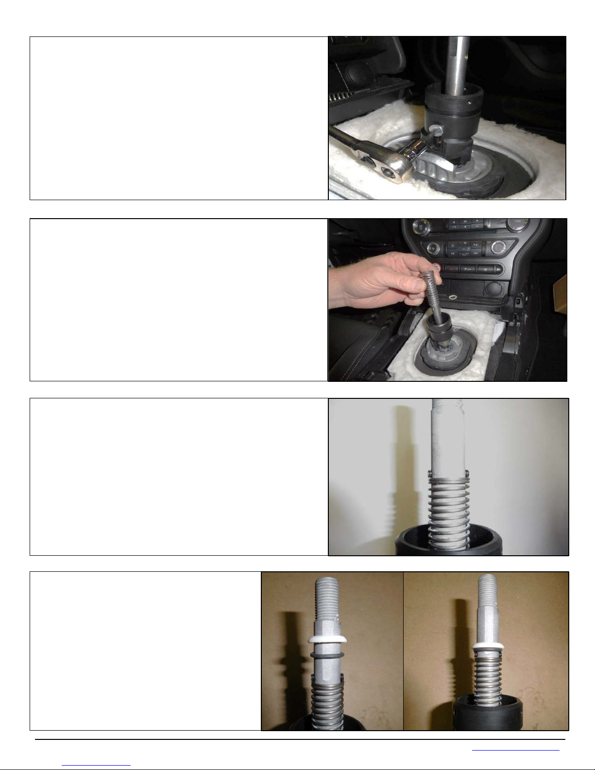
41. Align the reverse lockout block to the threaded
retaining screw that was removed in step 9 to secure
Indy stick while allowing the reverse lockout to freely
43. Compress the spring enough to install two of the
provided set screws. Install the set screws evenly
44. Reinstall the O-ring and plastic ring
42. Reinstall the factory spring that was removed in
hole on the larger portion of the Indy shifter. Use the
the reverse lockout into position.
Note: The retaining screw should tighten down to the
move up and down.
step 8.
tightening them against each other.
that were removed in step 7.
Technical Support (707) 544-4761 12 www.HURST-SHIFTERS.com
Page 13
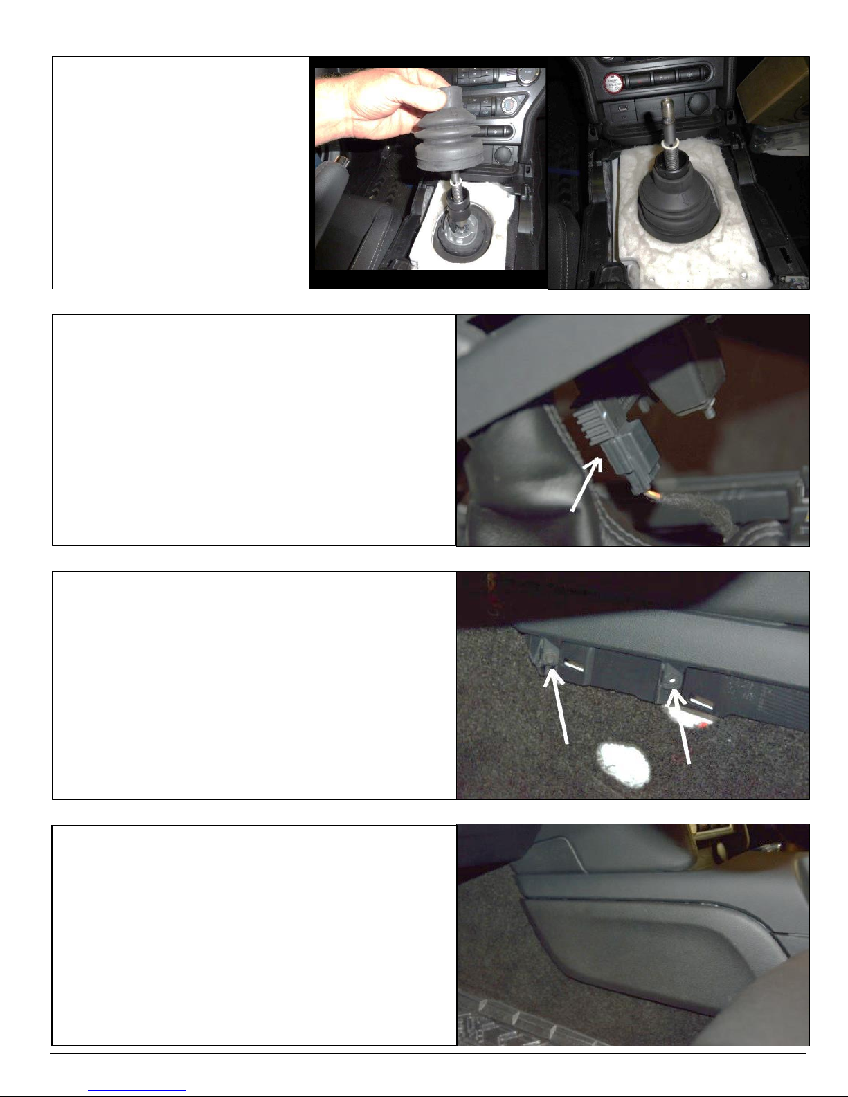
45. Reinstall the rubber boot
slide it down over the reverse
the boot will
slide down into the machined
47. Re-install the two (2) screws on both sides of
46. Reinstall the center console.
vehicle will not start if the harness is not
48. Re-install the front driver side and passenger
lockout. Seat the bottom of the
boot on the shif ter housing. The
upper portion of
groove on the reverse lockout.
NOTE: Do not forget to re-connect the harness. The
reconnected.
the console.
Tool: 7mm Socket, Extension, Ratchet
side panels from the center console.
Technical Support (707) 544-4761 13 www.HURST-SHIFTERS.com
Page 14
``
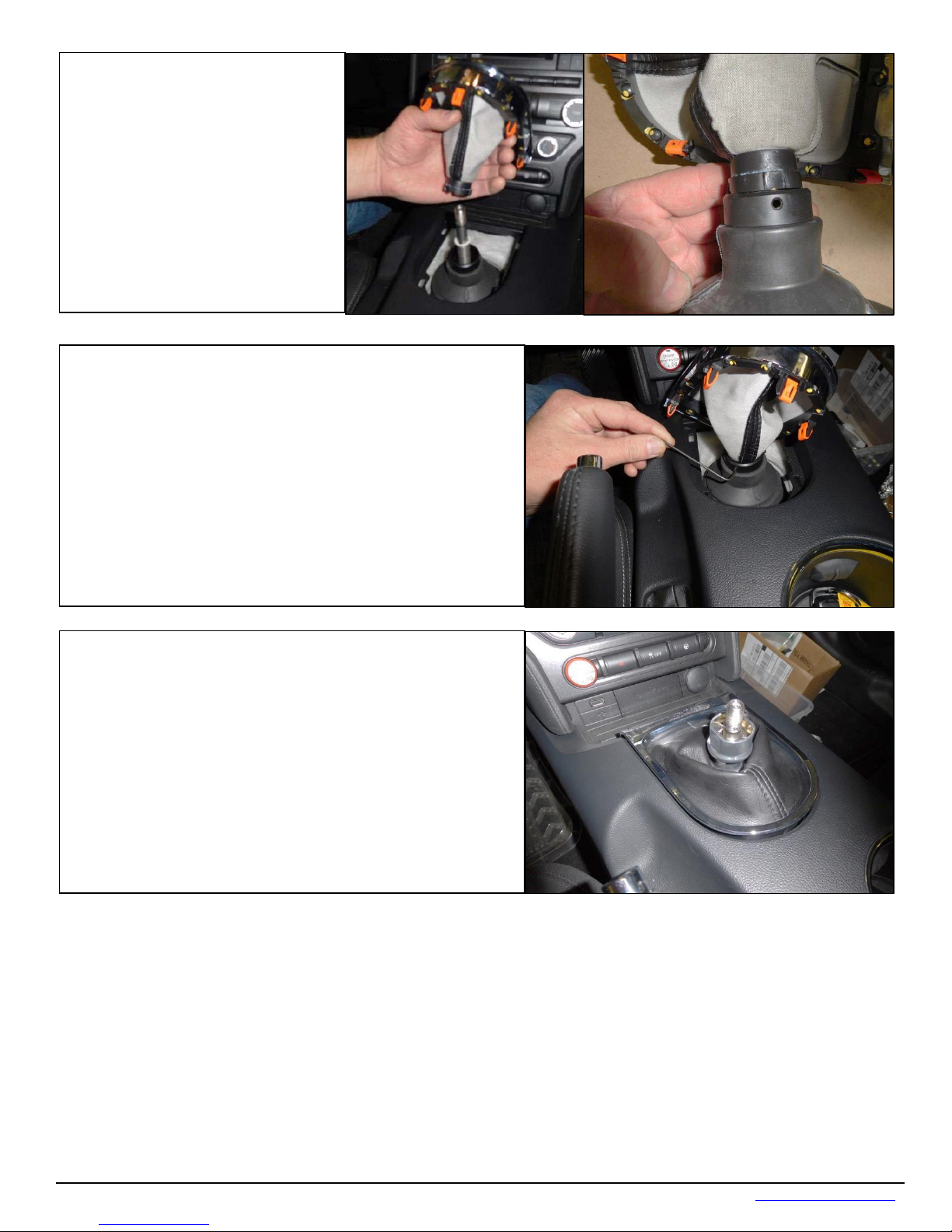
49. Install the factory shift boot
50. Install the three supplied set screws and evenly
51. Snap the chrome bezel back in place.
onto the reverse lockout. There
are three threaded holes in the
upper portion of the lockout
align the notches on the shift
boot to the holes on the
reverse lockout and push the
shift boot down into place.
tighten the shift boot into place.
Technical Support (707) 544-4761 14 www.HURST-SHIFTERS.com
Page 15
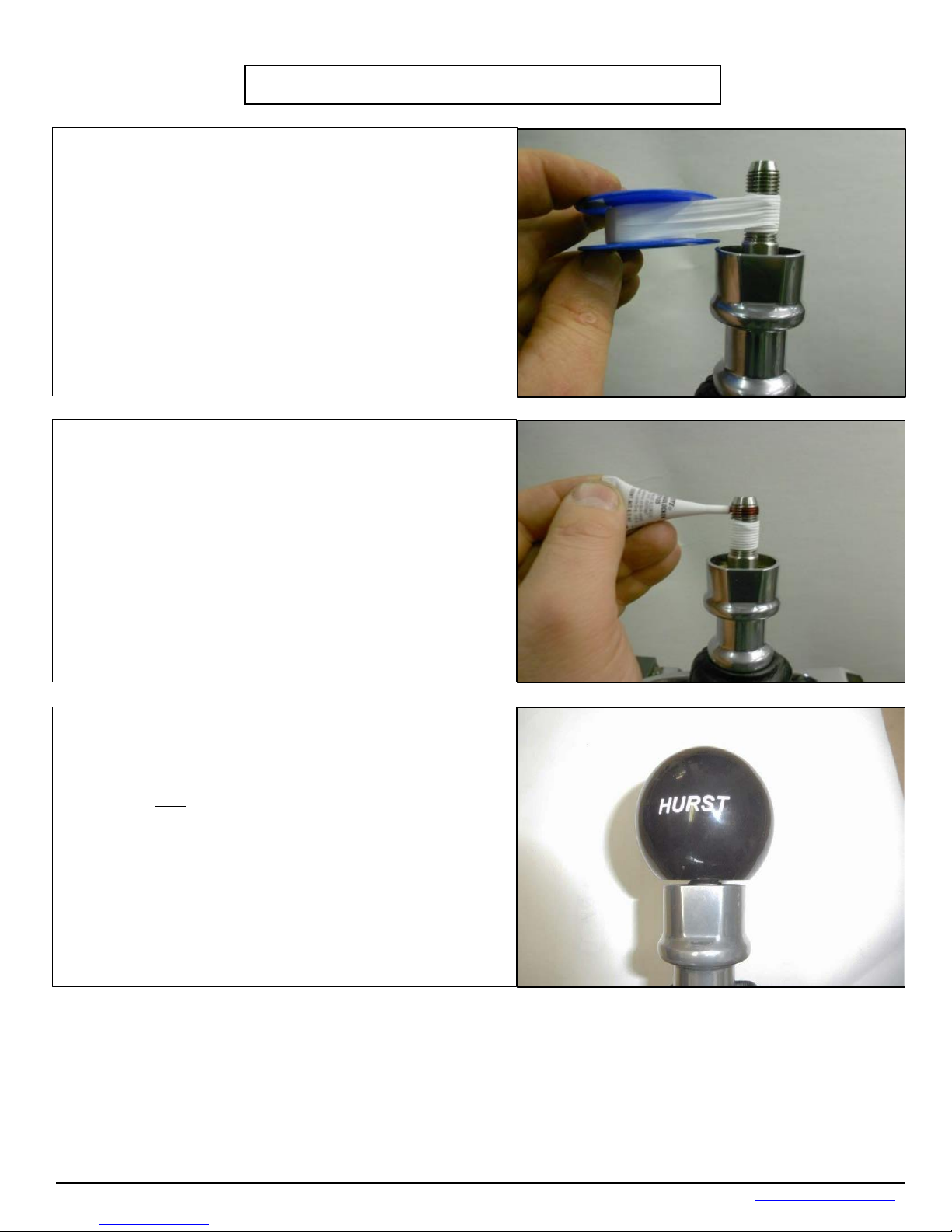
Shift Knob Installation
52. Apply ten full wraps of ½” wide Teflon thread tape
53. Apply the included LOCTITE® 271 thread lock
54. Screw knob onto handle until the bottom of the
knob is just even with the top of the lockout collar
(see photo). Continue to screw the knob an
turn plus whatever is necessary to
crewing the knob on too far can prevent
proper operation of the lockout collar and could
on the threaded handle. Leave approximately 3/8” of
exposed threads above the tape as shown in picture.
compound to the threaded portion above the Teflon
tape.
additional one
align the shift pattern/logo properly.
Note: S
cause damage to the knob.
Technical Support (707) 544-4761 15 www.HURST-SHIFTERS.com
Page 16
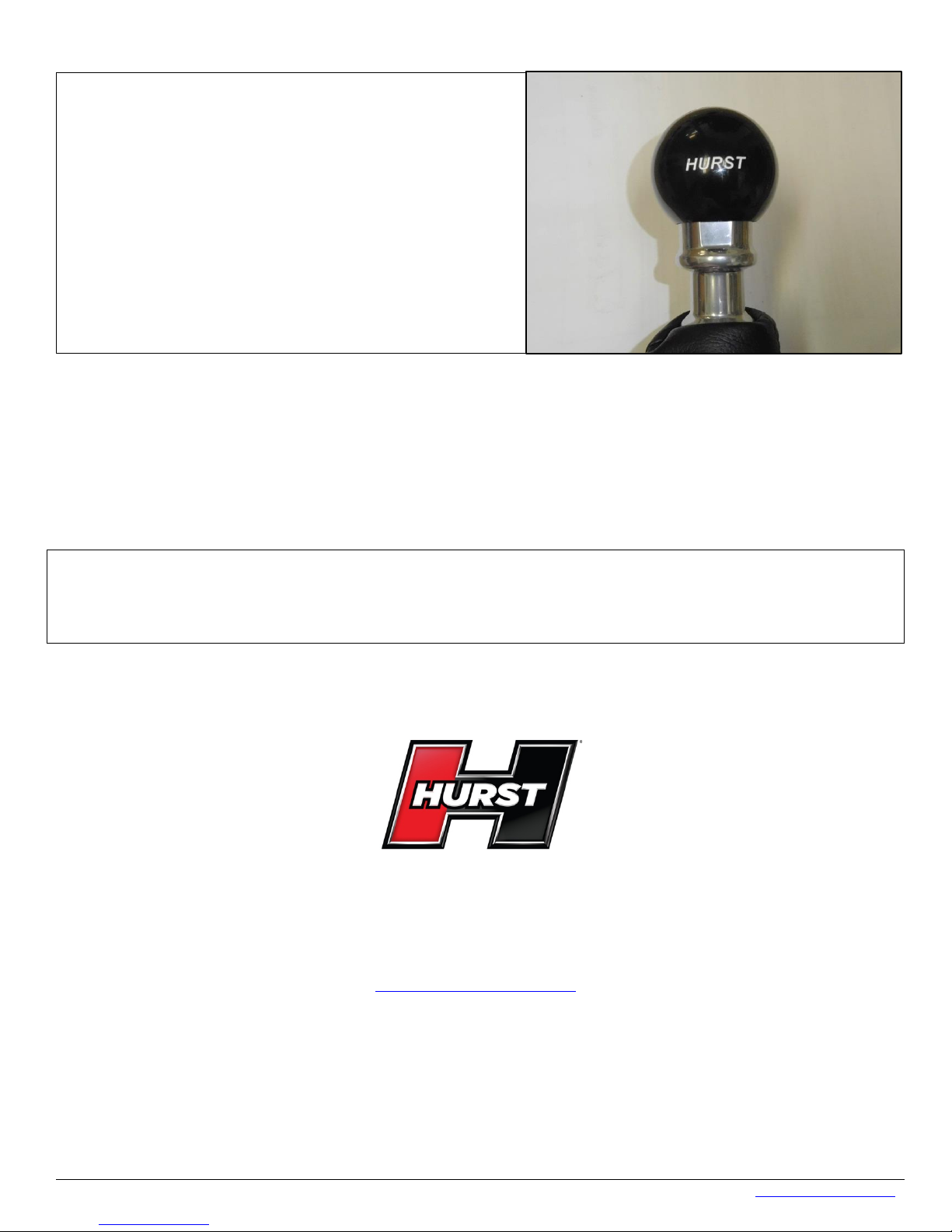
55. Check for proper operation by engaging the
reverse lockout and making sure the shifter will go
into reverse.
IMPORTANT
Once this is confirmed, Avoid driving/shifting the
vehicle for 1-2 hours. The LOCTITE® will set in
approximately 10 minutes, but will not fully cure
for 24 hours.
IMPORTANT: RETAIN THESE INSTRUCTIONS FOR FUTURE REFERENCE
Technical Service
A highly trained technical service department is maintained by Hurst Performance to answer your
technical questions, provide additional product information and offer various recommendations.
Technical service calls, correspondence, and warranty questions should be directed to:
Hurst Performance Products
(707) 544-4761
www.Hurst-Shifters.com
Technical Support (707) 544-4761 16 www.HURST-SHIFTERS.com
 Loading...