

Page 1

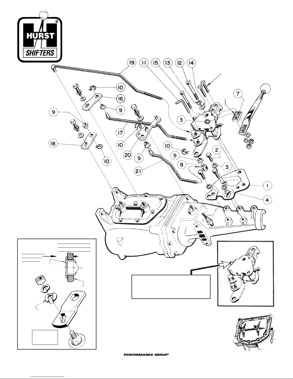
1. MOUNTING PLATE Pt. 195 8008
2. 3/8 - 16 x 3/4 HEX HEAD CAP SCREW Pt. 96000540 (3)
3. 3/8" INTERNAL TOOTH LOCKWASHER Pt. 267 3533 (4)
4. 3/8" FLATWASHER Pt. 97090058
7. SPACER BLOCK Pt. 228 8397
8. ROD ADJUSTING BUTTON Pt. 119 3783 (3)
9. BUSHING Pt. 118 1681 (6)
10. SPRING CLIP Pt. 97000015 (6)
1 1. NEUTRAL ALIGNMENT GAGE Pt. 148 1725
12. 7/16 - 20 x 3 HEX HEAD CAP SCREW Pt. 215 2343
13. 7/16" SPLIT LOCKWASHER Pt. 97000404
ATTENTION
Due to var iations in auto manufacturing
tolerances, the transmission rods supplied with this kit may require slight
bending to clear obstructions, etc.
Protect the threads
while bending.
BEND RODS COLD!
DO NOT APPLY HEAT!
WARNING
THIS TRANSMISSION DOES NOT HAVE AN INTERLOCK TO PREVENT ENGAGEMENT OF THE REVERSE GEAR WHEN ANY OF THE FORWARD GEARS ARE
ENGAGED. SEVERE DAMAGE TO THE TRANSMISSION WILL RESULT IF THIS
SHOULD OCCUR. DOUBLE-CHECK THE LINKAGE BEFORE STARTING THE ENGINE
OR MOVING THE CAR. INSERT NEUTRAL ALIGNMENT ROD (Pt. 1725) THROUGH
LEVERS AND CHECK POSITIONS OF TRANSMISSION SHIFTING ARMS. 1-2 AND
3-4 TRANSMISSION CONTROL ARMS MUST BE AT NEUTRAL POSITIONS OF
THEIR TRAVEL. REVERSE GEAR CONTROL ARM MUST BE AT FORWARD END OF
ITS TRA VEL (DIS-ENGAGED).
14. 7/16" FLATWASHER Pt. 96000561
15. 3/8 - 24 x 2 3/4 HEX HEAD CAP SCREW Pt. 215 3459
16. ARM 1–2 Pt. 105 7058
17. ROD 1–2 Pt. 213 0046
18. ARM 3–4 Pt. 105 7060
19. ROD 3–4 Pt. 213 2145
20. ARM REVERSE Pt. 105 7061
21. ROD REVERSE – Muncie Pt. 213 2146
21. ROD REVERSE – Borg-Warner Pt. 213 4147
BAGGED HARDWARE Pt. 154 0070
Also included –
Arm Adapter Pt. 101 0006 (3)
CONTENTS OF KIT
91 159 0 089 02 ©1975 by HURST PERFORMANCE, INC.
COMPETITION/PLUS
®
U.S. PATENT NO. 3,216,274 & NO. 3,306,126
INSTALLATION INSTRUCTIONS
Cleveland, Ohio
216.688.8300
www.mrgasket.com
373 8611
391 7992
(shown)
1. Raise vehicle and support it with safety-approved jackstands.
Remove stock shifter and linkage. Remove the two bolts that
fasten the transmission extension housing to the crossmember
at the rear support. The transmission can be moved to the right
side to gain clearance for installation of the mounting plate and
shifter.
2. Install mounting plate on tailshaft. Tighten all bolts securely.
3. Install shifter onto mounting plate. Tighten mounting bolts.
Return transmission to normal position. Replace crossmember
mounting bolts and tighten them. Remove center console plate.
Install spacer block between stick and shifter. IMPOR
TANT –
CENTER MARK ON SPACER MUST FACE SHIFTER (toward
driver). Tighten stick mounting bolts.
4. Assemble hooked ends of rods into arms with nylon bushings
and spring clips. Refer to exploded Assembly View for proper part
combinations. Spin rod adjusting buttons onto threaded ends of
rods. Spin them onto middle of thread length.
5. MUNCIE TRANSMISSIONS – Install arm/rod/button assemblies
onto transmission shafts. Refer to Assembly View for proper part.
Fasten arms onto shafts with stock washers and bolts.
BORG-WARNER TRANSMISSIONS – Insert shaft adapters
(Pt. 101 0 0 06) into slots in arms (refer to FIG. 1). Use stock lockwashers and nuts to fasten arms.
REVERSE ARM ONLY
– The tangs of the adapter must be filed
shorter to allow the Reverse arm to be fastened. Place adapter in
arm slot and file ends flush to surface of arm as shown in FIG. 1.
6. Align levers with shifter frame and insert neutral alignment rod
(Pt. 148 1725) through holes in levers.
7. Rotate transmission arms backward and forward. The neutral
position for each arm can be felt at the mid-position of full travel.
Reverse arm must be moved to the end of its travel toward the
front (dis-engaged position).
8. Adjust positions of button on each rod to permit easy slip-in fit of
button into nylon bushing in proper lever. TRANSMISSION ARMS
MUST REMAIN IN NEUTRAL POSITION WHILE ALIGNMENT IS
ACCOMPLISHED. Fasten buttons in levers with spring clips.
9. Remove neutral alignment rod. Test shifter. Stick should move
freely from side-to-side at neutral (between 1-2 and 3-4
shifting paths). An increased pull toward the operator should
engage the reverse lever. If shifter functions properly, proceed to
paragraph 11.
If the stick CANNOT be moved freely between 1-2 and 3-4 or
reverse path, one or more of the rod button adjustments must be
corrected. Move stick forward to 3rd, then back to 4th, then into
neutral. Insert neutral alignment rod. If rod CANNOT be inserted
freely, the 3-4 button is incorrectly adjusted. Similar testing of
1-2 shift will prove alignment of 1-2 rod adjustment.
To check reverse rod button adjustment, place stick at neutral.
Disconnect reverse rod adjusting button from reverse lever.
Grasp rod and push toward front of car. (Reverse arm is disengaged when at end of forward travel.) Adjust rod button
for easy slip-in fit in bushing. Re-assemble and fasten with
spring clip.
10. Connect BACKDRIVE cable end to pin of HURST Reverse arm.
Fasten with stock hardware.
11. Adjust shifter stop bolts. Back both bolts out of shifter frame
until only a few threads remain engaged. Push stick firmly into
3rd gear and hold. Screw 3rd gear stop bolt in until contact is
felt. Back bolt out one turn and tighten locknut. Pull stick firmly
back into 4th gear, screw 4th gear stop bolt in until contact is
made, then back stop bolt out one turn and tighten locknut.
NOTE: A hole is provided in the reverse arm for the actuating
rod of a GM back-up light switch. If your transmission
is equipped with this switch, hook the switch rod in
this hole.
Page 2
91 159 0089 02 ©1975 by HURST PERFORMANCE, INC.
COMPETITION/PLUS
®
U.S. PATENT NO. 3,216,274 & NO. 3,306,126
INSTALLATION INSTRUCTIONS
Cleveland, Ohio
216.688.8300
www.mrgasket.com
373 8611
391 7992
(shown)
CENTER
MARK
DO NOT REMOVE
TRANSMISSION
2nd & 4th gear stop bolt and jam nut.
Similar bolt and jam nut at rear of
shifter is 3rd gear stop bolt. Refer to
paragraph 11 of text for adjustment.
NOTE:
Muncie transmission is shown in the assembly drawing.
Borg-Warner is recognized by curved bottom side cover
shown in picture to the right. Assembly of all parts is identical to Muncie installation.
FIG. 1
‘74 AND LATER
BORG-WARNER
TRANSMISSIONS
REVERSE
ARM
ADAPTER HELD
FLUSH AGAINST
FACE OF ARM
TANGS
FILE ENDS
FLUSH TO
FACE OF
ARM
FACE OF ARM
ADAPTER
PT. 101 0006
SHAFT ADAPTERS
PT. 101 0006 FIT
INTO SLOTS IN
ARMS AS SHOWN
FILE ADAPTER
IN REVERSE
ARM ONLY
 Loading...