

Hurricane W Instruction Manual
www.hurricane-fans.com
™
www.hurricane-fans.com
™
W Stand Fan
Instruction Guide
Use a “QR Code App” on
your smart phone to access
our website and browse our
entire product offering or go
to: www.hurricane-fans.com
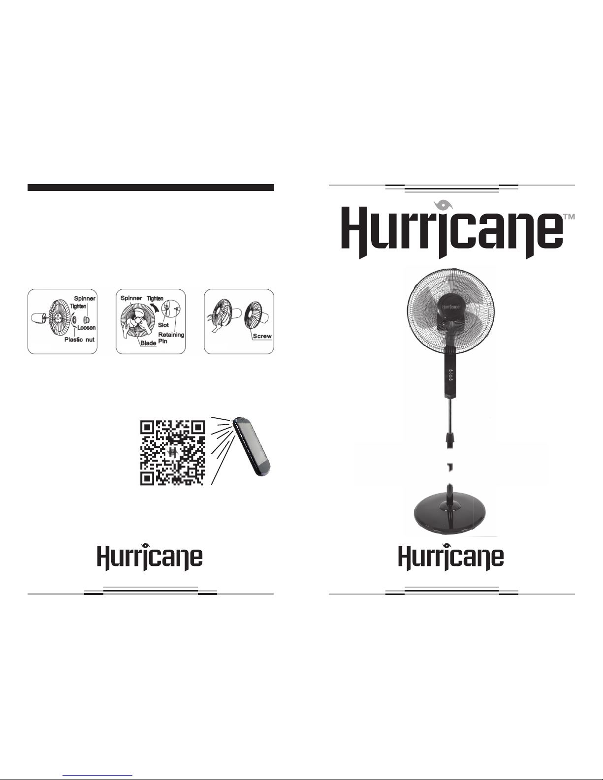
GUARD & FAN BLADE ASSEMBLY
1. Take the spinner from the bag. Then remove the plastic nut by turning it counterclockwise. Place the rear guard to the head unit and
make sure the handle is facing upwards. Screw on the plastic nut
(clockwise), securing the fan guard on the head unit. (See Fig. 7)
2. Discard the small plastic sleeve located on the motor shaft. Install the
fan blade onto the motor shaft. Make sure the fan blade slot fits into
the retaining pin of the motor shaft. Attach the spinner to the motor
shaft by turning it counterclockwise to secure the fan blade. (See Fig. 8)
3. Secure both guards firmly by tightening the fan guard, then fasten
with screws. (See Fig. 9)
Fig. 7 Fig. 8 Fig. 9
SAFETY
CAUTION
Read Rules for Safe Operation and Instructions carefully.
WARNING
1. Read and save these instructions.
2. To reduce the risk of fire or electric shock, do not use this fan with
any solid-state speed control devices.
3. Do not leave the fan running unattended.
4. Please make sure the voltage of the power supply is the same as
shown on the fan nameplate.
5. If the power cord is damaged, it must be replaced by the maker or
authorized service agent or by qualified person to prevent any risk.
RULES FOR SAFETY OPERATION
1. Fan should not exceed rated voltage.
2. Connect power after the fan is fully assembled.
3. Never insert fingers, pencils, or any other object through the guard
when fan is running.
4. Unplug from outlet when not in use, when moving fan from one lo
cation to another, before putting on or taking off parts, and before
cleaning.
5. Disconnect fan when removing grilles for cleaning.
6. Be sure fan is on a stable surface when operating to avoid overturning.
7. DO NOT use fan in window, rain may create an electric hazard.
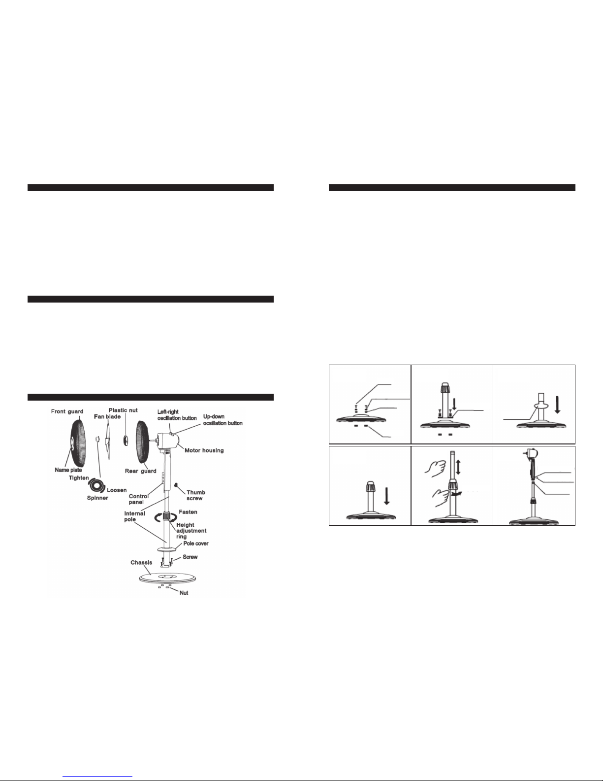
PART NAMES
ROUND BASE & COLUMN UNIT ASSEMBLY
1. Unpack the packing box and check the parts by referring to the parts
figure. From the round base, loosen the 4 screws screws located in
the center. (See Fig.1)
2. Set the column and align the screw holes. (See Fig. 2)
3. Tighten the screws. (If you can’t tighten, check the nuts on the
bottom of the round base.)
4. To attach the pole cover, unscrew the height adjustment ring located
on the top of the column, slide the pole cover down the external
pole and reattach the height adjustment ring. (See Fig. 3, Fig. 4)
5. From the external pole, loosen the height adjustment ring and adjust
the internal pole to the desired height. (Note: If you can’t find the
internal pole, it slides inside the external pole. You can pull it out
from the external pole.) (See Fig. 5)
6. To attach the head unit to the column, loosen the thumb screw on
the bottom of the head unit.
7. Place the head unit on the column and tighten the thumb screw in
alignment with the groove on the internal pole. (See Fig. 6)
Fig. 1
Screw
Spring Washer
Washer
Nut
Fig. 2
Motherboard
Fig. 3
Pole cover
Fig. 4 Fig. 5
Loosen
Fig. 6
Mounting Hole
Thumb Screw
Annular
Groove
 Loading...