


Abouts
Ontheroadoftheprogress,wekeeptotheguidelinesof"Prosperingwithquality,rooting
withscienceandtechnology"allalong,alsowecangraspanewdirectioninmarketdevelopment
accurately,innovatecontinuouslyandexploitbravely!
knightserviceandsatisfytheconsumers'needsfarthest!
Withanemphasisonsupremetechnology,theWenZhouHuaKongScienceandTechnology
CO.,LTDisamanufactureroftheintelligentelectricactuatorthatfocusesonresearch&
development,production,salesandcustomerservice.
advancedmanufacturetechnics,andperfectmachiningandtestequipment.Ourintelligent
actuatorsareprovidedwithexcellentquality,highcapability&lowpriceandsimplemanipulation.
Intheall-overworldactuatordomainourproductisintheone-upstatus.Itisintroducedintofrom
theforeigntechniques.Byourabstractionandameliorationourelectricactuatorisexcogitated.
isasupernal,pithyandtopendintelligentproductnowadays.
integration,so
ChineseorEnglishmenu.
intelligent,efficientandhumanperformance.
Ourcompanyhastheadvancedmachiningequipmentsanda
abilityinautomatization,instrumetation,machinedesign,motordesignandsoon.Theseoffer
powerfulsustainmentandguaranteeforthequalityandperformanceofthe"Hurko
actuator.Ourelectricactuatoriswidelyusedinthedomainofthepowerstation,petroleum,papermaking,chemicalplant,refinery,waterdisposalandsoon.Manyconsumershavealready
approbatedandlovedourelectricactuator.
Ourcompanyhasresearchanddevelopmentdepartment,technologydepartment,sales
department,examinationdepartment,productiondepartment,personneldepartment,logistics
departmentandsoon.Everydepartmenthasexecutedthequalitysystemcertificateof
ISO9001:2000.Inourcompany,everyworking-procedureisheldthepassstrictly.Ontheroadof
theprogress,weallalongmakegreatefforts!
Theexcellenceofourintelligentelectricactuatorsowingtoourhigh-precisionnumericalcontrolequipments,high-exactitudedetectioninstruments,high-tech,strictqualitymanagement
system,professionalpersons,andhigh-levelscienceandtechnologystrength!Ontheroadofthe
progress,weareallalongwithallourhearts!
Ifyouwanttoknowmoreaboutus,pleaseaccessourweb-siteHttp://www.hurko.cn.
us:
We
continuouslyhankerforthebetter
We
haveabundanttechnologystrength,
It
adoptsthesuperlarge-scale
it
haspowerfulfunctionsandsteadyperformance.OuractuatorhastheLCDofthe
It
isthemechanicalandelectricintegrativeproductassembledwith
lot
ofprofessionalpersonswith
®
"electrical
It

1
HK/HKE/HKM/HKC/HKJ/HKJM
HK/HKE/HKM/HKC/HKJ/HKJM
HK/HKE/HKM/HKC/HKJ/HKJM
Range
Range
Range
Intelligent Electric Actuator Selection
Installation and Debugging Instructions

2
CONTENTS
1:
S ummarizing ………………………………………………………………………………… .. …………… .
6662:M ain technique parameters ……………………………………………………………… . ……………
6663:F unction , performance and characteristic …………………… . ………………
666
4:
A ctuator data ……………………………………………………………………………………………… ..
1111115:A ctuator performance ………… .. ............................................ …………………………………… ..
141414
5.1Torque and turn range ............... … . ................ …………………………………… ..
14
5.2 C able entry and connection terminals ... … . ................ …………………………………… ..
14
5.3 Interface for machine installation .... …………………………………… ..
14
5.4 Additional gear-box .. …………………………………………… ..
15
5.5 Oscillation ............. … . ................ …………………………………… ..
15
5.6 Shielding and flameproof ............. … . ................ …………………………………… ..
15
5.7 Coupling interface .................... … . ................ ……………………………… .. …… ..
16
6:
Actuator control and wiring ..................................... …………………………………… ..
212121
7:
Order introduces ....................................................................................................................
278:Machining of the drive bush .....................................................................................................
299.Installation of the actuator .............................................
29
10.
Oprating your actuator.......................................................................................................
31
11.
Debugging your actuator...................................................................................................
32
12. Display of the alarm signal ..........................................................................................
46
13. Machine maintenance ..........................................................................................................
48
14. Changing battery......................................................................................................................
48
15. Important notices....................................................................................................................
48
CONTENTS
CONTENTS
Chapter one HKM range intelligent electrical actuator selection
installation and debugging instructions

3
Chapter two HK range intelligent electric actuator selection
1
Advanced design … ... ………………………………………………………… ………… . … ..
50
1.1 Technical parameters .......................... …………………………………………… ……
50
2
A pplications …… .. …………………………………………………………… ……………… .
52
2.1 Multi-turn control …………………… . …………………………… ………………………
52
2.2 Linear control ……………………………………………… . … ………………………… .
52
2.3 0~90 º Quarter Turn control ………………………………………………… ……………
52
3
Technical Data ………………… .. ................. … . ....................... ………………… …………
52
3.1 HK range Actuator Performance (220VAC/50Hz).. ………………………………… ..
52
3.2 HK range Actuator Performance (380VAC/50Hz).. ………………………………… ..
53
3.3 Technical Data of Worm Gearboxes combined with HK range Actuator
(220VAC/50Hz) … . …………………………………………… . ………………………… .
54
3.4 Technical Data of Worm Gearbox (380VAC/50Hz) ……… ……………………………
54
3.5 Valve/Actuator interface … . …………………………………… . ……………………… ..
55
3.6 Coupling Dimension …… .. …………………………………… . …………………………
55
4
Actuator Circuit Diagram … .. ……………………………………… . ……………………… ..
63
4.1 Basic HK range ………………………………………………………………… . … ..
63
4.2 Extended and enhanced HK range .................................................................. .
63
4.3 Control and Wiring …………………………………………………………………… ... …
63
5
Control Mode.. ……… .. ............................................ ……………………… …………… . …
65
5.1 Local Control …………………………………………………………………………… ....
65
5.2 Remote Control ……………………………………………………………………………
67
5.3 ESD Control ……………………………………………………………………………… .
67
5.4 Valve Position Feedback Signal …………………………………………………………
67
5.5 The analogue signal control ................................................................................
67
6
Model Designation ……………………………………………………………… …………… .
68
6.1 Actuator Model Number ………………………………………………………………… ..
68
6.2 Gear-box ………………………………………………………………………………… ...
68
installation and debugging instructions
7 Machining of the Drive Bush -------------------------------------------------------------------- 69
8 Installation of the Actuator ---------------------------------------------------------------------- 69
9 Operating your Actuator ------------------------------------------------------------------------- 70
10 Debugging your Actuator ------------------------------------------------------------------------

4
70
11 Alarm Message Display -----------------------------------------------------------------------------
74
12 Lubrication and Maintenance ----------------------------------------------------------------------- 76
13 Changing Battery ---------------------------------------------------------------------------------- 76
14 Important Notices ----------------------------------------------------------------------------------- 77
15 Fault is handled --------------------------------------------------------------------------------------- 77
Chapter three HKC range intelligent electric actuator selection
installation and debugging instructions
1 Summarizing .................................................... 80
2 Actuator specification ......................................... 80
3 Actuator features .............................................. 80
4 Technical Data ................................................. 81
5 Valve/Actuator interface ....................................... 81
6 Actuator Control and Wiring .................................... 82
7 Order Introduces................................................ 82
8 Machining of the Drive Bush .................................... 83
9 Installation of the actuator ................................... 83
10 Operating your actuator ........................................ 83
11 Debugging your actuator ........................................ 83
12 Display of the Alarm signal .................................... 83
13 Machine Maintenance ............................................. 83
14 Changing Battery ................................................ 83
15 Important Notices ............................................... 83
Chapter four HKE range intelligent electric actuator selection
installation and debugging instructions
1 Advanced design ................................................. 84
2 Applications .................................................... 84
3 Technical Data ........................................ 84
4 Coupling dimension .......................................... 86
5 Actuator electrical wiring diagram ............................... 86
6 Control mode ..................................... 87
7 Order ................................................... 87
8 Machining of the Drive Bush .................................... 88
9 Installation of the actuator ................................... 88
10 Operating your actuator ........................................ 88
11 Debugging your actuator ........................................ 88
12 Alarm Message Display .................... 88
13 Lubrication and Maintenance ........................ 88
14 Changing Battery ........................................... 89
15 Important Notices ............................................ 89

5
Chapter five HKJ/HKJM range intelligent electric actuator selection
installation and debugging instructions
1 Structure of HK J intelligent electrical angle travel actuator ……… ...............................
90
2 Production characteristics ………………………………………… .. … . .............................. 90
3 Type specification table ……………………………………………… .. 92
4 Technical specification and performances …………………………… .. 93
5 Optional item ………………………………………………………… .. 94
6 Wiring diagram ……………………………………………………… 94
7 Field bus control system ……………………………………………… .. 95
8 Dimension ……………………………………………………………… 96
9 Configuration table of actuator with vale ……………………………… 96
10 Method of configurating air-throttle valve …………………………… .. 97
11 Service promise s to customer ………………………………………… .. 97
6
Chapter one HKM range intelligent electrical actuator selection
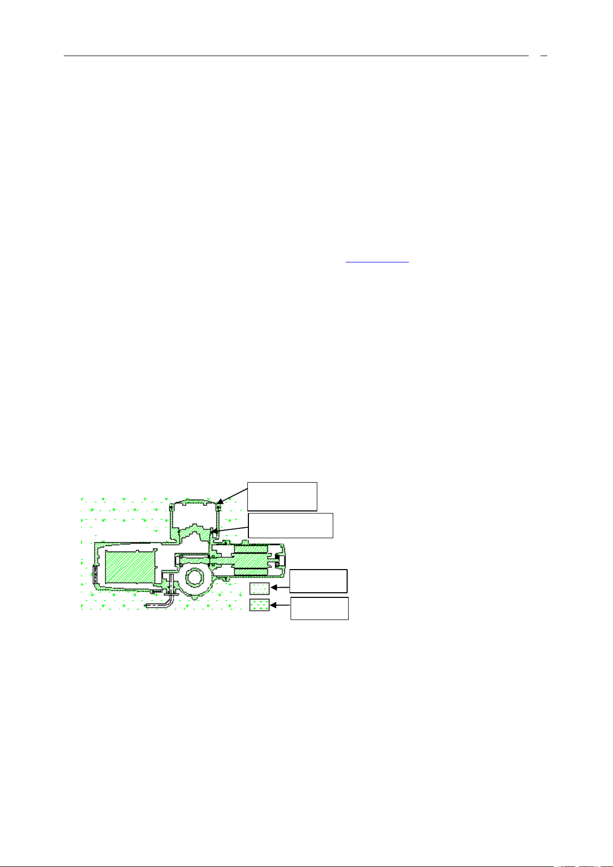
First sealed
Diagram 3-1
Humidity
Dust
Second sealed
installation and debugging instructions
Summarizing
1:1:1:
Summarizing
Summarizing
HKM actuator is the world leaderinthe field of electric al actuator products for the petroleum , gas, power,
water , waste treatment and so on industries. The series HKM actuator have two kinds of menu, one is the
Chinese menu, the other one is the English menu. Here we only explain the Chinese menu actuator, if you want
to know the English menu actuator, you can access our web-site: www.hurko.cn .
To
Hurko HKM actuator , we enjoy an unparalleled reputation for our imaginative and effective use of
advance technologies, and the quality and proven reliability of our products.
HKM actuator has the expertise to take on virtually any actuator challenge — including equipment for use
in
hazardous extreme cold and sub-sea conditions.
Customers choose HKM actuator for our ongoing commitment to:
Technological
Technological
Technological
through on-going research and development.
Flexibility:
Flexibility:
Flexibility:
to meet a vast range of specification quickly and efficiently.
Quality:
Quality:
Quality:
dispatch.
Reliability:
Reliability:
Reliability:
virtually maintenance free.
innovation:
innovation:
innovation:
every HKM actuator is precision-built using pre-manufactured modules of the finest materials
every HKM actuators are hanging assembled and fully rig tested to stringent standards prior to
every HKM actuators us e advanced lubrication, electrical, and sealing techniques, to be
at Hurko we pride ourselves on developing leading-edge actuation solution
Main
2:2:2:
Technique
Main
Main
Technique
Technique
■ Input signals:
4mA ~ 20mA;1VDC ~ 5VDC;
2mA ~ 10mA;0.5VDC ~ 2.5VDC;
20V ~ 60VDC
■ Power supply:
380VAC/50Hz;220VAC/50Hz
■ Accuracy: ≤ 1%
■ Deadband: 0.1 ~ 9.9% of travel between open and close limit positions
■ Enclosure: IP68
■ Anti explosion nark: Exd Ⅱ C T4
Parameters
Parameters
Parameters
or
30V ~ 220
VAC
electricity signal;
7
■ Ambient temperature: - 4 0 ℃ ~ +70 ℃
Switch close
No switch stem
Switch open
■ Ambient humidity: ≤ 95%
Features
3:3:3:
Features
Features
Specification
Specification
Specification
3.1The working principle of actuator
Motor spin to pass unite axle organization directly drive worm turn , worm drives worm gear to turn , and
then drives output shaft through clutch to turn. When switch handle turns ,inthe location of by hand , on clutch ,
move , take off open worm gear an d handwheel coupling, turn handwheel drive output shaft turn. Electric
operation is prior always, unless operating handle has been locked ,inthe files of by hand. When output shaft
turns , drives a pair of bevel gear to turn , and changes through valve position sensor detection valve position.
3 .2The function characteristic of actuator
3.2.1 Double sealed
All HKM actuator are double sealed watertight enclosure to IP68 (3 meters — 48hours) and provide
complete protection on the internal equipment even if the cable gland are opened. Refer to Diagram 3-1.
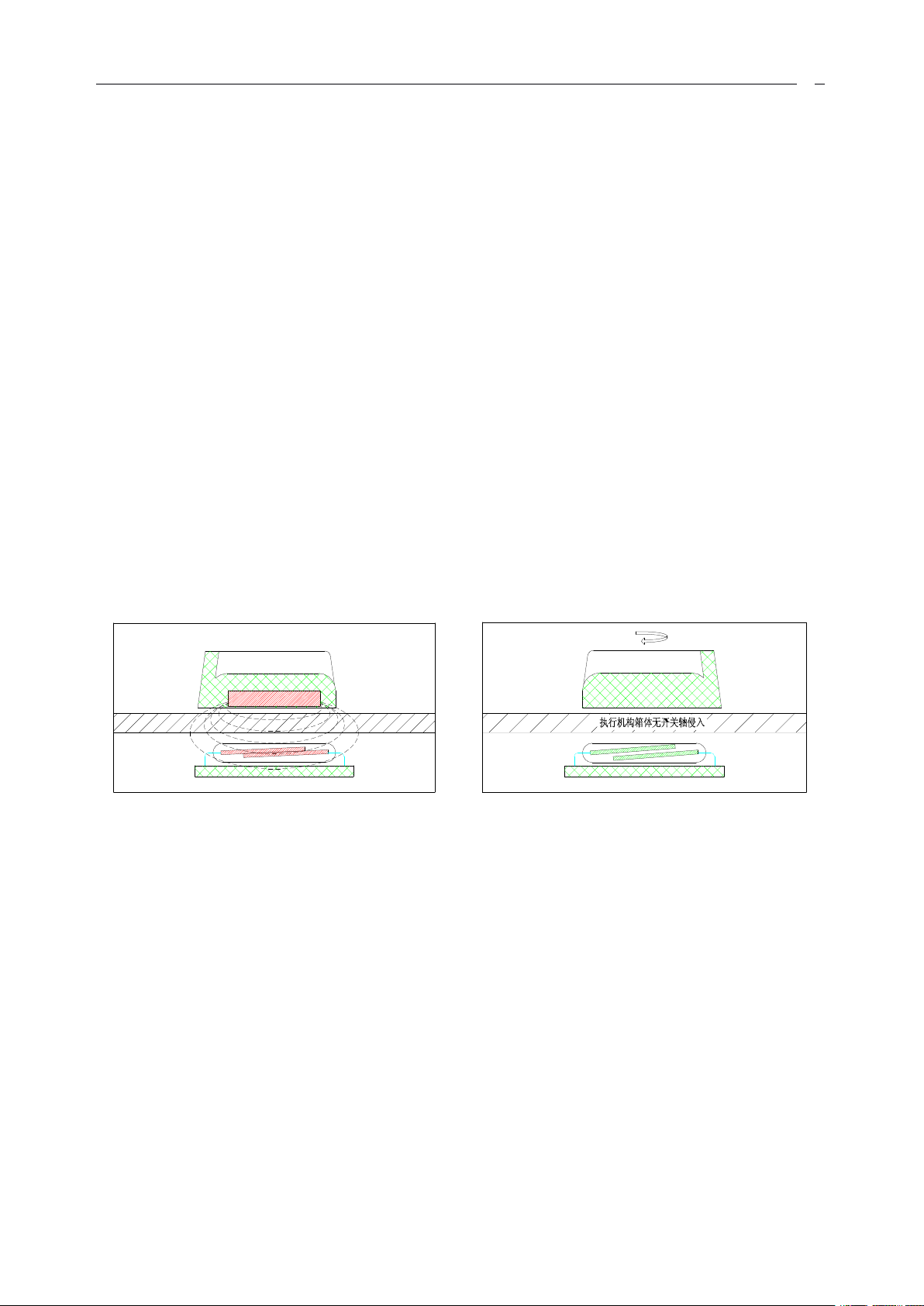
3.2. 2 Non-intrusive design
Non-intrusive switching:
The HKM electric actuator employs magnetic induction mode switching
Non-intrusive setting:
Can be instantly set, checked and actuator non-intrusively using the hand held infra-red setting tool.
Refer to Diagram 3-2 and Diagram 3-3.
Diagram 3 Non-intrusive designs
3.2. 3 Protection features
3.2. 3.1
The torque protection values are independently configurable
T
orque protection
in
the range 40 ~ 120% of rated torque ,serve
as over-torque protection for the entire valve travel.
3.2.3.2 Limit protection
When the actuator runs to close limit position or opening limit position, it will
stop(if limit position protect setting is “ 有 ” ).
3.2.3.3 Automatically phase order adjustment
HKM actuator automaticlydetect the phase order of the three-phase power supply , encourages the switch
of which one through proper logic operation when deciding actuator 's operation in order to guarantee the correct
phase order of the motor. If no this function the motor may be damage the valve because of the phase order
mistake of wiring. With this function the actuator need not consider the phase order.
3.2.3.4
It
is instant to turn on the contrary to protect
When actuator accepts to the order of opposite direction movement, adds a time voluntarily to postpone ,
prevents producing the unnecessary abrasion for valve shaft and gearbox..

8
3.2.3.5 Power supply losing- phase protection
HKM actuator has the losing- phase protect ion function.
current, can detect the power supply loses phase
not when the motor is
in
the operation course, so, can prohibit the motor start the operation, avoid to execute the
or
not, also can detect that if the power supply loses phase
It
adopts to watch on the voltage and the electric
running instruction to the motor when losing phase .
3.2.3.6 Protection when valve is locked
Regardless of actuator to open direction
or
close direction movement still, sending the signal that
encourages motor after second s time from 5 s to 1 0 s , temporarily, prohibit torque to be protected ( if the
actuator
in
the above-mentioned second time of 5-10 have no movement, control circuit can cut off the
power supply of motor ).
3.2.3.7 Motor over temperature protection
Two thermostats are embedded
in
the motor stator end windings that will trip and de-energise the motor if
the temperature exceeds its rating. The thermostats can be overridden during an ESD operation.
3.2.4 Checking for valve position and torque
The actuator has a pair of bevel gear to pick up the turn of the output shaft , drives a circular magnetic flat
on the circumference has many N poles and S poles, makes its two environmental magnetic quick switches
produce pulse signal,
let
the pulse signal be sentenced and counted so as to calculate the valve position.
Valve
position detection resolulion capacity is 11.5 ° output shaft corner, output shaft revolution amount to value
upper limit reaches 2040 turns , this stroke scope signifies HKM actuator is great.
The detection of torque comes to get from the detection of the electric current and magnetic flux, this has
realized the continuous measure for output torque, makes adjustment of the torque protection value can be
accomplish ed with the setting-tool easily.
3.2.5 Solid state relay and function of inertia braking
With solid state relay, substitute AC contactor has raised the working frequency of regulation type , and
has prolonged service life.
To
satisfy the requirement of higher positional accuracy, HKM actuator has offered inertia braking
function. If client needs when ordering goods the function of inertia braking, we offer the product that has this
function. Whether use this function can pa ss
by
user to setting tool, select
in
scene. The function of inertia
braking takes effect under various electric mode of operations.
What needs pay attention is that have used the function of inertia braking and have increased motor
winding give out heat to measure. Therefore we suggest the condition
in
necessity to use the function of inertia
braking.
or
3.2.6 Intermittent timing operation
Intermittent timing operation means that actuator will execute a period of time opening and execute a
period of time closing and a period of time opening again, and so on. The motion time and stopping time
may be setting
prevent hydraulic shock (water hamm er) and flow surge
by
the infra-red setting. This effectively increases the valve stroke time and can be adjusted to
in
pipelines.
3.2.7 Network communication
HKM actuator provided full compatibility with proprietary remote supervisory control system as well as
all current network communication protocols, including Modbus, Profibus and Foundation Fieldbus.
3.2.8 Actuator’s setting and check
All HKM actuator functions can be rapidly set and checked without removing the actuator covers (even
in
wet
or
hazardous conditions) using the free, infra-red setting tool supplied. Intrinsically safe-certified and
watertight, this handy device can al so be used to control the actuator locally.Actuator setting such as the
following functions with infra-red setting tool.

9
■ the rotary orientation of output shaft during the close stroke
█
Valve position
Alarm area
■ protection function of open limit position and close limit position
■ protection values for torque during the open
■ setting open
■ push to run
or
close limit position
or
maintain for local control
or
close stroke
■ setting ESD Optional function
■ setting analogue control signal
■ setting interlocks function
■ setting the four state indication relay
3.2.9 Display of the actuator
A
back-lit liquid crystal display gives digital indication from fully open to
fully close
in
1% increments. Two LED’s colored red, green for indication of
close and open. The liquid crystal could display menu, alarm and valve
position in the same panel. A nd the alarm includes valve alarm, actuator alarm,
control system alarm and actuator battery status. The back-lit will lighting as
long as main power was supplied. The local display can be rotated to suit
actuator orientation. Refer to Diagram 3-5. Diagram 3-5
3.2.10 Operation of the actuator
The mode of operation of actuator divides into the electric operation and hand operation. Actuator has
handwheel used
in
operating
by
hand. Hand / electric switch handle is used to get actuator switch to hand
operation, when the motor of actuator operates , switches organization because of having designed electric prior
operation, actuator can return to electric mode of operation voluntarily.
HKM actuator standard handwheel is top pack handwheel,atthe same time, we can offer the side that can
be chosen to pack handwheel, lean to pack handwheel turn
make
by
hand operating and more economic al.
by
deceleration gear biography go to output shaft,
3.2.11 S tructure of the actuator (see diagram 3-7)
a. Even if opening terminal coverinscene, the alone sealed terminal case can also guarantee the integrity of
the electric equipment.
b. The control switch and working way of field work encourage way with the magnetism of isolation, have
avoided needing sealed link up axle.
c. Show window on the spot can alternate different position,
in
order to meet the installation position of
actuator. Additionally pass seal up show window, the infrared ware of the use for special purpose is set and
diagnosed for actuator , need not open electrical case
in
scene and expose built-in control circuit , this can
prevente the control circuit from dust and moisture’s corrode.
d. Low inertia high torque motor. After starting , motor can reach the torque of peak value promptly, if the
motor has no excitation
accurate temperature switches , these can avoid efficiently that motor is
,it
will not nearly exceed restricted transport move ,
in
overheat state.
in
motor coil, there are some
e. The torque detection circuit of special design has avoided to use lever and the spring switch of torque
control.
f.
Worm
drives worm gearinoil bath, this can raise the actuator
g.
Valve
position counter can measure and control the stroke of actuator accurately, even if the power supply
shuts off and electrifys the power supply again , the actuator can also guarantee the enumerated accuracy of
’
s life farthestinthe different environment s.
valve position.
h. Directly drive handwheel but
in
power source appearance fault , offer reliable urgent hand operation.

10
i. The hand/ electric clutch can also be operated safely even if the motor is running.
Notice: When motor turns , clutch will automatically switch to electric mode, unless handle is locked in the
location of hand intentionally .
j. To raise life and be easy to dismantle , the thrust of design that can be lubricated , can unload actuator
under not change the condition of valve position.
k.
To
be convenient for suiting with valve , detachable drive bushing can be compound processing with
valve rod.
l.
To
change the output speed of actuator easily, motor axle and worm axle are mutually independent.
m. Support the bus line on-the-spot of open:Modbus, CAN, Profibus and FF etc.
3.2.12 The organization of explosion proof of actuator designs
The structural design of explosion proof of actuator is basis: GB3836.1-2000 《 Electrical equipment for
explosive gas atmosphere use the first part general requirement 》 and GB3836.1-2000 《 Electrical
equipment for explosive gas atmosphere use the second part separating explode type 》
in
which the relevant
stipulation and requirement are used to design the separating explode products, separating explode sign is
ExdIIBT4.
It
applys to 1 ,2 environments of work area that contain II A, II B level and the T1- T4 level
explosive mixture, atmosphere force 86 Kpa-106 Kpa, environmental temperature - 30 ℃ + 70 ℃ .
3.2.12.1 Good sealing
The combination surface of main housing and coordinate element is long
,
has little gap, this is advantageous
to the separating explode,atthe same time, with the fine O model sealing circle and the skeleton revolving oil
sealing of import,it is satisfied with the sealing requirement.
3.2.12.2 E quipment for inducting the cable into actuator
E quipment for inducting the cable is designed according to GB 3836.2 and appendix D 《 the supplementary
requirement that equipment for inducting the cable of separating explode type and gasket 》
explode structure, detail is shown
in
Fig.3 - 8. Thread combines length and sealing ring with the combination
,itis the separating
width of cable is suitable to the requirement of separating explode standard.
3.2.12.3 The inducting link of the explosive proof type actuator
Wire lead into structure have adopted outside thread coordination, the method and organization that fills with
fluid sealant have ensured the equipment of the separating explode performance, details are shown
in
Fig.3-9.
3.2.12.4 The window structure of the explosion proof type actuator
Transparent window and housing have joined with O model weather strip and fluid sealant fill ( this place
must not open,otherwise can destroy to separating explode surface), double-deck transparent material presses
to surround the structural installat ion that compressed tightly,have satisfied the requirement of 5.4, 5.5 and 8.1
in
GB 3836.2, detail is shown
To
guarantee that the installation of actuator
in
Fig.3 - 10.
in
difference has normal liquid crystal on direction to show
direction, character shows normally that the liquid crystal of direction and actuator shows that screen has offered
4 kinds installation:
a. Actuator horizontal direction installation ( handwheel upturns
),
liquid crystal shows that screen is installed
according to normal location;
b. Under actuator dynasty lean direction installation ( handwheel adown), liquid crystal shows that screen is
installed according to normal location, can use setting tool to make the show way as show on the contrary;
c. The actuator direction of left side installation ( handwheel leftward
),
liquid crystal shows that screen is
installed near flange a side;
d. The actuator direction of right side installation ( handwheel rightward
),
liquid crystal shows that screen is
installed near flange a side, can use setting tool to make the show way as show on the contrary;
The installation direction that offers actuator more
by
user, we show the correctly installation supply of screen
according to liquid crystal. If user does not offer the installation of actuator direction easily, we can send the

11
staff to the spot to set the direction of the liquid crystal screen.
Actuator rpm
182436487296144
192
HKM
HKM
HKM
0 3
HKE03
Modulation torque N.m
171715.6
13.6
Max torque N . m
444439
35
Motor power kW
0.07
0.07
0.13
0.14
Rated currentAA
0.75
0.7511.1
Modulation thrust KN
7.14
7.14
6.55
5.71
Max thrust KN
14.2
14.2
12.6
8.4
Liner speed mm/s
1.5234HKM 0 5
HKE05
Modulation torque N.m
343430
27
Max torque N . m
807070
63
Motor power kW
0.12
0.13
0.19
0.23
Rated currentAA
0.8510.5
2.1
Modulation thrust KN
14.2
14.2
12.6
8.4
Max thrust KN
25.6
22.6
22.6
20.1
Liner speed mm/s
1.523
4
HKM10
HKE10
Modulation torque N.m
8181685447
Max torque N . m
159
142
1068971
Motor power kW
0.3
0.3
0.35
0.35
0.47
Rated currentAA
2.3
2.3
2.8
2.8
3.6
Liner speed mm/s
1.8
2.4
3.6
4.8
7.2
HKM 20
HKE20
Modulation torque N.m
152
152
129
102
102
Max torque N . m
266
266
212
177
177
Motor power kW
0.47
0.47
0.58
0.68
0.7
Rated currentAA
3.6
3.6
4.6
5.5
5.5
Modulation thrust KN
252521
16.7
14.5
Max thrust KN
33.7
33.72521
16.7
Liner speed mm/s
1.8
2.4
3.6
4.8
7.2
3.2.13 Electronic latch function
Actuator has arisen the phenomenon of over torque very easily when starting high inertia load.
start high inertia load successfully, HKM actuator prohibits torque temporarily
in
sending some seconds of
To
be able to
times after signal that encourage motor to protect function. This is electronic latch function. If have sent the
signal that encourages motor for some seconds actuator can not move, control circuit can break the power source
of motor. Electronic latch function for open the valve that is
in
clo sed position for a long time very effective.
3.2.14 P rotect data function when main power source falls
When main power source loses electricity, from battery, supplies power to valve position detection circuit,
and preserve valve position
in
EEPROM. Battery still supplies power to LCD ( but do not sustain to be shaded )
and supplies power to 4 state ins truction relaies, the service life of battery can reach 2 years. Suggest to change
battery when main power source has electricity.
3.2.15 Application range
HK M actuators are suitable for proportional control
in
automatic control loops
that the system rate of change is relatively high, and high accuracy continuous modulation
is necessary. When modulating applications require increased rates of starts per hour, the HKM actuator ranges
can be operated up to a rate of 1200 starts per hour providing the average torque required
by
the valve in mid
stroke does not exceed 50% of the rated torque of the selected actuator.
HKM actuator with W gear units could drive quarter turn modulating valve. And this combination output
rated torque from 470 to 51500 N • M. For more detail information about gearbox please send message to our
company.
4:4:4:
Actuator
Actuator
Actuator
Data
Data
Data
T he Table 4-1, Table 4-2,Table 4-3,Table4-4 and Table4-5 is also suitable for the HKE series actuator.
Table
Table
Table
444
–––
111
PPP
arameters of the multi-turn actuator ( 380V AC/50Hz
380V AC/50Hz
380V AC/50Hz
)

12
Table
HK M5 5
HKE55
Modulation torque N.m
27
271
253
203
203
Max torque N . m
708
708
531
407
284
Motor power kW
0.9
1.05
1.27
1.2
1.35
Rated currentAA
679
7.8
8.2
Modulation thrust KN
27
271
253
203
203
Max thrust KN
708
708
531
407
284
Liner speed mm/s
2.4
3.2
4.8
6.4
9.6
Actuator rpm
182436487296144
192
HKHKHK
M 0 3
HKE03
Modulation torque N.m
121210
10
Max torque N . m
242421
20
Motor power kW
0.06
0.08
0.08
0.1
Rated currentAA
1.6
1.8
1.8
1.9
Modulation thrust KN
554.4
4.1
Max thrust KN
7.1
7.1
6.6
5.7
Liner speed mm/s
1.523
4
HK M0 5
HKE05
Modulation torque N.m
201815
13
Max torque N . m
423833
27
Motor power kW
0.12
0.12
0.12
0.12
Rated currentAA
2222Modulation thrust KN
8.4
7.6
6.3
5.5
Max thrust KN
12.6
11.3
9.7
8
Liner speed mm/s
1.523
4
HKM10
HKE10
Modulation torque N.m
4032262518
Max torque N . m
8577585538
Motor power kW
0.19
0.21
0.23
0.25
0.28
Rated currentAA
2.3
2.45
2.8
3.2
3.4
Modulation thrust KN
12.4
9.9
8.1
7.8
5.6
Max thrust KN
18.9
17.1
12.7
12.1
8.4
Liner speed mm/s
1.8
2.4
3.6
4.8
7.2
Actuator rpm
182436487296144
192
HKM
HKM
HKM20HKE20
Modulation torque N.m
7070554242
Max torque N . m
133
133
1078989
Motor power kW
0.28
0.35
0.32
0.35
0.37
Rated currentAA
3.4
3.75
3.6
3.75
3.9
Modulation thrust KN
21.7
21.7
17.11313
Max thrust KN
31.6
31.6
25.4
21.1
21.1
Liner speed mm/s
1.8
2.4
3.6
4.8
7.2
HKM55
HKE55
Modulation torque N.m
180
150
130
102
72
Max torque N . m
343
328
265
204
142
Motor power kW
0.8
0.8
0.75
0.8
0.8
Rated currentAA
2.4
3.2
4.8
6.4
9.6
Modulation thrust KN
57.64841.6
32.6
23
Max thrust KN
878165
50.2
34.9
Liner speed mm/s
57.64841.6
32.6
23
Actuator type
HK M 03 / HKM 0 5
HKM10 / HKM20
HKM55
Type A
Rated thrust KN44100
150
Max bore
Outside bore mm3251
67
Inside bore mm2638
57
Table
Table
444
---
222
PPP
arameters of the multi-turn actuator ( 220V AC/50Hz
220V AC/50Hz
220V AC/50Hz
)
Table
Table
Table
Table
Table
Table
444
---
222
PPP
arameters of the multi-turn actuator ( 220V AC/50Hz
4-3
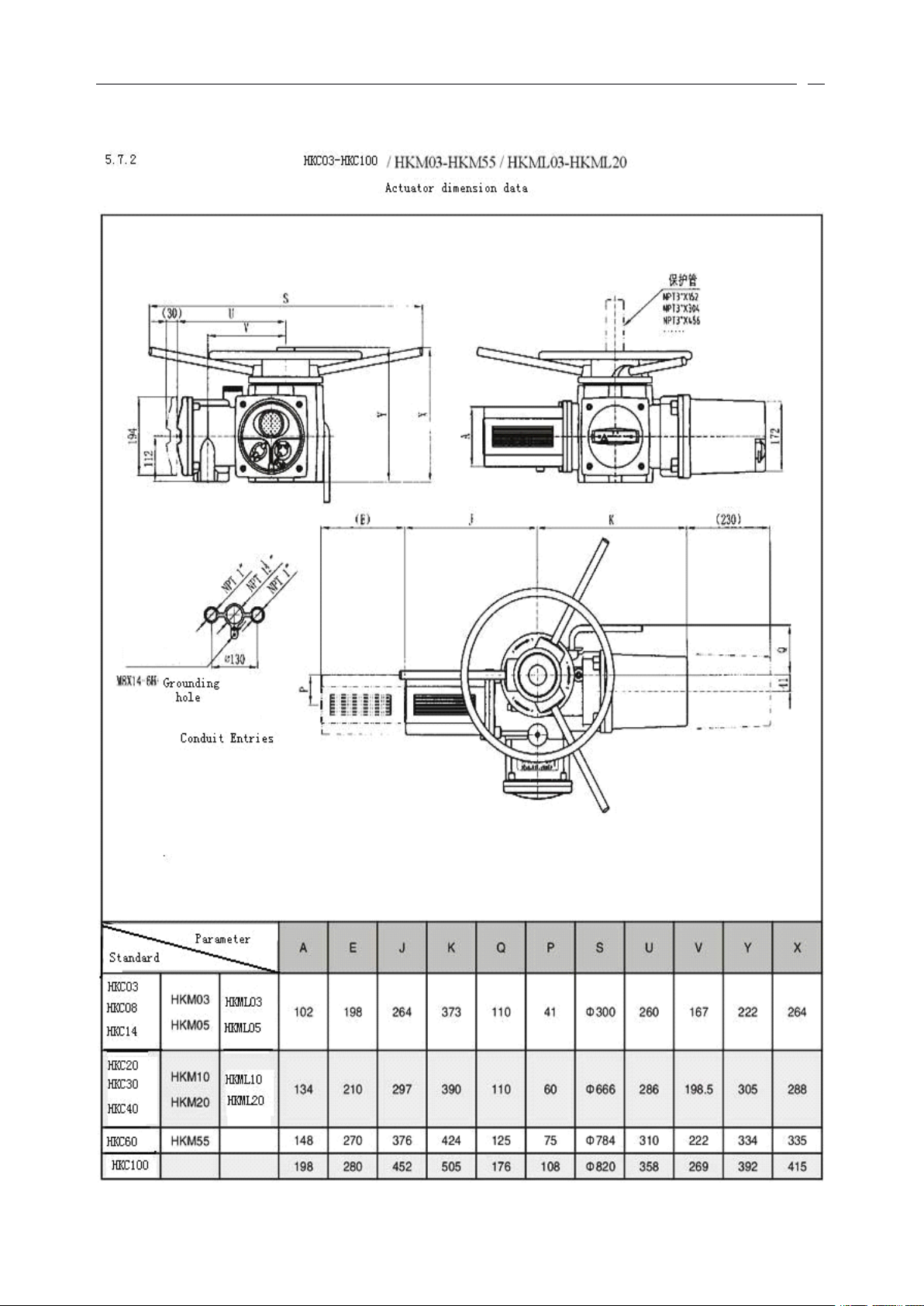
dimension
4-3
4-3
dimension
dimension
table
table
table
the
interface
ofofof
the
the
interface
interface
220V AC/50Hz
220V AC/50Hz
continu
)
(((
continu
continu
eee
)))

13
Table
Type B
B1 mm4260
80
B3 mm2030
40
B4 mm2030
44
Hand-wheel gearbox ratio
Standard
Directly
Directly
Directly
Extra option——
—
Flange size
F10
F14
F16
Net weight3355
80
Type
Output rev rpm
1824364872
HKML03
HKEL03
The diameter of drive screw rod
26/3
---
Max.liner stroke mm
115
---
Flange type(ISO 5210)
F10
---
Regulate thrust KN
9.20
9.20
8.45
7.37
Liner speed mm/sec
0.9
1.2
1.8
2.4
Rated close thrust KN
18.43
18.43
16.26
14.63
HKML05
HKEL05
The diameter of drive screw rod
26/3
Max.liner stroke mm
115
Flange type(ISO 5210)
F10
Regulate thrust KN
18.43
18.43
16.26
14.63
Liner speed mm/sec
0.9
1.2
1.8
2.4
Rated close thrust KN
33.06
29.27
29.27
26.02
HKML10
HKEL10
The diameter of drive screw rod
32/6
Max.liner stroke mm
115
Flange type(ISO 5210)
F14
Regulate thrust KN
31.15
31.15
26.12
20.74
18.06
Liner speed mm/sec
1.8
2.4
3.6
4.8
7.2
Rated close thrust KN
46.87
41.87
31.15
26.12
20.74
HKML10
HKEL10
The diameter of drive screw rod
38/14
Max.liner stroke mm
115
Flange type(ISO 5210)
F14
Regulate thrust KN
18.91
18.91
15.88
12.61
10.97
Liner speed mm/sec
4.2
5.6
8.4
11.2
16.8
Rated close thrust KN
28.49
25.45
18.91
15.88
12.61
HKML20
HKEL20
The diameter of drive screw rod
32/6
Max.liner stroke mm
115
Flange type(ISO 5210)
F14
Regulate thrust KN
58.39
58.39
49.56
39.18
39.18
Liner speed mm/sec
1.8
2.4
3.6
4.8
7.2
Rated close thrust KN
78.37
78.37
62.62
52.25
52.25
HKML20
HKEL20
The diameter of drive screw rod
38/14
Max.liner stroke mm
115
Flange type(ISO 5210)
F14
Regulate thrust KN
35.49
35.49
30.12
23.82
23.82
Liner speed mm/sec
4.2
5.6
8.4
11.2
16.8
Rated close thrust KN
47.64
47.64
38.06
31.76
31.76
Type
Output rev rpm
1824364872
HKML03
The diameter of drive screw rod
26/3
Table
Table
4-4
4-4
4-4
P arameters of the linear-travel actuator(380VAC/50Hz)
Table4-5
Table4-5
Table4-5
arameters
PPP
arameters
arameters
ofofof
the
liner
liner
liner
-travel
-travel
-travel
the
the
actuator(220V AC/50Hz)
actuator(220V AC/50Hz)
actuator(220V AC/50Hz)

14
ctuator
HKEL03
Max.liner stroke mm
115
Flange type(ISO 5210)
F10
Regulate thrust KN
6.50
6.50
5.42
5.42
Liner speed mm/sec
0.9
1.2
1.8
2.4
Rated close thrust KN
13.00
13.00
11.38
10.84
HKML05
HKEL05
The diameter of drive screw rod
26/3
Max.liner stroke mm
115
Flange type(ISO 5210)
F10
Regulate thrust KN
10.84
9.76
8.13
7.05
Liner speed mm/sec
0.9
1.2
1.8
2.4
Rated close thrust KN
22.76
20.60
17.89
14.63
HKML10
HKEL10
The diameter of drive screw rod
32/6
Max.liner stroke mm
115
Flange type(ISO 5210)
F14
Regulate thrust KN
15.37
12.29
9.99
9.60
6.91
Liner speed mm/sec
1.8
2.4
3.6
4.8
7.2
Rated close thrust KN
32.65
29.58
22.28
21.19
14.60
HKML10
HKEL10
The diameter of drive screw rod
38/14
Max.liner stroke mm
115
Flange type(ISO 5210)
F14
Regulate thrust KN
9.34
7.47
6.07
5.84
4.20
Liner speed mm/sec
4.2
5.6
8.4
11.2
16.8
Rated close thrust KN
19.85
17.98
13.54
12.84
8.87
HKML20
HKEL20
The diameter of drive screw rod
32/6
Max.liner stroke mm
115
Flange type(ISO 5210)
F14
Regulate thrust KN
26.89
26.89
21.13
16.13
16.13
Liner speed mm/sec
1.8
2.4
3.6
4.8
7.2
Rated close thrust KN
51.09
51.09
41.10
34.19
34.19
HKML20
HKEL20
The diameter of drive screw rod
38/14
Max.liner stroke mm
115
Flange type(ISO 5210)
F14
Regulate thrust KN
16.35
16.35
12.84
9.81
9.81
Liner speed mm/sec
4.2
5.6
8.4
11.2
16.8
Rated close thrust KN
31.06
31.06
24.99
20.78
20.78
555
:::
AAA
ctuator
ctuator
5.1 Torque and turning range
■ position setting range: 3.5 to 2040 turns, with a minimum angular resolution to 11.5 ° of actuator output
center column.
■ torque switch setting: 40% to 120% rated torque.
5.2 Cable entry and connecting terminals
The sizes of three cable entries are double M25 and M40.make cable entries appropriate to the cable type
and size. The sizes of four power terminals are M5. The sizes of control terminals are M4. Check that supply
voltage is the same as that, marked on th e actuator nameplate begin
5.3 Interface for machine installation
The actuator contains thrust type and non-thrust type. The thrust type is:A type, the non-thrust type is made
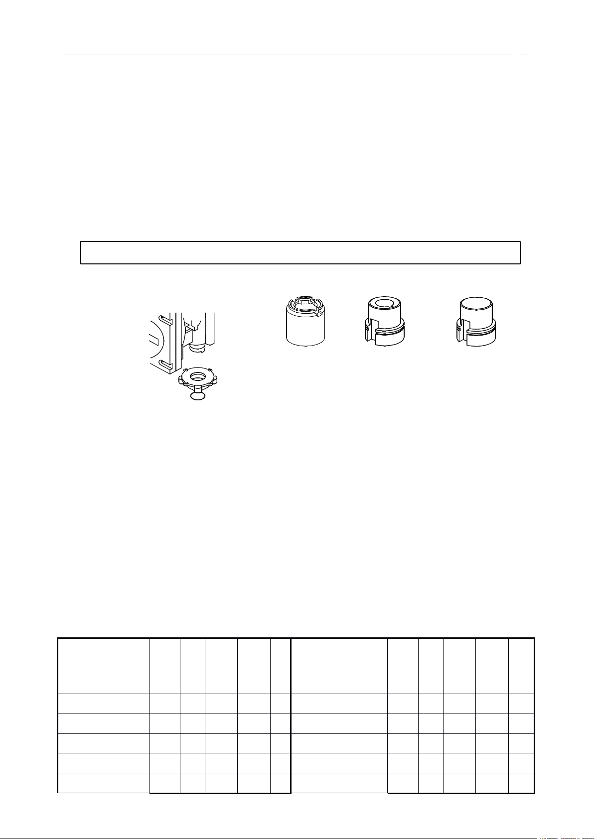
of B1,B3,B4. The drive bush’s shape for every link types please refer to diagram 5-1 and diagram 5-2.
5.3.1 Type
The type
5.3.2 Type B drive bush
erformance
PPP
erformance
erformance
A
drive bush
A
thrust bush suit the position of the valve-mounting flange.
by
connecting these cables.
15
Driving shaft bored and keyed to ISO 5210 standard. And the type B non-thrust bush has three basic form
Combination
Rated
Torque
(N.m)
Stroke
Time
(s)
Actuator
RPM
(rpm)
Gearbox
Ratio
Max
Bore
(mm)
Combination
Rated
Torque
(N.m)
Stroke
Time
(s)
Actuator
RPM
(rpm)
Gearbox
Ratio
Max
Bore
(mm)
HK M03B4/ W4
4102936
70 :164HK M1 0 B4/ W6
1 7 702936
70 :1
102
HK M03B4/ W4
2802524
40 :164HK M1 0 B4/ W6
2 0524424
70 :1
102
HK M03B4/ W4
2673318
40 :164HK M20B4/ W6
27342248
70 :1
102
HK M03B4/ W4
4184424
70 :164HK M1 0 B4/ W6R
25372972
140 :1102
HK M0 5 B4/ W4
5582524
40 :164HK M1 0 B4/ W6R
27504448
140 :1102
Diagram 5-1: Links of basic-base drive-bush for HKM03~HKM55 actuator
Type
Type
Type
B1B1B1
Used in
HKM03 ~ HKM55
Type
Type
Type
B4B4B4
Used
in
HKM03~HKM55
Type
Type
Type
B3B3B3
Used
in
HKM03~HKM55
Diagram 5-2: Links of non-thrust type drive-bush for type HKM03~HKM55
as follows B1, B3 and B4.
5.3.3 Type B1
The B1 is supplied a big key and shaft to drive the valve.
5.3.4 Type B3
The B3 is supplied a small key and shaft to drive the valve.
5.3.5 Type B4
B4 is supplied blank and must be machined to suit the input shaft of the gearbox
thatitwill drive.
a. Thrust type:
b. Non-thrust type:
or
valve
5.4 Additional gear-box
You
can use the gear-box to make the HKM linear stroke actuator as the angular stroke actuator, please see
table 5-2.
5.5 O scillation
The normal oscillation frequency and intensity for rang HKM is during the 10Hz ~ 200Hz and 0.5 times
acceleration of gravity .
5.6 Shielding and flameproof
Waterproof type: accord with <<GB4208-84>> IP68 proof grade
Flameproof type: accord with <<GB3836.1.2-2000>> d Ⅱ BT4 proof grade
Table 5-2 HK M actuator /W gearbox combination data

16
5.7
HK M0 5 B4/ W4
7232248
70 :164HK M1 0 B4/ W7
20163824
60 :1
127
HK M0 5 B4/ W4
5353318
40 :164HK M20B4/ W7
33282536
60 :1
127
HK M0 5 B4/ W4
7892936
70 :164HKM20B4/ W7
37843824
60 :1
127
HK M03B4/ W4R
4472548
80 :164HK M1 0 B4/ W7R
26903848
120 :
1
127
HK M03B4/ W4R
5033336
80 :164HK M1 0 B4/ W7R
36403872
180 :
1
127
HK M0 5 B4/ W5
4382524
40 :176HK M20B4/ W8
38003824
60 :1
153
HK M0 5 B4/ W5
8422248
70 :176HK M5 5 B4/ W8
63702536
60 :1
153
HKM 0 5 B4/ W5
4173318
40 :176HK M5 5 B4/ W8
68303824
60 :1
153
HK M0 5 B4/ W5
9152936
70 :176HK M20B4/ W8R
48803848
120 :1153
HK M0 5 B4/ W5
10144424
70 :176HKM20B4/ W8R
7 32 53872
180 :1153
HK M03B4/ W5R
5253848
120 :176HKM20B4/ W8R
60723836
60:1
153
HK M0 5 B4/ W5R
69525488076
HK M5 5 B4/ W9
62112524
60 :1
178
HK M0 5 B4/ W5R
76033368076
HK M5 5 B4/ W9
154123872
180:
1
178
HK M0 5 B4/ W5R
16184448
14076HK M5 5 B4/ W9R
170043824
60:1
203 .
2
HK M0 5 B4/ W6R
16184448
140
102
HK M5 5 B4/ W10
171483872
180:1203 .
2
Coupling
5.7
5.7
Coupling
Coupling
5.7.1
5.7.1
5.7.1
Coupling
Coupling
Coupling
interface
interface
interface
interface
interface
interface
for
HKM/HKML
for
for
HKM/HKML
HKM/HKML
17
you
***
change
IfIfIf
you
you
change
change
the
string
string
string
"HKM"
"HKM"
"HKM"
the
the
into
into
into
"HKE",
"HKE",
"HKE",
the
above
the
the
data
above
above
data
data
also
suitable
isisis
also
also
suitable
suitable
for
the
HKE
for
for
the
the
HKE
HKE
range.
range.
range.

18
you
***
change
IfIfIf
you
you
change
change
the
string
string
string
"HKM"
"HKM"
"HKM"
the
the
into
into
into
"HKE",
"HKE",
"HKE",
the
above
the
the
data
above
above
data
data
also
suitable
isisis
also
also
suitable
suitable
for
the
HKE
for
for
the
the
HKE
HKE
range.
range.
range.
19
you
***
change
IfIfIf
you
you
change
change
the
string
string
string
"HKM"
"HKM"
"HKM"
the
the
into
into
into
"HKE",
"HKE",
"HKE",
the
above
the
the
data
above
above
data
data
also
suitable
isisis
also
also
suitable
suitable
for
the
HKE
for
for
the
the
HKE
HKE
range.
range.
range.
20
you
***
change
IfIfIf
you
you
change
change
the
string
string
string
"HKM"
"HKM"
"HKM"
the
the
into
into
into
"HKE",
"HKE",
"HKE",
the
above
the
the
data
above
above
data
data
also
suitable
isisis
also
also
suitable
suitable
for
the
HKE
for
for
the
the
HKE
HKE
range.
range.
range.
21
Stop
Close
Close
Open
Open
:Actuator
Diagram 6-1
Control
Actuator
5
353336
4
Close
Open
23
22
Valve
position feedback 4 ~ 20mA
Diagram 6-1 push to run open/close control
Control
Actuator
Control
Actuator
345333436
4355
33354
36
666
:Actuator
:Actuator
The wiring code card fixed
Control
Control
Control
and
wiring
and
and
wiring
wiring
(this
section
(this
(this
section
section
in
the terminal cover is particular to each
isisis
suitable
suitable
suitable
for
HKC
for
for
HKC
HKC
range)
range)
range)
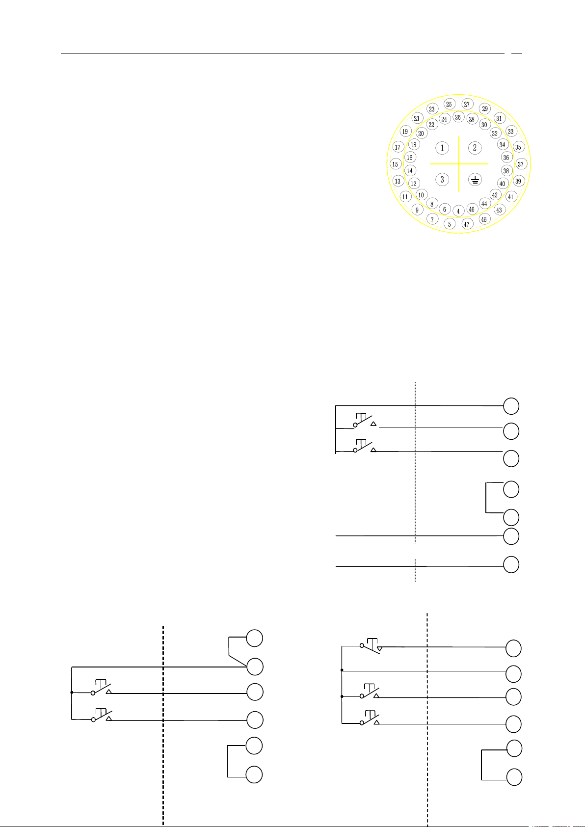
actuator. The HKM actuator wiring code, please refer to diagram 7. The
means of each terminal refer to the diagram 6-1.
6.1 Local controls
Non-intrusive selectors are provided on the actuator electrical control
cover, one for local/stop/remote selection, pad-lockable
in
each position,
and the other open/close control. Local control may be configured for
maintained
or
push to run operation.
6.2 Remote manual controls
The power supply of remote control circuits can be provided as DC 24V
actuator internal supply
or
DC/AC 24V ~ 60V,AC 120 ~ 220V by external supply.
Refer to the circuit diagram 6-1 to 6-3.
by

22
Table 6-1 terminals description
NO
NAME
OPERATION
Connect with crust
Connect with grounding
1
Power supply terminal
380VAC(or 220VAC) input terminal
2
Power supply terminal
380VAC(or 220VAC) input terminal
3
Power supply terminal
380VAC(or void) input terminal
4
DC 0V
DC 24V “ - ” output
5
DC 24V
DC 24V “ + ” output
6
S1 relay terminal 1
Indication S1 relay terminal 1
7
S1 relay terminal 2
Indication S1 relay terminal 2
8
S 2 relay terminal 1
Indication S 2 relay terminal 1
9
S 2 relay terminal 2
Indication S 2 relay terminal 2
10
S 3 relay terminal 1
Indication S 3 relay terminal 1
11
S 3 relay terminal 1
Indication S 3 relay terminal 2
12
S 4 relay terminal 1
Indication S 4 relay terminal 1
13
S 4 relay terminal 2
Indication S 4 relay terminal 2
14
Battery relay terminal 1
Indicate battery power is too low ,the relay contact 1
15
Battery relay terminal2
Indicate battery power is too low , the relay contact 2
16
Temperature relay terminal 1
Indicate motor temperature is high, the relay contact 1
17
Temperature relay terminal 2
Indicate motor temperature is high , the relay contact 2
1819Remote relay terminal 1
Remote position indication relay , common terminal
20
Remote relay terminal 2
Remote position indication relay , normally close terminal
21
Remote relay terminal 3
Remote position indication relay , normally open terminal
22
Valve
position feedback signal +
Valve
position current analogue signal feedback terminal +
23
feedback signal common terminal
Valve
position current analogue signal feedback terminal +
24
Torque feedback signal +
Torque current analogue signal feedback terminal l
25
ESD
Emergent (ESD) active signal input terminal
26
Valve
position input signal +
Valve
position current analogue signal input terminal +
27
Valve
position input signal -
Valve
position current analogue signal input terminal -
2829Open position relay terminal 1
Valve
position fully open indication relay terminal 1
30
Open position relay terminal 2
Valve
position fully open indication relay terminal 2
31
Interlock low voltage terminal
Interlock low voltage common-terminal
32
Interlock high voltage terminal
Interlock high voltage common-terminal
33
Remote close
Remote close input terminal
34
Stop/maintain
Stop/maintain input terminal
35
Remote open
Remote open input terminal
36
Remote low voltage terminal
ESD, remote open/close, stop/maintain low voltage common-terminal
37
Open interlock
Open interlock input terminal
38
Close interlock
Close interlock input terminal
39
Manual/automatic terminal
Manual/automatic signal input terminal
40
Remote high voltage terminal
ESD, remote open/close, stop/maintain high voltage common-terminal
23
22
23
22
Valve
position feedback 4 ~ 20mA
Valve
position feedback 4 ~ 20mA
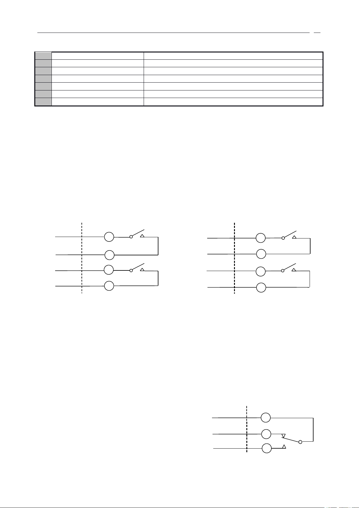
Diagram 6-2 maintain open/close control, support
reversion, intermediate position impossible
Diagram 6-3 maintain open/close/stop control
23
6.3 State indication relay
41
Manual/auto low voltage terminal
Manual/automatic low voltage common-terminal
42
Monitor relay terminal 1
Monitor relay common terminal
43
Monitor relay terminal 2
Monitor relay normally close terminal
44
Monitor relay terminal 3
Monitor relay normally open terminal
45
Manual/auto high voltage terminal
Manual/automatic high voltage input terminal
46
Close position relay terminal 1
Valve
position fully close indication relay terminal 1
47
Close position relay terminal 2
Valve
position fully close indication relay terminal 2
Actuator
Control
S1
6
7
S2
8
9
S3
10
11S412
13
Actuator
Control
Normally open
Normally open
Normally open
Normally open
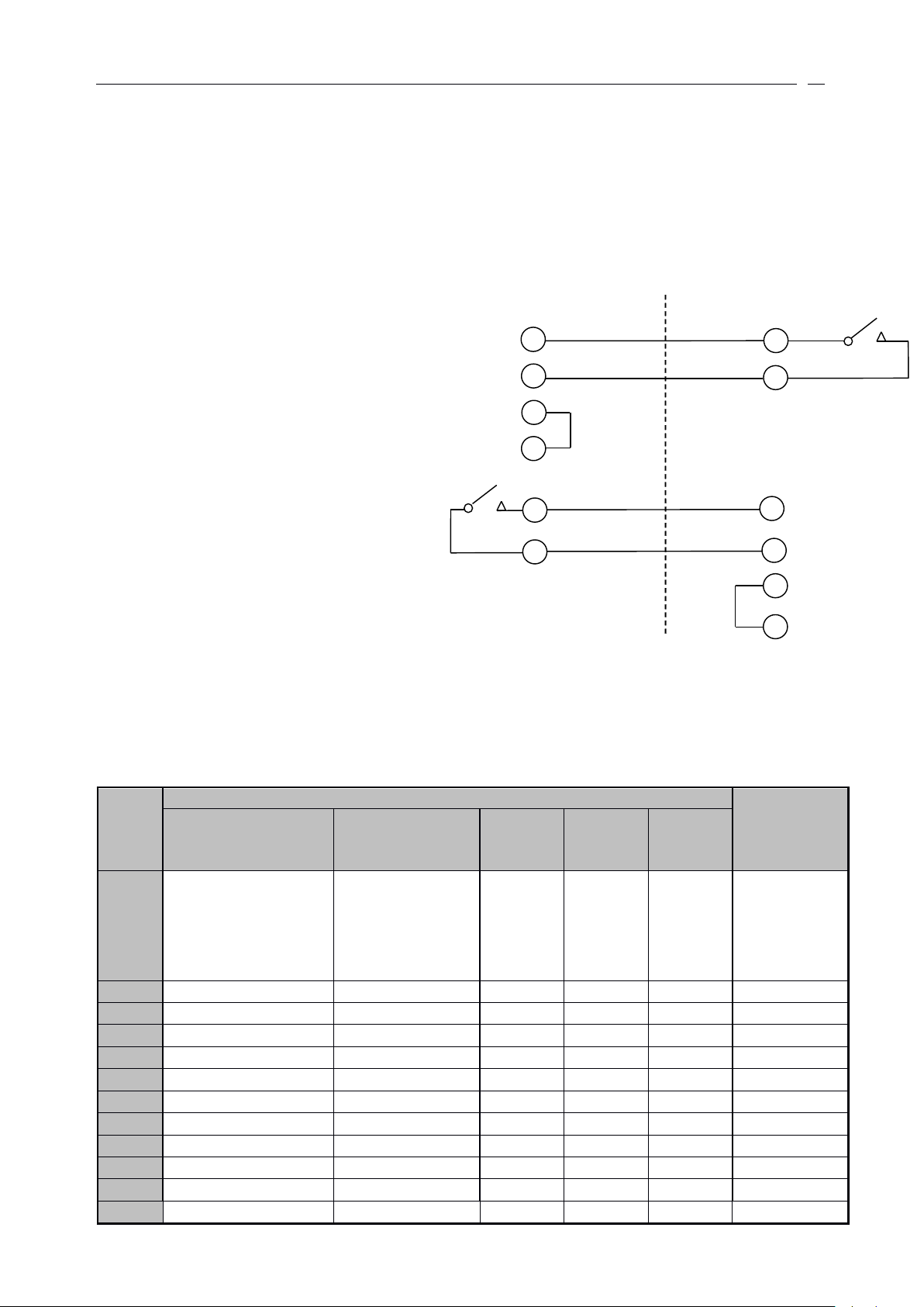
Diagram 6-10 state indication relays
Diagram 6-11 monitor relay
wiring diagram
Actuator
Control
44
42
43
Normally close
Four state indication relay are provided, each one independently configurable using the HKM setting tool
to signal one of the following:
■ valve position
Fully open, fully close
or
any intermediate positions
■ status
Valve opening, closing, moving
valve alarms
■
Motor tripped on torque going open, going close, valve jammed
■ actuators alarms
Battery low
Each contact can be configured to either “ normally open ”
5A/250VAC
or
5A/30VAC.
Refer to diagram 6-5.
6.4 Monitor relay
An independent relay with a volt-free changeover contact
used for monitoring actuator electrical availability. Contact
rating 5A/250VAC
or
The relay will de-energise under a one,orcombination, of
the following conditions:
■ loss of one
or
more of the power supply phases
■ main control circuit is error
■ motor thermostat tripped
5A/30VAC.
or
“ normally close ” . Contacts are rated
at
24
■ mode switch is not
Item
Extra functions
Wiring
diagram
number
111
222
333
444
555
Base
Circuit
Battery low,
remote control select
and
thermostat tripped
alarm relay
Valve
position fully
open and
valve position fully
close
indication relay
Analogue
signal
input
Valve
position
signal
feedback
Torque
signal
output
√
—————
1 00-00√√
—
1 01-
√
—
√
1 02-
√
√
√
1 03- √
√
—
—
1 -01
√
—√—
1 -02
√
√√—
1 -03√
—
—
√
1 -04
√
√—√
1 -05
√
—√√
1 -06
√
√
√
√
1 -07
Diagram 6-12 interlock
3 853 7
3 148
9
453 176
24V DC +
24V DC +
24V DC -
24V DC
Contact close when valve fully close
Auxiliary actuator
Main actuator
Contact close when valve fully open
Close interlock
at
the remote position
Refer to diagram 6-11.
6.5 Emergency shut down - ESD
An active ESD signal will override any local
separate common to that used for open, close.
The following ESD options can be configured:
■ ESD signal
Active high, active low
■ ESD action
Close, open
■ ESD override
Motor thermostat
6.6 Interlocks
External hardwired interlocks for
opening, closing
or
both directions can be
configured to inhibit local and remote
operation until the external contacts are made.
Interlock circuits may be added with any of the
remote control circuits. The interlock inpu ts
operate from a separate common allowing for
isolation between the safety system and
operation control system.
Refer to Diagram 6-12.
or
remote control signal. The ESD input operates from a
6.7 HKM /HKC actuator extra functions option
Refer to Table 6-2.
Table 6-2 HKM /HKC actuator addition circuit and wiring diagram number

25
NOTE: “—” means you do not select ; “ √” means you already select ; “×” means you can select 。
6 × 10
4
32N
ms
> Pulse length >
18 × 10
4
32N
Example:If you selected 1,3,4 functions, the wiring diagram number is 101-03 。
6.7.1 Alarm relay
The extra alarm relay option provides five additional changeover relays. The extra alarm relay functions
are show below:
■ valve position fully open
■ valve position fully close
■ battery low
■ remote control select
■ thermostat tripped
6.7.2 Analogue signal input/output Module
The analogue signal input/output board provides a non-contacting internally fed 4 ~ 20mA analogue
signal prointerfaceional to valve position. Available
that may be connected to the signal is 500 ohms
at
terminals 22 and 23, the maximum external impedance
at
nominal supply voltage.
Analogue signal input impedance:
4mA ~ 20mA/250 ohm;1VDC ~ 5VDC/1M ohm;2mA ~ 10mA/250 ohm;0.5VDC ~ 2.5VDC/1M ohm
6.8 Analogue signal control
The HKM actuator analogue signal prointerfaceional controllers enable the actuator to automatically
position a valve
in
prointerfaceion to an analogue current
or
voltage.Asignal derived from the actuator noncontacting position sensor is electronicallycompared with a signal prointerfaceional to the input signal. The
difference between them triggers the open
position is therefore automatically adjusted
operation can be prevented
by
the adjustable deadband and the Motion inhibits Timer features.
or
close contactor
in
prointerfaceion to analogu e signal. Unnecessary frequent
in
the direction that will cancel the error.
■ Position corresponding to low input signal: close limitorpercentage open
■ Position corresponding to high input signal: open limitorpercentage open
■ deadband: 0.1 ~ 9.9% of travel between open and closed limit positions
■ motion inhibit time: 0.1 ~ 9.9 sec between actuator movements
■ action on loss of input signal: stay-put, move to high
or
low signal position. Response on loss of signal
will occur if signal falls below 50% of set “ low ” signal.
6.9 Pulse control
In the omputercontrol system, the user may be used the pulse control the actuator. HKM actuator are
fitted this control mode.
Please refer to diagram 6-14
Valve
■ the interval of pulse must according to maximum 1200 starts per hour and 50% working time.
■ Pulse width according to the output rpm N
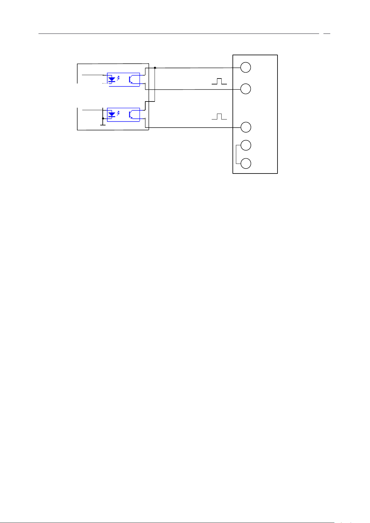
26
Actuator
53543633
#1 output (close control)
Control system
output module
#2 output (open control)
Diagram 6-14 pulses control sketch map
6.11 Field bus control
6.11.1 Modbus communication
Signal
or
dual MODBUS modules may be included
in
the HKM actuator to provide remote serial
communication to the control functions and for status feedback data. The field network uses an RS485 data
highway, either 2
or
4 wires, and can be duplicated where redundancy is required. The communication is half
duplex and the protocol used is Modbus RTU with data rates up to 38 K baud. The actuator variables necessary
to set up the system are programmable over the infra-red data link.
Modbus module advantages:
■ cable cost reduction
■ installation cost reduction
■ simple to configure
■ simple to use
■ widespread open standard protocol
■ many compatible devices available
■ redundant configuration available
6.11.2 CAN bus communication
The CAN bus uses CAN2.0B protocol
,itis based on ISO/OSI. The signal transmission medium is the
twisted-pair,the great communication speed is 1Mbit/s, the great distance of the communication is 10Km
(5kbps), the bus can link 110 actuators maximal
ly.
6.11.3 Profibus communication
Profibus connectivity is possible
by
fitting the DP interface module within the HKM actuator, this allows
the HKM actuator to be integrated into a standard Profibus network. Full compatibility with the fieldbus
standard EN 50170 is provided and the module carries Profibus certification for inter-operability. The network
allows full control of the actuator and feedback of status data to the host. The HKM actuator Profibus module
has two communication interfaces to facilitate redundant fieldbus wiring where reliability is paramount, data
rates up to 1.5 M baud are supinterfaceed.
Profibus module advantage
■ cable cost reduction
■ installation cost reduction
■ simple to configure and use
■ devices independently approved
■ widespread open standard protocol
27
■ large number of compatible devices available
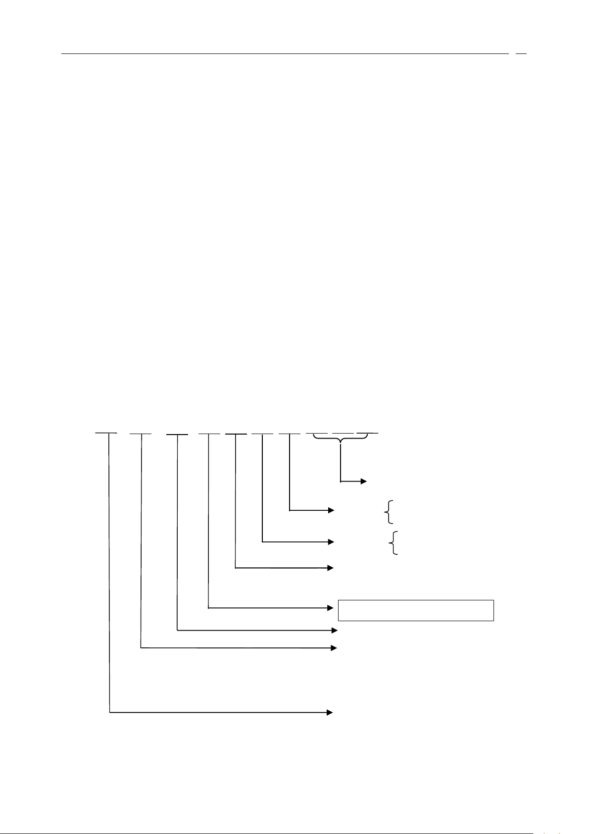
HK M □ □ □ - □ - □ - □ - □ - □ - □
Wiring diagram number (refer to table 6-2)
E: explosion proof, Exd Ⅱ BT4
W: water tight, IP68
Enclosure
S: 380ACV, 3 phase
D: 220ACV, single phase
Power supply
Output speed (rpm): 18; 24; 36; 48; 72; 96; 144; 192
Con n ect mode:A;B1;B3;B4
Flange type: F10; F14; F16
Type: HK M03; HK M0 5 ; HK M12; HK M20;
HK M5 5 . According to torque, thrust, output
speed and valve stem dimension, to refer table 41,table 4-2 and table 4-3.
HK M series
■ redundant configuration available
6.11.4 Foundation Fieldbus communication
HKM actuator may be connected to a Foundation Fieldbus network
by
the inclusion of a HKM actuator FF
module. The device complies with fieldbus standard IEC 61158-2, using a 2 wire electrical connection to the
highway and has been certified for inter-opera bility. The foundation highway exchanges data and control
between devices and full actuator functionality is available. Each actuator has full link scheduler capability and
function blocks for analogue and digital inputs and outputs as well as PID and the standard transducer block.
Foundation Fieldbus networks are capable of operating without a host system as a supervisor, the field devices
communicating directly between themselves.
Foundation fieldbus module advantages:
■ open standard protocol
■ cable cost reduction
■ installation cost reduction
■ simple to configure and use
■ access to the transducer block provides comprehensive diagnostic data
■ simple communications on plug and play basis
777
Order
Order
Order
ntroduce
III
ntroduce
ntroduce
sss
Model designation must be noted the each item, for example the wiring diagram number means the
actuators versions, and if you require order a gearbox, you need to fill upon its model number.
■ Actuator model number
Example: HK M20F14A-24- S -W- 1 01-03
Means: actuator modulating torque: 152N.M; flange type: F14; drive bush type: A; output speed: 24; Power
supply: 380ACV; enclosure: IP68 water tight; appending analogue signal input, valve position signal feedback,

28
battery low alarm
Gearbox ratio
Gearbox dimension number
Gearbox series
relay,
remote control select alarm relay and thermostat tripped alarm relay.
■ Gearbox
□ □ □
Detail information can be found on the corresponding technical data sheets.
Example: W5- 40: 1
Means: W series; dimension number: 5;gearbox ratio: 40:1.
Even if the actuator and gearbox are provided all together, the model of the gearbox is not marked on the
identification plate of the actuator. There is an individual identification plate on the gearbox; on
model of the gearbox and so on.
it
marked with
por
ImImIm
por
por
ttt
exorbitant
exorbitant
exorbitant
ant
notice:
ant
ant
notice:
notice:
output
output
output
ininin
rotate
rotate
rotate
order
order
order
tototo
speed.
speed.
speed.
advance
advance
advance
Here
Here
Here
the
orientation
the
the
orientation
orientation
advice
’’’
sss
aaa
advice
advice
the
:::
the
the
stroke
stroke
stroke
precision
precision
precision
time
time
time
popularly
,,,
popularly
popularly
not
isisis
not
not
you
you
you
less
than
less
less
than
than
dododo
252525
not
not
not
seconds.
seconds.
seconds.
select
select
select
the
the
the

29
8 、 Machining of the Drive Bush
888
.1.1.1
Thrust
Thrust
Thrust
Base
Base
Base
Type
Type
Type
:
1) Turn actuator onto its side, remove the two cap-headed screws holding base plate onto thrust base, pull
out the drive bush complete with its bearing assembly. Remove the thrust bearing of the drive bush’s double end
(The two thrust bearing stop ring ne
ar
the mid bulgy – shoulder of the drive bush may not be removed.) (Refer
to diagram1-1 ,1-2).
2) According to the thread dimension of the valve stem, machine the internal screw thread of the drive
bush.
3) Remove all swarf from the drive bush and others that removed, ensuring that they are
in
good
condition, clean and greased. According to the above steps, with adverse steps we can refit the drive bush and
base assembly on the actuator, ensuring that the sl ots
in
the drive bush are located into the drive dogs of the
hollow output shaft. (The bearing modules must be topped up lubricating oil).
8 .2 Non-Thrust Base Type (Refer to diagram 1-3).
1) Turn actuator onto its side, remove the base, the retaining clip on top of the drive bush can be seen now.
2) Turn the retaining clip slots until reach the drive dogs of the output shaft,orwith the screwdriver seek out the
retaining clip, we can remove the drive bush. According to the connection mode of the configured value, we can
machine the hole of the dr ive bush shaft, key seatorcombinative-dogs, and refit them assembly on the actuator.
Then
fit
on the retaining clip and base . Before fitting on the base, must daub between base and drive bush with
any lubricating – oil.
999
、 III
nstallation
nstallation
nstallation
ofofof
the
the
the
actuator
actuator
actuator
9.1
9.1
9.1
Installation
Installation
Installation
with
with
with
the
the
the
visible
visible
visible
stem
stem
stem
valves:
valves:
valves:
9.1.1
9.1.1
9.1.1
Install
Install
Install
the
the
the
Thrust
Thrust
Thrust
Base
Base
Base
Type
Type
Type
:
1). When leaving factory, according to the requests of the clients the screw thread inside the drive bush has
been machined well. As a combination of actuator and drive bush,
it
is assembled with valve.
Firstly
let
the hand – operating step available, then place the actuator onto valve, put the screw thread of
the actuator and the valve stem
in
order, wind the handwheel
in
the opening direction to engage the drive bush
diagram 1-1 diagram 1-2 diagram 1-3

30
onto the stem. Continue winding until the actuator is firmly down on the valve flange. Wind two further turns,
fit
securing bolts and tighten fully.
2). If the clients machine the internal screws of the drive bush, according to above 1.1, machine and
fit in
the drive bush. According to the above “ a ”,fit
them assembly.
9.1.2
9.1.2
9.1.2
Installing
Installing
Installing
the
the
the
Non
Non
Non
–––
thrust
thrust
thrust
Base
Base
Base
Type
Type
Type
Ensuring that the drive bushes of the non- thrust type have been machined, then
fit
the actuator and valve
as a combined unit.
Firstly
let
the hand – operating step of the actuator available, then place the actuator onto the valve,
let
the valve stem into the hole of the drive bush,
or
the combinative – dog of the drive bush is secured to the
combinative – dog of the valve, wind the handwheel
in
opening direction until the actuator is firmly down on
the valve flange. Wind two further turns,
fit
securing bolts and tighten fully.
9.2
9.2
9.2
Installation
Installation
Installation
with
with
with
the
the
the
valve
valve
valve
with
with
with
gear
gear
gear
case
case
case
Firstly checking that the drive bush, input shaft, key and key seat are all appropriate
or
not,
fit
the base
and drive bush assembly on the actuator firstly, then place the actuator onto the flange of the gear case correctly,
let
the input shaft of the ge
ar
case into the hole of the drive bush shaft, wind the handwheel, ensuring that the
key is located into the key – seat of the drive bush, then
fit
securing bolts and tighten fully.
9.3
9.3
9.3
Installation
Installation
Installation
with
with
with
the
the
the
hidden
hidden
hidden
–––
stem
stem
stem
valve
valve
valve
Popularly according to the 2.1.2, use the same way to assembly. But if the actuator will support thrust, we
should use the thrust – type connection with thrust bearing.
9.4
9.4
9.4
Handwheel
Handwheel
Handwheel
Sealing
Sealing
Sealing
Ensuring that sealing plug
in
center of handwheel is sealed with PTFE tape and fully tightened, ensuring
that moisture does not pass down the output shaft of the actuator.
9.5
9.5
9.5
Connecting
Connecting
Connecting
tototo
Terminals
Terminals
Terminals
and
and
and
Cable
Cable
Cable
Entry
Entry
Entry
1. According to the control orders, connect the power wires and signal wires.
2. The actuator has expert earth terminals,
in
order to ensure that persons and equipments are safe, the
actuator should be earthed credibly.
3. Only appropriate certified Explosion – Proof entry reduces, glands
or
conduit may be used
in
hazardous
locations. Ensure that threaded adaptors, Seal unused cable entries with a steel
or
brass threaded plug. In
hazardous areas an appropriately cert ified threaded blanking plug must be used.
9.6
9.6
9.6
Mounting
Mounting
Mounting
the
the
the
LCD
LCD
LCD
Screen
Screen
Screen
Correctly
Correctly
Correctly
When the actuator is located on the different orientations,inorder to make the actuator have the natural
direction of the LCD display, that is to say the charactors have natural display direction, the LCD screen of the
actuator provides four sorts of settings:
1. Installing the actuator
in
the horizontal direction (operating handwheel is upturned), the LCD screen is
mounted with a natural position.

31
2. The actuator is installed conversely (operating handwheel is gadarene
),
the charactors are displayed
reversely.
3. Installing the actuator
in
the leftward direction (operating handwheel is leftward
),
the LCD screen is
mounted near
by
the side of the flange.
4 Installing the actuator
in
the rightward direction (operating handwheel is rightward
),
the LCD screen
is mounted near
by
the side of the flange. The charactors are displayed reversely.
10 . Operating your Actuator
10.1 Operation
by
hand
The actuator provides operating handwheel and Electrical/Handwheel lever, when the actuator is
in
the
special instance, e.g. main power failed
or
the control circuit failed and so on, we can operate the actuator
by
hand. Before operating the handwheel, fi rstly
let
the mode selection switch be
in
the “ stop ”
or
“ local ” position .
To
engage handwheel drive depress the Electric/hand lever into “ Hand ” position and turn the handwheel
slowly to engage the clutch. When the actuator has been
in
the “ Hand ” step,the lever can now be released and
return to the free position
by
its clockwork spring. But the internal clutch has been latched up
in
the “ Hand ”
position. Now wind the handwheel and the output shaft will be driven, thus is the hand operating.
The clutch is ably designed,
it
prefers electric operation to hand operation. When the motor turning the
clutch will switch to the electric operating position automatically.
The switching lever may be latched up
in
the electric operating position
or
the hand operating position
by
the padlock. Please notice:if the lever is latched up
in
the hand operating position
by
the padlock, the turning of
the motor can not
let
the clut ch switch to the electric operating position automatically.
10.2 Local Operation
If you want to use local operation, you should
let
the mode selection switch (red switch)lie to the local
position and control the actuator
by
the operation switch (black switch). There are two kinds of work mode for
the local operation: push to run and m aintained, these are set
by
the setting tool. Details as follows:
Push to run
:
when you
let
the operation switch (black switch ) lie to the closing position, the actuator
will act towards the closing direction. When you release the operation switch, the operation switch will return to
the original position, the action towards the closing direction will be stopped. When you
let
the operation switch
lie to the opening position, the actuator will act towards the opening direction. Releasing the operation switch,
it
will return to the original position and the actuator wil l stop running immediately.
Maintained:
let
the operation switch locate
in
the closing position and if you release the switch,
it
will
return to the original position, but the actuator maintains acting towards the closing direction. As for opening
operation, you
let
the operation sw itch locate
in
the opening position, even if you releaseitand
letitreturn to the
original position, the actuator will maintain acting towards the opening direction.
10.3 Remote Operation
Details see the above.

32
11 . Debugging your Actuator
11.1 Intrinsically Safe Setting Tool.
The setting Tool allows parameters to be configured with non – invaded mode to suit the requirements,
it
allows parameters to be checked and failures to be diagnosed. If you want to use the setting
Tool,
you must
let
the Mode Switch locate
in
the “ local ”
or
“ Stop ” position aforehand. When a button is depressed the Setting Tool
transmits the relevant instruction to the actuator
by
infra – red pulses and must therefore be directly in front of
the actuator indicator window and
at
a distance no greater than 1 .00m.
↓
:
Downward Shift Button.
It
is used for selecting the next item of the current menu and
it
circulates
round the current menu from one item to another. That is to
say,
when the current cursor points to the last item,
depress this button again, the current cursor will return to the first item of the current menu.
+:
Plus Button. Increase / Change display function
’
s value
or
option setting.
-:Minus Button. Decrease / Change displayed function
’
s value
or
option setting.
11.2 The Actuator Display
On power up and initialize the actuator
’
s liquid crystal display (LCD) screen will show percentage open
with big font (figure 11-2), the icon of the battery’s electrical voltage is on the top right corner, alarm icon is on
the bottom right corner. When th e valve reachs to the limited position, show the valve’s open percent with the
simulant icon of the butterfly valve (Figure 11-3a,b).
When a any button (not include “ Reset Button ” ) is depressed directly
in
front of the actuator indicator
window, the LCD screen will show main menu. From the main menu you can enter into parameters setting,
parameters checking and status interrogating menu. Entering into menu, the LCD screen is divided into four
areas: Menu Area (Parameters Setting, parameters checking and status interrogating
),
Alarm Area, Clew Area
←
:
Enter Button. Enter displayed value
↖
:
Return Button.. Return from current menu to upper menu.
R:
Reset Button. When the actuator enters into trap contingently, depress this button
or
option setting.
,
the Setting Tool
will transmit a hardware resetting signal to the actuator and the actuator will recover to the nomal program
circles.
Notice: When you
let
the Mode Switch locate
in
the “ local ” position, depressing the “ + ” button and “ ↓ ” button
synchronously the actuator will execute “ Local Opening ” action, depressing the “ - ” button and “ ” button
synchronously the actuator will execute “ Local Closing ” action.
Setting Tool Model: HKC/HKM;
Explosion – Proof Mark: Exia Ⅱ CT4;
Explosion – Proof Certificate Number:
Working Condition: Temperature: -30 ℃ ~+50 ℃ ,Opposite Humidity: ≤ 95%, Atmosphere pressure :0.86
MPa ~1.06 MPa, Power Supply: two common batteries with size 5.
Attention for the use of the Setting
replacing
Setting
or
altering the components and configurations if they affect the Explosion – Proof capabilities of the
Tool;
3. Should cleanout the Setting Tool with the cleaning agent
Please notice: If the Mode Switch is lying
is running
,orthe motor stops but stillinthe “ No Acting ” time, the Setting Tool is not available.
Tool:
1. No removing the back cover
in
the “ Remote ” position ,or lying
or
dank cloth.
in
the hazardous area; 2. No
in
“ Local ” position but the motor

33
and Battery Status Display Area.(Figure 11-4).
figure 11-2 figure 11-3a figure 11-3b figure 11-4
11 .3 Main Menu
Notice
Notice
Notice
:::
InInIn
order
order
order
tototo
make
make
make
the
the
the
latter
latter
latter
depiction
depiction
depiction
and
and
and
reading
reading
reading
advantageous,
advantageous,
advantageous,
the
the
the
selected
selected
selected
item
item
item
isisis
bracketed
bracketed
bracketed
bybyby
“““
[[[
]]]
”””
brackets.
brackets.
brackets.
The
The
The
selected
selected
selected
item
item
item
isisis
shown
shown
shown
reversely
reversely
reversely
(that
(that
(that
isisis
black
black
black
underside
underside
underside
and
and
and
white
white
white
words
words
words
),),),
the
the
the
not
not
not
selected
selected
selected
item
item
item
isisis
shown
shown
shown
generally
generally
generally
(that
(that
(that
isisis
www
hite
hite
hite
underside
underside
underside
and
and
and
black
black
black
words).
words).
words).
ByByBy
the
the
the
way
way
way
,,,
“““
MMMMMM
”—”—”—
means
means
means
“““
Main
Main
Main
Menu
Menu
Menu
”””
,,,
“““
SMSMSM
”””
---
---
---
means
means
means
“““
Setting
Setting
Setting
Menu
Menu
Menu
”””
,,,
“““
CMCMCM
”””
---means
---means
---means
“““
Checking
Checking
Checking
Menu
Menu
Menu
”””
,,,
“““
IMIMIM
”””
---means
---means
---means
“““
Interrogating
Interrogating
Interrogating
Menu
Menu
Menu
”””
...
11.4 Parameters Setting [ 参数设定 ]
Before natural working we must configure the work parameters for the actuatorinadvance.
In the “ MM ” menu
,
use “ ↓ ” button to select the “ 参数设定 ” item, enter into “ Sub-M ” menu. In order to
prevent the non – accredited person from changing the function setting, the actuator provides the password
function. The “ Sub-M ” menu indicates that the operator must input password. The password is from 000 to 255.
If you enter the correct password
in
the “ Sub-M ” menu. And depress the “ ” button, you can enter into
“ SM ” menu. In this submenu there are four items: (1) [ 改变口令 ] Changing Password; (2) [ 一级设定 ] Primary
Setting; (3) [ 二级设定 ] Secondary Setting.
11.5 Changing Password [ 改变口令 ]
The Changing
Changing
Changing
Password
Password
Password
[[[
改变口令 ]]]
item allows the operator to
change the primary password and enter new password over again. In the “ SM ”
menu, you can set the new password value from 000 to 255. If the New
New
New
Password
Password
Password
[[[
新口令 ]]]isin
the range from 000 to 099, shift the cursor to row 000
and change
it
with “ + ”,“ – ” button. If the new password is
in
the range from 100 to 255, shift the cursor to row
Work
Area
clew area
5 0%
alarm area
alarm area
alarm area
alarm area
参数设定
参数检查
状态查询
【 MM 】
输入口令
【 0 0 0 】
1 0 0
【 Sub-M 】
【 SM 】
参数设定
参数检查
状态查询
【 MM 】
【 CM 】
【 IM 】
输入口令
0 0 0
1 0 0
【 Sub-M 】
改变口令
一级设定
二级设定
【 SM 】
【 SM 1 】
【 SM 2 】
新口令
0 0 0
1 0 0
新口令
【 0 0 0 】
1 0 0
【 SM.PW-C 】
【 改变口令 】
一级设定
二级设定
【 SM 】

34
100 and change
it
with “ + ”,“ – ” button. When the shown passwords are the value that you require, depress the
“ ” button and confirm the password.
Notice
Notice
Notice
:::
InInIn
the
the
the
latter
latter
latter
parameters
parameters
parameters
setting,
setting,
setting,
ififif
nonono
special
special
special
explanation,
explanation,
explanation,
after
after
after
confirming
confirming
confirming
the
the
the
setting
setting
setting
parameters,
parameters,
parameters,
only
only
only
when
when
when
the
the
the
displayed
displayed
displayed
word
word
word
“““
已存 ”””
(this
(this
(this
words
words
words
are
are
are
displayed
displayed
displayed
ininin
the
the
the
Clew
Clew
Clew
Area)
Area)
Area)
flashes,
flashes,
flashes,
the
the
the
actuator
actuator
actuator
will
will
will
receive
receive
receive
this
this
this
setting
setting
setting
and
and
and
return
return
return
back
back
back
tototo
the
the
the
upper
upper
upper
menu.
menu.
menu.
11.6 Primary Setting [ 一级设定 ] .
In the “ SM ” menu, use “ ↓ ” button
select the Primary Setting[ 一级设定 ] item
and depress the “ ” button, enter into
“ [SM1] ” menu.
11 .6.1 Setting of the Display selection [ 显示
选择 ]
When the actuator
’
s installing
direction is reverse with our line of sight, this option is used to adjustitin
order to make the menu converse to
be seen naturally.In the “ SM1 ” menu
,
use “ ↓ ” button to select Display
Display
Display
Selection
Selection
Selection
[ 显示选择 ] item, depress
“ ” button and enter into “ SM1.1 ” menu. The LCD screen’s Natural
Natural
Natural
Display
Display
Display
[ 正显示 ] and Reverse
Reverse
Reverse
Display
Display
Display
[ 反显示 ] are shown
in
the figure 11-5.
11.6.2 Local Control Mode [ 就地控制 ]
In the “ SM1 ” menu
,
use “ ↓ ” button
to select [[[
就地控制
]]]
( Local
Local
Local
Control
Control
Control
)
ite m,
depress “ ” button and enter into “ SM1.2 ”
menu.
You
can select Push
Push
Push
tototo
Run
Run
Run
[[[
点动 ]]]
or
Maintained
Maintained
Maintained
[[[
保持 ]]]
. Select the required
mode and depress “ ” button
,
the menu
will return to the "SM1 ” menu automatically .
11 .6.3 Direction to Close [ 关闭方向 ]
We
can select the running direction of the output shaftbythe [ 关闭方向
]
( Direction
Direction
Direction
tototo
CCC
lose
lose
lose
)
item .I
n
the “ SM1 ” menu, use “ ↓ ” button to select Direction
Direction
Direction
tototo
Close
Close
Close
[ 关闭方向 ] item, depress “ ” button and enter
into “ SM1.3 ” menu.
You
can select the required closing - direction
by
the “ ↓ ” button. When select Clockwise
to Turn [ 顺时针转 ] item the output shaft will clockwise turn;
by
contraries,itwill anti-clockwise turn.
11.6.4 Closing Protection [ 关闭保护 ]
【显示选择】
就地控制
关闭方向
关闭保护
打开保护
远控优先
关闭限位
打开限位
【 SM 1 】
【正显示】
反显示
【 SM 1.1 】
【显示选择】
就地控制
关闭方向
关闭保护
打开保护
远控优先
关闭限位
打开限位
【 SM 1 】
改变口令
【 一级设定 】
二级设定
【 SM 】
figure 11 -5
就地控制
【点动】
保持
【 SM 1.2 】
显示选择
【就地控制】
关闭方向
关闭保护
打开保护
远控优先
关闭限位
打开限位
【 SM 1 】
关闭方向
【顺时针转】
逆时针转
【 SM 1.3 】
显示选择
就地控制
【关闭方向】
关闭保护
打开保护
远控优先
关闭限位
打开限位
【 SM 1 】

35
This item is used to select the values of the over
torque protection and decide that if the limited position
protection is required
or
not.
In the “ SM1 ” menu, use “ ↓ ” button to select
Closing
Closing
Closing
Protection
Protection
Protection
[ 关闭保护 ] item, depress “ ” button
and enter into “ SM1.4 ” menu
,
that is T orque
Torque
Torque
Protection
Protection
Protection
[ 保护转矩 ] item.
You
can select the required values of the
torque protection (the range can be varied between 40% and
127% rated torque
),
depress the “ ” button and enter into “ SM1.4.1 ” menu. In this menu, you also select the
mode of the Limit
Limit
Limit
Protection
Protection
Protection
[ 限位保护 ] for the closing direction: that is “
Yes
Yes
Yes
” [ 有 ]
or
“ NoNoNo
” [ 无 ] . Depress the
“ ” button
in
order to actuator can receive these setting.
Explanation: If you select “ No ” [ 无 ] option as the Limit
Limit
Limit
Protection[
Protection[
Protection[
限位保护 ]]],when the actuator is
closing, only if the torque is over the actuator will stop running. If you select “
Yes
” [ 有 ] option as the limit
position protection, when the actuator closing, the Over Torque
or
Limit
Limit
Limit
Close
Close
Close
ddd
[ 关闭限位 ] is detected, the
actuator will stop running.
Notice
Notice
Notice
Notice
2:2:2:
IfIfIf
the
the
the
over
over
over
torque
torque
torque
appears
appears
appears
when
when
when
the
the
the
actuator
actuator
actuator
isisis
running
running
running
ininin
aaa
certain
certain
certain
direction,
direction,
direction,
the
the
the
actuator
actuator
actuator
will
will
will
register
register
register
this
this
this
information,
information,
information,
even
even
even
ififif
the
the
the
actuator
actuator
actuator
resets
resets
resets
ororor
power
power
power
upupup
over
over
over
again
again
again
this
this
this
note
note
note
isisis
still
still
still
maintained
maintained
maintained
and
and
and
nonono
running
running
running
towards
towards
towards
this
this
this
direction
direction
direction
iii
sss
allowed.
allowed.
allowed.
There
There
There
are
are
are
two
two
two
ways
ways
ways
tototo
eliminate
eliminate
eliminate
this
this
this
note:
note:
note:
(1)
(1)
(1)
running
running
running
towards
towards
towards
reverse
reverse
reverse
direction;
direction;
direction;
(2)
(2)
(2)
setting
setting
setting
the
the
the
torque
torque
torque
protection
protection
protection
value
value
value
over
over
over
again.
again.
again.
11 .6.5 Opening Protection [ 打开保护 ]
This item is used to select the values of the over
torque protection and decide that if the limit position
protection is required
or
not. The setting way is similar
to the one of the “ closing protection ” .
Refer to the following table for limit position
protection
or
refer to the used valve for recommended
selection.
11.6.6 Remote Control Priority [ 远控优先 ]
When the Remote
Remote
Remote
Opening
Opening
Opening
[ 远程打开 ] and Remote Closing [ 远程关闭 ] signal existatthe same time,
this item is used to decide that who has the priority.
Valve Type
Closing Limit Protection
Opening Limit Protection
Wedge gate, Cute-off
No
Yes
Butterfly, Ball, Thru-conduit,
Plug , Parallel Slide
Yes
Yes
显示选择
就地控制
关闭方向
【关闭保护】
打开保护
远控优先
关闭限位
打开限位
【 SM 1 】
保护转矩
【 40% 】
【 SM 1.4 】
限位保护
【有】
无
【 SM 1.4.1 】
显示选择
就地控制
关闭方向
关闭保护
【打开保护】
远控优先
关闭限位
打开限位
【 SM 1 】
保护转矩
【 40% 】
【 SM 1.5 】
限位保护
【有】
无
【 SM 1.5.1 】
1:
this item
,
refer to the last of the instructions---- “ Important Notices ” .

36
In the “ SM1 ” menu, use “ ↓ ”
button to select “ Remote Control
Priority ” item, depress “ ” button and
enter into “ SM1.6.1 ” menu. Use “ ↓ ”
button to select the relevant function.
When select Open
Open
Open
Firstly
Firstly
Firstly
[ 打开优先 ],if
Remote
Remote
Remote
Opening
Opening
Opening
[ 远程打开 ] and
Remote
Remote
Remote
Closing
Closing
Closing
[ 远程关闭 ] signal exist
at
the same time, only execute the opening action. When select Close
Close
Close
Firstly
Firstly
Firstly
[ 关闭优先 ],if Remote
Remote
Remote
Opening
Opening
Opening
[ 远程打开 ]]]
and Remote
Remote
Remote
Closing
Closing
Closing
[ 远程关闭 ] signal existatthe same time, only execute the close
action.
If you have selected your required item, you will depress the “ ” button and the menu returns back to the
“ SM1 ” menu.
11.6.7 Limit Closed [ 关闭限位 ]
When the actuator is lying
in
the Limit Closed position the Limit
Limit
Limit
Closed
Closed
Closed
[ 关闭限位 ]]]
item is used to set
the valve position value of this moment.
Turn valve manually to the full closed position. Allow for overrun
by
winding actuator output open up to
one turn. In the “ SM1 ” menu, use “ ↓ ” button to select the “ Limit Closed ” item, depress “ ” button and the
actuator will receive the current valve position values. At this moment the red lamp should illuminate.
11 .6.8 Limit Open [ 打开限位 ]
When the actuator is lying
in
the open limit position the Limit
Limit
Limit
Open
Open
Open
[ 打开限位 ] item is used to set the
valve position value of this moment.
T
urn valve manually to the full open position. Allow for overrun
by
winding actuator output closed up to
one turn. In the “ SM ” menu, use “ ↓ ” button to select the Limit
Limit
Limit
Open
Open
Open
[[[
打开限位 ] item, depress the “ ” button
and the actuator will receive the current valve position values. At this moment the green lamp should illuminate.
When you set the Limit
Limit
Limit
Open
Open
Open
[ 打开限位 ],from closed limit position to open limit position there are 3.5
turns
at
the least for the output shaft of the actuator,orelse the actuator will not receive the settings.
11 .7 Secondary Settings [ 二级设定 ]
The Secondary
Secondary
Secondary
Settings
Settings
Settings
[ 二级设定 ] are the higher level for the
actuator, so that we can control the actuator
in
the higher level.
The Secondary Settings include: (1) Relay
Relay
Relay
Group
Group
Group
[ 继电器组 ];(2)
Remote
Remote
Remote
Control
Control
Control
III
nactive
nactive
nactive
[ 远控禁动 ];(3) ESD
ESD
ESD
(Emergency
(Emergency
(Emergency
shutdown)
shutdown)
shutdown)
[ 紧
急动作 ];(4) Analog
Analog
Analog
Input
Input
Input
[ 模拟输入 ];(5) Timing
Timing
Timing
Operation
Operation
Operation
[ 定时操作 ]
;
远程手动
【打开优先】
【关闭优先】
【 SM 1.6.1 】
显示选择
就地控制
关闭方向
关闭保护
打开保护
【远控优先】
关闭限位
打开限位
【 SM 1 】
显示选择
就地控制
关闭方向
关闭保护
打开保护
远控优先
【关闭限位】
打开限位
【 SM 1 】
显示选择
就地控制
关闭方向
关闭保护
打开保护
远控优先
关闭限位
【打开限位】
【 SM 1 】
改变口令
一级设定
【二级设定】
【 SM 】
继电器组
远控禁动
紧急动作
模拟输入
定时操作
惯性制动
禁动时间
【 SM 2 】
Notice:
you have set the “ Limit Closed ”,you must set the “ Limit Open ” over again,
You
should set the Limit Closed[ 关闭限位 ] firstly then set the Limit Open [ 打开限位 ] . When
or
else the actuator will not receive
the settings and don ’twork naturally.

37
(6) Inertia
Inertia
Inertia
Trig
Trig
Trig
[ 惯性制动 ];(7) Inactive
Inactive
Inactive
Time
Time
Time
[ 禁动时间 ] .
11.7.1 Relay Group [ 继电器组 ] (that is
indication relays S1, S2, S3 and S4)
S1 to S4 relay is used to indicate
Closed
Closed
Closed
End
End
End
Position[
Position[
Position[
阀门全
关 ]]]
,Open
,Open
,Open
End
End
End
Position[
Position[
Position[
阀门全开 ]]]
,,,
Torque
Torque
Torque
Trip
Trip
Trip
Mid-travel[
Mid-travel[
Mid-travel[
中途过矩 ]]]
,,,
Actuator
Actuator
Actuator
Closing[
Closing[
Closing[
正在关闭 ]]]
,,,
Actuator
Actuator
Actuator
Opening
Opening
Opening
[[[
正在打开 ]]]
,,,
Actuator
Actuator
Actuator
Rotating
Rotating
Rotating
[[[
正在动作 ]]]
,,,
Motor
Motor
Motor
Stalled
Stalled
Stalled
[[[
电机失速 ]]]
,,,
Torque
Torque
Torque
Trip
Trip
Trip
Close
Close
Close
[[[
关闭过矩 ]]]
,,,
Torque
Torque
Torque
Trip
Trip
Trip
Open
Open
Open
[[[
打开过
矩 ]]]
,,,
Battery
Battery
Battery
Low
Low
Low
[[[
电池电低 ]]]
,,,
Valve
Valve
Valve
Position
Position
Position
Open
Open
Open
Percent
Percent
Percent
[[[
阀位开度 ]]]
...
When the relay is sprung, the contact mode may be set normally open
or
normally closed .Make S1 as an
exemplar: In the “ SM2 ” menu we can select the “ 继电器组 ”,depress the “ ” button and enter into the “ SM2.1 ”
menu. Use the “ ↓ ” button to select “ S1S1S1
设置 ” ( S1S1S1
setting
setting
setting
) item and enter into “ SM2.2.1 ” menu. Use “ ↓ ”
button to select the required contact mode and depress “ ” button.
When you enter into “ SM2.2.1 ” menu and select the V alve
Valve
Valve
Position
Position
Position
Open
Open
Open
Percent
Percent
Percent
[[[
阀位开度 ]]],depress
the “ ” button and enter into the “ SM2.1.3 ” menu, use “ + ”,“ - ” button to select the valve position values,
depress the “ ” button and enter into the “ SM2.1.2 ” menu.
11.7.2 Remote Control Inactive [ 远控禁动 ]
This function is used to decide that
the actuator is inactive
or
not
by
two wires
.By the “ ↓ ”,“ ” button select the “ Remote
Remote
Remote
Control
Control
Control
Inactive
Inactive
Inactive
” [ 远控禁动 ] item, enter
into “ SM2.2 ” menu, this item is set as
“ Allowed
Allowed
Allowed
” [ 允许 ]]]
or
“ Not
Not
Not
Allowed
Allowed
Allowed
” [ 不允
许 ] . When you set this item as [ 允许 ]
,
actuator allows the inactive function for the
close direction and open direction has the inactive function, you should connectajumper wire to the inactive
signal terminal port of another direction. According to the right figure’s connection mode, you can realize the
inactive function of the open direction (when the switch turn off), but there’s no inactive function of the close
direction. If you set this item as “ Not Allowed ”,the inactive signal that is adscititious is not available.
【继电器组】
远控禁动
紧急动作
模拟输入
定时操作
惯性制动
禁动时间
【 SM 2 】
【 S1 设置】
S2 设置
S3 设置
S4 设置
【 SM 2.1 】
【阀门全开】
阀门全关
中途过矩
正在关闭
正在打开
正在动作
电机失速
打开过矩
关闭过矩
电池电低
阀位开度
【 SM 2.1.1 】
触点方式
【吸合】
断开
【 SM 2.1.2 】
阀位开度
55%
【 SM 2.1.3 】
继电器组
【远控禁动】
紧急动作
模拟输入
定时操作
惯性制动
禁动时间
【 SM 2 】
不允许
【 打开允许】
关闭允许
【 SM 2.3 】
【高信有效】
低信有效
【 SM 2.3.1 】
电机过热
【停动】
不停动
【 SM 2.3.1.1
】
certain given status of the actuator, that is
one of the
relay,
S1 to S4, may be sprung
the one of the following status:
a
by

38
11.7.3 ESD (Emergency Shutdown) [ 紧急动作 ]
This function is used to control the actuator’s action
in
the emergent circumstances.
In the “ SM2 ” menu, use “ ↓ ” button to select the “ ESD
ESD
ESD
” item, depress “ ” button and enter into
“ SM2.3 ” menu.
You
can select this item as Not
Not
Not
Allowed
Allowed
Allowed
[ 不允许 ] (ESD function is void), Open
Open
Open
Allowed
Allowed
Allowed
[ 打开
允许 ] (the actuator will execute the open action when the ESD happens) and Close
Close
Close
Allowed
Allowed
Allowed
[ 关闭允许 ] (the
actuator will execute the close action when the ESD happens). If you select Not Allowed [ 不允许 ] item, depress
the “ ” button, return back to the “ SM2 ” menu. If you select Open
Open
Open
Allowed
Allowed
Allowed
[ 打开允许 ]
or
Close
Close
Close
Allowed
Allowed
Allowed
[ 关
闭允许 ] item, depress “ ” button and enter into “ SM2.3.1 ” menu. In this menu if you select the High-V oltage
High-Voltage
High-Voltage
Active
Active
Active
[ 高信有效 ],when the ESD signal is high level the actuator can execute the ESD function; if you select
the Low-Voltage
Low-Voltage
Low-Voltage
Active
Active
Active
[ 低信有效 ],when the ESD signal is low level the actuator can execute the ESD
function. Depress the “ ” button and enter into “ SM2.3.1.1 ” menu, this menu requires that the user must decide
the selections when the ESD is active and the motor is over temperature. If you select Not
Not
Not
Stop
Stop
Stop
Running
Running
Running
[ 不停
动 ],when the ESD is active and the motor is over temperature, the actuator will run to the configured position,
in
this case the motor may be damaged. If you select Stop
Stop
Stop
Running
Running
Running
[ 停动 ] item, when the ESD is active and the
motor is over temperature the actuator will not run.
The ESD function doesn ’toverride the following functions: (1) Limit
Limit
Limit
Protection
Protection
Protection
[ 限位保护 ];(2) Over
Over
Over
Torque
Torque
Torque
Protection
Protection
Protection
[ 过矩保护 ];(3) Remote
Remote
Remote
Control
Control
Control
Inactive
Inactive
Inactive
[ 远控禁动 ];(4) Mode Switch
in
the Stop
Position.
11.7.4 Analog Input [ 模拟输入 ]
This function is used to control the actuator run to
the appointed position
by
the external electrical current
signal.
In the “ SM2 ” menu, select the Analog
Analog
Analog
Input
Input
Input
[[[
模拟
Notice:Inactive signal Effective
means the terminal’s voltage is zero
继电器组
【远控禁动】
紧急动作
模拟输入
定时操作
惯性制动
禁动时间
【 SM 2 】
【 允许】
不允许
【 MS2.2 】
Opening inactive
Control contact
Control room
actuator
53731438
Opening inactive
Closing inactive
继电器组
远控禁动
紧急动作
【模拟输入】
定时操作
惯性制动
禁动时间
【 SM 2 】
【 信号量程】
死区
低信阀位
高信阀位
丢信动作
【 SM 2.4 】
【 10mA 】
20mA
【 SM 2.4.1 】

39
输入 ]]]
item, depress the “ ” button and enter into “ SM2.4 ” menu.
11.7.4.1 Signal Range [ 信号量程 ]
This function is use to select the range of the external DC analog electrical current
or
voltage that is
inputted the actuator.
In the “ SM2.4 ” menu, select the Signal
Signal
Signal
Range
Range
Range
[ 信号量程 ] item, depress the “ ” button and enter into
the “ SM2.4.1 ” menu. In this menu, the “ 10mA ” means that the analog signal’s input range is between 2mA and
10mA / between 0.5VDC and 2.5VDC, another item is “ 20mA ”,that means 4mA~20mA /1VDC~5VDC.
11.7.4.2 Deadband Adjustment
The deadband means that the least percent open of the valve’s
position when the actuator runs again. This value is relative to the running
stroke of the actuator.
In the “ SM2.4 ” rnenu, select the Deadband
Deadband
Deadband
[ 死区 ] item, depress the
“ ” button and enter into the “ SM2.4.2 ” menu. Use the “ + ”
or
“ - ” key to
select the deadband width. The range is 0.1% ~ 9.9%.
If the actuator hunts
or
responds unnecessarily to
a
fluctuating set point signal the deadband must be
increased. If more accurate control is required the deadband may be decreased.
11.7.4.3
Valve
Position Low Signal Settings
This function is used to set the low point signal of the analog
electrical current input.Itis used for the calibration account.
Input the low point signal to the sunflower connection terminals
[27(-),26(+)]. In the “ SM2.4 ” menu, select the V alve
Valve
Valve
Position
Position
Position
ofofof
Low
Low
Low
Voltage
Voltage
Voltage
[ 低信阀位 ] item, depress the “ ” key and enter into the
“ SM2.4.4 ” menu. Use “ + ”
or
“ - ” key to select the value, the range is 0~100%.
Depress the “ ”
key,
the actuator will register this value and take
it
as one of the emendation of the analog input
signal.
11.7.4.4 Valve Position High Signal Settings
This function is used to set the high point signal of the analog
electrical current input.
Input the high point signal to the sunflower connection terminals
[27(-),26(+)]. In the “ SM2.4 ” menu, select the
Vale
Vale
Vale
Position
Position
Position
ofofof
High
High
High
Voltage
Voltage
Voltage
[ 高信阀位 ] item, depress the “ ” key and enter into the “ SM2.4.5 ”
信号量程
【 死区】
低信阀位
高信阀位
丢信动作
【 SM 2.4 】
3 %
【 SM 2.4.2 】
信号量程
死区
【 低信阀位】
高信阀位
丢信动作
【 SM 2.4 】
对应阀位值
00%
【 SM 2.4.4 】
信号量程
死区
低信阀位
【 高信阀位】
丢信动作
【 SM 2.4 】
对应阀位值
100%
【 SM 2.4. 5 】

40
menu. Use “ + ”
or
“ - ” key to select the value, the range is 0%~100%. Depress the “ ”
key,
the actuator will
register this valve and take
it
as another one of the emendation of the analog input signal.
11 .7.4.5 Action On Loss of Signal
Action on loss of signal is used to select the actuator
’
s action mode
when the analog electrical current signal lost.
In the “ SM2.4 ” menu, use “ ↓ ” key to select the Action
Action
Action
OnOnOn
Loss
Loss
Loss
ofofof
Signal
Signal
Signal
[ 丢信动作 ] item and enter into the “ SM2.4.6 ” menu. Use “ ↓ ” key to
select NoNoNo
Action
Action
Action
[ 不动作 ]]],Valve
Valve
Valve
Position
Position
Position
ofofof
Low
Low
Low
Voltage
Voltage
Voltage
[ 低信阀位 ]
or
Valve
Valve
Valve
Position
Position
Position
ofofof
High
High
High
Voltage
Voltage
Voltage
[ 高信阀位 ] . If you select V alve
Valve
Valve
Position
Position
Position
ofofof
Low
Low
Low
Voltage
Voltage
Voltage
[ 低信阀位 ],the
actuator will run to the position corresponding to low point signal. If you select Valve
Valve
Valve
Position
Position
Position
ofofof
High
High
High
Voltage
Voltage
Voltage
[ 高信阀位 ] the actuator will run to the position corresponding to high point signal. When the input
signal is less than half of the low point signal, we think that this is the loss of signal.
11.7.5 Timing Operation [ 定时操作 ]
The Timing Operation is an optional function. When the actuator is opening
or
closing,
in
order to make
the actuator act intermittently, we use this “ Timing Operation ” . The timing operation enables pulsed “ stop/start ”
operation
by
the actuator. This effec tively increases the valve stroke time and can be adjusted to prevent
hydraulic shock (water hammer) and flow surges
in
pipelines.
In the “ SM2 ” menu, use “ ↓ ” key to select the Timing
Timing
Timing
Operation
Operation
Operation
[ 定时操作 ] item, depress the “ ” key
and enter into the “ SM2.5 ” menu, to select Allow [ 允许 ]
or
Not
Not
Not
Allowed
Allowed
Allowed
[[[
不允许 ] . Select Allowed
Allowed
Allowed
[ 允许 ] and
enter into “ SM2.5.1 ” . Use the “ ↓ ” key to select the Timing Position [ 定时位置 ] item, enter into the
“ SM2.5.1.1 ” menu . U se “ ↓ ” key to select the Open
Open
Open
Position
Position
Position
Effective
Effective
Effective
[ 开位有效 ] item, depress the “ ” key
and enter into the “ SM2.5.1.1.1 ” menu, Use “ + ”
or
“ - ” key to select the Valve
Valve
Valve
Position
Position
Position
tototo
Stop
Stop
Stop
[ 停动阀位 ] and
Valve
Valve
Valve
Position
Position
Position
tototo
Start
Start
Start
[ 起动阀位 ],then use “ ” key to return back to the “ SM2.5.1 ” menu. If you select the
Close
Close
Close
Position
Position
Position
Effective
Effective
Effective
[ 关位有效 ] . In the “ SM2.5.1 ” menu, select the Active
Active
Active
Time
Time
Time
[ 动作时间 ] item and enter
into the “ SM2.5.1.2 ” menu. Use “ + ”
or
“ - ” key to set the time. “ Inactive Time ” item’s setting is similar to the
“ Active Time ” item. The range of active / inactive time is 1~99 seconds.
Open
Open
Open
Position
Position
Position
Effective
Effective
Effective
[ 开位有效 ] is the pulsing operation when the actuator acts intermittently
around the open limit position.
Close
Close
Close
Position
Position
Position
Effective
Effective
Effective
[ 关位有效 ] is the pulsing operation when the actuator acts intermittently
around the closed limit position.
Active
Active
Active
Time
Time
Time
[ 动作时间 ] is the duration when the actuator executes the “ Timing Operation ” function.
Inactive
Inactive
Inactive
Time
Time
Time
[ 禁动时间 ] is the rest time when the actuator executes the “ Timing Operation ” function.
Valve
Valve
Valve
Position
Position
Position
tototo
Stop
Stop
Stop
[ 停动阀位 ] is the valve position that the close position is effective and that after
信号量程
死区
低信阀位
高信阀位
【 丢信动作】
【 SM 2.4 】
【 不动作 】
低信阀位
高信阀位
【 SM 2.4. 5 】

41
the opening action when the actuator stops the “ Timing Operation ” function;
or
the valve position that the open
position is effective and that after the closing action when the actuator stops the “ Timing Operation ” function.
Valve
Valve
Valve
Position
Position
Position
tototo
Start
Start
Start
[ 起动阀位 ] is the valve position that the close position is effective and that after
the closing action when the actuator starts the “ Timing Operation ” function;
or
the valve position that the open
position is effective and that after the opening action when the ac tuator starts the “ Timing Operation ” function.
The Timing Operation
’
s timing diagram is as follows:
关闭控制信号: CCC
losing
losing
losing
control
control
control
signal
signal
signal
打开控制信号: Opening
Opening
Opening
control
control
control
signal
signal
signal
关闭动作: Closing
Closing
Closing
action
action
action
打开动作: Opening
Opening
Opening
action
action
action
阀位值: Valve
Valve
Valve
position
position
position
value
value
value
开阀限位: Limit
Limit
Limit
Open
Open
Open
关阀限位: Limit
Limit
Limit
Closed
Closed
Closed
11 .7.6
.7.6
.7.6
Inertia
Inertia
Inertia
Trig
Trig
Trig
[[[
惯性制动 ]]]
The inertia trig is used to give an reverse energy to the motor and make the motor stop quikly so that we
can obtain an accurate valve position control.
打开控制信号
打开动作
阀位值
开阀限位
停动阀值
关阀限位
关闭动作
阀位值
开阀限位
起动阀值
关阀限位
关闭控制信号
关闭控制信号
关阀动作
阀位值
打开控制信号
关阀限位
开阀限位
停动阀值
开阀限位
关阀限位
起动阀位
打开动作
阀位值
继电器组
远控禁动
紧急动作
模拟输入
【定时操作】
惯性制动
禁动时间
【 SM 2 】
【允许】
不允许
【 SM 2.5 】
不允许
【 打开允许】
关闭允许
【 SM 2.5.1 】
3s
【 MS2.5.1.2 】
停动阀位
XX%
起动阀位
XX%
【 SM 2.5.1.1.1
】
【 开位有效】
关位有效
【 SM 2.5.1.1 】

42
In the “ SM2 ” menu, select the “ Inertia
Inertia
Inertia
Trig
Trig
Trig
” [ 惯性制动 ] item
and enter into the “ SM2.6 ” menu, use “ ↓ ” and “ ” key to select the
Allowed
Allowed
Allowed
[ 允许 ]
or
Not
Not
Not
Allowed
Allowed
Allowed
[ 不允许 ] item. Because of affecting the
motor and screw stem this function is not used commandingly.
Notice:HKC range actuator has no “ Inertia Trig ” function.
11.7.7 Inactive Time [ 禁动时间 ]
The Inactive Time is the interim time of the actuator between the two
consecutive actions, its value is 0.1s~9.9s. Because of overriding the
prescriptive startup frequency is not allowed (HKC range startup frequency is
60 times per one hour, HKM range is 1200 times per one hour),inorder to
ensure this frequency we should configure the “ Inactive Time ” properly.
In the “ SM2 ” menu, use “ ↓ ” and “ ” key to select the Inactive
Inactive
Inactive
Time
Time
Time
[ 禁动时间 ] item, depress the “ ” key and enter into the “ SM2.7 ” menu .
Use “ + ”
or
“ - ” key to select the required inactive time and depress “ ” key.
11.8 Parameters Checking [ 参数检查 ]
This function is used to check the configured work
parameters.
In the “ MM ” menu, use “ ↓ ” key to select the “ 参数检
查 ” [ Parameters
Parameters
Parameters
Checking
Checking
Checking
] item, depress the “ ” key and
enter into “ CM ” menu. “ Parameters Checking ” menu is the
same as the “ 参数设定 ” [ Parameters
Parameters
Parameters
Setting
Setting
Setting
] . Enter into the
corresponding checking menu, if the Parameters Setting
value is
a
numerical value then display the current setting
value; if the Parameters Setting value is an option then the
selected option will be display with the black bottom and
whit e word
in
the corresponding menu.
e.g. Checking the setting value of the local control:
In the “ CM1 ” menu, use “ ↓ ” key to select the “ 就地控制 ” [ Local
Local
Local
Control
Control
Control
] item. depress “ ” key and
enter into the “ CM1.1 ” menu. Observing this menu, if the “ 点动 ”””
[[[
Push
Push
Push
tototo
Run
Run
Run
] is displayed with black bottom
and white word that means the current value of the “ 就地控制 ” item is “ 保持 ” [ Push
Push
Push
tototo
Run
Run
Run
]]]
. If the “ 保
持 ” [ Matained
Matained
Matained
] string is displayed with black bottom and white word that means the current value of the “ 就地
0.1s
【 SM 2. 7 】
继电器组
远控禁动
紧急动作
模拟输入
定时操作
惯性制动
【禁动时间】
【 SM 2 】
允许
不允许
【 SM 2. 6 】
继电器组
远控禁动
紧急动作
模拟输入
定时操作
【 惯性制动 】
禁动时间
【 SM 2 】
【点劝】
保持
【 CM 1.1 】
显示选择
【就地控制】
关闭方向
关闭保护
打开保护
远控优先
关闭限位
打开限位
【 CM 1 】
【 一级参数 】
二级参数
【 CM 】
参数设定
【 参数检查】
状态查询
【 MM 】
一级参数
二级参数
【 CM 】

43
控制 ” item is “ 保持 ” . The other items are similar to this.
11.9 Status Interrogating [ 状态查询 ]
This function is used to interrogate the working circumstances of the actuator. If the working status is
not natural, we can find the failure’s position quickly
by
this function.
In the “ MM ” menu, use “ ↓ ” key to select the “ [ 状态查询 ] ” item. depress “ ” key and enter into the
“ IM ” menu.
11.9.1
Valve
Position Signal [ 阀位信号 ]
You
can know the working status about the valve position
’
s count value.
In the “ IM ” menu, use “ ↓ ” key to select the “ [ 阀位信号 ] ” item.
depress the “ ” key and enter into the “ IM.1 ” menu. In the “ IM.1 ” menu, the
signals of the valve position sensor
A
and B are displayed. At this time you can
let
the output shaft of the actuator turn
by
the local electric operation
or
hand
operation. When the sensor ene rgized
a
square wave “ ” is displayed,
or
else there’s spacing, with the turning of the actuator’s output shaft and if the
valve position sensor
A
and B natural, the “ IM.1 ” menu should be displayed and the square wave “ ”
should be flashing. By this interrogating, we can know that the correlative parts of the valve position board and
the main control board are naturalornot.
11.9.2 Switch Signal [ 旋钮信号 ]
By this we can know that the switch board and the
junctures are natural
or
not. Use “ ↓ ” key to select the
“ Switch Signal ” item. depress “ ” key and enter into the
“ IM.2 ” menu. Use “ ↓ ” key to select the required Option,
depress “ ” key and enter into “ IM2.1 ” menu. In the
“ IM2.1 ” menu you can see the results.
Remote
Remote
Remote
Position
Position
Position
[ 远程位置 ] ----- When the Mode
Switch is
in
the “ Remote Position ”,the “ 是 ” string should
be displayed,or
else the “ 否 ” is displayed,when you use this operation you should close all remote signal
or
else the actuator may run .
Local
Local
Local
Position
Position
Position
[ 就地位置 ] ------ When the Mode Switch
in
the “ Local Position ”,should display “ 是 ”
or
else display “ 否 ” .
When excuting the following items,if you don ’twant that the actuator runs
,
you should
let
the mode switch
in
the “ Stop ” position .
【阀位信号】
旋钮信号
远控信号
继电器组
电流信号
监视继电器
主控状态
当前转矩
【 I M 】
传感器 A
传感器 B
【 IM .1 】
阀位信号
【旋钮信号】
远控信号
继电器组
电流信号
监视继电器
主控状态
当前转矩
【 IM 】
有 / 无信号
【 IM .2.1 】
【远程位置】
就地位置
打开操作
关闭操作
【 IM .2 】

44
Opening
Opening
Opening
Operation
Operation
Operation
[ 打开操作 ] ------ Operation Switch (black switch) is
in
the “ Opening position ”
,
should display “ 是 ”,or
else display “ 否 ” .
Closing
Closing
Closing
Operation
Operation
Operation
[ 关闭操作 ] ------ Operation Switch is
in
the “ Closing ” position
,
should display “ 是 ”
,
or
else display “ 否 ” .
11 . 9 .3 Remote Control Signal [ 远控信号 ]
By this,we can know that the correlative parts of the
remote control board and the main control board are
naturalornot .
Before this operation
,
should
let
the Mode Switch locate
in
the “ Local Position ”
or
“ Stop Position ” .
In the “ IM ” menu
,
use “ ↓ ” key to select the “““
远控信
号 ”””
[[[
Remote
Remote
Remote
Control
Control
Control
Signal
Signal
Signal
] item
,
then depress “ ← ” key
and enter into “ MI.3 ” menu . Firstly explain the following
items (following are all the voltage of the actuator
’
s sunflower function box) :
“ 远程打开 ” [ Remote
Remote
Remote
Opening
Opening
Opening] ------
when the remote opening signal is high level should display “““
是 ”””
[[[
Yes]
Yes]
Yes]
,
or
else display “““
否 ”””
[No]
[No]
[No]
.
“ 远程关闭 ” [ Remote
Remote
Remote
Closing
Closing
Closing
] ------ when the remote closing signal is high level,should display “ 是 ”,or
else
display “ 否 ”””
.
“ 远程保持 ” [ Remote
Remote
Remote
Maintained
Maintained
Maintained
] ------ when the remote maintained signal is high level,should display “ 是 ”
,
or
else display “ 否 ” .
“ 紧急动作 ” [ ESD
ESD
ESD
]]]
------ when the ESD takes high level as effective value and the ESD signal is high level
,
should display “ 是 ”;when the ESD takes the low level as effective value and the ESD signal is low level
,
should display “ 是 ”,or
else is “ 否 ” .
“ 开阀禁动 ” [ Opening
Opening
Opening
Inactive
Inactive
Inactive
] ------ when the “ Opening Inactive ” signal is low level,should display “ 是 ”,or
else “ 否 ” .
“ 关阀禁动 ” [ Closing
Closing
Closing
Inactive
Inactive
Inactive
] ------ when the “ Closing Inactive ” signal is low level,should display “ 是 ”,or
else “ 否 ” .
“ 远程自动 ” [ Remote
Remote
Remote
Automatic
Automatic
Automatic
] ------ when the “ Remote Automatic ” signal is high level,should display “ 是 ”
,orelse “ 否 ” .
In the “ IM .3 ” menu use “ ↓ ” key to select the required item
,
depress “ ← ” key and enter into the
“ IM .3.1 ” menu
,
display this signal as “ 是 ”
or
“ 否 ” signal . Depress “ ↖ ” key and return back to “ IM .3 ” menu .
阀位信号
旋钮信号
【远控信号】
继电器组
电流信号
监视继电器
主控状态
当前转矩
【 IM 】
有 / 无信号
【 IM .3.1 】
远程打开
远程关闭
【远程保持】
紧急动作
关闭禁动
开阀禁动
远程自动
【 IM .3 】

45
11 . 9 .4 Relay Group [ 继电器组 ]
The Relay Group is the four relays that used to indicate the
current status of the actuator .
You
can interrogate that the four
relays’status is open
or
closed . Select this item
,
these four relays
’
status will be display on the right side of the LCD sc reen .
By this you can know that the relays of
the remote control board are naturalornot .
11 . 9 .5 Electrical Current Signal [ 电流信号 ]
By this we can know
that the correlative parts
of the analog board and
main control board are
naturalornot .
When you select “
阀控输入 ” [ Valve
Valve
Valve
Control
Control
Control
Input
Input
Input
] item
,
the
actual input value of the valve position electrical current will be display on the LCD screen . When you select
the “ 阀位输出 ” [ Valve
Valve
Valve
Position
Position
Position
Output
Output
Output]or
“ 转矩输出 ” [ Torque
Torque
Torque
Output
Output
Output
] item
,
the two items’status will be
displayed on the LCD screen . Notice
Notice
Notice
:::
① When
When
When
using
using
using
this
this
this
function
function
function
you
you
you
will
will
will
stop
stop
stop
the
the
the
motor
motor
motor
...
You
You
You
can
can
can
let
let
let
the
the
the
Mode
Mode
Mode
Switch
Switch
Switch
Locate
Locate
Locate
ininin
the
the
the
“““
Stop
Stop
Stop
Position
Position
Position
”””
ororor
“““
Local
Local
Local
Position
Position
Position
”””
...
② The
The
The
Valve
Valve
Valve
Position
Position
Position
output
output
output
and
and
and
the
the
the
torque
torque
torque
are
are
are
all
all
all
that
that
that
the
the
the
4mA
4mA
4mA
~ 20mA
20mA
20mA
electrical
electrical
electrical
current
current
current
output
output
output
corresponds
corresponds
corresponds
tototo
the
the
the
percent
percent
percent
000
~ 100%
100%
100%
...
The
The
The
two
two
two
items
items
items
are
are
are
optional
optional
optional
,,,
please
please
please
avow
avow
avow
when
when
when
ordering
ordering
ordering
goods
goods
goods
...
③ When
When
When
you
you
you
interrogate
interrogate
interrogate
the
the
the
“““
阀位输出 ”””
[[[
Value
Value
Value
Position
Position
Position
Output]
Output]
Output]
ororor
“““
转矩输出 ”””
[[[
Torque
Torque
Torque
Output
Output
Output
]]]
,,,
the
the
the
intrinsic
intrinsic
intrinsic
output
output
output
value
value
value
will
will
will
bebebe
changed
changed
changed
temporarily
temporarily
temporarily
...
But
But
But
ififif
you
you
you
exit
exit
exit
from
from
from
this
this
this
item
item
item
’’’
sss
interrogation
interrogation
interrogation
and
and
and
make
make
make
the
the
the
output
output
output
shaft
shaft
shaft
running
running
running
,,,
the
the
the
two
two
two
output
output
output
values
values
values
will
will
will
bebebe
recovered
recovered
recovered
...
11 . 9 .6 Monitoring Relay [ 监视继电器 ]
This function is used to monitor the status of the actuator . In the natural circumstances this relay is energized .
When one of the following instances appears,this relay will be not energized .
①
One
or
more phase loss
The internal of the system failed .
The Mode Switch is not
in
the “ Remote Position ” .
阀位信号
旋钮信号
远控信号
继电器组
【电流信号】
监视继电器
主控状态
当前转矩
【 IM 】
X x mA
【 IM .5.1.1 】
【阀控输入】
阀位输出
转矩输出
【 IM .5.1 】
不正常 / 正常
【 IM .5.1.2 】
阀位信号
旋钮信号
远控信号
继电器组
电流信号
【监视继电器】
主控状态
当前转矩
【 IM 】
【受激励】
未激励
【 IM .6 】
阀位信号
旋钮信号
远控信号
【继电器组】
电流信号
监视继电器
主控状态
当前转矩
【 IM 】
S1 状态 吸合 / 断开
S2 状态 吸合 / 断开
S3 状态 吸合 / 断开
S4 状态 吸合 / 断开
【 IM .4 】
②
③

46
④
The motor is over temperature .
Use “ ↓ ”,“ ← ” key to select the “ 监视继电器 ” [ Monitoring
Monitoring
Monitoring
Relay
Relay
Relay
] item
,
enter into the “ MI.6 ” menu and
display “ 受激励 ” [ Energized
Energized
Energized]or
“ 未激励 ” [ De-energized
De-energized
De-energized
] automatically .
11 . 9 .7 Main Control Status [ 主控状态 ]
By this function you can know the status of the main
control board .
When select “ 电机信号 ” [ Motor
Motor
Motor
Signal
Signal
Signal
],enter into
the “ IM 7.1 ” menu
,
at
this time you can operate the
actuator with the electric operation
by
the local mode and
make the motor run . The magnetic - flux voltage and
motor current signals’flickering square wave will be
displayed on the LCD screen .If there’s no square wave
that means there’s no signal .When select “ 相电压
入 ” [ Phase
Phase
Phase
Voltage
Voltage
Voltage
Input
Input
Input],
enter into the “ IM 7.2 ” menu
,
at
this time the flickering square wave will be displayed on the LCD screen without turning the motor
,
this
means there’s signal . If no square wave that means there is no signal .
“ 磁通电压 ” : Magnetic-flux
Magnetic-flux
Magnetic-flux
Voltage
Voltage
Voltage
;
“ 电机电流 ” : MMM
otor
otor
otor
electrical
electrical
electrical
current
current
current
11.9.8 Current Torque [ 当前转矩 ]
By this function we can know the current torque value when the
actuator is running.
Select the “ 当前转矩 ” [ Current
Current
Current
Torque
Torque
Torque],
enter into the “ IM4.8 ”
menu. The percentage of the current torque and rated torque is displayed
and the current valve position open percentage is also displayed with little
numeric.
12. Display of the Alarm Signal
When the actuator is running, the corresponding alarm signal will be displayed
in
the alarm area of the
LCD screen and
it
also will give indication to users:
(1) “ 开阀过矩 ” [ T orque
Torque
Torque
Trip
Trip
Trip
Open
Open
Open
]:
when the actuator is opening, if the torque overrides the
configured value, the actuator will stop.
(2) “ 关阀过矩 ” [ T orque
Torque
Torque
Trip
Trip
Trip
Close
Close
Close]:when the actuator is closing, if the torque overrides the configured
value, the actuator will stop.
阀位信号
旋钮信号
远控信号
继电器组
电流信号
监视继电器
【主控状态】
当前转矩
【 IM 】
电机信号
相电压入
主控自检
【 IM .7.1 】
相电压 1
相电压 2
【 IM .7.2 】
磁通电压
电机电流
【 IM .7.1 】
阀位信号
旋钮信号
远控信号
继电器组
电流信号
监视继电器
主控状态
【当前转矩】
【 IM 】
【当前阀位】
5 0%
当前转矩
23%
【 IM .4. 8 】
When select “ 主控自检 ”””
[[[
Main
Main
Control
Control
Control
Selfchecking
Selfchecking
Selfchecking],
the actuator will be selfchecking and the
Main
results of the selfcheck will be displayed on the LCD screen, then the initial menu appears.

47
(3) “ 缺相 ” [[[
Lose
Lose
Lose
Phase
Phase
Phase]:
when the actuator is running, if the power supply loses phase, the actuator will
stop.
(4) “ 电机过热 ” [ Over
Over
Over
Temperature
Temperature
Temperature]:
when the temperature of the motor is over, the actuator will stop.
(5) “ 打开禁动 ” [ Opening
Opening
Opening
Inactive
Inactive
Inactive
]:If the “ 远控禁动 ” [ Remote
Remote
Remote
Control
Control
Control
Inactive
Inactive
Inactive
] is configured as “ 允
许 ” [ Allowed
Allowed
Allowed
] and the “ Opening Inactive ” signal is effective, when you execute the operation of the opening,
the actuator will not run and this signal will be displayed.
(6) “ 关闭禁动 ” [ Closing
Closing
Closing
Inactive
Inactive
Inactive
]:If the “ 远控禁动 ” [ Remote
Remote
Remote
Control
Control
Control
Inactive
Inactive
Inactive
] is configured as
“ 允许 ” [ Allowed
Allowed
Allowed
] and the “ Closing Inactive ” signal is effective, when you execute the operation of the closing,
the actuator will not run and this signal will be display.
(7) “ 电机失速 ” [ Motor
Motor
Motor
Stalled
Stalled
Stalled]:
When the actuator is running, if the actuator can ’tdetect the valve
position
’
s count value
in
five minutes,itwill stop.
(8) “ 紧急关闭 ” [ Emergent
Emergent
Emergent
Closing
Closing
Closing]:
If the ESD is configured as “ 允许 ” [ Allowed
Allowed
Allowed
] and the ESD signal
is effective, the actuator will be closed.
(9) “ 紧急打开 ” [ Emergent
Emergent
Emergent
Opening
Opening
Opening]:
If the ESD is configured as “ 允许 ” [ Allowed
Allowed
Allowed
] and the ESD signal is
effective, the actuator will be open.
(10) “ 紧急有效 ” [ Emergent
Emergent
Emergent
Effective
Effective
Effective
]:When the ESD is configured as “ Allowed ” and the ESD signal
is effective, if the actuator has executed the “ ESD ” operation,
at
this time, if you want to make the actuator open
or
close but the ESD signal is still effective, the actuator will not run and this alarm signal will be displayed.
(11) “ 电源掉电 ” [ Power
Power
Power
Failed
Failed
Failed]:
When the main power failed, this alarm sign will be displayed.
(12) “ 方向错误 ” [ Direction
Direction
Direction
Errors
Errors
Errors]:
When you is configured the open limit
in
the primary settings, if
the actuator
’
s running direction is wrong, this alarm sign will be displayed.
(13) “ 计数上溢 ” [ Count
Count
Count
Overflow
Overflow
Overflow
]:When the actual valve position count value is more than the
allowed maximum, this alarm sign will be displayed.
(14) “ 阀位下溢 ” [ Valve
Valve
Valve
Position
Position
Position
Underflow
Underflow
Underflow
]:When the actual valve position count value is less than
the allowed minimum, this alarm sign will be displayed.
(15) “ 阀位上溢 ” [ Valve
Valve
Valve
Position
Position
Position
Overflow
Overflow
Overflow
]:When the actual valve position count value is more than
the allowed difference of the limit open, this alarm sign will be displayed.
If the overflow
or
underflow signal appears, means that the valve position count value is wrong, should
set the limit open and limit closed over again.
(16) “ 内存有错 ” [ Memory
Memory
Memory
Wrong
Wrong
Wrong]:
this means that when the actuator is running the RAM occurs error.
This error has two instances:One is stochastic disturb, this is only required that resetting the actuator and setting
the limit value again. The other is that the RAM is damaged,
at
thi s time you must change the main control
board. By the “ 主控自检 ”””
[[[
Main
Main
Main
Control
Control
Control
Selfchecking
Selfchecking
Selfchecking
] item you can know that the RAM is naturalornot. If
not natural that means the RAM is damaged,
or
else this alarm signal isastochastic disturb.
(17) “ 阀位有错 ” [ Valve
Valve
Valve
Position
Position
Position
Wrong
Wrong
Wrong
] :When the actuator is running, if the valve position count

48
value is wrong, this is ascribed to the remote control board, main control board
or
stochastic disturb.
Ensure the actuator
’
s secure running. HKC/HKM range must use the lubricating agent
in
the table,
or
else can not ensure the dependability of the actuator. The temperature range of the environment is – 22F/-30 ℃ ~
– 160F/+70 ℃ . In the extreme climate there’s special prescript.
Movement Viscosity is 100 ℃
,
flash point is 150 ℃
at
least, solidifying point is not more than -45 ℃ .
13. Machine Maintenance:
If your actuator has run for six months, you must tighten the installation bolts.
Every actuator has been fully tested before leaving the factory to give years of trouble free operation,
providing
it
is correctly commissioned, installed and sealed.
If your actuator can not be installed immediately store
it
in
a
dry place until you are ready to connect
incoming cables.
Don ’tpull out the transit cable entry plugs until you are ready to connect incoming cables.
14 . Changing Battery :
When the battery’s sign is “ ”,that means the battery is
low,
you should change the battery quickly. If
the batter y’s sign is “ ”,that means the battery is exhausted
,
must change the battery quickly. Please
change the battery when the main power is on. Before changing you must
let
the Mode Switch locate
in
the
“ stop ” position, after your changing you will
let
t he Mode Switch locate
in
the primary position.
Notice:If the battery’s sign is “ ” and the main power is failing, we do not ensure the correctness of
the valve position after you chang ing the battery. In this circumstances, you should notice that the valve position
after changing battery is the same as the one before changing battery . If not the same, you should set the limit
closed and the limit open again .
15. Important Notices
1 ) . In order to ensure that the torque protection value of the close/open direction is rational, you must
make the Mode Switch locate in the local position,
let
the medium flow pass
by
the valve and
let
the actuator run
backwards and forwards
in
the open an d close direction umpty times. At the same time, you should adjust the
torque protection value
in
order to ensure that there’s no over, torque
in
the midway.
2 ) . In the following three instances, you must check that the limit open and limit closed values are correct
or
not.
(a ) Changing the battery while the main power failed .
(b ) Main power failed, the battery is exhausted naturally and no display is on the LCD screen.
(c ) The following alarms occur when running:
Motor stalled (without other exceptional instance, may resetitwith the Setting tool).
RAM Errors (May resetitwith the Setting Tool)

49
Valve
Position Overflow
Valve
Position Underflow

50
Chapter two HK range intelligent electrical actuator selection,
The HK range Electric al actuators offers many specially performances, high cost-effective even
its applies in the general situation .
Non-intrusive
Non-intrusive
Non-intrusive
switching
switching
switching
:::
The HK range Electric al actuators utilize s
magnetic induction mode switching without any shafts penetrating the shell.
Non-intrusive
Non-intrusive
Non-intrusive
setting
setting
setting
:::
The actuators operational parameter set ting are effected using the n on-intrusively, hand held,
infra-red setting tool.
Double
Double
Double
sealed:
sealed:
sealed:
All the HK series actuators are housed in a double-sealed enclosure and provide
complete protection to the internal equipment even if the terminal cover are removed
during site wiring , the type of waterproof actuator can running 48 hours while the actuator
immerge in to water deep 3 meters .
Torque
Torque
Torque
protection
protection
protection
:::
A
sensor serve as overload protection for the entire valve travel , and you can set up a
different torque volume between 40~120% of rated torque, in addition the open torque
protection value can be different from close torque .
Limit
Limit
Limit
protection
protection
protection
setting:
setting:
setting:
I f this function is enable , the actuator shall be stopped automatically while the valve
position reaches the limit position .
Loss
Loss
Loss
Phase
Phase
Phase
protection:
protection:
protection:
The actuators real time monitor all three phase of the power supply during operation to prevent
the motor from running when the power supply is short of phase .
Electronic
Electronic
Electronic
Latching
Latching
Latching
:::
Electronic L atching inhibits the actuator torque protection function within 5 seconds and allows
the motor to generate torque in excess of rated torque to enable operation of jammed valves
while starting operation signal is enable , should the actuator stall when attempting to unseat a
valve stuck in its seat, the motor will be de-energised to prevent damage.
Motor
Motor
Motor
thermal
thermal
thermal
protection:
protection:
protection:
Two thermostats are embedded in the windings for provide thermal-protection by de-energise
motor in the event of motor over the maximum temperature.
Electric
Electric
Electric
protection
protection
protection
:::
The input and output signal channel of circuits are design ed as photoelectric isolate mode .
VVV
alve
alve
alve
ppp
osition
osition
osition
and
and
and
torque
torque
torque
measure:
measure:
measure:
Use hall effect magnetic pulse system continually monitoring the valve position and use the
magnetic flux and current of the motor for continually measures the controlling torque are to
avoid the mechanical wearing and ensure function stability.
Automatic
Automatic
Automatic
correction
correction
correction
for
for
for
phase
phase
phase
sequence
sequence
sequence
:::
The actuators monitor the phases and run in the correct direction regardless of the sequence of
power supply connection that is realize d through a phase rotation correction Boolean logical
calculation .
installation and debugging instructions
Advanced
1.1.1.
Advanced
Advanced
design
design
design

51
Setting the following configurations with infra-red setting tool
Direction to close
Close limit position protection function
Close/ open operation torque value
Open /close limit position
ESD Optional function (ESD: Emergency shut down)
Digital
Digital
Digital
indication
indication
indication
ofofof
valve
valve
valve
position:
position:
position:
The percentage digital of valve position real time indicates on L C D display.
Power
Power
Power
failed
failed
failed
protection:
protection:
protection:
If main power failed, the internal battery of the actuator should supply power for control circuit
and supports valve position control in hand operation. In case of no battery available,
actuator can save the currently valve position Data as well .
Handwheel
Handwheel
Handwheel
operation:
operation:
operation:
Direct drive handwheel to provide reliable emergency manual operation in the event of a
power supply failure. Electric operation always has the higher priority than manual operation,
when motor is energized that the operation state automatic switch to electric operation mode
unless hand/auto lever is purposely locked into ‘ manual operation ’
Explosion
Explosion
Explosion
proof:
proof:
proof:
The actuators has high class enclosure which is designed according to GB3836, it provides
reliable ingress and seals guarantee . In addition, the threaded is designed at the cable entry
conduit of the actuator for fixing explosion proof tube.
High
High
High
torque
torque
torque
,,,
low
low
low
inertia
inertia
inertia
motor:
motor:
motor:
The low inertia and high torque motor generates peak torque rapidly after starting but with
very little overrun when it is de-energized.
Lubrication:
Lubrication:
Lubrication:
HK series are filled with high-quality gear oil, the most important machine parts such as
worm and turbine operates in an
oil
bath to reduce wearing and extend life.
Standard
Standard
Standard
valve
valve
valve
/actuator
/actuator
/actuator
interface
interface
interface
:::
A ctuator Base of ranges HK03 to HK60 , designed as a removable mode and range HK100 to
HK300 as an integral mode, the flange and drive bushing conforming to international
standard ISO5210
TTT
hrust
hrust
hrust
bearing
bearing
bearing
configuration
configuration
configuration
:::
The type ‘A’
is th e thrust type drive bushing that couples a fully sealed and lubricated thrust
bearing to guarantee which have not any load effects on the actuator inner structure .
Solid
Solid
Solid
state
state
state
circuit
circuit
circuit
measure:
measure:
measure:
All of range HK provides the solid state circuit to measure the torque without any mechanical
equipments such as the spring switch or the level .
1.1
1.1
1.1
Specification
Specification
Specification
:::
P ower Supply: 380VAC/50Hz 220VAC/50Hz
W atertight Enclosure : IP68
E xplosion Proof: Exd II C T4
A mbient Temperature: - 4 0~+70C º
A mbient Humidity: ≤ 95%
Frequency of Operation:
To
the on-off mode is 60 starts per hour ; the modulatory mode is 600 starts

52
per hour. All series HK actuators are maximal continuous operation time within 15 minute s per hour .
222
...
AAA
pplications
pplications
pplications
2.1
2.1
2.1
Multi-turn
Multi-turn
Multi-turn
control
control
control
:::
range HK on-off mode m ulti-turn a ctuators suitable the requ ired that within 60 starts per hour,
maximal continuous o peration time within 1 5 minutes and duty cycle under 33%. The range
HK has also modulatory mode actuator(the frequency of operation is under 600 starts per
hour ) . range HK on-off mode actuator combined with B,S , or D gear box could control the
largest gate valve, globe valve and the reduction ratio as 4:1, 6:1, 10:1, 40:1, 60:1, 70:1 and
listed go on. I n this case, we can get the largest output torque .
RRR
ated
ated
ated
OOO
utput
utput
utput
Torque:
Torque:
Torque:
34Nm ~ 3000Nm;
OOO
utput
utput
utput
speed:
speed:
speed:
18 / 24 / 36 / 48 / 72 / 96 / 144 / 192 rmp;
range HK on-off mode actuators provide ‘ B’type drive bushing for output rotat e operation and
‘A’
for L inear operation .
2.2
2.2
2.2
Linear
Linear
Linear
control:
control:
control:
range HK on-off mode actuator combined with X series components could direct ly control
linear operation valve such as slide valves.
2.3
2.3
2.3
0~90
0~90
0~90
ººº
travel
travel
travel
control:
control:
control:
range HK on-off mode actuator combined with W gear box could carry out valve ’ s quarter
turn operation, the reduction ratio as 40:1, 60:1, 70:1 and list go on, in this case, we can get
a largest output torque.
3.3.3.
Output rotate speed ( rpm)
182436487296144
192
HK03
HKC03
Rated output torque N. m
201717
15
Motor power KW
0.08
0.08
0.08
0.08
Start current A
7.3
7.3
7.3
7.3
Rated current A
1.8
1.8
1.8
1.8
HK08
HKC08
Rated output torque N. m
24232017Motor power KW
0.1
0.1
0.1
0.1
Start current A
7.9
7.9
7.9
7.9
Rated current A
1.9
1.9
1.9
1.9
HK14
HKC14
Rated output torque N. m
302522
Motor power KW
0.12
0.12
0.12
Start current A
8.5
8.5
8.5
Rated current A
222
HK20
HKC20
Rated output torque N. m
8181816363
Motor power KW
0.23
0.25
0.28
0.28
0.32
Start current A
11.61314.1
14.1
16.5
Rated current A
2.8
3.2
3.4
3.4
3.6
HK40
HKC40
Rated output torque N. m
142
142
127
108
Motor power KW
0.35
0.37
0.37
0.35
Start current A
17.2
18.1
18.1
17.2
Rated current A
3.75
3.9
3.9
3.75
HK60
HKC60
Rated output torque N. m
272
252
204
157
109
Motor power KW
0.8
0.8
0.75
0.8
0.8
Start current A
3636323636
Rated current A
7.8
7.877.8
7.8
3.1
3.1
3.1
echnical
TTT
echnical
echnical
range
range
range
Dat
Dat
Dat
aaa
HKC
HKHKHK
ororor
actuator
HKC
HKC
actuator
actuator
performance
performance
performance
(220VAC
(220VAC
(220VAC
50Hz
///
50Hz
50Hz
)))

53
3.2
Output rotate speed (rpm)
182436487296144
192
HK03
HKC03
Rated output torque N. m
343434343434Motor power KW
0.05
0.05
0.07
0.10
0.13
0.17
S tall current A
1.4
1.8
2.333.6
3.6
Rated current A
0.45
0.6
0.7511
1.3
HK08
HKC08
Rated output torque N. m
818181816147Motor power KW
0.12
0.14
0.19
0.23
0.24
0.24
S tall current A
2.7
3.7
4.7
6.4
6.4
6.4
Rated current A
0.85
1.1
1.5
2.1
2.1
2.1
HK14
HKC14
Rated output torque N. m
108
136
102
Motor power KW
0.15
0.23
0.23
S tall current A
3.7
6.4
6.4
Rated current A
1.1
2.1
2.1
HK20
HKC20
Rated output torque N. m
203
203
203
203
176
142
102 *
Motor power KW
0.30
0.35
0.47
0.58
0.70
0.70
0.70
S tall current A
6.8
9.25
10.25
13.4161616Rated current A
2.3
2.8
3.6
4.6
5.5
5.5
5.5
HK30
HKC30
Rated output torque N. m
350
300
250
Motor power KW
0 .55
0.55
0.5
S tall current A
12.5
12.5
13.4
Rated current A
4.3
4.3
4.6
HK40
HKC40
Rated output torque N. m
400
400
298
244
Motor power KW
0.58
0.68
0.68
0.68
S tall current A
13.4161616Rated current A
406
5.5
5.5
5.5
HK60
HKC60
Rated output torque N. m
610
610
542
474
474
366
257
Motor power KW
0.90
1.05
1.27
1.35
1.90
1.80
1.80
S tall current A
18252829413737
Rated current A
679
8.2
12.51212
HK100
HKC100
Rated output torque N. m
1020
1020
845
680
680
542
406*
Motor power KW
2.10
2.10
2.10
3.7
3.7
3.7
3.7
S tall current A
45454561616161
Rated current A
111111
16.5
16.5
16.5
16.5
HK150
HKC150
Rated output torque N. m
1490
1490
1290
1020
1020
745
645*
542*
Motor power KW
2.75
2.75
4.80
4.80
4.80
4.80
4.80
4.80
S tall current A
6161959595959595Rated current A
15152525252525
25
HK200
HKC200
Rated output torque N. m
2030
2030
1700
1355
1355
1020
865*
730*
Motor power KW
4.5
4.5
4.5
7.5
7.5
7.5
7.5
7.5
S tall current A
787878
138
138
138
138
138
Rated current A
21212135353535
35
HK201
HKC201
Rated output torque N. m
1355*
1355*
Motor power KW
13.0
13.0
S tall current A
218
218
Rated current A
88
88
HK300
HKC300
Rated output torque N. m
3000
Motor power KW
4.8
S tall current A
78
Rated current A
22
range
3.2
3.2
range
range
HKHKHK
HKC
ororor
actuator
HKC
HKC
actuator
actuator
performance
performance
performance
(380VAC/50Hz
(380VAC/50Hz
(380VAC/50Hz
)))

Note: If you want to use these type of range HK or HKC actuators that have a sign
" * " in above data sheet to drive your valve directly,you must consider carefully.
3.3-4 Technical Data of worm Gearbox
Type Ratio input torque(N.M) output torque(N.M)
D3 42:1
D4 43:1
D5
54:1
100 1050
100 1075
100 1350
200 2700
200 2400
D6
48:1
300 3600
450 5400
600 5400
200 2900
300 4350
D7
58:1
450 6525
600 8700
450 5960
600 7850
D8
53:1
900 11925
1200 15900
450 7080
D9
63:1
600 9450
900 14175
1200 18900
900 14850
D10
66:1
1200 19800
1800 29700
2500 41250
900 18225
D11
81:1
1200 24300
1800 36450
2500 50625
1800 36450
D12
81:1
2500 50625
3500 70875
5000 101250
D13
100:1
D14 90:1
Note:1.The shown of tables"Technical Date Worm Gearboxes"just for partially of
3500 87500
5000 125000
8000 200000
first reduction configurations of gearboxes,we also provided the secondary
reduction configurations of gearboxes that Reduction Ratio over than 100:1,for
more

55
detail information please contact to us .
.
.
2. We can recommend model designation according to the valve technical Data of provided
by customer such as diameter, pressure, differential pressure, type of valve, median flow
rate etc.
3.5
3.5
3.5
VVV
alve/Actuator
alve/Actuator
alve/Actuator
interface
interface
interface
case
******
The
The
The
above
above
above
table
table
table
also
also
also
adapts
adapts
adapts
tototo
the
the
the
series
series
series
HKC
HKC
HKC
actuator.
actuator.
actuator.
3.6
3.6
3.6
CCC
oupling
oupling
oupling
dimension
dimension
dimension
Model
HK03
HK08
HK14
HK20
HK30
HK40
HK60
HK100
HK150
HK200
HK201
HK300
Thrust
Base
( A )
Max. acceptance diameter
Basset (mm)
325167738383—
83
Max. acceptance diameter
Hidden (mm)
263851577373—73Non-
Thrust
Base
“ B1 ” type (fixed bore)
426080—————“ B3 ” type (fixed bore)
20304050505050—“ B4 ” type (fixed bore)
20304450606060
—
Flange
F10
F14
F16
F25
F25
F30 *
F25
F30
Weight (kg)
335580
235
258
259
238
258
***
InInIn
case
case
HK200
ofofof
HK200
HK200
ororor
HKC200
HKC200
HKC200
coupling
coupling
coupling
with
with
with
B4,
may
B3B3B3
、 B4,
B4,
may
may
choose
choose
choose
flange
flange
flange
F25
ofofof
F25
F25
。
Attention: If you change the string "HK" to "HKC", t he above table also adapts to the series HKC
actuator.

56
If you change the string "HK" to "HKC", t he above table also adapts to the series HKC actuator.

57
If you change the string "HK" to "HKC", t he above table also adapts to the series HKC actuator.

58
If you change the string "HK" to "HKC", t he above table also adapts to the series HKC actuator.

59
If you change the string "HK" to "HKC", t he above table also adapts to the series HKC actuator.

60
If you change the string "HK" to "HKC", t he above table also adapts to the series HKC actuator.

61
If you change the string "HK" to "HKC", t he above table also adapts to the series HKC actuator.

62
If you change the string "HK" to "HKC", t he above table also adapts to the series HKC actuator.
*The
shown
*The
*The
shown
shown
just
just
just
listed
listed
listed
partially
partially
partially
combination
combination
combination
Data
Data
Data
the
more
more
more
request
request
request
sss
,,,
the
the
please
ededed
please
please
contact
contact
contact
us.
us.
us.

63
Actuator
Notice:
Notice:
Notice:
all
all
all
the
the
the
numbers
numbers
numbers
shown
shown
shown
ininin
the
the
the
wiring
wiring
wiring
diagram
diagram
diagram
means
means
means
the
the
the
terminal
terminal
terminal
port
port
port
number.
number.
number.
4.1
4.1
4.1
range
range
range
HKHKHK
basic
basic
basic
type
type
type
(((
wiring
wiring
wiring
diagram
diagram
diagram
BBB
)))
range HK basic type may control motors rotary orientation
without any external control relay (cabinet) and the ways of
control include : Local control, remote control and ESD control.
The wiring diagram of about remote control ling refer to figures
from 1-1 to 1-9. This series actuators also provide single phase
AC motor, terminal port 1 and 2 are power supply input with
AC220V, port 3 is not used
Actuators wiring diagram refer to the right-side figures.
O1/C1 – normally opening contact; when the open/close
limit position,the contact is closed.
O2/C2 – normally closing contact; when the o pen/close limit
position, the contact is open.
QO/QC – normally closing contact; when open/close over
torque,the contact is open.
Above relaies contract rating 5A/250VAC or 5A/30VDC.
The monitor r elay contract rating 5A/250VAC or 5A/30VDC.
While monitor relay do no t be at de- energized,terminal port 43
link with 42; while monitor relay is at energized, port 43 does not
link with 42 but links with 44. In follow ing case s relay should be
at de-energized: Main power supply failed or phase los e ; main
control circuit failed; Local/remote selection knob at Local ;
thermostat tripped . All above that,monitor ing the Local/ remote
control status by monitor relay is possible.
4.2.
4.2.
4.2.
range
range
range
HKHKHK
extended
extended
extended
type
type
type
(wiring
(wiring
(wiring
diagram
diagram
diagram
isisis
BI,BO,BIO)
BI,BO,BIO)
BI,BO,BIO)
The type of the extended series HK is a dd ed a 4 ~ 20mA
feedback signal module and a 4~20mA valve position control
signal module to the basic type range HK, its wiring diagram is
divided into three kinds, first one is BI (add a 4~20mA valve
position control signal module to the basic type range HK),
second one is BO (add a 4~20mA feedback signal module to the
basic type range HK), the third one is BIO (add a 4~20mA valve
position control signal module and a 4~20mA feedback signal module to the basic type range HK)
This extended type range HK is 600 starts per hour as its operation frequency.
Notice:
Notice:
Notice:
IfIfIf
have
have
have
any
any
any
special
special
special
requirement
requirement
requirement
order
order
order
sss
please
please
please
contract
contract
contract
ususus
.
444
.3.3.3
Control
Control
Control
and
and
and
WWW
iring
iring
iring
(also
(also
(also
adapts
adapts
adapts
tototo
HKE
HKE
HKE
series)
series)
series)
Please
Please
Please
see
see
see
the
the
the
table
table
table
“““
Terminals
Terminals
Terminals
descript
descript
descript
ion
ion
ion
sheet
sheet
sheet
”””
Standard
Standard
Standard
HKHKHK
series
series
series
1 5
1 44746
Q
QC
380VAC
123
987611101312Open Close
O2C
O
1C1
434244
Extended
Extended
Extended
HKHKHK
series
series
series
22234~ 20 mA valve
position
Monitor
relay
4.4.4.
Actuator
Actuator
electric
electric
electric
alalal
wiring
wiring
wiring
diagram
diagram
diagram

64
Terminals
Notice:
Notice:
Notice:
Mark
Mark
Mark
ofofof
“““
** ”””
items
items
items
are
are
are
only
only
only
used
used
used
ininin
single
single
single
phase
phase
phase
actuator,
actuator,
actuator,
No.1
No.1
No.1
and
and
and
No.2
No.2
No.2
port
port
port
are
are
are
connected
connected
connected
with
with
with
220VAC,
220VAC,
220VAC,
No.3
No.3
No.3
port
port
port
isisis
void;
void;
void;
“““
* ”””
items
items
items
isisis
only
only
only
used
used
used
ininin
type
type
type
ofofof
extended
extended
extended
actuator.
actuator.
actuator.
“ ***
***
***
” Items
Items
Items
isisis
not
not
not
provided
provided
provided
unless
unless
unless
the
the
the
clients
clients
clients
specially
specially
specially
noted
noted
noted
ininin
the
the
the
sale
sale
sale
order.
order.
order.
The
The
The
above
above
above
table
table
table
“““
Terminals
Terminals
Terminals
descript
descript
descript
ion
ion
ion
sheet
sheet
sheet
”””
IsIsIs
also
also
also
suitable
suitable
suitable
for
for
for
the
the
the
HKE
HKE
HKE
range
range
range
actuator.
actuator.
actuator.
No.
Name
Operation
No.
Name
Operation
Grounding
Wiring ground port
23
Valve position
feedback- signal (-) *
Valve position current signal
feedback port ( - )
1
POW- VAC1 **
380VAC Input port 1
25
ESD
Emergency shut down signal
input port
2
POW- VAC2 **
380VAC Input port 2
26
Valve-position
control signal (+) *
Control current input +
3
POW- VAC3 **
380VAC Input port 3
27
Valve-position
control signal (-) *
Control current input -
4
DC 0V
DC 24V “ - ” output port
33
Remote close
Remote close signal input port
5
DC 24V
DC 24V “ + ” output port
34
Stop/ Maintained
Stop/ Maintained signal input
port
6
C1 relay port 1
Close position relay 1, normally
open port 1
7
C1 relay port 2
Close position relay 1 , normally
open port 2
35
Remote open
Remote open signal input port
8
C2 relay port 1
Close position relay 2, normally
open port 1
36
Remote low voltage
Common- port
ESD , stop/ Maintained, remote
open/close input signal low
voltage Common - port
9
C2 relay port 2
Close position relay 2, normally
open port 2
10
O1 relay port
1
Open position relay 1, normally
open port 1
39
Manual/automatic
input *
Manual/automatic mode
select input port
11
O1 relay port
2
Open position relay 1, normally
open port 2
40
Remote - high -
voltage
Common- port
ESD , stop/ Maintained, remote
open/close input signal low
voltage Common - port
12
O2 relay port
1
Open position relay 2, normally
close port 1
41
Manual/automatic
common- port *
Manual/automation
low voltage common-port
13
O2 relay port
2
Open position relay 2, normally
close port 2
42
Monitor relay port 1
Monitor relay contact normally
close port
14
Q O relay port
1
Open over torque protection
relay contact, normally close
port 1
43
Monitor relay port 2
Monitor relay contact common
Port
15
Q O relay port
2
Open over torque protection
relay contact, normally close
port 2
44
Monitor relay port 3
Monitor relay contact normally
open port
18
Extended
relay port 1 ***
This relay is as the flash
alarming relay or the
"Local/remote" Indication relay
45
Manual/automatic
common-port *
Manual/automatic high
voltage common-port
19
Extended
relay port 2 ***
46
Q C relay port 1
Close over torque protection
relays contact normally close
port 1
22
Valve position
feedback
signal (+) *
Valve position current signal
feedback port ( + )
47
Q C relay port 2
Close over torque protection
Relays contact,normally
close port 2
Terminals
Terminals
descript
descript
descript
ion
sheet
ion
ion
sheet
sheet

65
5.5.5.
Control
Control
Control
mode
mode
mode
(also
(also
(also
adapts
adapts
adapts
tototo
HKE
HKE
HKE
range
range
range
)))
5.1
5.1
5.1
Local
Local
Local
control
control
control
For all range HK actuator s,when the mode selection
actuator
control
5
35
33
36
4
close
open
1-1
1-1
1-1
push
push
push
tototo
run
run
run
open
open
open
///
close
close
close
control
control
control
,
the
the
the
valve
valve
valve
intermediate
intermediate
intermediate
positioning
positioning
positioning
knob positioned at the “ Local Position ” as well as operated
the operation knob that can control the actuator open or
close. The local operation mode of actuators can be setted
as “ Maintained local control ” or “ Push to Run control ”
(according to the primitive parameter setting). In addition
the setting tool can control the actuator open or close in
“ maintained local control ” mode.
isisis
possible
possible
possible

66
1-2 maintained open / close control , support
reversion , intermediate positioning
36
actuator
control
close
open
5
35
33344
1-3 maintained open/close/stop control
5
333436435
open
close
a
t
control
stop/ maintaine
1 - 4 push to run open / close control ,
valve intermediate positioning is possible
control
363533
open
close
External AC or DC
power (+) port
External AC power ( “ v ” )
port or DC power ( “ - “ ) port
actuator
1 - 5 maintained open / close control , support
reversion, intermediate positioning impossible
36
External AC power ( “ v ” ) port
or DC power ( “ - “ ) port
control
35
33
open
close
external AC or DC
power (+) port
actuator
3 4
1 - 7 push to run open / close control , valve
intermediate positioning is possible
control
40
35
33
open
close
External AC power ( “ u ” ) port
or DC power ( “ + “ ) port
External AC power ( “ v ” )port
or DC power ( “ - “ ) port
actuator
1 - 6 maintained open / close
control
36
External AC power ( “ v ” )port
or DC power ( “ - “ ) port
control
35
33
open
close
actuator
3 4
stop/ maintained
External AC power ( “ u ” ) port
or DC power ( “ + “ ) port
1 - 8 maintained open / close control , support
reversion, intermediate positioning impossible
40
External AC power ( “ v ” )port
or DC power ( “ - “ ) port
control
35
33
open
close
External AC power ( “ u ” ) port
or DC power ( “ + “ ) port
actuator
34
1-9 maintained open / close control
40
External AC power ( “ v ” )port
or DC power ( “ - “ ) port
control
35
33
open
close
External AC power ( “ u ” ) port
or DC power ( “ + “ ) port
actuator
3 4
stop/maintained
u
a
t
o
r

67
5.2
5.3
5.3
5.3
ESD
ESD
ESD
Control
Control
Control
5.4
5.4
5.4
Valve
Valve
Valve
position
position
position
fefefe
eee
ddd
back
back
back
signal
signal
signal
Exten ded range HK provides 4~20mA signal proportional to valve position. Available at terminals
22 (+) and 23 (-), the maximum external load impedance is 400ohms. The Valve position fe e d back
signal precision is 0.5 % .
5.5
5.5
5.5
The
The
The
analogue
analogue
analogue
signal
signal
signal
control
control
control
Extended range HK provides 4~20mA current signal to control the valve. The 4~20mA valve
position control signal is inputted into the terminals 26(+) and 27(-). Thus you can use 4~20mA
electric current signal to control the valve. For example, the 4mA electric current m ay make the valve
to the full close position, the 20mA electric current signal can make the valve to the full open position.
5.2
5.2
Remote
Remote
Remote
control
control
control
The power supply of remote control circuit s are provided as DC 24V by actuator internal supply
or DC /AC 24V~60V, DC/ AC 120V~220V by external supply . Each remote control mode of wiring
diagram refer s to the above circuit diagram 1-1 and 1-9 ( all the numbers shown in the wiring
diagram means the terminal port number ). Shown circuit diagram 1-1 to 1-3 were DC 24V actuator
internal power supply, diagram 1-4 to 1-6 were DC or AC 24~60V external power supply, 1-7 to 1-9
were AC 120~220V power supply.
The number of the ESD signal terminal port is No.25 and the common port number is 36 or 40
(refer to the above terminal explanatory table). While input a AC 110 ~220V or DC 24V circuit signal
on the terminal port,actuator should be moved to the safety position that full close
,
full open,or stop
position according to the preset operation parameter . More detailed about wiring,refer to “ remote
control ” description .

68
Combined with gear box : A ; Z ; B1 ; B3 ; B4 to refer page 4
flange : F10 ; F14 ; F16 ; F25 ; F30
spec:03;08;14;20;30;40;60;100;150;200 ; 2 01
;
300 ( according to torque、thrust、rotate speed and valv e
stem dimension.)
6.6.6.
Order
Order
Order
Please fully fill in following “ product number suffix designations ” while you order the actuators to
us,the last suffix number of ordering information means the actuator model,and if you require order
a gear box, you need to label its model number.
6.1
6.1
6.1
Product
Product
Product
number
number
number
suffix
suffix
suffix
designations
designations
designations
For instance: HK40-F14A-24-S-W-BIO
Output torque=400Nm, coupling flange=F14, drive coupling= ” A ”,output speed=24rpm,
power supply= AC
380V,
enclosure=IP68 water tight, wiring type= BIO .
***
Please
Please
Please
refer
refer
refer
tototo
4.1,
4.1,
4.1,
4.2.1
4.2.1
4.2.1
6.6.6.
222
Gearbox
Gearbox
Gearbox
□ □ □
Detailed information about the gearbox selection refer to he corresponding gearbox selection
instructions.
For instance: W5-40 : 1
Gearbox series=W series, model number=
5,
gearbox reduction ratio= 40:1.
The actuator nameplate does not label the gearbox model number even if the actuator and the
gearbox are assemble d together and delivered, the gearbox have own nameplate and the gearbox
model is labeled on it.
HK □ □ □ - □ - □ - □ - □
Wiring diagram number ( B,BI,BO* )
Enclosure
W : water tight , IP68
E : explosion proof , Exd Ⅱ C T4
Power supply
D : 220V , single phase
S : 380V , 3 phase
Output speed ( rpm ) : 18 ; 24 ; 36 ; 48 ; 72 ; 96 ; 144 ; 192
S eries HK
Gear reduction ratio
Gearbox model number
Gearbox series — D or W. Refer to relevant S eries HK combin ed w ith D/W
gear box data table

69
7.7.7.
Machining
Machining
Machining
ofofof
the
the
the
Drive
Drive
Drive
Bush
Bush
Bush
7.1
7.1
7.1
Thrust
Thrust
Thrust
Base
Base
Base
Type
Type
Type
1) Turn actuator onto its side, remove the two cap-headed screws holding base plate onto thrust base. Pull out the drive
bush complete with its bearing assembly. Remove the thrust bearing of the drive bush’s double end (The two thrust bearing
stop ring near the mid bulgy – the shoulder of the drive bush need not be removed.) (Refer to diagram1-1 ,1-2).
2) According to the thread dimension of the valve stem, machine the internal screw thread of the drive bush.
3) Remove all dirt from the drive bush and others components removed, ensuring that they are in good condition, clean
and greased. According to the above steps, with reverse steps we can refit the drive bush and base assembly on the
actuator, ensuring that the slots in the drive bush are located into the drive claw of the hollow output shaft. (The bearing
modules must be topped with lubricating oil).
7.2
7.2
7.2
Non-Thrust
Non-Thrust
Non-Thrust
Base
Base
Base
Type
Type
Type
(Refer
(Refer
(Refer
tototo
diagram
diagram
diagram
1-3).
1-3).
1-3).
1) Turn actuator onto its side and remove the base. The retaining clip on top of the drive bush can be seen now.
2) Turn the retaining clip slots until they reach the drive claw of the output shaft, or with a screwdriver remove the retaining
clip.
We
can now remove the drive bush. According to the connection type of the configured value, we can machine the hole
of the drive bush shaft, key slot or combinative-claws, and refit the assembly on the actuator. Next, fit on the retaining clip
and base. Before fitting on the base, lubricating – oil must be daubed between base and drive bush.
8.8.8.
Installation
Installation
Installation
ofofof
the
the
the
Actuator
Actuator
Actuator
8.1
8.1
8.1
Installation
Installation
Installation
with
with
with
Visible
Visible
Visible
Stem
Stem
Stem
Valves:
Valves:
Valves:
8.1.1
8.1.1
8.1.1
Install
Install
Install
the
the
the
Thrust
Thrust
Thrust
Base
Base
Base
Type:
Type:
Type:
1. When leaving the factory, according to customer requests, the screw thread inside the drive bush has been machined well.
The combination of actuator and drive bush is assembled with valve.
First, activate the hand – operating clutch, then place the actuator onto valve. Align the screw thread of the actuator and the
valve stem. Wind the hand-wheel in the open direction to engage the drive bush onto the stem. Continue winding until
the actuator is firmly connected to the valve flange. Wind two further turns, fit the securing bolts and tighten fully.
2. If the customer machines the internal screws of the drive bush, according to section 1.1, machine and fit them the drive
bush. According to the above section “ 1 ” , install the assembly.
8.1.2
8.1.2
8.1.2
Installing
Installing
Installing
the
the
the
Non
Non
Non
---
thrust
thrust
thrust
Base
Base
Base
Type
Type
Type
Ensuring that the drive bushes of the non- thrust type has been machined, assemble the actuator and valve as a combined unit.
First, activate the hand – operating clutch of the actuator, then place the actuator onto the valve. Place the valve stem into
the hole of the drive bush, or secure the combinative – claw of the drive bush to the combinative – claw of the valve. Wind
the hand-wheel in open direction until the actuator is firmly connected to the valve flange. Wind two further turns, fit the
securing bolts and tighten fully.
8.2
8.2
8.2
Installation
Installation
Installation
with
with
with
Valve
Valve
Valve
and
and
and
Gear
Gear
Gear
Case
Case
Case

70
Check that the drive bush, input shaft, key and key slot are all appropriate or not. Fit the base and drive bush assembly on
the actuator, then correctly place the actuator onto the flange of the gear case. Place the input shaft of the gear case into the hole
of the drive bush shaft. Wind the hand-wheel, ensuring that the key is located into the key – slot of the drive bush. Finally, fit
the securing bolts and tighten fully.
8.3
8.3
8.3
Installation
Installation
Installation
with
with
with
Hidden
Hidden
Hidden
---
Stem
Stem
Stem
Valve
Valve
Valve
According to the section 2.1.2, use the same assembly method. If the actuator supports thrust, we should use the thrust –
type connection with thrust bearing.
8.4
8.4
8.4
Hand-wheel
Hand-wheel
Hand-wheel
Sealing
Sealing
Sealing
Ensure that the sealing plug in center of hand-wheel is sealed with PTFE tape and tightened fully. Ensure that moisture
does not pass down the output shaft of the actuator.
8.5
8.5
8.5
Connecting
Connecting
Connecting
tototo
Terminals
Terminals
Terminals
and
and
and
Cable
Cable
Cable
Entry
Entry
Entry
1). According to the control needs, connect the power wires and signal wires.
2). The actuator has specific ground terminals.
To
ensure that persons and equipment are safe, the actuator should be
grounded correctly.
3). Only appropriate certified Explosion – Proof entry conduit plug may be used in hazardous locations. They must be
waterproof and firm. Unused conduit plugs must also be sealed.
9.9.9.
Operating
Operating
Operating
your
your
your
Actuator
Actuator
Actuator
9.1
9.1
9.1
OOO
perating
perating
perating
bybyby
Hand
Hand
Hand
The actuator provides operating a hand-wheel and Electric/Hand-wheel clutch lever. In special circumstances (e.g. main
power failure or control circuit failure), the actuator can operated by hand. Before operating the hand-wheel, firstly set the
mode selection knob to the “ stop ” or “ local ” position.
To
engage hand-wheel drive, depress the Electric/Hand-wheel
clutch lever to “ Hand ” position. While the clutch lever is depressed, turn the hand-wheel slowly to engage the clutch. With
the actuator in “ Hand-wheel ” mode, the lever can now be released and returned to its free position by its clockwork spring.
The actuator
’
s internal clutch has been latched in the “ Hand ” position. The hand-wheel will now drive the output shaft,
thus enabling hand operating.
The clutch is skillfully designed, electric operation takes precedence over hand operation. When the actuator’s motor
starts, the clutch will automatically switch to the electric operating position.
The clutch lever can be locked in the electric operation position or the hand operation position by a padlock. Please
pay attention: if the lever is locked in the hand operating position by a padlock, motor operation will not automatically set
clutch to the electric operation position.
9.2
9.2
9.2
Local
Local
Local
Operation
Operation
Operation
If you want to use local operation, you should set the mode selection knob (red knob) to the local position. The actuator
can now be controlled by the operation knob (black knob). Local operation has two modes: push to run and maintained. These
are set by the setting tool. The two modes are described as follows:
Push
Push
Push
tototo
run
run
run
: when you set the operation knob (black knob) to the close position, the actuator will turn in the closing direction.
When you release the operation knob, it will return to the original position and the closing action will be stopped immediately.
When yo u set the operation knob to the open position, the actuator will turn towards the opening direction. If the operation
knob is released, the motor of the actuator will stop turn immediately.
Maintained
Maintained
Maintained
: Turning the operation knob to the closing position will start the actuator running in the close direction. If
the operation knob had been released, and return to the original position, however the actuator will continue running in the
close direction.
To
start the actuator running in open direction, set the operation knob to the open position. If the operation
knob had been released, and return to the original position, however, the actuator will continue to run in the opening direction.
9.3
9.3
9.3
Remote
Remote
Remote
Operation
Operation
Operation
Details see above:
10.
10.
10.
Debugging
Debugging
Debugging
your
your
your
Actuator
Actuator
Actuator
10.1
10.1
10.1
Intrinsically
Intrinsically
Intrinsically
Safe
Safe
Safe
Setting
Setting
Setting
Tool.
Tool.
Tool.
The Setting Tool is used to be going to not invade type for actuator parameter set. If you want to use the Setting Tool,
you must set the Mode Knob to the “ Local ” or “ Stop ” position beforehand. When a button is depressed on the Setting Tool,
the relevant instruction is transmitted to the actuator via infra – red pulses. The Setting Tool must be pointed directly to the front
of the actuator indicator window and at a distance no greater than 1.00m. The following describe Setting Tool button functions:
↓ : Down Button. It is used for selecting the next item of the current menu. When the last item is reached, pressing the

71
Down Button again will return selection to the first item of the current menu.
+: Plus Button. Increase / Change displayed function
’svalue or option setting.
-: Minus Button. Decrease / Change displayed function
’svalue or option setting.
← : Enter Button. Enter displayed value or option setting.
↖ : Return Button. Return from current menu to previous menu.
R: Reset Button. If the actuator enters into an error condition, press this button and the Setting Tool will transmit a
hardware reset signal to the actuator. The actuator will recover to the normal operation.
Notice: When Mode Knob is set to the “ Local ” position, pressing the “ + ” button and “↓” button simultaneously will cause
the actuator to execute the “ Local Opening ” action. Pressing the “ - ” button and “ ← ” button simultaneously will cause the
actuator to execute the “ Local Closing ” action.
Setting Tool Model: HK;
Explosion – Proof Mark: Exia IICT4;
Working Condition: Temperature: -30 ℃ ~ +50 ℃ , Relative Humidity: ≤ 95%, Atmospheric pressure :0.86 MPa ~ 1.06 MPa,
Power Supply: two common size 5 batteries.
Setting Tool Notes: 1. Do not remove the back cover in the hazardous areas; 2. Do not replace or alter the components and
configuration
if
they affect the Explosion – Proof capabilities of the Setting Tool; 3. The Setting Tool should be cleaned with a
clean ing agent or damp cloth.
10.2
10.2
10.2
Operation
Operation
Operation
Setting
Setting
Setting
On the surface of the electrical cover, there is a display LCD. There are three areas on the LCD.
Area I: display of the valve position;
Area II: display of operation setting or the status alarm. Operation settings start with the character “ H ” ; status alarms start with
characters “ F ” or “ A ” .
Area III: display of operation setting values or the status of the battery. During the operation parameter configuration, this area
displays the parameter value. During normal operation, this area will display “ 00 ” when the electrical amperage of the batt ery
is insufficient, meaning the battery must be changed.
With the Mode Select knob (red knob) at the “ Stop ” or “ Local ” position, aim the setting tool at the display screen.Depress-
ing any button other than the reset button will cause the LCD to display “ H — 01 ” in area II. Using " ↓ " key ,area II will
cycle through the following codes:
H — 01: the option of Direction to Close
H — 02: the option of Valve-position Control Current Calibration
H — 03: the option of Local Control Mode
H — 04: the option of Closing Limit Protection
H — 05: the option of Closing and Opening Torque Protection
H — 06: the option of Dead-band Range Modulation
H — 07: the option of ESD (Emergency Shutdown)
H — 08: the option of Losing Signal
H — 09: the option of Limit Position Setting
Attention: Setting Tool is not available
if:
1) the Mode Knob is lying in the “ Remote ” position, 2) in the “ Local ” position
with the motor is running , 3) the motor is stopped but still in the non-action pause (2 seconds) after each motor motion.

72
H — 10: the option of Current Torque Display
H — 11: the option of Remote Control Priority
H — 12: the option of Inhibit Moving Time
H — 13: the option of Feedback Electric-current Modulation (this function is not provided unless the clients specially declaring)
For any of the above options, you can use the setting tool “↓” button to select the submenu and the enter button enter
that submenu. The following describe each submenu option and operating setting.
10.2.1
10.2.1
10.2.1
The
The
The
option
option
option
ofofof
Direction
Direction
Direction
tototo
Close
Close
Close
The running direction of the output shaft can be set by this item. In the “ H — 01 ” menu, area III will display “ 0 ” (Clock-
wise operation) or “ 1 ” (Anti-clockwise operation). The number of the first displayed is the default value. Use the “↓” Button
to change the number and use the enter button for confirmation .
10.2.2
10.2.2
10.2.2
The
The
The
option of V alve-position Control Current Calibration
If you want to use the 4~20mA analogue signal to control the valve position, you must enter this menu to calibrate
the electric-current signal. Before calibration you must input the electric-current signal into the terminals 26(+) and 27(-) of
the sunflower-pan. Enter into the menu "H-02", area III will display "0" (4mA calibration), depress " ↓ " button the area III
will display "1" (20mA calibration).
When the area III display "0", depress "enter button", area II will display "H-20", area III will display the electric-current
that the actuator collected. Area I will display the default valve position opening that the 4 mA calibrated.
You
can change the
valve position opening value by the "+" or "-" button. At this moment, you must input the 4 mA electric-current into the
terminals 26 (+) and 27 (-), and
let
the valve position opening be changed to the required value, then depress the "enter button" for
calibration, this process is called as " Low signal calibration".
When the area III display "1", depress "enter button", area II will display "H-21", area III will display the electric-current
that the actuator collected. Area I will display the default valve position opening that the 20 mA calibrated.
You
can change
the valve position opening value by the "+" or "-" button. At this moment, you must input the 20 mA electric-current into
the terminals 26 (+) and 27 (-), and
let
the valve position opening be changed to the required value, then depress the
"enter button" for calibration, this process is called as " High signal calibration".
Notice:
Notice:
Notice:
IfIfIf
your
your
your
electric-current
electric-current
electric-current
signal
signal
signal
isisis
2~10mA,
2~10mA,
2~10mA,
you
you
you
must
must
must
specially
specially
specially
declare
declare
declare
ininin
your
your
your
order
order
order
form.
form.
form.
You
You
You
can
can
can
also
also
also
use
use
use
1~5V
1~5V
1~5V
electric-voltage
electric-voltage
electric-voltage
signal
signal
signal
tototo
control
control
control
the
the
the
actuator,
actuator,
actuator,
but
but
but
wewewe
dododo
not
not
not
commend
commend
commend
using
using
using
the
the
the
electric-
electric-
electric-
voltage
voltage
voltage
signal
signal
signal
tototo
control
control
control
the
the
the
actuator,
actuator,
actuator,
because
because
because
the
the
the
electric-current
electric-current
electric-current
signal
signal
signal
isisis
better
better
better
than
than
than
the
the
the
electric-voltage
electric-voltage
electric-voltage
signal
signal
signal
for
for
for
the
the
the
anti-jamming.
anti-jamming.
anti-jamming.
10.2.3
10.2.3
10.2.3
The
The
The
option
option
option
ofofof
the
the
the
Local
Local
Local
Control
Control
Control
Mode
Mode
Mode
In this menu, you can select “ Push to Run ” or “ Maintained ” local operation mode. Upon entering the “ H — 03 ” menu, area III
will display “ 0 ” (Push to Run) or “ 1 ” (Maintained). The number of the first display is the setted sets value. Use the “↓”
button for selection and use the "enter button " for confirmation .
10.2.4
10.2.4
10.2.4
The
The
The
option
option
option
ofofof
the
the
the
Closing
Closing
Closing
Limit
Limit
Limit
Protection
Protection
Protection
In this menu, you can activate or de-activate the Limit Protection in the closing direction. In the “ H — 04 ” menu, area III
will display “ 0 ” (No Protection) or “ 1 ” (Protection). The number first displayed is the default value. Use the “↓” button
for selection and the enter button for confirmation . If you select "0" (No Protection), when the actuator runs to the closing
limit position, the red LED will be lightened but the actuator will not stop unless the current torque is bigger than the
closing torque protection.
10.2.5
10.2.5
10.2.5
The
The
The
option
option
option
ofofof
the
the
the
Closing
Closing
Closing
and
and
and
Opening
Opening
Opening
Torque
Torque
Torque
Protection
Protection
Protection

73
Upon entering the torque trip submenu ( “ H — 05 ” ), when area III displays "0", depress the "enter button", area II will
display "H-50", and the area III will display the close torque protection value setted formerly, the range can be varied
between 40% and 120% of rated torque. Select the required torque protection value by using the “ + ” button to increase, or the
“ - ” button to decrease, Press the "enter button " for setting confirmation.
Upon entering the torque trip submenu ( “ H — 05 ” ), when area III displays "1", depress the "enter button", area II will
display "H-51", and the area III will display the open torque protection value setted formerly, the range can be varied
between 40% and 120% of rated torque. Select the required torque protection value by using the “ + ” button to increase, or the
“ - ” button to decrease, Press the "enter button " for setting confirmation.
10.2.6
10.2.6
10.2.6
T he option of Dead-band Range Modulation
Upon entering the submenu ( “ H — 06 ” ), area III displays the dead-band value setted formerly, the range can be
varied between 3 ‰ and 60 ‰ of the full stroke . Select the required value by using the “ + ” button to increase, or the “ - ” Button
to decrease, Use the “ enter button ” for setting confirmation.
10.2.7
10.2.7
10.2.7
The
The
The
option
option
option
ofofof
the
the
the
ESD
ESD
ESD
(Emergency
(Emergency
(Emergency
shutdown)
shutdown)
shutdown)
This function is used to stipulate the actuator’s
action in the emergency circumstances. Upon entering the “ H — 07 ”
menu, area III will display “ 0 ” (Execute the close action) or “ 1 ” (Execute the open action) or “ 2 ” (No mov ing ). The number
first displayed is the default value. Use the “↓” button for selection and the “ enter button ” for confirmation . If “ 0 ” or “ 1 ”
is selected and confirmed, area II will display “ H — 70 ” . In this menu, area III will display “ 0 ” (Low-Voltage Active) or
“ 1 ” (High-Voltage Active). The initial value displayed is the default value. Use the “↓” button for selection and the “ enter
button ” for confirmation.
10.2.8
10.2.8
10.2.8
The
The
The
option
option
option
ofofof
losing
losing
losing
signal
signal
signal
When
When
When
the
the
the
4~20mA
4~20mA
4~20mA
electric-current
electric-current
electric-current
signal
signal
signal
isisis
losed
losed
losed
ororor
this
this
this
electric-current
electric-current
electric-current
signal
signal
signal
isisis
less
less
less
than
than
than
the
the
the
half
half
half
ofofof
the
the
the
"Low
"Low
"Low
signal
signal
signal
calibration",
calibration",
calibration",
this
this
this
menu
menu
menu
can
can
can
decide
decide
decide
that
that
that
the
the
the
actuator
actuator
actuator
will
will
will
bebebe
excuted
excuted
excuted
what
what
what
action.
action.
action.
Enter
Enter
Enter
into
into
into
this
this
this
menu,
menu,
menu,
the
the
the
area
area
area
III
III
III
will
will
will
display
display
display
"0"(
"0"(
"0"(
Execute
Execute
Execute
the
the
the
close
close
close
action),
action),
action),
"1"(Execute
"1"(Execute
"1"(Execute
the
the
the
open
open
open
action),
action),
action),
ororor
"2"(No
"2"(No
"2"(No
moving).
moving).
moving).
The initial
value displayed is the default value. Use the “↓” button for selection and the “ enter button ” for confirmation.
10.2.9
10.2.9
10.2.9
The
The
The
option
option
option
ofofof
the
the
the
Limit Position Setting
This item decide
s
the limit position of the valve. When area II displays “ H — 09 ” ,you can de press the “ enter button ”.Area
III will display "0" (close limit position), or "1" (open limit position).
When area III displays "0", depress the "enter button", the actuator will confirm this position as the full close limit position
of the valve. At this moment the red LED will be lightened, area I will display
0.
Don't exit from the menu and don't depress the
" ↓ : Down Button
".
Then you can use the hand-wheel or the opening operation of the "Local" mode to let the actuator run up
to the full open limit position. In order to protect the actuator and the valve, we commend that you must turn the actuator to
the close direction half circle or one circle. At this moment you can depress the "enter button", the green LED will be
lightened and the actuator will confirm this position as the full open limit position, the area I will display 100. Then the
actuator's stroke is performed.
10.2.10
10.2.10
10.2.10
The
The
The
option
option
option
ofofof
the
the
the
Current
Current
Current
Torque
Torque
Torque
Red knob is placed at the local position. E nter into the “ H — 10 ” menu.When opening or closing the valve, the current
torque percentage is displayed
in
the area III, and the current valve position (open ing percentage) is displayed
in
area I.
10.2.11
10.2.11
10.2.11
The
The
The
option
option
option
ofofof
Remote
Remote
Remote
Control
Control
Control
Priority
Priority
Priority
When the Remote opening signal and Remote closing signal exist at the same time,this item is used to decide that who
has the priority.
After entering the “ H- 11 ” , area III will display “ 0 ” ( Open firstly) , “ 1 ” ( Close firstly),or"2"(Inhibit moving). The number
o f the first displayed is the default value. Use the “↓” button to change the number and use the enter button for confirmation.
If you select “ 1 ” , w hen the Remote opening signal and Remote closing signal exist at the same time,the actuator
will perform closing action
only.
Similarly,if you select “ 0 ” , w hen the Remote opening signal and Remote closing signal exist
at the same time,the actuator will perform opening action
only.
If you select "2", w hen the Remote opening signal and
Remote closing signal exist at the same time , the actuator will do not move, and display error signal "F-21" at the area II on
the LCD.
10.2.12
10.2.12
10.2.12
The
The
The
option
option
option
ofofof
Inhibit
Inhibit
Inhibit
Moving
Moving
Moving
Time
Time
Time

74
Enter into the "H-12" menu, area III will display number between 1 and 99, this means the "inhibit moving time"
is between 0.1 and 9.9 seconds.
You
can use the "+" or "-" button to modulate the number of the area III. Then use the "enter
button" to affirm the parameters.
10.2.13
10.2.13
10.2.13
The
The
The
option
option
option
ofofof
Feedback
Feedback
Feedback
Electric-current
Electric-current
Electric-current
Modulation
Modulation
Modulation
for
for
for
the
the
the
Full
Full
Full
Close
Close
Close
Position
Position
Position
(this
(this
(this
function
function
function
isisis
not
not
not
provided
provided
provided
unless
unless
unless
the
the
the
clients
clients
clients
specially
specially
specially
declare)
declare)
declare)
This
This
This
menu
menu
menu
isisis
only
only
only
used
used
used
for
for
for
the
the
the
feedback
feedback
feedback
electric-current's
electric-current's
electric-current's
increase
increase
increase
ororor
decrease
decrease
decrease
modulation
modulation
modulation
ofofof
the
the
the
full
full
full
close
close
close
position.
position.
position.
After entering into "H-13" menu, area III will display "0"
or
"1". When display "0", that means the increase modulation of
the feedback electric-current. Depress the "enter button" and enter into the sub-menu "H-31", area III will display
number between 0 and 99, this means the increase value of the feedback electric-current.
After entering into "H-13" menu, area III will display "0"
or
"1". When display "1", that means the decrease modulation of
the feedback electric-current. Depress the "enter button" and enter into the sub-menu "H-32", area III will display
number between 0 and 99, this means the decrease value of the feedback electric-current.
When you want to make the feedback electric-current increase, you must make the number in the submenu "H-31" increase
and at the same time you must make the number in the submenu "H-32" to be changed as 0.
When you want to make the feedback electric-current decrease, you must make the number in the submenu "H-32" increase
and at the same time you must make the number in the submenu "H-31" to be changed as 0.
11.
11.
11.
Alarm
Alarm
Alarm
Message
Message
Message
Display
Display
Display
When the actuator is running, alarm signals are displayed in the alarm area (area II) of the LCD screen. The following
list the alarm codes and their meanings:
(1) F — 01(Instruction Error): On power-up self-diagnostic, if an instruction is bad, this message will be displayed.
(2) F — 02(ROM Error): On power-up self-diagnostic, if the Read-Only Memory (ROM) is bad, this message will be displayed.
(3)F — 03(RAM Error): On power-up self-diagnostic, if the Random Access Memory (RAM)isbad, this message will
be displayed.
(4) F — 04(A/D Error): On power-up self-diagnostic, if the A/D
is
bad, this message will be displayed.
(5) F — 05(Reset Limit Position):If the actuator
’svalve position
is
bad, you must set the open/close limit position again.
(6) F — 06(Torque over): When the actuator starts up,
if
the torque exceeds maximum torque, the actuator will stop and
display this message.
(7) F — 07(Memory Error):Amemory error occurred while the actuatorisrunning. There are two possible reasons for this
error: One
is
random, requiring only that actuator be reset with the setting tool; the other possible reason
is
that the RAM
is
damaged, in which “ F — 07 ” displays even after actuatorisreset. Damaged RAM (the second possibility) requires changing
the main-board.
(8) F — 08(Valve Position Overrun): When the actual valve position exceeds the allowed tolerance of the limit open, this
alarm sign will be displayed. If the overrun or under-run signal appears, the valve position counter value
is
wrong, The limit
open and close limit should be reset.
(9) F — 09(Valve Position Under-run): When the actual valve position
is
less than the allowed minimum, this alarm sign will
be displayed. If the overrun or under-run signal appears, the valve position counter value
is
wrong. The limit open and close

75
limit should be reset.
(10) F — 10(Counter Overflow): When the actual valve position counter value is more than the allowed maximum, this
alarm message will be displayed.
(11) F — 11(Close Torque Over): On actuator closing, if the torque exceeds the setted protection value, the actuator will stop
and not proceed any further in the close direction. And the “ F — 11 ” alarm message is displayed in this circumstance. In order to
clear the “ Close Torque Over ” alarm, let the actuator run in the open direction a few times or reset the close torque protection
trip value.
(12) F — 12(Open Torque Over): On actuator opening, if the torque exceeds the setted protection value, the actuator will stop
and can not proceed any further in the open direction. And the “ F — 12 ” alarm message is displayed. In order to clear the
“ Open Torque Over ” alarm, let the actuator run in the close direction a few times or reset the open torque protection trip value.
(13) F — 13(Loss Phase): when the actuator is running, if the power supply loses phase, the actuator will stop. This message
is displayed
(14) F — 14(Temperature Over): when the temperature of the motor exceeds limit, the actuator will stop and this message
is displayed.
(15) F — 15(Motor Stalled): When the actuator is running, if the actuator can ’ t detect the valve position change in five seconds,
it will stop and display this message.
(16) F — 16(Power Down): If the main power fails, this alarm is displayed.
(17) F — 17(Direction Errors): If the actuator’s running direction is wrong, this alarm message will be displayed.
(18) F — 18(ESD Closing): If ESD is enabled and the ESD signal is active, the actuator is executing ESD close. This
message displayed during ESD close.
(19) F — 19(ESD Opening): If ESD is enabled and the ESD signal is active, the actuator is executing ESD open. This
message displayed during ESD close.
(20) F — 20(ESD Effective): When the ESD is enabled and the ESD signal is active, the actuator is executing the “ ESD ”
operation. During this time, additional instructions to open or close the actuator, while the ESD signal is still active, will not
be effective. This alarm signal will be displayed in this situation.
(21) F-21(Remote signal exist at the same time): In the menu "H-11", if you select "2", w hen the Remote opening signal and
Remote closing signal exist at the same time , the actuator will do not move, and display error signal "F-21" at the area II on
the LCD.
(2 2 ) A — 01(Instruction Ok): On power-up self-diagnostic, if the micro-controller’s instruction is good, this message will
be displayed.
(2 3 ) A — 02(ROM Ok): On power-up self-diagnostic, if the ROM is ok, this message will be displayed.
(2 4 )A — 03(RAM Ok): On power-up self-diagnostic, if the RAM is ok, this message will be displayed.
(2 5 ) A — 04(A/D Ok): On power-up self-diagnostic, if the A/D is ok, this message will be displayed.

76
12.
12.
12.
Lubrication
Lubrication
Lubrication
and
and
and
Maintenance
Maintenance
Maintenance
To
ensure the actuator
’
s smooth running, the HK actuators must use the lubricating agents in the following table.
Improper lubrication may adversely affect the dependability of the actuator. The temperature range of the environment is
– 22F/-30 ℃ ~ – 160F/+70 ℃ . In the extreme climates, there are special requirements:
Movement Viscosity at 100 ℃ , flash point of 150 ℃ at minimum, and solidifying point at not more than -45 ℃ .
Lubrication
Lubrication
Lubrication
table
table
table
:
If your actuator has run for six months, change the lubrication once a year.
Lubrication
Lubrication
Lubrication
Capacity:
Capacity:
Capacity:
Machine
Machine
Machine
Maintenance:
Maintenance:
Maintenance:
If your actuator has run for six months, you must tighten the installation bolts.
Every actuator has been fully tested before leaving the factory to provide years of trouble free operation .
IfIfIf
your
your
your
actuator
actuator
actuator
can
can
can
not
not
not
bebebe
installed
installed
installed
immediately,
immediately,
immediately,
store
store
store
ititit
ininin
aaa
dry
dry
dry
place
place
place
until
until
until
you
you
you
are
are
are
ready
ready
ready
tototo
connect
connect
connect
incoming
incoming
incoming
cables.
cables.
cables.
Don
Don
Don
’’’
ttt
pull
pull
pull
out
out
out
the
the
the
transit
transit
transit
cable
cable
cable
entry
entry
entry
plugs
plugs
plugs
until
until
until
you
you
you
are
are
are
ready
ready
ready
tototo
connect
connect
connect
incoming
incoming
incoming
cables.
cables.
cables.
AtAtAt
the
the
the
same
same
same
time
time
time
you
you
you
must
must
must
pull
pull
pull
out
out
out
the
the
the
battery
battery
battery
until
until
until
you
you
you
are
are
are
ready
ready
ready
tototo
install
install
install
the
the
the
actuator.
actuator.
actuator.
Manufacture Unit
Lubrication trademark
Beijing Changcheng Lubrication CO.,LTD
Burthen vehicle gear wheel oil 75W/90
USA
Mobil SAE80EP
Actuator Spec
Capacity
HK03
0.3
HK08
0.3
HK14
0.3
HK20
0.8
HK30
0.8
HK40
0.8
Actuator Spec
Capacity
HK60
1.1
HK100
7.5
HK150
7.0
HK200
7.0
HK201
7.0
HK300
7.0
13.
13.
13.
Changing
Changing
Changing
Battery
Battery
Battery
When the battery’s power level displays “ 55 ” , the battery is low and should be changed quickly. If the battery’s
power level is “ 00 ” , the battery is exhausted and must be change immediately. Change the battery while the main
power is on. Set the Mode Knob to the “ Stop ” position before changing the battery. After changing, set m ode k nob
to the primary position.
Notice: If the battery’s power level is “ 00 ” and main power is down, we do not ensure current valve position
value will be correct after changing the battery. In this circumstance, you should check that the valve position
value after changing is the same value before changing the battery. If the value is not the same, you should set the

77
limit position value again (refer to H-09).
14.
14.
14.
Important
Important
Important
Notices
Notices
Notices
1). In order to ensure that the torque limit protection value of the close/open direction is appropriate, set the Mode
Knob to the “ Local ” position. Allow the liquid medium to flow through the valve and let the actuator run forward
and backward in the open and close direction several times. At the same time, you should adjust the torque limit
protection value, in order to ensure that there is no excessive torque while the actuator is in operation.
2). In the following three instances, you must check that the limit open and limit close values are correct.
a) Changing the battery while the main power is down.
b) Main power is down, the battery is exhausted and there is no display on the LCD screen.
c) The following alarms occur when the actuator is running:
Memory Errors (May resetitwith the Setting Tool)
Valve
Position Overrun
Valve
Position Under-run
Set the
Valve
Position again
15.
15.
15.
Fault
Fault
Fault
isisis
handled
handled
handled
1).
1).
1).
The
The
The
loss
loss
loss
phase
phase
phase
The loss phase of the actuator is divided the static and movement.In the “ local control ” mode,you operate
the actuator;If the “ loses phase ” is presented immediately it is the static loss phase; o r if the “ loses phase ” is
presented late 1 ~ 2 seconds, it is the movement loss phase.
1.1)
1.1)
1.1)
The
The
The
reason
reason
reason
and
and
and
process
process
process
ofofof
the
the
the
static
static
static
loss
loss
loss
phase
phase
phase
Reason 1: one loss phase of three phases power for the actuator
Process 1: to check-up the voltages of the terminal box of the actuator,and eliminate the loss phase.
Reason 2: fallibility of the links in the actuator
Process 2: to re-connect the links in the actuator
Reason 3: element damages on the power board in the actuator
Process 3: to change the power board in the actuator
1.2)
1.2)
1.2)
The
The
The
reason
reason
reason
and
and
and
process
process
process
ofofof
the
the
the
movement
movement
movement
loss
loss
loss
phase
phase
phase
Reason 1: fallibility of the links in the actuator
Process 1: to re-connect the links in the actuator
Reason 2: the ac contactor damages in the actuator
Process 2: to change the ac contactor in the actuator
Reason 3: the motor damages in the actuator
Process 3: to change the motor in the actuator
Reason 4: element damages on the power board in the actuator
Process 4: to change the power board in the actuator
2).
2).
2).
The
The
The
Motor
Motor
Motor
Stalled
Stalled
Stalled
Reason 1: the electric/Hand-wheel clutch lever of the actuator Lock to die.
Process 1: after to reset the actuator using Setting
Tool,
to operate electrically the actuator and
turn the hand-wheel at the same time,and to ensure the clutch to the electric operation position.

78
Reason 2: the ac contactor damages in the actuator
Process 2: to change the ac contactor in the actuator
3).
3).
3).
Power
Power
Power
Down
Down
Down
Reason 1: the fault of power source of the user.
Process 1: to inspect the power source and remov the fault.
Reason 2: the fuse damages on the power board in the actuator
Process 2: to change the fuse
Reason 3: the transformer damages in the actuator
Process 3: to change the transformer in the actuator
Reason 4: fallibility of the links in the actuator
Process 4: to re-connect the links in the actuator
4).
4).
4).
Temperature
Temperature
Temperature
Over
Over
Over
Reason 1: the motor turns for long time, the temperature of motor is over 130 ℃ .
Process 1: to suspend the motor turn, and to resume the motor turn after the temperature drop to 90 ℃ .
5).
5).
5).
Close
Close
Close
Torque
Torque
Torque
Over
Over
Over
Reason 1: the protection value for torque trip is little small.
Process 1: to increase the protection value for torque trip by using the Setting Tool.
Reason 2: the type selecting of the actuator does not match with the condition on-the-spot
Process 2: to change the actuator for suitable type
Reason 3: the transformer damages in the actuator
Process 3: Outside has the factor that obstructs normal operation
6).
6).
6).
Open
Open
Open
Torque
Torque
Torque
Over
Over
Over
Reasons and process are similar with Close Torque Over.
7).
7).
7).
Valve
Valve
Valve
Position
Position
Position
Overrun
Overrun
Overrun
Reason 1: the valve position value for the actuator is lost.
Process 1: to reset the actuator with Setting
Tool
and set the Limit close position and the Limit
open position again.
8).
8).
8).
Valve
Valve
Valve
Position
Position
Position
Under-run
Under-run
Under-run
Reasons and process are similar with Valve Position Overrun.
9).
9).
9).
The
The
The
remote
remote
remote
mode
mode
mode
not
not
not
tototo
control
control
control
Reason 1: the mode selection knob (red knob) not placed at the remote position.
Process 1: to place the mode selection knob at the remote position.
Reason 2: element damages on the knob board in the actuator
Process 2: to change the knob board in the actuator
Reason 3: fallibility or incorrect of the links of the terminal box of the actuator in the actuator
Process 3: to check-up the links and ensure the links correct
10).
10).
10).
The
The
The
abnormal
abnormal
abnormal
ofofof
the
the
the
display
display
display
after
after
after
power
power
power
ononon
Reason: the actuator is not reset Reliably after power on.
Process 1: to reset the actuator with Setting
Tool.
Process 2: to cut off the actuator's power source, and take out it's battery, after waiting 15 ~ 20 minutes,to power
on again.
Process 3: to change the main control borad in the actuator
11).
11).
11).
The
The
The
exterior
exterior
exterior
ofofof
the
the
the
actuator
actuator
actuator
seeps
seeps
seeps
oil
oil
oil

79
Reason: the Oil tie screw of the actuator looses.
Process 1: to tight firmly the screw and apply to wipe oil stain.

80
Chapter three HK C range intelligent electrical actuator selection,
installation and debugging instructions
Summarizing
1.1.1.
Summarizing
Summarizing
HK
C
actuators are suitable for intermittent control in automatic control loops that the system rate
of change is not more than 600 starts per hour . For the long travel, it should providing the average
torque required by the valve in mid stroke does not exceed 33 % of the rated torque of the selected
actuator. The HKC actuator continual operation time is 15 minutes and motion proportion is 33.3 %.
The HKC series actuator has the same function as the HKM series actuator. The operation menu is
also the same as the HKM series actuator. The HKC series actuator derives from the HKM series
actuator, but the HKM series actuator's start frequency is 1200 s tarts per hour under the modulating
torque. When you need high start frequency
series actuator.
Actuator
2.2.2.
Actuator
Actuator
2.1 Input signals:
4mA ~ 20mA;1VDC ~ 5VDC;
2mA ~ 10mA;0.5VDC ~ 2.5VDC;
24VDC pulse or voltage signal;
220VAC voltage signal.
2.2 Power supply:
380VAC/50Hz
220VAC/50Hz
2.3 Valve controlling error ≤ ± 2 .5 %
2.4 Travel controlling mechanism repeatability error ≤ 3 %
2.5 Dead -band : 0.1 ~ 9.9% of the total travel
2.6 Watertight enclosure: IP68
2.7 Anti explosive mark: Exd Ⅱ C T4
2.8 Ambient temperature: - 4 0 ℃ ~ +70 ℃
2.9 Ambient humidity: ≤ 95%
Actuator
3.3.3.
Actuator
Actuator
3.1
Actuator
3.1
3.1
Actuator
Actuator
Please refer to: Section 3.1, Chapter one
3.2
Function
3.2
3.2
Function
Function
Please refer to: Section 3.2, Chapter one
3.2.1
Double-sealed
3.2.1
3.2.1
Double-sealed
Double-sealed
Please refer to: Section 3.2.1, Chapter one
3.2.2
Non-intrusive
3.2.2
3.2.2
Non-intrusive
Non-intrusive
Please refer to: Section 3.2.2, Chapter one
3.2.3
Protection
3.2.3
3.2.3
Protection
Protection
Please refer to: Section 3.2.3, Chapter one
3.2.4
Torque
3.2.4
3.2.4
Torque
Torque
Please refer to: Section 3.2.4, Chapter one
3.2.5
3.2.5
3.2.5
III
Please refer to: Section 3.2.5, Chapter one
3.2.6
Fieldbus
3.2.6
3.2.6
Fieldbus
Fieldbus
specification
specification
specification
features
features
features
working
working
working
features
features
features
and
and
and
ntermittent
ntermittent
ntermittent
features
features
features
valve
valve
valve
timing
timing
timing
network
network
network
theory
theory
theory
design
design
design
position
position
position
operation
operation
operation
control
control
control
measure
measure
measure
,
you must select the HKM series actuator not the HKC

81
Please refer to: Section 3.2.6, Chapter one
3.2.11
3.2.11
3.2.11
Actuator
Actuator
Actuator
explosion
explosion
explosion
proof
proof
proof
design
design
design
Please refer to: Section 3.2.11, Chapter one
3.2.12
3.2.12
3.2.12
Electronic
Electronic
Electronic
latching
latching
latching
Please refer to: Section 3.2.12, Chapter one
3.2.13
3.2.13
3.2.13
Data
Data
Data
save
save
save
Please refer to: Section 3.2.13, Chapter one
444
.5.5.5
VVV
alve/Actuator
alve/Actuator
alve/Actuator
interface
interface
interface
3.2.7
3.2.7
3.2.7
Actuator
Actuator
Actuator
commissioning
commissioning
commissioning
and
maintenance
and
and
maintenance
maintenance
Please refer to: Section 3.2.7, Chapter one
2.8
3.3.3.
2.8
2.8
Actuator
Actuator
Actuator
display
display
display
Please refer to: Section 3.2.8, Chapter one
2.9
3.3.3.
2.9
2.9
Actuator
Actuator
Actuator
operation
operation
operation
mode
mode
mode
Please refer to: Section 3.2.9, Chapter one
3.2.10
3.2.10
3.2.10
Advanced
Advanced
Advanced
design
design
design
Please refer to: Section 3.2.10, Chapter one
3.2.1
3.2.1
3.2.1
Application
444
Application
Application
range
range
range
HKC actuators are suitable for intermittent control in automatic control loops that the system
rate of change is 600 starts per hour. For the long travel,itshould providing the average torque
required by the valve in mid stroke does not exceed 33% of the rated torque of the selected
actuator.
Th
e HKC actuator continual operation time is 15 minutes and motion proportion is
33.3%. If the applications need high start frequency, please select the HK M series actuator.
The basic HKC actuator is Multi-turn electric
al
actuator,itsuitabl y drive s the linear motion
valve such as gate valve. If client s need big ger output torque,can select D gearbox. If the
actuator applies to the rotary motion valve,itshould match with W rotary gearbox. The type of D
and W gearbox are one level reduce rate gearbox, the reduce rate are 40:1 ﹑ 60:1 ﹑ 70:1, the
multilevel reduce rate is more than 80:1. The data of range HKC actuator coupling with gearbox
see table 4-4, more detail s of gearbox information please contact us.
Technical
4:4:4:
Technical
Technical
4.1
HKC
4.1
4.1
HKC
HKC
range
range
range
Data
Data
Data
actuator
actuator
actuator
performance
performance
performance
(220VAC/50Hz)
(220VAC/50Hz)
(220VAC/50Hz)
Please refer to: Section 3.1, Chapter two
4.2
HKC
4.2
4.2
range
HKC
HKC
range
range
actuator
actuator
actuator
performance
performance
performance
(380VAC/50Hz)
(380VAC/50Hz)
(380VAC/50Hz)
Please refer to: Section 3.2, Chapter two
4.3
4.3
4.3
Technical
Technical
Technical
data
data
data
worm
ofofof
worm
worm
gearbox
gearbox
gearbox
combined
combined
combined
with
with
with
series
series
series
HKC
actuator
HKC
HKC
actuator
actuator
(220VAC/50Hz)
(220VAC/50Hz)
(220VAC/50Hz)
Please refer to: Section 3.3, Chapter two
4.4
4.4
4.4
Technical
Technical
Technical
data
data
data
worm
worm
worm
gerabox
gerabox
gerabox
(380VAC/50Hz)
(380VAC/50Hz)
(380VAC/50Hz)
Please refer to: Section 3.4, Chapter two
Please refer to: Section 3.5, Chapter two
555
5.1
5.1
5.1
:::
AAA
ctuator
ctuator
ctuator
Torque
Torque
Torque
erformance
PPP
erformance
erformance
and
position
and
and
position
position
Please refer to: Section 5.1, Chapter one
5.2
Cable
5.2
5.2
Cable
Cable
entry
entry
entry
and
and
and
connecting
connecting
connecting
terminals
terminals
terminals
Please refer to: Section 5.2, Chapter one

82
5.3
HK C □ □ □ - □ - □ - □ - □ - □ - □
Wiring diagram number
E: explosion proof, Exd Ⅱ BT4
W: water tight, IP68
Enclosure
S: 380ACV, 3 phase
D: 220ACV, single phase
Power supply
Output speed (rpm): 18; 24; 36; 48; 72; 96; 144; 192
Con n ect mode:A;B1;B3;B4
Flange type: F10; F14; F16 ;F25;F30
Type: 03,08,14,20,30,40,60,100,150,200,201,300 .
According to torque, thrust, output speed and
valve stem dimension,
HK C range
Gearbox ratio
Gearbox dimension number
Gearbox series
Drive
bush
base
5.3
5.3
Drive
Drive
bush
bush
base
base
data
data
data
Please refer to: Section 5.3, Chapter one
5.5.5.
444
Mounting
Mounting
Mounting
data
data
data
Please refer to: Section 3.6.1~3.6.8, Chapter two
Actuator
666
Actuator
Actuator
Please refer to: Section
Order
777
Order
Order
Control
Control
Control
ntroduce
III
ntroduce
ntroduce
and
and
and
sss
wiring
wiring
wiring
6,
Chapter one
Model designation must be noted the each item, for example the wiring diagram number means the
actuators versions, and if you require orderagearbox, you need to fill upon its model number.
■ Actuator model number
Example: HK C 20F14A-24- S -W- 1 01-03
Means: actuator rated torque: 200 N.M; flange type: F14; drive bush type: A; output speed: 24; Power
supply: 380ACV; enclosure: IP68 water tight; appending analogue signal input, valve position signal feedback,
battery low alarm
relay,
remote control select alarm relay and thermostat trip ped alarm relay.
■ Gearbox
□ □ □
Detail information can be found on the corresponding technical data sheets.

83
Example: W5- 40: 1
15.
15.
15.
Important
Important
Important
Notices
Notices
Notices
Means: W series; dimension number: 5;gearbox ratio: 40:1.
Even if the actuator and gearbox are provided all together, the model of the gearbox is not marked on the
identification plate of the actuator. There is an individual identification plate on the gearbox; on
model of the gearbox and so on.
it
marked with
Machining
8:8:8:
Machining
Machining
Please refer to: Section
nstallation
9:9:9:
III
nstallation
nstallation
Please refer to: Section
Operating
101010
...
Operating
Operating
ofofof
ofofof
your
your
your
the
Drive
Drive
Drive
actuator
actuator
actuator
Bush
Bush
Bush
8,
Chapter one
9,
Chapter one
the
the
the
the
the
Actuator
Actuator
Actuator
Please refer to: Section 10, Chapter one
Debugging
111111
...
Debugging
Debugging
Please refer to: Section
12.
Display
12.
12.
Display
Display
your
Actuator
your
your
Actuator
Actuator
11,
Chapter one
the
ofofof
Alarm
the
the
Alarm
Alarm
Signal
Signal
Signal
Please refer to: Section 12, Chapter one
13.
Machine
13.
13.
Machine
Machine
Maintenance
Maintenance
Maintenance
Please refer to: Section 13, Chapter one
141414
...
Changing
Changing
Changing
Battery
Battery
Battery
Please refer to: Section 14, Chapter one
Please refer to: Section 15, Chapter one

84
Chapter four HK E range intelligent electrical actuator selection,
Actuator type
HK E 03 / HK E 0 5
HK E 10 / HK E 20
HK E 55
Type A
Rated thrust KN44100
150
Max bore
Outside bore mm3251
67
Inside bore mm2638
57
installation and debugging instructions
HK E actuators are suitable for intermittent control in automatic control loops that the system
rate of change is not more than 1200 starts per hour under the modulating torque . For the long
travel,itshould provid e the average torque required by the valve in mid stroke does not exceed
50 % of the rated torque of the selected actuator. The HKE actuator continual operation time is 15
minutes and motion proportion is 50 %. The HKE series actuator has the same function as the HK
series actuator. The operation menu is also the same as the HK series actuator. The HK E series
actuator derives from the HK series actuator, but the HKE series actuator's start frequency is
1200 starts per hour under the adjustive torque. When you need high start frequency
select the HKE series actuator not the HK series actuator.
,
you must
Advanced
1.1.1.
Advanced
Advanced
1.1
1.1
1.1
Specification
Specification
Specification
design
design
design
:::
1 .1 .1 Input signals:
4mA ~ 20mA;1VDC ~ 5VDC;
2mA ~ 10mA;0.5VDC ~ 2.5VDC;
24VDC pulse or voltage signal;
220VAC voltage signal
1 . 1.2 Power supply:
380VAC/50Hz
220VAC/50Hz
1.1.3 Valve controlling error ≤ ± 1 .5 %
1.1.4 Travel controlling mechanism repeatability error ≤ 1 %
1.1.5 Dead -band : 0. 3 ~ 6 . 0 % of the total travel
1.1.6 Watertight enclosure: IP68
1.1.7 Anti explosive mark: Exd Ⅱ C T4
1.1.8 Ambient temperature: - 4 0 ℃ ~ +70 ℃
1.1.9 Ambient humidity: ≤ 95%
pplications
222
...
AAA
pplications
pplications
Please refer to: Section 2,Chapter two
3.3.3.
3.1
3.1
3.1
echnical
TTT
echnical
echnical
HKE
HKE
HKE
range
range
range
Dat
Dat
Dat
aaa
multi-turn
multi-turn
multi-turn
actuator
actuator
actuator
performance
performance
performance
(220VAC
(220VAC
(220VAC
///
50Hz
50Hz
50Hz
)))
Please refer to: Section 4 "Table4-2", Chapter one
3.3.3.
Please refer to: Section 4 "Table4-1", Chapter one
3.3
3.3
3.3
HKE
HKE
HKE
DDD
range
range
range
imension
imension
imension
222
multi-turn
multi-turn
multi-turn
table
table
table
ofofof
the
the
the
actuator
actuator
actuator
interface
interface
interface
performance
performance
performance
0VAC
(((
383838
0VAC
0VAC
///
50Hz
50Hz
50Hz
)))

85
3.4
Type B
B1 mm4260
80
B3 mm2030
40
B4 mm2030
44
Hand-wheel gearbox ratio
Standard
Directly
Directly
Directly
Extra option——
—
Flange size
F10
F14
F16
Net weight3355
80
Combination
Rated
Torque
(N.m)
Stroke
Time
(s)
Actuator
RPM
(rpm)
Gearbox
Ratio
Max
Bore
(mm)
Combination
Rated
Torque
(N.m)
Stroke
Time
(s)
Actuator
RPM
(rpm)
Gearbox
Ratio
Max
Bore
(mm)
HK E 03B4/ W4
4102936
70 :164HK E 1 0 B4/ W6
1 7 702936
70 :1
102
HK E 03B4/ W4
2802524
40 :164HK E 1 0 B4/ W6
2 0524424
70 :1
102
HK E 03B4/ W4
2673318
40 :164HK E 20B4/ W6
27342248
70 :1
102
HK E 03B4/ W4
4184424
70 :164HK E 1 0 B4/ W6R
25372972
140 :
1
102
HK E 0 5 B4/ W4
5582524
40 :164HK E 1 0 B4/ W6R
27504448
140 :1102
HK E 0 5 B4/ W4
7232248
70 :164HK E 1 0 B4/ W7
20163824
60 :1
127
HK E 0 5 B4/ W4
5353318
40 :164HK E 20B4/ W7
33282536
60 :1
127
HK E 0 5 B4/ W4
7892936
70 :164HK E 20B4/ W7
37843824
60 :1
127
HK E 03B4/ W4R
4472548
80 :164HK E 1 0 B4/ W7R
26903848
120 :
1
127
HK E 03B4/ W4R
5033336
80 :164HK E 1 0 B4/ W7R
36403872
180 :1127
HK E 0 5 B4/ W5
4382524
40 :176HK E 20B4/ W8
38003824
60 :1
153
HK E 0 5 B4/ W5
8422248
70 :176HK E 5 5 B4/ W8
63702536
60 :1
153
HK E 0 5 B4/ W5
4173318
40 :176HK E 5 5 B4/ W8
68303824
60 :1
153
HK E 0 5 B4/ W5
9152936
70 :176HK E 20B4/ W8R
48803848
120 :
1
153
HK E 0 5 B4/ W5
10144424
70 :176HK E 20B4/ W8R
7 32 53872
180 :
1
153
HK E 03B4/ W5R
5253848
120 :176HK E 20B4/ W8R
60723836
60:1
153
HK E 0 5 B4/ W5R
69525488076
HK E 5 5 B4/ W9
62112524
60 :1
178
HK E 0 5 B4/ W5R
76033368076
HK E 5 5 B4/ W9
154123872
180:1178
HK E 0 5 B4/ W5R
16184448
14076HK E 5 5 B4/ W9R
170043824
60:1
203 .
2
HK E 0 5 B4/ W6R
16184448
140
102
HK E 5 5 B4/ W10
171483872
180:1203 .
2
3.4
3.4
P arameters of the linear-travel actuator(380VAC/50Hz)
Please refer to: Section 4 "Table4-4", Chapter one
3.5
3.5
3.5
arameters
PPP
arameters
arameters
the
liner
ofofof
the
the
liner
liner
-travel
-travel
-travel
actuator(220V AC/50Hz)
actuator(220V AC/50Hz)
actuator(220V AC/50Hz)
Please refer to: Section 4 "Table4-5", Chapter one
3.6
3.6
3.6
range
HKHKHK
EEE
range
range
actuator
actuator
actuator
with
with
with
range
WWW
range
range
gearbox
gearbox
gearbox
combination
combination
combination
data
data
data

86
444
Notice:
Notice:
Notice:
all
all
all
the
the
the
numbers
numbers
numbers
shown
shown
shown
ininin
the
the
the
wiring
wiring
wiring
diagram
diagram
diagram
means
means
means
the
the
the
terminal
terminal
terminal
port
port
port
number.
number.
number.
555
.1.1.1
HKHKHK
EEE
range
range
range
basic
basic
basic
type
type
type
(((
wiring
wiring
wiring
diagram
diagram
diagram
EEE
)))
HK E range basic type may control motors rotary orientation
without any external control relay (cabinet) and the ways of
control include : Local control, remote control and ESD control.
The wiring diagram of about remote control ling refer to figures
from 1-1 to 1-9. This series actuators also provide single phase
AC motor, terminal port 1 and 2 are power supply input with
AC220V, port 3 is not used
Actuators wiring diagram refer to the right-side figures.
O1/C1 – normally opening contact; when the open/close
limit position
,
the contact is closed.
O2/C2 – normally closing contact; when the o pen/close limit
position, the contact is open.
QO/QC – normally closing contact; when open/close over
torque,the contact is open.
Above relaies contract rating 5A/250VAC or 5A/30VDC.
The monitor r elay contract rating 5A/250VAC or 5A/30VDC.
While monitor relay do notbe
at
de- energized,terminal port 43
link with 42; while monitor relay is
at
energized, port 43 does not
link with 42 but links with 44. In follow ing case s relay should be
at
de-energized: Main power supply failed or phase los e ; main
control circuit failed; Local/remote selection knob
at
Local ;
thermostat tripped . All above that,monitor ing the Local/ remote
control status by monitor relay is possible.
555
...
222
HKHKHK
EEE
range
range
range
ehanced
ehanced
ehanced
type
type
type
(((
wiring
wiring
wiring
diagram
diagram
diagram
EI,EO,EIO
EI,EO,EIO
EI,EO,EIO
)))
The ehanced HK E range is a dd ed a 4 ~ 20mA feedback
signal module and a 4~20mA valve position control signal
module to the basic type HK E range,its wiring diagram is divided
into three kinds, first one is EI (add a 4~20mA valve position
control signal module to the basic type HK E range
),
the second
one is EO (add a 4~20mA feedback signal module to the basic type HK E range
),
the third one is EIO
(add a 4~20mA valve position control signal module and a 4~20mA feedback signal module to the
basic type HK E range ) .
This ehanced type HK E range actuator is 1200 starts per hour as its operation frequency
at
specified modulating load torque.
Basic
Basic
Basic
HKE
HKE
HKE
range
range
range
1 5
1 44746
Q O
QC
380VAC
123
987611101312Open Close
OCO
C
434244
Ehanced
Ehanced
Ehanced
HKE
HKE
HKE
range
range
range
22234~ 20 mA valve
position
Monitor
relay
. CCC
oupling
oupling
oupling
dimension
dimension
dimension
Please refer to: Section 5.7.1~5.7.6, Chapter one
Actuator
5.5.5.
Actuator
Actuator
electric
electric
electric
wiring
alalal
wiring
wiring
diagram
diagram
diagram

87
Combined with gear box : A ; Z ; B1 ; B3 ; B4 to refer page 4
flange : F10 ; F14 ; F16 ; F25 ; F30
spec:03;0 5;1 0;20;55 ( according to torque、thr ust
、
rotate speed and valve stem dimension.)
555
.3.3.3
Control
Control
Control
and
and
and
WWW
iring
iring
iring
Please refer to: Section 4.3, Chapter two.
6.6.6.
Control
Control
Control
mode
mode
mode
Please refer to: Section
5,
Chapter two.
7.7.7.
Please fully fill in following “ product number suffix designations ” while you order the actuators to
us,the last suffix number of ordering information means the actuator model,and if you require order
a gear box, you need to label its model number.
777
.1.1.1
Product
Product
Product
number
number
number
suffix
suffix
suffix
designations
designations
designations
Output modulating torque= 109 Nm, coupling flange=F14, drive coupling= ” A ”,output speed=24rpm,
power supply= AC
380V,
enclosure=IP68 water tight, wiring type= E IO .
***
Please
Please
Please
refer
refer
refer
tototo
555
.1,
.1,
.1,
555
.2.2.2
777
...
222
Gearbox
Gearbox
Gearbox
□ □ □
Detailed information about the gearbox selection refer to he corresponding gearbox selection
instructions.
For instance: W5-40 : 1
□ □ □ - □ - □ - □ - □
Wiring diagram number ( E,EI,EO * )
Enclosure
W : water tight , IP68
E : explosion proof , Exd Ⅱ C T4
Power supply
D : 220V , single phase
S : 380V , 3 phase
Output speed ( rpm ) : 18 ; 24 ; 36 ; 48 ; 72
HK E range
Gear reduction ratio
Gearbox model number
Gearbox series — D or W. Refer to relevant S eries HK combin ed w ith D/W
gear box data table
Order
Order
Order
For instance: HK E1 0-F14A-24-S-W- E IO

88
Gearbox series=W series, model number=
5,
gearbox reduction ratio= 40:1.
The actuator nameplate does not label the gearbox model number even if the actuator and the
gearbox are assemble d together and delivered, the gearbox have own nameplate and the gearbox
model is labeled on it.
8.8.8.
13.
13.
13.
Lubrication
Lubrication
Lubrication
and
and
and
Maintenance
Maintenance
Maintenance
To
ensure the actuator
’
s smooth running, the HK actuators must use the lubricating agents in the following table.
Improper lubrication may adversely affect the dependability of the actuator. The temperature range of the environment is
– 22F/-30 ℃ ~ – 160F/+70 ℃ . In the extreme climates, there are special requirements:
Movement Viscosity at 100 ℃ , flash point of 150 ℃ at minimum, and solidifying point at not more than -45 ℃ .
Lubrication
Lubrication
Lubrication
table
table
table
:
If your actuator has run for six months, change the lubrication once a year.
Lubrication
Lubrication
Lubrication
Capacity:
Capacity:
Capacity:
Machine
Machine
Machine
Maintenance:
Maintenance:
Maintenance:
If your actuator has run for six months, you must tighten the installation bolts.
Every actuator has been fully tested before leaving the factory to provide years of trouble free operation .
Manufacture Unit
Lubrication trademark
Beijing Changcheng Lubrication CO.,LTD
Burthen vehicle gear wheel oil 75W/90
USA
Mobil SAE80EP
Actuator Spec
Capacity
HKE03
0.3L
HKE05
0.3L
HKE10
0.8L
HKE20
0.8L
HKE55
1.1L
Machining
Machining
Machining
the
Drive
ofofof
the
the
Bush
Drive
Drive
Bush
Bush
Please refer
9.9.9.
Please refer
10.
10.
10.
Please refer
11.
11.
11.
Please refer
12.
12.
12.
Please refer
Installation
Installation
Installation
to:
to:
Operating
Operating
Operating
to:
Debugging
Debugging
Debugging
to:
Alarm
Alarm
Alarm
to:
Section
Section
Section
ofofof
your
your
your
your
your
your
the
the
the
7,
Chapter two
Actuator
Actuator
Actuator
8,
Chapter two
Actuator
Actuator
Actuator
9,
Chapter two
Actuator
Actuator
Actuator
Section 10, Chapter two
Message
Message
Message
Section
Display
Display
Display
11,
Chapter two

89
IfIfIf
your
your
your
actuator
actuator
actuator
can
can
can
not
not
not
bebebe
installed
installed
installed
immediately,
immediately,
immediately,
store
store
store
ititit
ininin
aaa
dry
dry
dry
place
place
place
until
until
until
you
you
you
are
are
are
ready
ready
ready
tototo
connect
connect
connect
incoming
incoming
incoming
cables.
cables.
cables.
Don
Don
Don
’’’
ttt
pull
pull
pull
out
out
out
the
the
the
transit
transit
transit
cable
cable
cable
entry
entry
entry
plugs
plugs
plugs
until
until
until
you
you
you
are
are
are
ready
ready
ready
tototo
connect
connect
connect
incoming
incoming
incoming
cables.
cables.
cables.
AtAtAt
the
the
the
same
same
same
time
time
time
you
you
you
must
must
must
pull
pull
pull
out
out
out
the
the
the
battery
battery
battery
until
until
until
you
you
you
are
are
are
ready
ready
ready
tototo
install
install
install
the
the
the
actuator.
actuator.
actuator.
14.
14.
14.
Changing
Changing
Changing
Battery
Battery
Battery
Please refer to: Section 13, Chapter two
15.
15.
15.
Important
Important
Important
Notices
Notices
Notices
Please refer to: Section 14, Chapter two

90
Chapter five HK J/HKJM range intelligent electrical actuator selection,
installation and debugging instructions
“ Hurko ” HK J /HKJM range intelligent electrical angle travel actuator, a very important field control
equipment, has been widely used in electricity station 、 metallurgy 、 petroleum 、 ch e mistry industry 、 water
conservancy 、 machine 、 light industry 、 fire protection 、 environment protection department and so on . The
actuator, combined with a vale that can be one of the ball vale 、 butterfly vale 、 Air - throttle vale and so on , is
appropriate to the fields of pipeline flow control 、 pollutants dumping 、 water treatment 、 paper making 、 ship
building etc. Even in badly dangerous environment it can work reliability for its terse design. “ Hurko ”
HK J /HKJM range actuator provides for you the most reasonable scheme in the range of 60Nm~2500Nm.
1. Structure of HK J series intelligent electrical angle travel actuator
(1) Motor:
Motor:
Motor:
Entire seal mouse cage type asynchronous machine . It has big force at start moment and small
inertia, and can be appropriate to all kinds of valve system. The motor equip s a hot protector, and can be one
phase power supply motor or three phases power supply motor.
(2) Observation
Observation
Observation
window
window
window
:::It’
s t ransparent, and through it you can observe the continual position instruction
provided by the instructor.
(3)
(3)
(3)
Position
Position
Position
indicator:
indicator:
indicator:
The bell display direct ly assembly on the main axle, use d for the dynamic instruction
valve the positional information .
(4)
(4)
(4)
Intelligen
Intelligen
Intelligen
ttt
control
control
control
unit
unit
unit
:::
The control unit uses the brand-new integrated SOC chip, has the man-machine
dialogue function, and high ly intellectualized degree .
(5) Wire
Wire
Wire
connection
connection
connection
plug:
plug:
plug:
The wiring way used in the HK J series actuator has met the plug-in unit. Wires
from outsider are all connected to the plug. So there is no necessary to disconnect a wire but tear off the plug,
when to dismantle the actuator or maintenance. The plug is waterproofing and explosion-proof . This design
avoids reconnecting the wires and preventing the wiring error.
(6) T orque
Torque
Torque
protector:
protector:
protector:
to provide the over-load protection.
Travel switch: provided only in common type actuator (not provided in intelligence actuator)
(7) Thrust
Thrust
Thrust
force
force
force
unit:
unit:
unit:
The thrust force unit including the foundation and the actuation wrap. Setup of
foundation conform s to the ISO5211 standard. The actuation wrap can be easily connected to all kinds of valve
shafts.
(8) Worm
Worm
Worm
reduction
reduction
reduction
gear:
gear:
gear:
Precise worm gear and worm bearing adjuster reduction gear , has small clearance,
high efficient, long life, low noise (max: 50dB), and self-lock function that can avoid reverse rotation when
power off or signal lost suddenly.
(9) Switch
Switch
Switch
handle:
handle:
handle:
this equipment permit switch between electrical operation and manual electrical operation
mutually.
(10) Manual
Manual
Manual
operation:
operation:
operation:
After press the switch handle to manual operation position, the actuator can be
operated by the handwheel. The switch handle will be automatically switched to electrical operation model
when motor works.
(11) Handwheel:
Handwheel:
Handwheel:
the size design of the handwheel guarantees security and laborsaving.
2. Production characteristics
Liquid
Liquid
Liquid
crystal
crystal
crystal
display
display
display
The liquid crystal display, using digitals, real time displays the valve position and the alarm information
according to the work condition and instructs the close and open limit position by high brightness LED
Control
Control
Control
model
model
model
The actuator can be controlled by remote on-off signals (or optional remote 4~20mA current signal) and
local operation knob.
Status
Status
Status
feedback
feedback
feedback
Actuator instructs to the customer the close and open limit position and malfunction alarm information by
relays output (and valve position by optional 4~20mA current signal).

91
Debugging
Debugging
Debugging
without
without
without
uncovered
uncovered
uncovered
By the operation knobs, work parameters can be set and limit position can be debugged, during which the
cover is no need to be opened, so the dust and humidity are prevented and security and reliability of electrical
control unit are improved.
High
High
High
intelligence
intelligence
intelligence
With the control unit using the brand-new integrated SOC chip, the actuator has the man-machine dialogue
function, and high ly intellectualized degree .
Closure
Closure
Closure
characteristics
characteristics
characteristics
Because aluminum cover and box after their face bonderized have the very strong anticorrosion ability , the
stationary fit places have the “ o ” circles, and the coordination places have the skeleton oil seal, the box body has
reached the closure level:IP68. The optional explosion-proof box body can be appropriate to level IIA and IIB
dangerous work environment example: No.1 area, No.2 area and a ll so, where filled with level T1~T4 explosible
air.
High
High
High
efficient
efficient
efficient
and
and
and
low
low
low
noise
noise
noise
Precise worm gear and worm bearing adjuster reduction gear , has small clearance, high efficient, long life,
low noise (max: 50dB).
Self-lock
Self-lock
Self-lock
Self-lock function can avoid reverse rotation when power off or signal lost suddenly.
Coupling
Coupling
Coupling
automatic
automatic
automatic
reset
reset
reset
The coupling permit switch between electrical operation and manual electrical operation mutually. When
the switch handle pressed to manual operation position, the actuator can be operated by the handwheel. The
switch handle will be automatically switched to electrical operation model when motor works.
Handwheel
Handwheel
Handwheel
The size design of the handwheel guarantees security and laborsaving.
Motor
Motor
Motor
Entire seal mouse cage type asynchronous machine has big force at start moment and small inertia, and can
be appropriate to all kinds of valve system. The motor inside equip s a hot protector.
Wiring
Wiring
Wiring
convenience
convenience
convenience
The wiring way used in the HKJ series actuator has met the plug-in unit. Wires from outsider are all
connected to the plug. The plug is waterproofing and explosion-proof . This design avoids reconnecting the wires
and preventing the wiring error.
Absolutely
Absolutely
Absolutely
encoded
encoded
encoded
position
position
position
transducer
transducer
transducer
Our company’s intelligence electrical actuator can optionally fit absolutely encoded position transducer to
replace the position potentiometer. The absolutely encoded position transducer adopting non-touched detecting
technology has extremely high precise and long life.
Main
Main
Main
control
control
control
board
board
board
Adopt four layers wiring technology , devices produced by world famous manufactory, and high quality
automatic face mount craft to ensure the control core high reliability and long life. Using brand-new SOC chip
as core, the electrical init is high intelligent and has man-machine dialogue function.
Remote
Remote
Remote
input
input
input
and
and
and
relay
relay
relay
interface
interface
interface
board
board
board
This interface board receives on-off signals from customer and outputs the relay status to customer. All
input and output are isolated from main control board through photoelectricity in this interface board, to ensure
the main control board high anti-dis turb.
Structurized
Structurized
Structurized
electrical
electrical
electrical
unit
unit
unit
The main control board and remote interface board can be extremely conveniently assembled together and
disassembled. Their message passed through the connecting plug-in unit.

92
LCD
LCD
LCD
and
and
and
knob
knob
knob
induction
induction
induction
board
board
board
LCD, using digitals, real time displays the valve position and the alarm information according to the work
condition. The knob equipp ing magnetic steel triggers the reed pipe through the electromagnetic induction, and
its install axle does not through the box body to ensure the high closure level: IP68.
3. Type specification table
Table-1:
Table-2
HKHKHK
JJJ
range
range
range
on-off
on-off
on-off
model
model
model
actuator
actuator
actuator
specification
specification
specification
table
table
table
(single
(single
(single
phase
phase
phase
power
power
power
supply)
supply)
supply)
Part
number
Max
torque
Rated
torque
Travel
time
Max
valve axle
diameter
Motor
power
Rated
current
Handwheel
circle
number
weight
60/50Hz
110V/220V
NmNmSmmWAn
kg
HK J06
605014/172215
1.00/0.53
8.5
11
HK J09
907514/172225
1.30/0.6
8.5
11
HK J15
150
125
17/202240
1.60/0.801012
HK J19
190
160
17/202245
1.70/1.101013
HK J28
280
235
20/252250
2.00/1.20
12.5
17
HK J38
380
320
20/253260
2.80/1.40
12.5
18
HK J50
500
420
20/253290
3.60/1.70
12.5
19
HK J60
600
500
24/294290
3.60/1.70
14.5
22
HK J80
800
670
24/2942140
4.00/2.00
14.5
23
HK J100
1000
840
24/2942180
4.80/2.40
14.5
25
HK J150
1500
1250
72/877590
3.60/1.70
43.5
68
HK J200
2000
1670
72/8775140
4.00/2.00
43.5
7
HK J250
2500
2100
72/8775180
4.80/2.40
43.5
70
Note:
Note:
Note:
motor
motor
motor
current
current
current
atatat
start
start
start
moment
moment
moment
isisis
asasas
twice
twice
twice
asasas
rated
rated
rated
current
current
current
HKHKHK
JMJMJM
range
range
range
modulating
modulating
modulating
model
model
model
actuator
actuator
actuator
specification
specification
specification
table
table
table
(single
(single
(single
phase
phase
phase
power
power
power
supply)
supply)
supply)
Part
number
Max
torque
Modulatin
g torque
Travel
time
Max
valve
axle
diameter
Motor
power
Rated
current
Handwheel
circle
number
weight
110V/220V
NmNmSmmW
Ankg
HK JM06
502514/172215
1.00/0.45
8.5
11
HK JM09
804014/172225
1.30/0.58
8.5
11
HK JM15
1307017/202240
1.60/0.951012
HK JM19
1608517/202245
1.70/0.951013
HK JM28
260
130
20/252250
2.00/0.95
12.5
17
HK JM38
350
175
20/253260
2.80/1.30
12.5
18
HK JM50
420
230
20/253290
3.60/1.50
12.5
19
HK JM60
520
270
24/294290
3.60/1.50
14.5
22
HK JM80
700
360
24/2942140
4.00/2.15
14.5
23
HK JM100
880
450
24/2942180
4.80/2.45
14.5
25
HK JM150
1350
720
72/877590
3.60/1.50
43.5
68
HK JM200
1800
950
72/8775140
4.00/2.15
43.5
7
HK JM250
2300
1100
72/8775180
4.80/2.45
43.5
70

93
Table-3
4. Technology specification and performance
Closure level: IP68
Power supply: 110/220VAC (-15%~+10%), 50/60Hz (-2%~+2%)
380/440VAC (-10%~+10%), 50/60Hz (-2%~+2%)
Travel: 0~110 °
Travel time: refer to table-1~table-3
Output torque: refer to table-1~table-3
Work environment temperature: -10~+70 ℃ or optional – 30~+70 ℃
Limit position relay: Relay contact is 250V AC/5A. Basic configure contain one close limit relay and one open
limit relay.
Torque relay: Relay contact is 250VAC/5A. Basic configure has no torque protection relay.
Main part materials
Surface treatment: bonderizing
Outside coating: consist of two layers, the one is metal gray paint 1M-W224 and the other is metal engine baking
varnish AC-A1122
Lubrication: senior lubricant
Install: install foundation conforms to the ISO5211 standard..
Wiring holes: are a M36 × 1.5 and a M22 × 1.5 spiral holes or a NPT11/4 ″ and a NPT3/4 ″ spiral holes. Of
explosion proof type are two M20 × 1.5 spiral holes
(the hole types must be specified when ordering)
Work
Work
Work
frequency:
frequency:
frequency:
HK J on-off model actuator is a intermittent work device, designed for the situation where action frequency
Note:
Note:
Note:
motor
motor
motor
current
current
current
atatat
start
start
start
moment
moment
moment
isisis
asasas
twice
twice
twice
asasas
rated
rated
rated
current,
current,
current,
and
and
and
max
max
max
torque
torque
torque
isisis
1.2
1.2
1.2
times
times
times
tototo
rated
rated
rated
torque
torque
torque
HKHKHK
JJJ
series
series
series
actuator
actuator
actuator
specification
specification
specification
table
table
table
(three
(three
(three
phases
phases
phases
power
power
power
supply)
supply)
supply)
Part number
Max
torque
Rated
torque
Modulati
ng torque
Travel
time
Max
valve
axle
diameter
Motor
power
Rated
current
Handwheel
circle
number
weight
380V/440V
NmNmNmSmmWAnkg
H J/ H JM06
605030
14/172215
0.25/0.14
8.5
11
H J/ H JM09
907545
14/172225
0.28/0.20
8.5
11
H J/ H JM15
150
1257517/202240
0.39/0.331012
H J/ H JM19
190
1609517/202245
0.50/0.361013
H J/ H JM28
280
235
140
20/252250
0.40/0.34
12.5
17
H J/ H JM38
380
320
190
20/253260
0.45/0.35
12.5
18
H J/ H JM50
500
420
250
20/253290
0.73/0.60
12.5
19
H J/ H JM60
600
500
300
24/294290
0.73/0.60
14.5
22
H J/ H JM80
800
670
400
24/2942140
0.80/0.72
14.5
23
H J/ H JM100
1000
840
500
24/2942180
0.98/0.80
14.5
25
H J/ H JM150
1500
1250
750
72/877590
0.73/0.60
43.5
68
H J/ H JM200
2000
1670
1000
72/8775140
0.80/0.72
43.5
7
H J/ H JM250
2500
2100
1250
72/8775180
0.98/0.80
43.5
70
Note:
Note:
Note:
motor
motor
motor
current
current
current
atatat
start
start
start
moment
moment
moment
isisis
asasas
twice
twice
twice
asasas
rated
rated
rated
current
current
current
;;;
Character
Character
Character
"H"
"H"
"H"
instead
instead
instead
ofofof
"HK"
"HK"
"HK"
,,,
this
this
this
means
means
means
HJ/HJM06
HJ/HJM06
HJ/HJM06
isisis
HKJ/HKJM06
HKJ/HKJM06
HKJ/HKJM06
ininin
fact,
fact,
fact,
the
the
the
others
others
others
are
are
are
the
the
the
same
same
same
too.
too.
too.
Box body:
Compression casting aluminum alloy
Cover:
Compression casting aluminum alloy
Worm gear:
Nickel bronze or aluminum bronze
Worm staff:
Alloy steel
Main axle:
Alloy steel
Driving wrap:
Steel or aluminum bronze
Foundation:
Modular cast iron or malleable cast iron

94
less than 60 times per hour. HK JM modulating model actuator is a continuous work device, inside which the
motor
’
s driving model is non-contact SSR (solid status relay), and it can works under modulating torque with
frequency not more than 1200 times per hour (single phase power supply actuator is exclusive).
5. Optional item
Explosion
Explosion
Explosion
proof:
proof:
proof:
box and cover are all explosion proof, and their explosion proof level is exdIIBT4 and their
closure level is IP68. They can be used in level IIA and IIB environment example: NO.1 and NO.2 area etc.
filled with level T1~T4 explosive mixture.
Travel
Travel
Travel
angle:
angle:
angle:
120 ° , 135 ° , 180 ° , 270 ° , 300 °
Valve
Valve
Valve
position
position
position
delivering
delivering
delivering
unit:
unit:
unit:
the unit linearly feedback continuous 4~20mA current to customer according to
valve position.
Proportional
Proportional
Proportional
control
control
control
unit:
unit:
unit:
this unit receives the 4~20mA current input, and drives the valve to the expected
position according to the input current.
Status
Status
Status
feedback
feedback
feedback
relay
relay
relay
contact:
contact:
contact:
1.
the number of the close limit relay contact and open limit relay contact each can be: ① 1 couple; ② 2
couple; ③ 3 couple.
1 couple of close over-torque relay contacts and 1 couple of open over-torque relay contacts.
1 couple of monitor relay contacts (monitors status of power off, short phase, model knob not in remote
position, and proportional control signal lost).
Note: When the close and open torque relay contacts are selected, the max number for each close limit and open
limit relay contacts is 2. The type of the contacts (normal open or normal close) can be specially changed by
customer in ordering book.
Absolutely
Absolutely
Absolutely
encoded
encoded
encoded
position
position
position
transducer:
transducer:
transducer:
non-touched detect absolutely encoded position transducer compared
with conductive plastics potentiometer has the advantages: no wears, high precise, long life. Refer to the figure1
Common
Common
Common
type
type
type
HKHKHK
JJJ
actuator:
actuator:
actuator:
this type is a economical one, in which there is no intelligence control unit.
A
additional outside control box is needed to control it. Its closure and explosion proof level is the same as
intelligence one.
Auxiliary
Auxiliary
Auxiliary
limit
limit
limit
position
position
position
switch:
switch:
switch:
provides d ry contact signa l at the corresponding valve position (triggered by
cam). Refer to figure-2.
Auxiliary
Auxiliary
Auxiliary
torque
torque
torque
protection
protection
protection
switch:
switch:
switch:
provides dry contact signal to control unit when over-loaded (triggered by
cam). Refer to figure-3.
Position instruction unit: the electrical part can select conductive plastics potentiometer or absolutely encoded
position transducer. The machine part has anti-gear-clearance function, and can precisely transfer valve position
information in time. Refer to figure-4.
6. HK J intelligence actuator wiring diagram
2.
3.

95
7. Field bus control system
A
communication card installed inside can provide remote control and status feedback through a couple of
t wisted pair line . The communication distance reaches 20km without any repeater using RS485 as physical and
data link layers protocol. Communication protocol can be one of the below :
Modbus
Modbus
Modbus
Hurko actuator inside can install a single channel or double channel communication card, and through it
can provide full control functions and status datum. Even system variable for example: device address and baud

96
rate also can be set remotely by modbus.
Profibus
Profibus
Profibus
Actuator with profibus card inside can be connected to profibus network, and through the profibus network
can receive all control commands from remote master station and perform them, and also transfer all feedback
status datum.
Foundation
Foundation
Foundation
Actuator that has match foundation card can connect to foundation network. The foundation module is as
programable as other digital
or
analog module. Actuator with foundation card can communicate each other
without any master system.
8. Dimension
Table-2
9.
Valve
with actuator configuration table
Pipeline pressure: 1Mpa (10kg/cm2)
Type
HK J06
HK J09
HK J15
HK J19
HK J28
HK J38
HK J50
HK J60
HK J80
HK J100
HK J150
HK J200
HK J250
D (MAX)2222324275E55577585
120
F43435259
109
G22227H
355
385
408
448
448I5677839999J175
184
202
226
226
K6060707878L
213
213
250
283
283
M
273
273
320
361
361
N
102
120
145
175
236O688599
116
116
P
113
139
159
191
191Q235
265
288
328
328
R
108
108
130
178
178
S
102
102
125
170
170T538U176X450
Y16Z
375
Part number
Butterfly valve
Two-way valve
T-valve
HK J06804040HK J09
1005050
HK J15
1256565
HK J19
1508080

97
Unit: mm
10. Calculating method matching air throttle valve
(1) Circulation air throttle
T= (Nm)
n
pd
12
3
8 .110
8
Loaded bearing=1.8
Unloaded bearing=2.5
(2) Fan type air throttle
T=
n
pba
8
2
8 .110
8
a=width
b=length
d=diameter
p=pressure (9.8Pa)
n=fan blade number
11. Services promise to customer
Hurko company fellows closely on the industrial automation and information technology innovation,
pays attention to user highly the requires as well as benefits, and unceasing finds problems and solves
problems to conform leading position throughout in the asp ects of satisfying customer, maintain production
competitive power, Prompt delivery , and q uick post-sale service .
All management according to quality document,
all
operation according to operation standard
procedure ,
all
statement expressed by quality datum, and
all
work one time to complete are the q uality
criterion of Hurko company. Every product throughout producing process from investing to delivering is
checked strictly, and this ensures product reliability.
Though
all
have been changing greatly in latest years, our target of pursu ing quality and service
unchanged.
HK J28
200
100
100
HK J38
250
HK J50
125
125
HK J60
300
150
150
HK J80
350
HK J100
200
HK J150
400/450
HK J200
500
250
200
HK J250
600
300
250
Contact: Michael Wen
Tel: 0086-577-67301801
Personal mobile: 0086-013968995396
Email: ilucky77@gmail.com
MSN: ilucky77@gmail.com
ADD: Dongmeng Industry Zone, Wuniu Town, Yongjia , Wenzhou City, Zhejiang Province, China
 Loading...