

Huricon Heating HW130, HW160 Installation And Operating Instructions Manual
2/06/2010
INSTALLATION AND
OPERATING INSTRUCTIONS
(EXTERNAL MODELS)
Melbourne: 03 9554 2275 Gold Coast: 07 5552 2600 Perth: 08 9350 2600
Sydney: 02 9853 2100 Townsville: 07 4750 3100 sales@hurlconheating.com.au
Brisbane: 07 3308 5400 Adelaide: 08 8152 7600 www.hurlconheating.com.au
INSTALLATION AND OPERATING INSTRUCTIONS I INSTALLATION AND OPERATING INSTRUCTIONS
Hurlcon Gas Fired Hydronic
Heating Boiler HW130 & HW160
Modulating Models

HW130 & HW160 Modulating Boiler
2
INDEX
INTRODUCTION……………………………………………………………………………………… 3
NOTICE TO INSTALLERS…………………………………………………………………………... 3
MODELS AVAILABLE………………………………………………………………………………... 4
STANDARD EQUIPMENT…………………………………………………………………………… 4
INSTALLATION……………………………………………………………………………………….. 5
SAFETY RULES………………………………………………………………………………………. 5
GUIDE TO INSTALLATION………………………………………………………………………….. 6
CLEARANCES………………………………………………………………………………………… 7
ELECTRICAL CONNECTION……………………………………………………………………….. 7
BOILER DIMENSIONS……………………………………………………………………………….. 8
INDOOR INSTALLATION……………………………………………………………………………. 8
HEATING PIPE SIZE & LAYOUT……………………………………………………………………. 8
SIZING OF PRESSURE VESSEL…………………………………………………………………… 9
COMMISSIONING…………………………………………………………………………………….. 9
STARTING BOILER…………………………………………………………………………………… 9
TESTING BURNER PRESSURE……………………………………………………………………. 10
FLOW SWITCH ……………………………………………………………………………………….. 11
CENTRAL HEATING CONTROLLER …………………………………….…………...……………. 12
OPERATING INSTRUCTIONS………………………………………………………………………. 12
ENERGY SAVING TIPS………………………………………………………………………………. 12
MAINTENANCE………………………………………………………………………………………... 13
CENTRAL HEATING THERMOSTAT INSTRUCTIONS . . …………….. . . . . . . . . .. . . . . . . 13
GAS CONVERSION……………………………………………………………………………………. 14
................................................................................................................................................... 15
BURNER CONVERSION……………………………………………………………………………… 15
……………………………………………………………………………………………………………. 16
GAS PIPE SIZING TABLES…………………………………………………………………………… 17
TROUBLESHOOTING…………………………………………………………………………………. 18
HW130 – HW160 WIRING DIAGRAM……………………………………………………………….. 19
ONE YEAR LIMITED WARRANTY…………………………………………………………………… 20
MOUNTING INSTRUCTIONS ………………………………………………………...………...…... 21
HW130 & HW160 Modulating Boiler
3
INTRODUCTION
Congratulations on your purchase of a Hurlcon HW130 - HW160 Series Modulating Hot Water Boiler. Correct
installation and service of your new heating system and correct chemical maintenance of the water will ensure
years of service. The HW130 - HW160 Series Boiler is a compact lightweight and efficient gas fired hot water
boiler.
The Hurlcon HW Boiler is a wall mounted induced draught atmospheric boiler with inbuilt flue for outdoor
operation. The power output is controlled by an integrated electronic controller to maintain the set point water
temperature over a wide load range. In addition, the Hurlcon HW Boiler is equipped with electronic ignition. The
room thermostat display tells at a glance the operational status of the boiler. The boiler application (radiator or
floor coil) is selectable via jumper settings on the boiler controller.
Note:
The appliance is not intended for use by young children or infirm person without supervision. Please ensure that
young children are supervised to ensure that they do not play with the appliance.
NOTICE TO INSTALLERS
This is a Wall Mounted - External – Hot Water Heating Boiler
For use with Natural Gas or LP Gas as per the attached data label.
The information below is given to assist the installer with the installation of this range of HW130 – HW160 Boilers.
Please read it carefully in order to make the installation as easy as possible and to ensure the system works well
and conforms to the necessary government regulations.
PLEASE READ THESE INSTRUCTIONS BEFORE STARTING THE INSTALLATION.
THIS APPLIANCE MUST BE INSTALLED BY AN AUTHORISED PERSON ONLY.
This boiler is to be installed and serviced to the requirements of the
Local Building, Gas, Water and Electricity Authorities.
These instructions are to be held by the owner / user after installation.
THIS APPLIANCE IS UNSUITABLE FOR USE AS A POOL HEATER
This appliance must be installed in accordance with the installation instructions, local gas fitting regulations, the
AGA Installation Code AS5601 / AG 601 and any other relevant statutory authorities.
Refer to data plate for details of gas type, gas consumption and burner pressure.
HW130 & HW160 Modulating Boiler
4
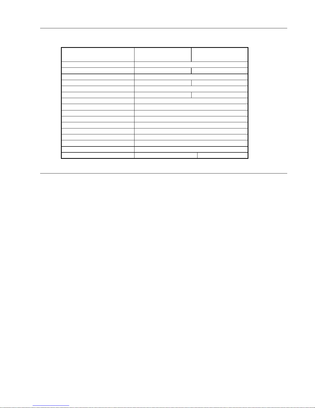
MODELS AVAILABLE
Details
Model
HW130 Modulating
Model
HW160 Modulating
Height
905
Width
520
651
Depth
325
Gas input
105.5 (95) MJ
145 (135) MJ
Gas type
Natural & (L P Gas)
Nom output
24 (21) kW
35 (32) kW
Ignition system
Electronic Ignition
Heat exchanger/burner
All copper/stainless steel
Boiler Thermostat
SIT (modulating)
Pressure relief
300kPa (3 Bar)
Expansion vessel
7 litre diaphragm (~60lt system)
Circulator
In line Centrifugal Pump
Hi limit Thermostat
99 oC
Run on timer
Timed electronic
Pressure reduction valve
1 Bar pre-set
Packed weight
50kg
60kg
STANDARD EQUIPMENT
Electronic boiler control with linking room thermostat.
Set temperature display.
Electronic ignition
Safety devices
Built in flow switch
Manual reset high limit
Built in pressure relief valve
Built to last
Double row heat exchanger made from one piece extruded finned copper tube
Stainless steel burners
Fully powder coated steel cabinet
Stainless steel flue terminal
Efficiency
Hot surface ignition
Induced draught combustion
Highly efficient stainless steel burners
Modulating input gas burner
Ease of installation
Fully plumbed ready to go, including circulating pump, expansion tank, pressure reduction valve & 1” flow
and return isolation valves.
All electrical pre wired including three pin plug.

HW130 & HW160 Modulating Boiler
5
INSTALLATION
THIS APPLIANCE MUST BE INSTALLED BY AN AUTHORISED PERSON.
Refer to boiler data plate for specifications of gas type, gas consumption, burner pressure and water pressure.
This appliance must be installed in accordance with local regulations and A.G.A. Installation Code AS5601 / AG
601.
The flow and return connections are located on the bottom of the boiler. The flow and return connections are
clearly marked and the connections are 1” BSP FI.
The Hurlcon Boiler is fitted with a built in flow switch and will not start unless full of water and the pump is
operating.
The Hurlcon Boiler incorporates a powered flue terminal suitable for outdoor installation. An indoor room sealed
model combined with co-axial flue kit for internal installation is available on request.
SAFETY RULES
For your safety – read before lighting
This appliance is equipped with an ignition device, which automatically lights the burner. Do not try to light the
burner by hand.
BEFORE OPERATING smell all around the appliance area for gas. Be sure to smell next to the floor because
some gas is heavier than air and will settle on the floor.
Safety
WHAT TO DO IF YOU SMELL GAS
Do not try to light any gas appliance.
Do not touch any electrical switch.
Turn off the gas supply at the gas meter.
Immediately call your gas supplier or licensed gas fitter.
NOTE. Some gases are heavier than air and it may be necessary to smell for leaks at floor level.
House keeping
Do not store or use flammable liquids or chemicals near this appliance.
Do not use aerosols in the vicinity of this gas appliance.
Keep this appliance free of debris.
WARNING:
Should overheating occur or the gas supply fail to shut off, turn off the manual gas control valve to the appliance.
Do not use this boiler if any part has been under water.
HW130 & HW160 Modulating Boiler
6
GUIDE TO INSTALLATION
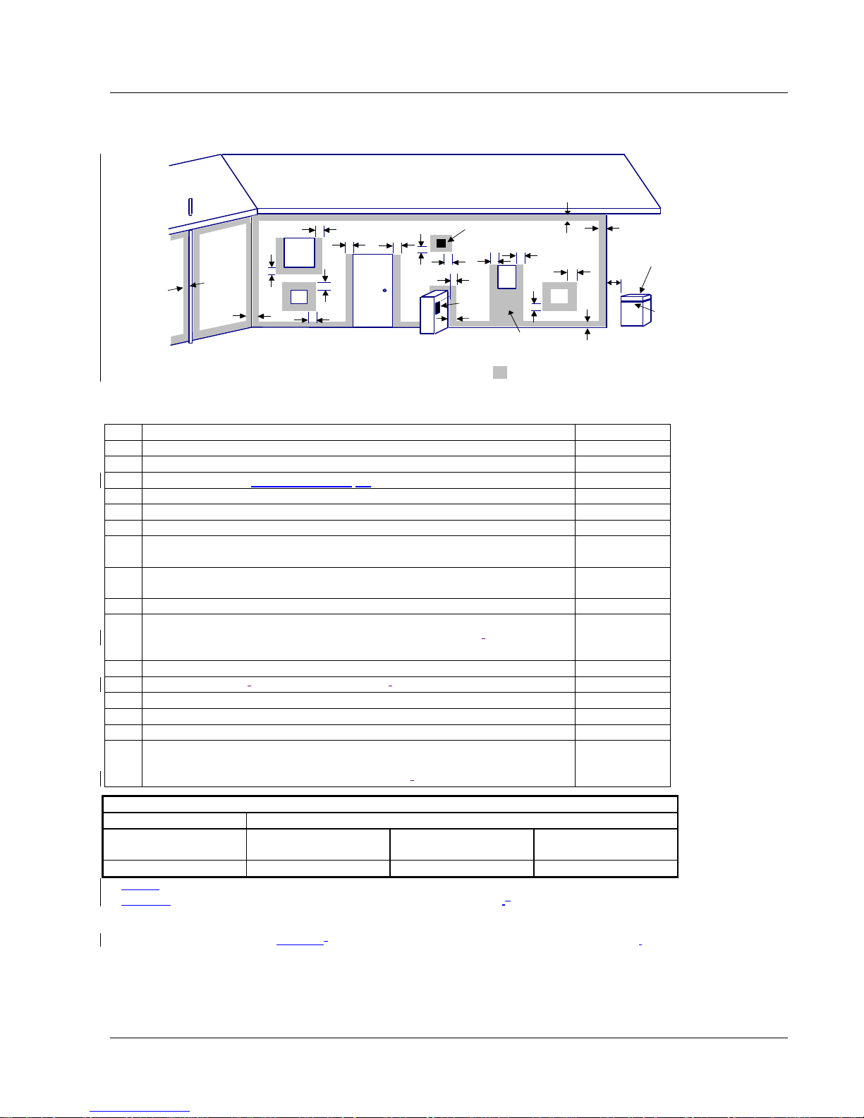
Location of Flue Terminals – An extract from AG 601
Minimum Clearances Required For Powered Flue, Balanced Flue Terminals or the Terminals of Room Sealed
Appliances.
openable
window
door
M
P
g
See note 3
T
b
d
d
e
e
See note 2
h
h
a
g
h
j
jjn
k
kcc
f
T = Flue terminal
I = Mechanical air inlet
M = Gas meter
P = Electricity meter
or fuse box
Shading indicates prohibited
areas for flue terminals
T
T
I
MIN. CLEARANCE
(mm)
A
Below eaves, balconies and other projections
Appliances up to 50 MJ/h input
200
Appliances over 50 MJ/h input
300
B
From the ground, above a balcony or other surface
300
C
From a return wall or external corner
500
D
From a gas meter (M)
1000
E
From an electricity meter or fuse box (P)
500
F
From a drain pipe or soil pipe
75
G
Horizontally from any building structure (unless appliance approved
500
for closer installation) or obstruction facing a terminal
H
From any other flue terminal, cowl, or combustion air intake
300
I
Horizontally from an openable window, door, non-mechanical air inlet,
or any other opening into a building with the exception of sub-floor
ventilation
Appliances up to 150 MJ/h input
300
Appliances over 150 MJ/h but less than 200 MJ/h input
500
Appliances over 200 MJ/h input
1500
All fan-assisted flue appliances, in direction of discharge
1500
K
From a mechanical air inlet, including a spa blower
1000
N
Vertically below an openable window, non-mechanical air inlet, or any
other
opening into a building with the exception of sub-floor ventilation
See table
CLEARANCE „n‟ (mm)
Space heaters
All other appliances
Up to 50 MJ/h
input
Up to 50 MJ/h
input
Over 50 MJ/h &
up 150 MJ/h
Over 150 MJ/h
input
150
500
1000
1500
NOTES: 1 All distances are measured to the nearest part of the terminal.
2 Prohibited area below electricity meter or fuse box extends to ground level.
3 See Clause 5.13.6.6 for restrictions on a flue terminal under a covered area.
4 See Appendix J, Figures J1(a) and J2(a), for clearances required from a flue terminal to an LP Gas
cylinder. A flue terminal is considered to be a source of ignition.
The above information is part of AG 601 FIGURE 5.3 as supplied by the AGA and is provided as an indication of
the correct clearances only. Please refer to the latest issue of AG 601.

HW130 & HW160 Modulating Boiler
7
CLEARANCES
The boiler must not be installed against any combustible surface.
Clearances must comply with AS5601 / AG 601.
Clearances from surfaces are:
Front
500mm
Both sides
50mm
Above
300mm
Below
900mm
ELECTRICAL CONNECTION
The boiler is supplied with a standard 10 amp 3 pin plug for connection to a 240V 10 amp earthed GPO. The
boiler incorporates a 240/24 VAC transformer which supplies power to the central heating thermostat only and
must not be used for any additional equipment. All equipment connected to mains power should be protected by
an RCD circuit breaker. The boiler has a 240 volt power supply for the pump, fan and gas valve control. A terminal
strip is provided for connection to the central heating thermostat.
If the supply cord is damaged, it must be replaced by the manufacturer or its service agent or a suitably qualified
person in order to avoid a hazard.
GAS CONNECTION
A ¾”BSP FI is provided for gas line connection. An approved manual shut off valve must be installed in the gas
fitting line before the boiler so that the gas can be turned off and the boiler removed for servicing if required. The
gas shut off valve should be sized the same as the gas fitting line to prevent excessive pressure drop in the gas
pipe.
The gas fitting line should be installed by an authorised person and comply with local regulations and A.G.A. code
AGS5601. The gas line from the meter will usually be of a larger size than the gas inlet connection. Therefore a
reduction to the boiler connection fitting will be necessary. The reduction should be as close to the boiler as
possible.
Before using the boiler, test all connections for gas leaks using soapy water.
The boiler gas valve has a built in pressure regulator with a ⅛” pressure test point provided. On starting the boiler,
a manometer must be used and burner pressure checked against the boiler data plate. The gas valve regulator
may need adjustment to correct manifold pressure. Incorrect burner pressure may void warranty.
HW130 & HW160 Modulating Boiler
8
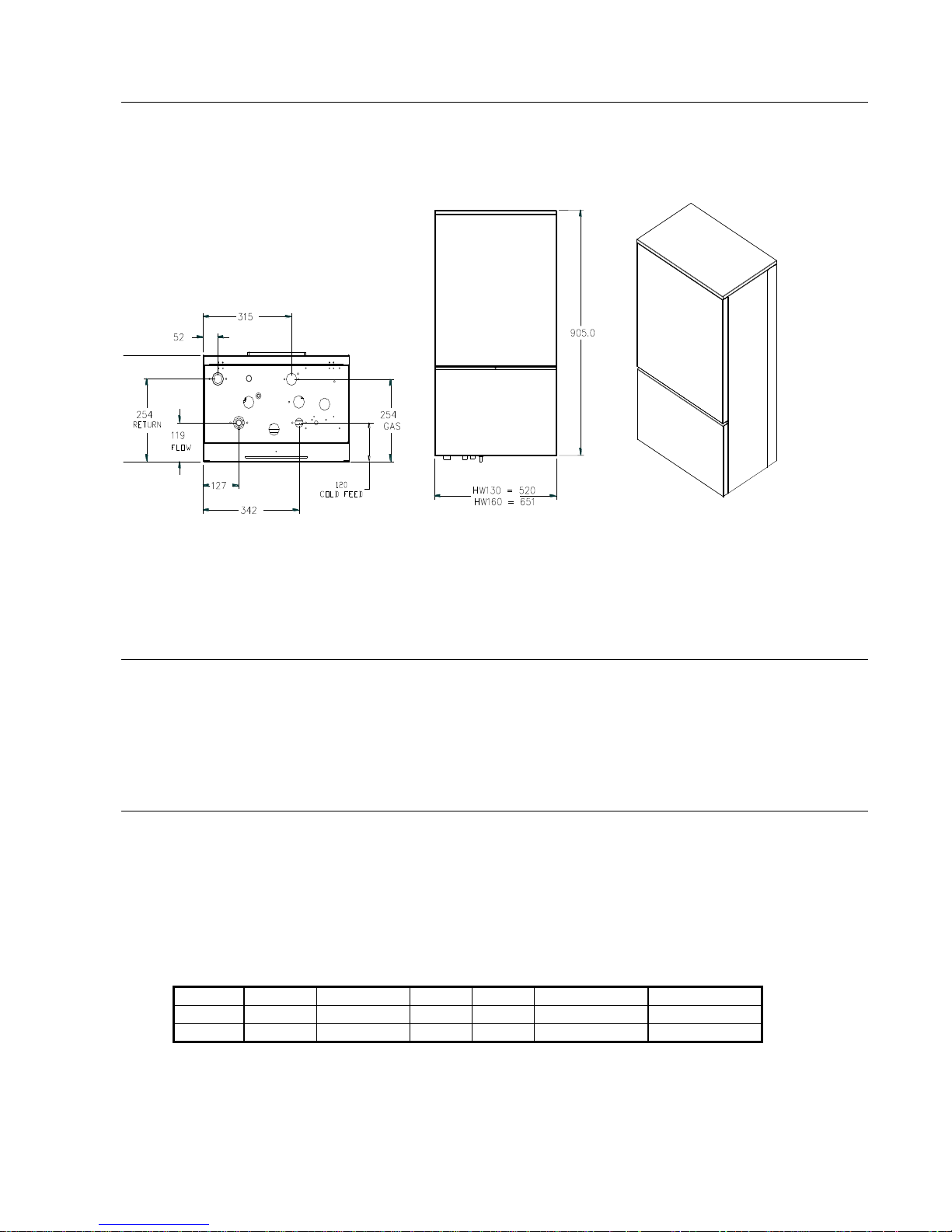
BOILER DIMENSIONS
INDOOR INSTALLATION
This boiler is designed for outdoor use only. If the HW130 - 160 Boiler is to be installed indoors, a dedicated
indoor model with special flue kit is available.
HEATING PIPE SIZE & LAYOUT
The flow & return connection sizes of 1”BSP on the boiler are not necessarily the correct pipe sizes for the
heating system. It is important that the pipe sizes are correctly calculated before installation.
Hurlcon recommend a two pipe system with the pipes sized according to the flow requirements and length
of runs with a maximum water velocity of 1.5 M/s.
Reference The Institute of Plumbing Australia. - “SELECTION & SIZING OF COPPER TUBES FOR
PIPING SYSTEMS”.
Nominal flow capacities
Model
Output
Flow rates
DT
pd
min Pipe dia
F & R length
130
24 kW
0.38 l/s
15 oC
8 kPa
20 mm
6.0 m
160
35 kW
0.53 l/s
15 oC
14 kPa
25 mm
4.5 m
 Loading...