

Page 1

Lathe Programming Guide
I. Getting Started.
Steps to make sure your lathe is configured properly.
II. Two Axis Lathe Samples
Machines Covered
TM6, TM8, TM10, TM12, TM18
TMX8, TMX10
III. Live Tool Lathe Samples
Machines Covered
TMM8, TMM10
IV. Live Tool Y Axis Lathe Samples
Machines Covered
TMX8MY, TMX8MYS, TMX10MY, TMX10MYS
All live tool lathes that are an “i” series machine will use the same examples.
All examples are done programming in software version 09.02.68
Please read this document until a stop for your machine type is reached.
This document was designed to be used as a work book, do not jump ahead!
This document was developed by Hurco Applications in Indianapolis Indiana by Hurco USA.
THIS DOCUMENT IS STILL IN THE TESTING, THIS DOCUMENT MAY NOT BE EXACT OR COMPLETE AT THIS
TIME, PLEASE CALL HURCO APPLICATIONS FOR ADDITIONAL SUPPORT.
Page 2

I. Getting Started
Make sure the software version on the machine is on this software or a
more current version than 09.02.68.
Check the first two digits to make sure it is larger than 09
Check the second set of digits to make sure it is larger than 02
Check the last set of digits to make sure it is larger than 68
Page 3
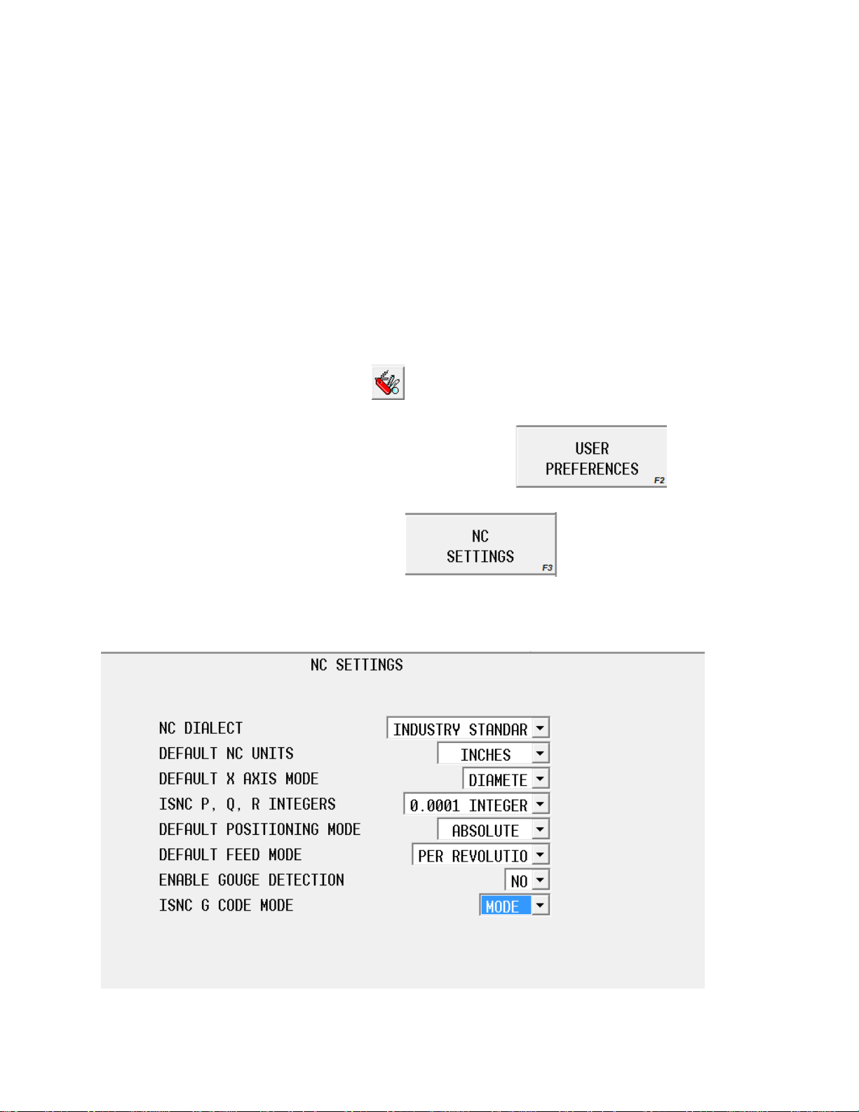
The next step is to make sure the NC setting have been
properly set.
Press the AUX/Menu button on the control.
This button is located next to the Input button on the control. It will be one of the large
oval shaped buttons.
Press the utilities key on the touch screen.
Press the user preferences soft key
Press the NC Setting key
This control should display this screen.
Page 4

Set all the settings as displayed above. The only setting
that may change is the ISNC G Code Mode. (see next page)
There are Two settings for G code interpertation.
The easiest way to think about these two modes is to imagine they are dialects, some of the
codes will mean different things, however all the functionallity exist in both modes, you may just need
to use a different code.
STOP!
Some codes are only available in certain modes. The mode of ISNC G-code will determine how
to program the machine.
Mode A is an older style of code and may not have all the functionality that Mode B will
contain. Mode A’s purpose is to add flexability. Mode A may allow programs from an older
control that is not a Hurco control to run on a hurco control will little to no modification.
Mode B is the Prefered way to program a Hurco Turning
Center!
ALL EXAMPLES WILL BE IN MODE B!
Page 5

Mode A
Mode B
G50
Max RPM
G92
Max RPM
G98
Per Min Feed
G94
Per Min Feed
G99
Per Rev Feed
G95
Per Rev Feed
No Code
G98
Return to Initial Level
No Code
G99
Return to R point Level
G94
End Face Turning Cycle
G79
End Face Turning Cycle
G92
Thread Cutting Cycle
G78
Thread Cutting Cycle
No Code
X,Y,Z Coordinates Abs
G90
Absolute Programming
No Code
U,V,W Coordinates Inc
G91
Incremental
Programming
G90
Outer/Inner Cutting
Cycle
G77
Outer/Inner Cutting
Cycle
G32
Thread Cutting
G33
Thread Cutting
Most codes will retain the same functionallity.
These codes Containt the same functionality between modes, however may still require different
parameters.
G00, G01, G02, G03, G04, G06, G07, G08, G09, G10, G11, G17, G18, G19, G20, G21, G28, G40, G41, G42,
G53, G54-G59, G54.1, G61, G64, G65, G66, G67, G70, G71, G72, G73, G74, G75, G76, G80, G81, G82,
G83, G84, G85, G86, G87, G88, G89, G93, G96, G97.
This table will show the main differences
The table above can be used as a reference guide to change
codes to alter an existing program.
Page 6

II. Two Axis Lathe Programming Guide
Tools
1. OD turning tool
2. OD threading tool
3. ½ inch drill
4. ID turning tool
5. 1/8 cutoff/grooving tool
To start a Lathe Program begin with a safe startup line.
%
O1234(SAFE STARTUP LINE EXAMPLE)
G20 G40 G80 G90
G28 U0. W0. (SENDS TURRET HOME)
From This point call up a tool and set the max rpm and turn on the spindle.
T0101 (CALL TOOL ONE OFFSET ONE)
G92 S1000 (MAX RPM 1000RPM)
G97 M3 S500 (TURN THE SPINDLE ON AT 500 RPM)
Now we are ready to call up a work offset and command motion
G54
G0 G95 Z.25
From this point on we are able to begin programming features
From this point on most likely the next operation would be facing the part. We will leave
stock to take off later with a finish cycle.
Note: you must leave stock with a roughing cycle.
Tip: the position right before a canned cycle should be a safe position or
rapid position.
Page 7
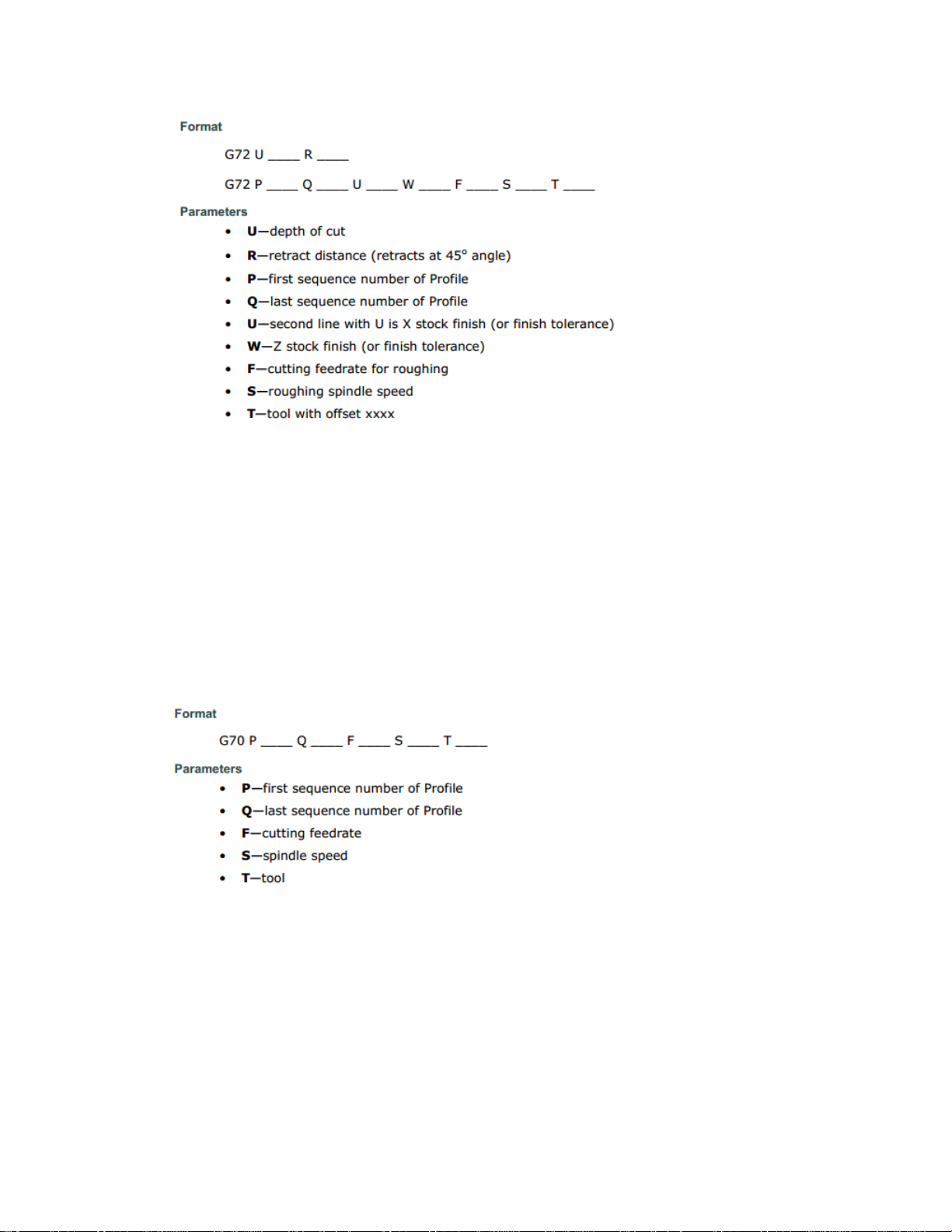
X2.25
G96 G1X2.1 F.004 (CONSTANT SURFACE SPEED)
G72 U.1 R.1 (U is depth of cut R is retract distance)
G72 P1 Q2 U0.005 W0.005 F.002 S1000 T0101
N1 G1 X2.0 Z0.
X-.04
N2 Z.05
G0 X2.25 Z.25 (RETURN TO SAFE POSITION)
Since the face is now roughed we can come back in with a finish pass
G70 P1 Q2 F.002 S1000
X2.25 Z.25 (RETURN TO SAFE POSITION)
In this example the profile was used from the roughing cycle.
Next step is to cut a profile. The profile for this example will be a basic step cylinder.
Page 8
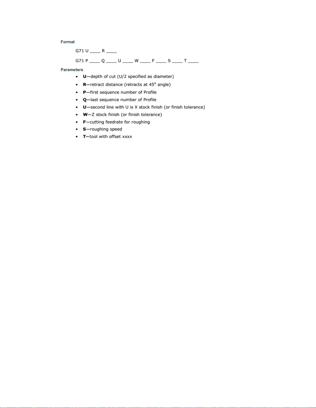
G71 U.1 R.1
G71 P3 Q4 U.005 W.002 F.005 S1000
N3 G1 Z.05 X.95
Z0.
X1.Z-.025
Z-.5
X1.2
X1.25 Z-.55
Z-1.
G2 X1.75 Z-1.25 R.25
G1 X1.95
X2. Z-1.3
N4X2.05
X2.25 Z.25 (RETURN TO SAFE POSITION)
Now the profile is roughed finishing can be done with one line of code.
G70 P3 Q4 F.002 S1000
X2.25 Z.25 (RETURN TO SAFE POSITION)
M5 (STOP SPINDLE)
Page 9
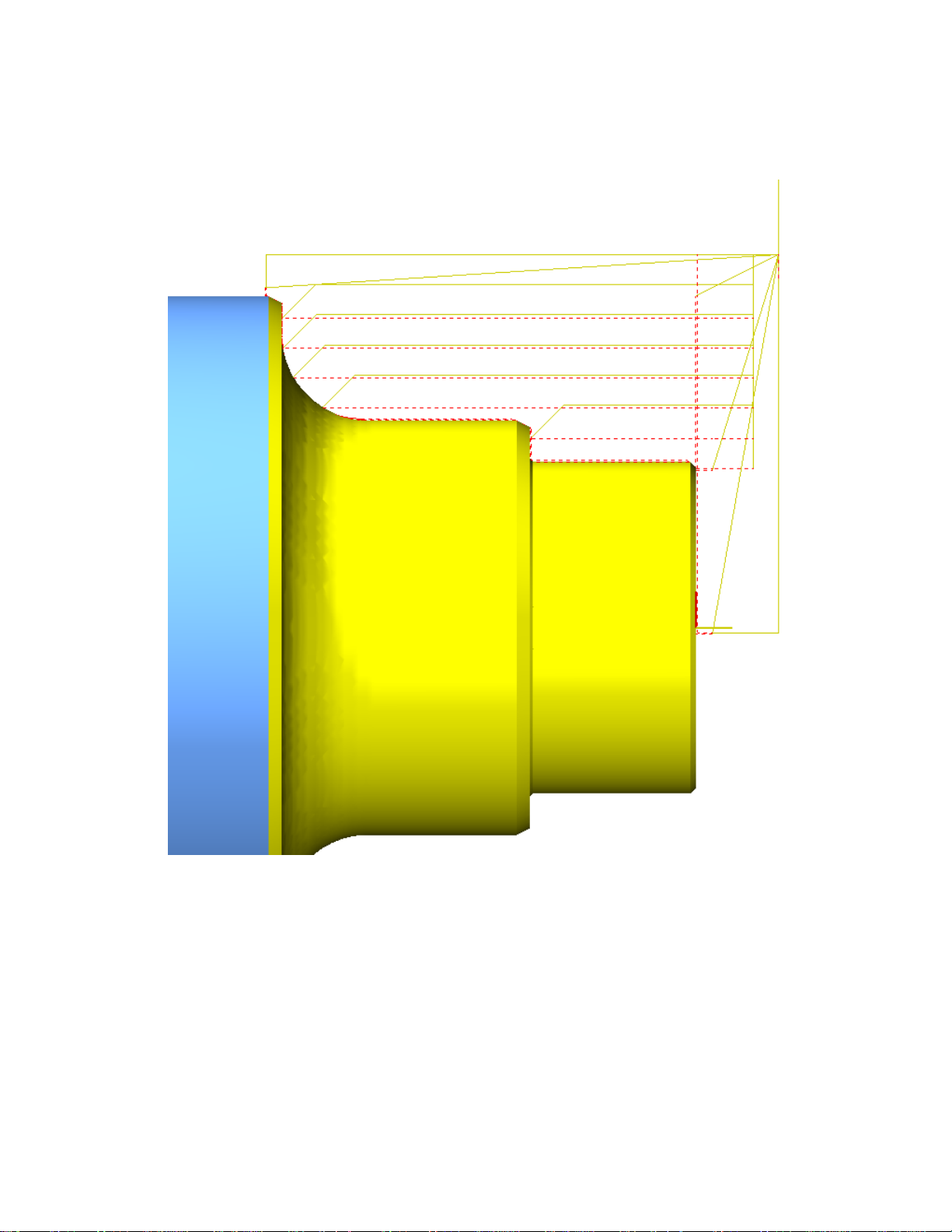
The code above should display an image similar to this in the graphics screen.
Page 10
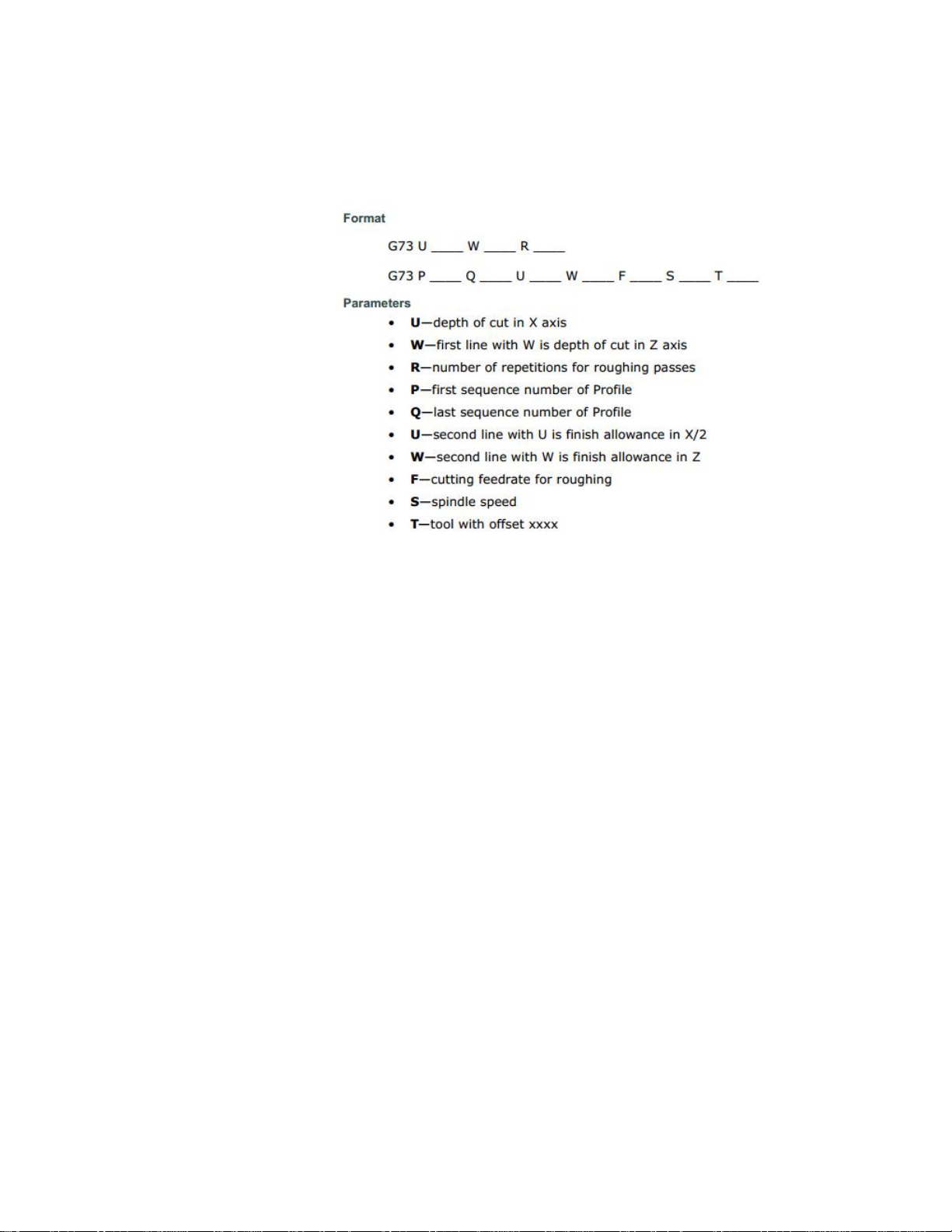
Note: G73 can also be used to rough a profile, or to do multiple finish passes to
step down a profile.
Tool change
Before the turret is indexed to the next tool it should be at the home position.
G28 U0. W0.
Now the turret can index and setup the speed for the next tool and move to position.
T0202
G92 S1000
G97 M3 S500
G54
G0 G95 Z.25
X2.25
From this point an OD thread will be cut.
Page 11

There are 3 cycles for threading in Mode B.
G33
Long Hand
G33 X___ Z___ P___(Start angle) F___
G76
Multiple Threading Cycle
G76 PXXXXXX Q___ R___
G76 X(U)___ Z(W)___ R___ Q___ F___
G78
Threading Cycle (box cycle)
G78 X___ Z___ R____(taper) F____
For this example G76 will be used
G76 P XX XX XX Q___ R___
The first two XX - number of finish passes 01-99
The second two XX – How many revs for a lead out 00-99
The final two XX – Angle of the tool tip (60 for 60 degree V)
Q- depth of cut
R – Finish Allowance
G76 X(u)___ Z(w)___ R___ P___ Q___ F___
X – Minor Diameter
Z – End position
R – Start radius minus end radius (taper)
P – Thread Height (major – minor)
Q – Depth for first pass
F – Thread lead
Page 12
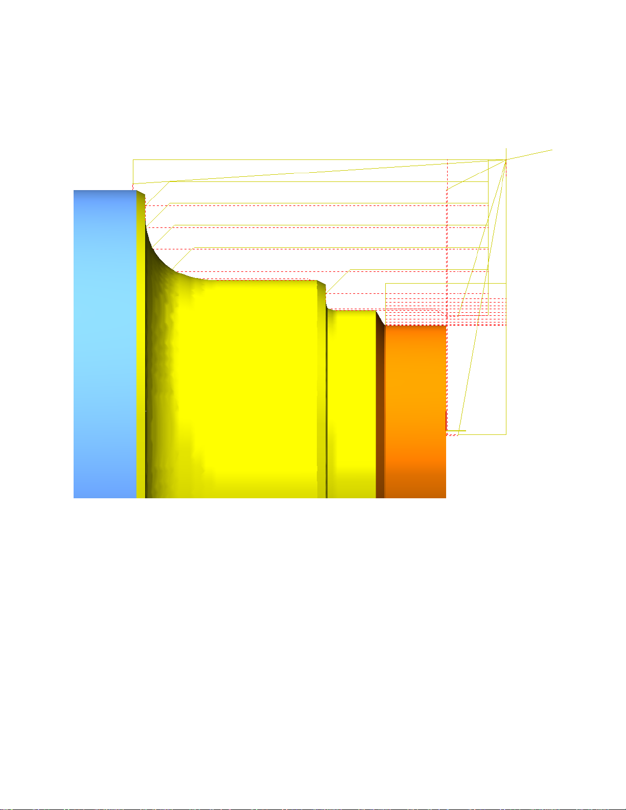
G76 P010060 Q.01 R.002
G76 X.875 Z-.25 R0 P.125 Q.015 F.076
X2.25 Z.25 (RETURN TO SAFE POSITION)
M5 (STOP SPINDLE)
At this point the part should resemble this in the graphics.
Now that the threading has finished the machine is ready to call
up another tool. The turret must be sent to the home position.
G28 U0. W0. (SENDS TURRET HOME)
Page 13

The next step is going to be drilling.
The drill must be positioned
T0303
G92 S1000
G97 M3 S700
G54
G0 G95 Z.25
X0.
There are several drilling cycles
G81 X___ Z___ F___ S___ (standard drill cycle)
G82 X___ Z___ P___ F___ S___ (dwell drill cycle)
G83 X___ Z___ P___ Q___ F___ S___ (peck drill cycle)
G83.1 X___ Z___ P___ Q___ F___ S___ (chip breaker)
X - X position
Z - Depth
F - Feed
S - Speed (RPM)
P - Dwell at the bottom of the hole
Q - Peck depth
G83 X0. Z-1.5 P1. Q.1 F.005 S700
G80 (CANCELS CANNED CYCLE)
M5 (STOP SPINDLE)
The drill needs to be sent home.
G28 U0. W0. (SENDS TURRET HOME)
Page 14
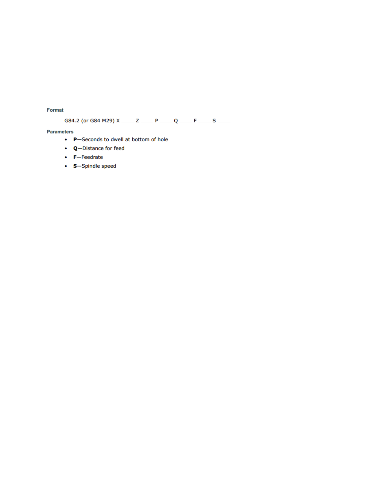
There is also Rigid tapping available. This is not in the
sample code, however here is the information for the canned
cycle.
Here is an example line of code for rigid tapping
M29
G84 X0. Z-.5 P1. Q.25 F.07692 S250
Q is Peck depth.
The next process is boring.
This follows the same principles as OD turning and facing.
T0404
G92 S1000
G97 M3 S500
G54
G0 G95 Z.25
X.5
G96
G71 P5 Q6 U.005 W.002 F.005 S1000
N5 G1 X.85 Z.05
Z0.
X.75 Z-.05
Z-1.
N6 X.5
G0 Z.25 X.5
G70 P5 Q6 F.002 S1000
G0 Z.25 X.5
Page 15

M5 (STOP SPINDLE)
Once those operations are completed the tool should be sent
home for a tool change.
G28 U0. W0. (SENDS TURRET HOME)
Now the grooving tool should be called up in the program, and
we can position to a safe position
T0505
G92 S1000
G97 M3 S500
G54
G0 G95 Z-.3
X2.25
Page 16

There is no canned cycle for grooving; everything must be
programmed point to point.
X1.1 Z-.3
G96
G1 X.865 F.005
G0 X1.1
Z-.25
G1 X1. F.002
Z-.275
G3 X.95 Z-.3 R.025
G1 X.865
G0 X1.1
Z-.35
G1 X1. F.002
Z-.325
G2 X.95 Z-.3 R.025
G1 X.865
G0 X2.25
M5 (STOP SPINDLE) (DO NOT USE THIS LINE IF THE MACHINE IS A 2 AXIS LATHE. A SPINDLE STOP
IS ONLY NEEDED IF ANOTHER TOOL WERE TO BE CALLED.)
If the machine has live tool capabilities please skip cutoff block
Live tool operations will be programmed before cutoff.
Page 17
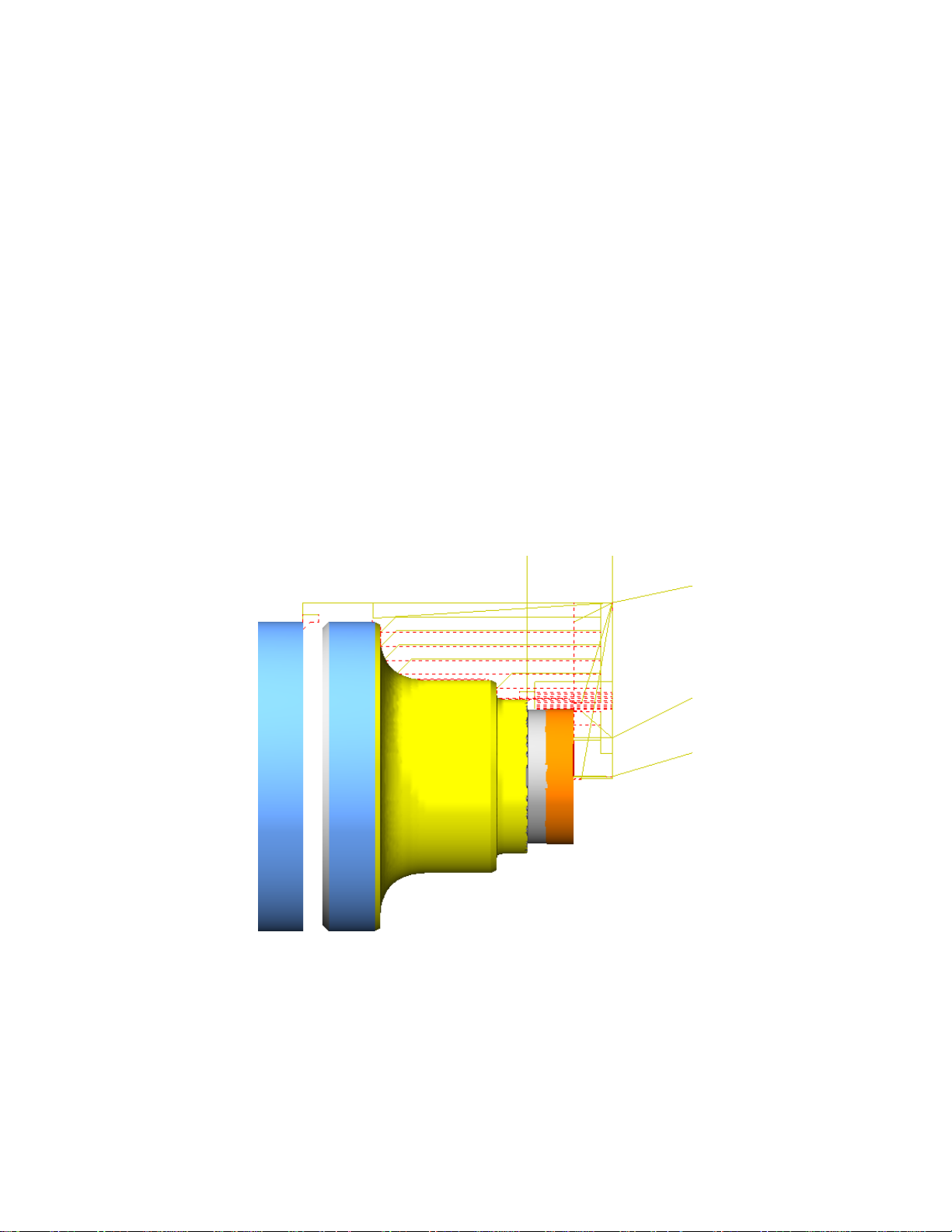
Cutoff
Omit the 4 lines below (green) for two axis example; these 4 lines are only for reference for live
tool examples.
T0505
G92 S1000
G97 M3 S500
G54
Z-1.75
X2.1
G1 X1.85 F.003
G0 X2.1
Z-1.65
G1 X2.
Z-1.7
X1.9 Z-1.75
X-.04
X2.25
M5 (STOP SPINDLE)
G28 U0. W0.
Page 18

Two axis sample program
%
O1234(TWO AXIS SAMPLE)
G20 G40 G80 G90
G28 U0. W0. (SENDS TURRET HOME)
T0101 (CALL TOOL ONE OFFSET ONE)
G92 S1000 (MAX RPM 1000RPM)
G97 M3 S500 (TURN THE SPINDLE ON AT 500 RPM)
G54
G0 G95 Z.25
X2.25
G96 G1X2.1 F.004
G72 U.1 R.1 (U IS DEPTH OF CUT R IS RETRACT DISTANCE)
G72 P1 Q2 U0.005 W0.005 F.002 S1000 T0101
N1 G1 X2.0 Z0.
X-.04
N2 Z.05
G0 X2.25 Z.25 (RETURN TO SAFE POSITION)
G70 P1 Q2 F.002 S1000
X2.25 Z.25 (RETURN TO SAFE POSITION)
G71 U.1 R.1
G71 P3 Q4 U.005 W.002 F.005 S1000
N3 G1 Z.05 X.95
Z0.
X1.Z-.025
Z-.5
X1.2
X1.25 Z-.55
Z-1.
G2 X1.75 Z-1.25 R.25
G1 X1.95
X2. Z-1.3
N4X2.05
X2.25 Z.25 (RETURN TO SAFE POSITION)
G70 P3 Q4 F.002 S1000
X2.25 Z.25 (RETURN TO SAFE POSITION)
M5 (STOP SPINDLE)
G28 U0. W0. (SENDS TURRET HOME)
T0202
G92 S1000
G97 M3 S500
G54
G0 G95 Z.25
Page 19

X2.25
G76 P010060 Q.01 R.002
G76 X.875 Z-.25 R0 P.125 Q.015 F.076
X2.25 Z.25 (RETURN TO SAFE POSITION)
G28 U0. W0. (SENDS TURRET HOME)
M5 (STOP SPINDLE)
T0303
G92 S1000
G97 M3 S700
G54
G0 G95 Z.25
X0.
G83 X0. Z-1.5 P1. Q.1 F.005 S700
G80 (CANCELS CANNED CYCLE)
G28 U0. W0. (SENDS TURRET HOME)
M5 (STOP SPINDLE)
T0404
G92 S1000
G97 M3 S500
G54
G0 G95 Z.25
X.5
G96
G71 P5 Q6 U.005 W.002 F.005 S1000
N5 G1 X.85 Z.05
Z0.
X.75 Z-.05
Z-1.
N6 X.5
G0 Z.25 X.5
G70 P5 Q6 F.002 S1000
G0 Z.25 X.5
G28 U0. W0. (SENDS TURRET HOME)
M5 (STOP SPINDLE)
T0505
G92 S1000
G97 M3 S500
G54
G0 G95 Z-.3
X2.25
X1.1 Z-.3
G96
G1 X.865 F.005
G0 X1.1
Page 20

Z-.25
G1 X1. F.002
Z-.275
G3 X.95 Z-.3 R.025
G1 X.865
G0 X1.1
Z-.35
G1 X1. F.002
Z-.325
G2 X.95 Z-.3 R.025
G1 X.865
G0 X2.25
Z-1.75
X2.1
G1 X1.85 F.003
G0 X2.1
Z-1.65
G1 X2.
Z-1.7
X1.9 Z-1.75
X-.04
G0X2.25
M5 (STOP SPINDLE)
G28 U0. W0. (SENDS TURRET HOME)
M30
Page 21

STOP!
If the machine to be programmed is one of the
following machines all the post information
needed is above.
TM6
TM8
TM10
TM12
TM18
TM18L
TMX8
TMX10
This includes any machine above with the letter
“i” afterwards
Page 22

III. Live Tool Examples
Tools
6. Live Drill .201
7. End mill .25
8. End mill .25
When dealing with Live Tool machines there must be an
understanding of these simple codes and how to utilize them.
First off there are two machine modes, milling and turning.
M130 – Turning mode
M131 – Milling Mode
All these codes establish are what spindle will be turning,
as well as which spindle will everything be calculated from;
such as Feed Per Revolution. Turning mode is main spindle (or
sub on MYS machines). Milling mode is Live tools.
There are also 3 axis Maps that apply to the TMM
machines.
G101 – Milling on the face of the part
G102 – Milling on the diameter of the part
G109 – Turning or positional drilling using the c axis
When Using a Milling Map C axis positions cannot be used! Those maps do not
contain a C axis, everything is interpolated from X and Y coordinates.
Page 23
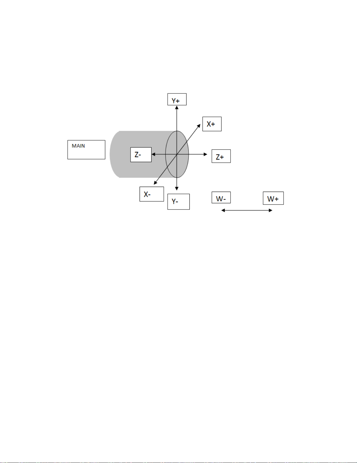
G101 AXIS MAP DIAGRAM
Notice that the axes are the same layout as turning with
the addition of the Y axis.
This map will always use the milling mode (M131)
Again there is no C axis in this map!
The intended purpose of this map is to handle all polar
interpolation internally from X and Y positions. This map is
suitable for all milling and drilling operations on the face of the
part, however drilling can be done using C axis positions in the
G109 map.
Page 24
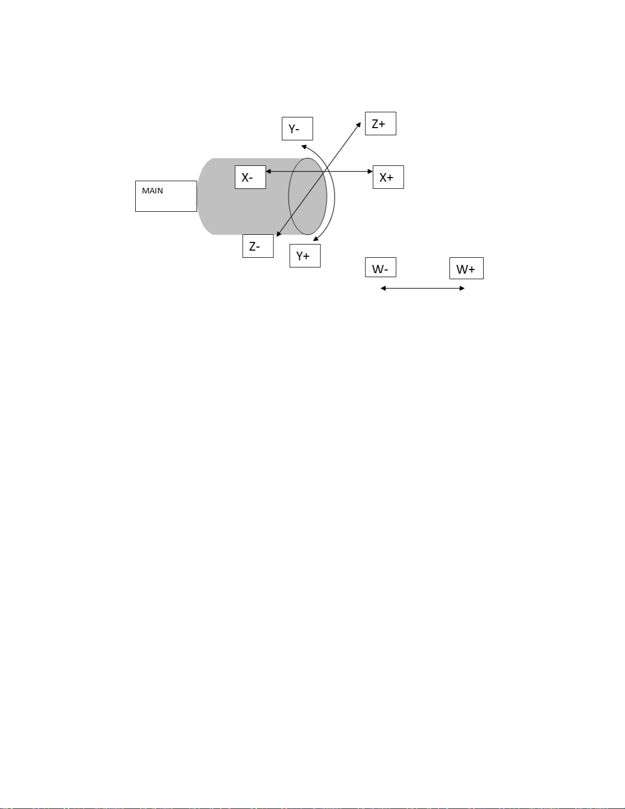
G102 AXIS MAP DIAGRAM
This map will swap the X and Z axis. Notice the Y axis is
wrapped around the diameter of the bar to be programmed,
and that Z0 is on the diameter of the bar.
This map will need to be used in conjunction with an
additional code to establish a working diameter.
G25 Q (whatever the working diameter is)
This map is suitable for all milling and drilling on the outside of
the part, however drilling can be done on the diameter of the
part using C positions if desired in the G109 map.
No C axis positions are allowed in this map!
Page 25
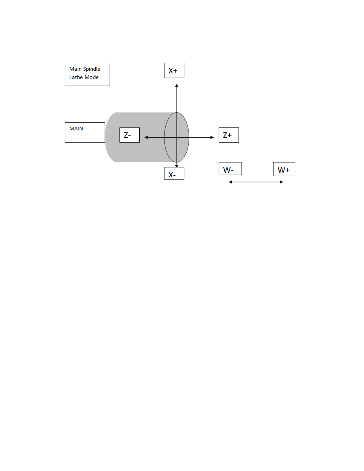
G109 AXIS MAP DIAGRAM
This axis map uses standard axes for a lathe and is suitable
for all turning operations.
The typical mode for this map is the Turning Mode (M130)
This map also can be used in conjunction with the Milling
Mode (M131) for drilling holes with X, Z, and C positions.
Page 26

Utilizing the G109 map properly for drilling
First call the proper tool and change modes.
T0606
G109 (TURNING MAP)
M131 (MILLING MODE)
G7 (RADIUS PROGRAMMING)
G97 M33 S1500 (TURN SPINDLE ON AT FIXED RPM)
G54
Now that the proper tool has been called up in the proper
mode an approach can be designated.
G0 Z.25 C0.
X.75
Z-.75
Now a canned cycle can be executed.
G98 G81 X.75 Z-1.625 F.002 S1500 (DRILLING CANNED CYCLES)
C45.
C90.
C135.
C180.
C225.
C270.
C315.
G80 (CANCEL CANNED CYCLE)
G00 X2.25 Z.25
G8 (DIAMETER PROGRAMMING)
M130
M35 (STOP LIVE TOOL)
In this mode all canned cycles can be executed and are
available.
Page 27

After the holes are drilled the turret should be positioned
to index the turret
G28 U0. W0. (SENDS TURRET HOME)
It is important to place a G7 at the beginning of any live
tool operation to program in radius mode, if this isn’t done all x
number will need to be doubled.
It is equally important to return to G8 after the features
are cut that way if a turning process follows milling the turning
can be programmed in diameter.
When programming a lathe it is also important to program
in Feed Per Rev if possible. The advantage to this is the spindle
will give feedback as to what the RPM is and calculate the IPM
from there. The biggest advantage to this is if a spindle were to
stall, the machine will recognize that the spindle has slowed or
stopped and adjust the feed accordingly. On milling tools this is
not acceptable because they normally have multiple flutes,
however for all drilling, tapping, and turning all feed rates
should be in Feed Per Rev.
The next step will be to mill to flats on the side of the part
using cutter comp.
Page 28

The next tool will be loaded and used to mill in the G101
map.
The G109 mode will be used to execute an approach.
Programming in the way allows the C axis to be positioned
without forcing the tool to travel through the center of the
part.
T0707
G109
M131
G97 M33 S1500
G54
G0 Z.25 C0.
X2.5
Now that the approach move has been programed cutting
motion with the proper map can be executed.
G101
G7
G94
X-.5 Y1.25
Z-1.625
G1 G41 Y.95 F10.
X.5
G40 Y1.25
G0 Z.25
G109
X2.5
C180.
G101
X.5 Y-1.25
Z-1.625
G1 G41 Y-.95 F10.
X-.5
G40 Y-1.25
G0 Z.25
G109
Page 29
M130
G95
G8
M35 (STOP LIVE TOOL)
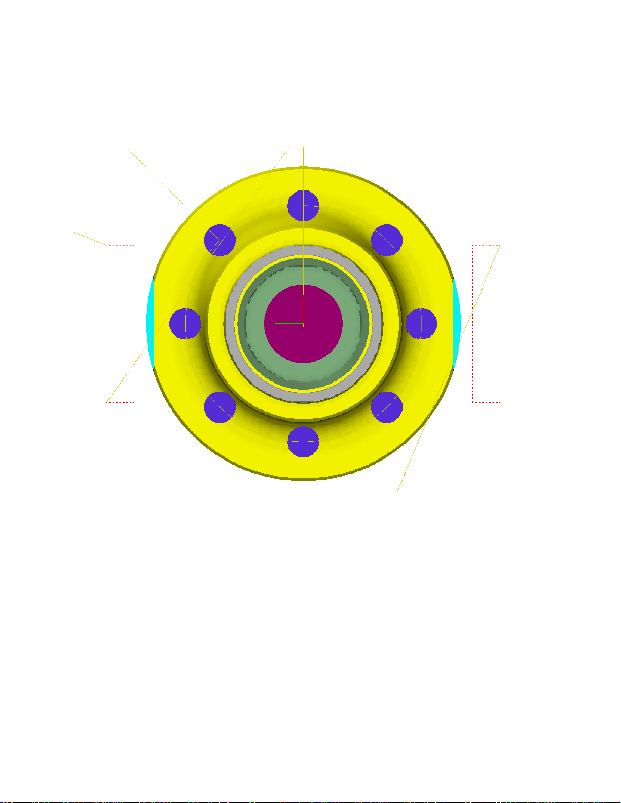
At this point your part should resemble the picture above.
Now the turret should be indexed so that the radial tool can cut
on the surface of the bar.
G28 U0. W0. (SENDS TURRET HOME)
The next and final step for programming a live tool lathe
will be to program machining on the diameter of the part. The
tool will need to be indexed to and positioned.
Page 30

T0808
G102
G7
G25 Q2.
M131
G97 M33 S1500
G54
G94
G0 X-1.25
Z.25
The diameter established is a 2 inch diameter; this is
established with the G25 Q2. line. If we multiply the diameter
by 3.1415 we get 6.2831. That means 0.000 will be at 0
degrees, and 6.2831 will be 360 degrees. A CAD/CAM system
will generate the proper values; in this example the values are
given. This axis map must have a Q value greater than .1, Q0. Is
not acceptable.
This example is done with point to point data
Y-.3927
G01 Z-.125 F10.
Y.3927
G0 Z.25
Y2.7488
G1 Z-.125 F10.
Y3.5342
G0 Z.25
From here all that is needed is to restore the settings so
that we could return to a turning mode.
G109
Page 31
M130
G95
G8 (DIAMETER PROGRAMMING)
M35 (STOP LIVE TOOL)
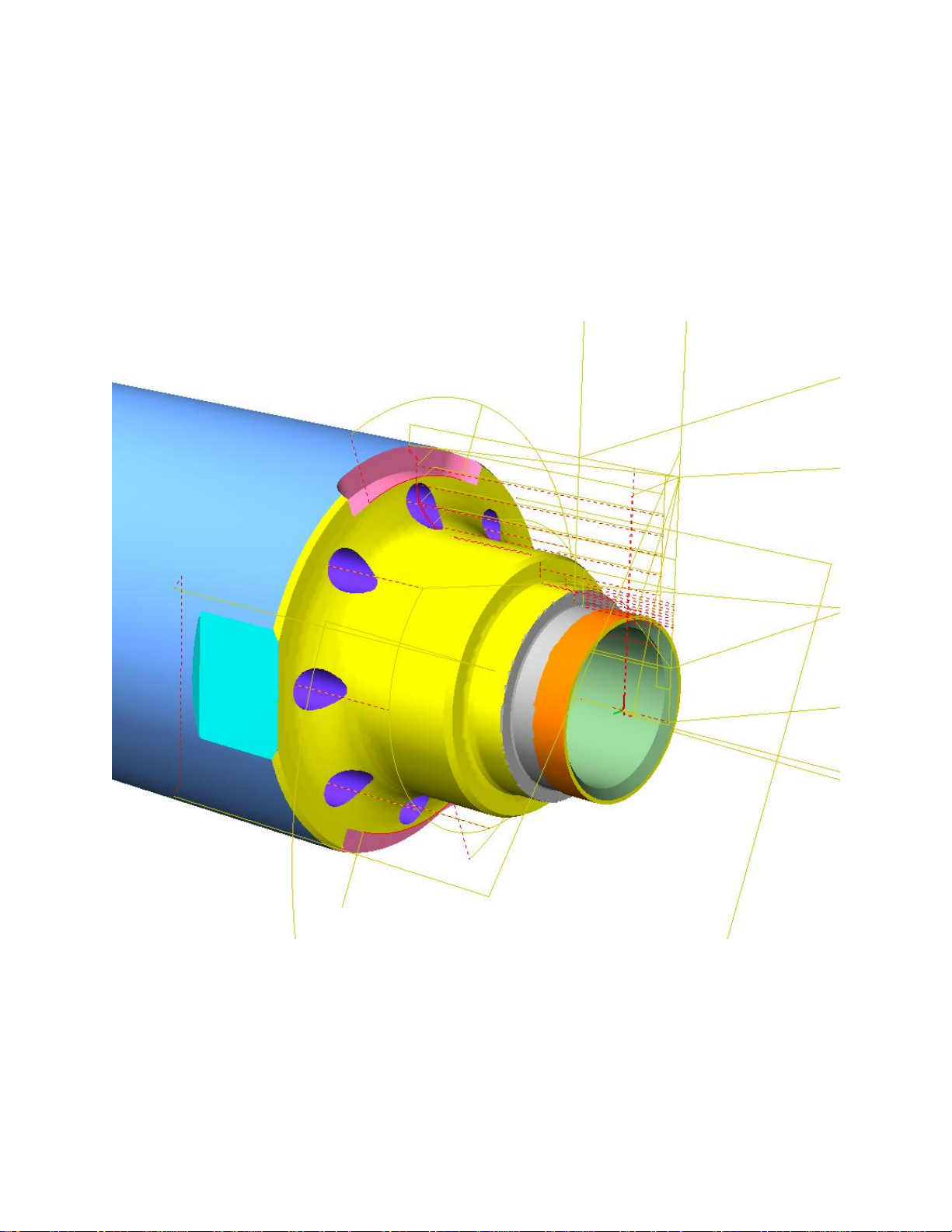
At this point the part should look like this
After every live tool operation, before a tool change the map
and mode will need to be switch back to Turning
G109
M130
Page 32

%
O1234(SAFE STARTUP LINE EXAMPLE)
G20 G40 G80 G90
G28 U0. W0. (SENDS TURRET HOME)
T0101 (CALL TOOL ONE OFFSET ONE)
G92 S1000 (MAX RPM 1000RPM)
G97 M3 S500 (TURN THE SPINDLE ON AT 500 RPM)
G54
G0 G95 Z.25
X2.25
G96 G1X2.1 F.004
G72 U.1 R.1 (U IS DEPTH OF CUT R IS RETRACT DISTANCE)
G72 P1 Q2 U0.005 W0.005 F.002 S1000 T0101
N1 G1 X2.0 Z0.
X-.04
N2 Z.05
G0 X2.25 Z.25 (RETURN TO SAFE POSITION)
G70 P1 Q2 F.002 S1000
X2.25 Z.25 (RETURN TO SAFE POSITION)
G71 U.1 R.1
G71 P3 Q4 U.005 W.002 F.005 S1000
N3 G1 Z.05 X.95
Z0.
X1.Z-.025
Z-.5
X1.2
X1.25 Z-.55
Z-1.
G2 X1.75 Z-1.25 R.25
G1 X1.95
X2. Z-1.3
N4X2.05
X2.25 Z.25 (RETURN TO SAFE POSITION)
G70 P3 Q4 F.002 S1000
X2.25 Z.25 (RETURN TO SAFE POSITION)
M5 (STOP SPINDLE)
G28 U0. W0.
T0202
G92 S1000
G97 M3 S500
G54
G0 G95 Z.25
Page 33

X2.25
G76 P010060 Q.01 R.002
G76 X.875 Z-.25 R0 P.125 Q.015 F.076
X2.25 Z.25 (RETURN TO SAFE POSITION)
G28 U0. W0.
M5 (STOP SPINDLE)
T0303
G92 S1000
G97 M3 S700
G54
G0 G95 Z.25
X0.
G83 X0. Z-1.5 P1. Q.1 F.005 S700
G80 (CANCELS CANNED CYCLE)
G28 U0. W0.
M5 (STOP SPINDLE)
T0404
G92 S1000
G97 M3 S500
G54
G0 G95 Z.25
X.5
G96
G71 P5 Q6 U.005 W.002 F.005 S1000
N5 G1 X.85 Z.05
Z0.
X.75 Z-.05
Z-1.
N6 X.5
G0 Z.25 X.5
G70 P5 Q6 F.002 S1000
G0 Z.25 X.5
G28 U0. W0.
M5 (STOP SPINDLE)
T0505
G92 S1000
G97 M3 S500
G54
G0 G95 Z-.3
X2.25
X1.1 Z-.3
G96
G1 X.865 F.005
G0 X1.1
Page 34

Z-.25
G1 X1. F.002
Z-.275
G3 X.95 Z-.3 R.025
G1 X.865
G0 X1.1
Z-.35
G1 X1. F.002
Z-.325
G2 X.95 Z-.3 R.025
G1 X.865
G0 X2.25
M5 (STOP SPINDLE)
G28 U0. W0.
T0606
G109 (TURNING MAP)
M131 (MILLING MODE)
G7 (RADIUS PROGRAMMING)
G97 M33 S1500 (TURN SPINDLE ON AT FIXED RPM)
G54
G0 Z.25 C0.
X.75
Z-.75
G98 G81 X.75 Z-1.625 F.002 S1500
C45.
C90.
C135.
C180.
C225.
C270.
C315.
G80
G00 X2.25 Z.25
G8 (DIAMETER PROGRAMMING)
M130
M35 (STOP LIVE TOOL)
G28 U0. W0.
T0707
G109
M131
G97 M33 S1500
G54
G0 Z.25 C0.
X2.5
Page 35

G101
G7
G94
X-.5 Y1.25
Z-1.625
G1 G42 Y.95 F10.
X.5
G40 Y1.25
G0 Z.25
G109
X2.5
C180.
G101
X.5 Y-1.25
Z-1.625
G1 G42 Y-.95 F10.
X-.5
G40 Y-1.25
G0 Z.25
G109
M130
G95
G8
M35 (STOP LIVE TOOL)
G28 U0. W0.
T0808
G102
G7
G25 Q2.
M131
G97 M33 S1500
G54
G94
G0 X-1.25
Z.25
Y-.3927
G01 Z-.125 F10.
Y.3927
G0 Z.25
Y2.7488
G1 Z-.125 F10.
Y3.5342
G0 Z.25
G109
Page 36

M130
G95
G8 (DIAMETER PROGRAMMING)
M35 (STOP LIVE TOOL)
G28 U0. W0.
T0505
G92 S1000
G97 M3 S500
G54
Z-1.75
X2.1
G1 X1.85 F.003
G0 X2.1
Z-1.65
G1 X2.
Z-1.7
X1.9 Z-1.75
X-.04
X2.25
M5 (STOP SPINDLE)
G28 U0. W0.
Page 37

STOP!
If the machine to be programmed is one of the
following machines all the post information
needed is above.
Please refer to the 2 axis section for cutoff
example.
TMM8
TMM10
This includes any machine above with the letter
“i” afterward
Page 38
IV. Live tool Y axis
No additional tools will need to be setup
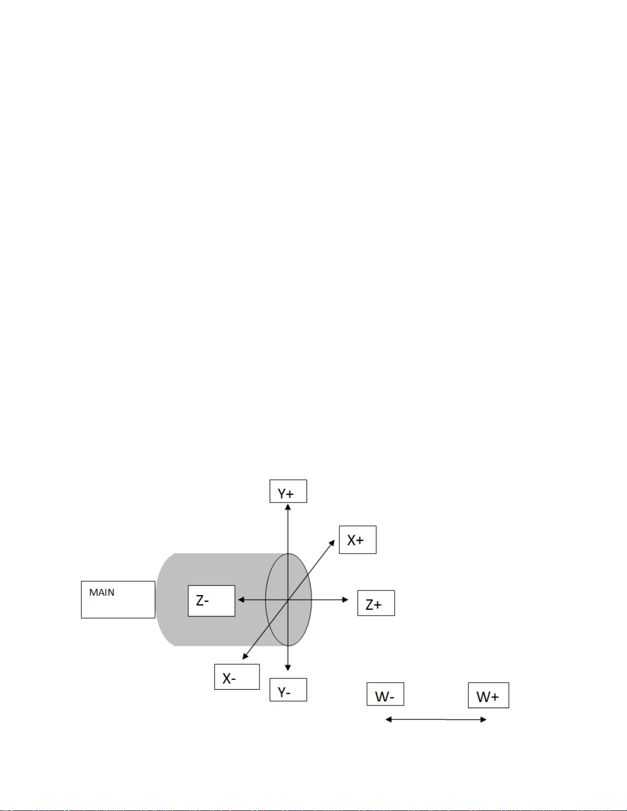
There are two additional axis map codes used for milling
on the main spindle utilizing the Y axis.
G103 - Milling on the face of the part with Y axis
G104 - Milling on the diameter of the part with Y axis
Everything is programmed very similar to the G101 map
code. The only differences are
C axis can be used to position the material.
No polar interpolation in this map.
Y axis is used instead of polar interpolation.
G103 AXIS MAP DIAGRAM
Page 39

Why use a Y axis?
On the face of the part there isn’t any reason to use the Y
axis in theory. The machine with a G101 map could very easily
hit every angle, and cut every feature. However Angular
accuracy is decreased as the machine gets further away from
the center of rotation.
The Y axis is a True linear move, and will cut a true flat and
will help eliminate angular inaccuracies.
The C axis with the G101 map will cut a flat surface,
however it is polar interpolation and may not be as flat as a
surface cut with the linear Y axis in the G103 map. The
inaccuracy from the G101 map will be very small and in some
instances very difficult to measure.
If the work is small, smaller than 2 inches, and the tool will
be traveling close to center it may be best to use the G103 map
so the C axis isn’t rotating around as much. This really is
personal preference.
Page 40

Milling with the Linear Y G103 Axis Map
First step is to call the tool
On all Y axis lathes the tool change block will be different from
the two axis and live tool machine.
Since we are adding another axis an offset for the axis must be
able to be applied in case live tools are shifted, or gang tool
holders are used.
G103 (ALLOWS THE Y AXIS TO BE USED)
T0707 (CALLS UP THE TOOL AND APPLIES OFFSET)
Y0. (SHIFTS THE TOOL SO THAT THE TIP IS AT THE CENTER OF ROTATIONS)
G109 (RETURNS TO TURNING AXIS MAP)
Now the tool has been correctly positioned we are ready to
turn the live tool spindle on and start an approach.
G103
G7
M131
G97 M33 S1500
G54
G94
G0 C0.
Z.25
X.625
From here a square profile will be milled with the y axis
Y.625
G01 Z-.875 F50.
Y-.625 F10.
X-.625
Y.625
X.625
G0 Z.25
Page 41
Next we will return everything back to turning settings and call
up the next tool.
G109
M130
G95
G8
M35
G28 U0. W0.
From this point the final axis map code for the main spindle will
be covered.
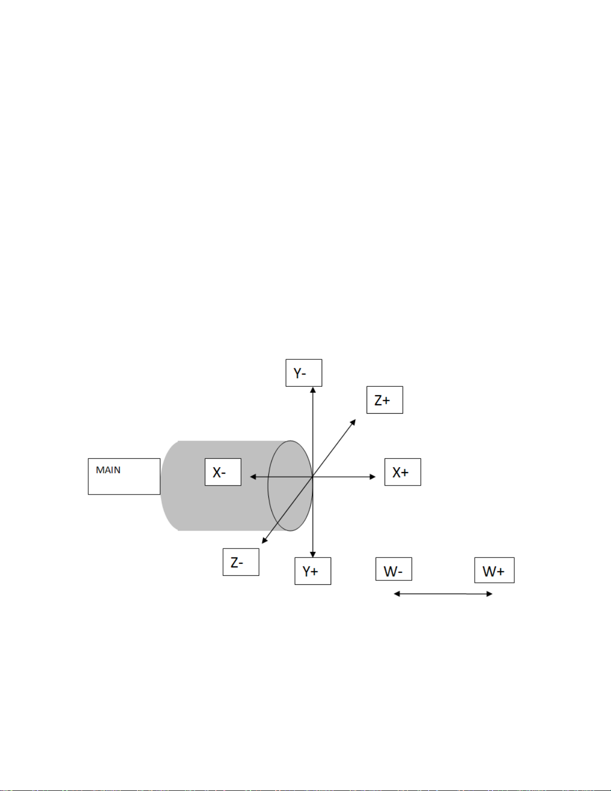
G104 AXIS MAP DIAGRAM
This axis map is defined similar to the G102 however the Y axis
is not wrapped around the part, in this map it is linear up and
down.
Page 42

This map can use a G25 Q0. If programming around the
center is desired, or programmed where Z0. is the diameter of
the bar.
To begin a tool must be called and positioned
G103 (ALLOWS THE Y AXIS TO BE USED)
T0606 (CALLS UP THE TOOL AND APPLIES OFFSET)
Y0. (SHIFTS THE TOOL SO THAT THE TIP IS AT THE CENTER OF ROTATIONS)
G109 (RETURNS TO TURNING AXIS MAP)
G104
G7
G25 Q0.
M131
G97 M33 S1500
G54
G94
G0 C0.
X-.75
Z1.25
From here a pocket can be programmed
Y.5
G01 Z.5
Y-.5
G0 Z1.25
G109
M130
G95
G8
M35
G28 U0. W0.
Page 43

STOP!
If the machine to be programmed is one of the
following machines all the post information
needed is above.
Please refer to the 2 axis section for cutoff
example.
TMX8MY
TMX10MY
This includes any machine above with the letter
“i” afterward
Page 44

The following will apply to sub spindle machines.
Part Transfer
The first step is recognizing that the work will be transferred
and positioned inside the machine so we will need to setup a
new work offset.
On the input screen press part setup.
Page 45
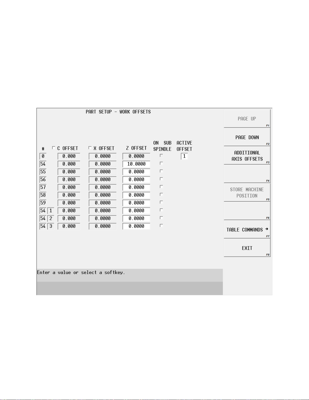
At the point the screen will look similar to this.
The G54 value will most likely not be 10 inches, this is only here as an
example.
Page 46
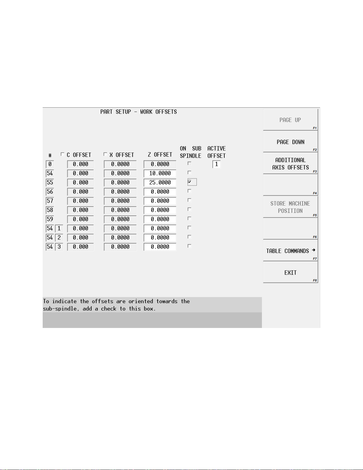
On this page there needs to be an offset with the sub
spindle check box selected.
This will allow the sub spindle to rotate instead of the mail spindle.
From here an offset for the “W” axis can be set on the
main spindle offset and sub spindle
The offset should be set with the sub spindle on the face of the part. This will
allow the “W” axis to be positioned to the face of the part, and then feed onto the
part an exact distance.
Page 47
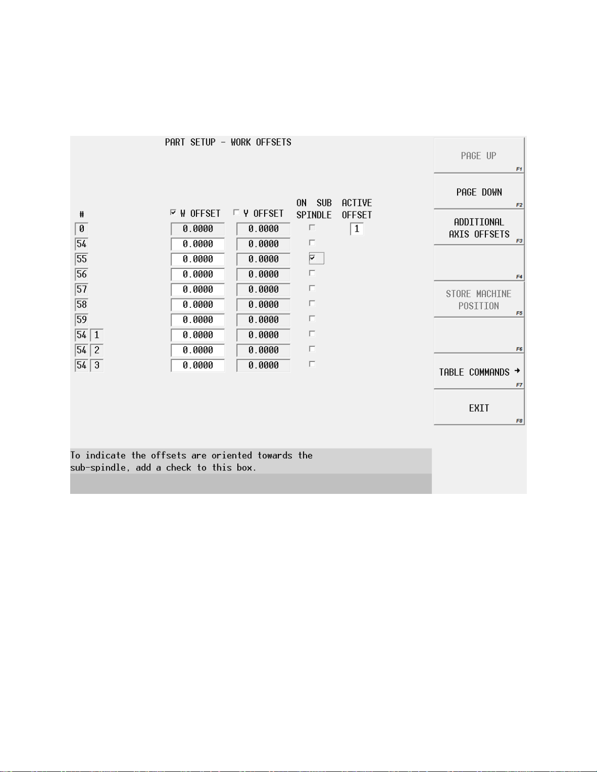
On the last screen press additional offsets, this page with
the “W” axis will become available.
The check box for the “W” offset will need to be selected, and then the machine
can jog to the front of the part and the position can be stored.
The spindle can then be jogged to a safe position and an offset can be stored for
the position of the “W” offset relative to the second offset. This position is
normally around 2 inches in front of the limit.
When the machine is setup this way it is very easy to program the transfer
because any move positive will be in front of the part, and any move negative will
be onto the part.
Page 48

The part transfer should be programmed as follows
G109 (TURNING MAP)
M130 (TURNING MODE)
G0 G54 (CALLS MAIN SPINDLE OFFSET)
M203:0 (COMMANDS SPINDLE SYNC AT 0 DEGREES)
G97 M3 S500 (TURNS THE MAIN SPINDLE ON AT A FIXED RPM)
M241 (ALLOWS THE SUB SPINDLE TO OPEN WHILE ROTATING)
M114 (SUB-SPINDLE OPEN)
G94 (INCHES PER MINUTE)
G152 G0 W1. (G152 COMMANDS THAT THE W AXIS IS TO MOVE)
M186 (ACTIVATE W AXIS TORQUE MONITORING)
G152 G1 G6 W-.5 F50. (COMMANDS THE W AXIS TO MOVE WITH TORQUE MONITORING ON)
M187 (STOP TORQUE MONITORING)
M115 (CLOSE SUB SPINDLE CHUCK)
M231 (ALLOWS MAIN SPINDLE TO OPEN WHILE CHUCK IS ROTATING)
M69 (OPEN THE MAIN CHUCK)
G55 G152 G0 W0. (MOVE W AXIS TO THE SECOND PART OFFSET)
M68 (CLOSE MAIN SPINDLE)
M5 (STOP SPINDLE)
M205 (CLEAR SPINDLE SYNC)
This code is acceptable to transfer the part, however if bar stock is going to be
used the sub spindle will need to pull the stock out to the next position and a
cutoff will need to be programmed.
Page 49

The part cutoff with bar pull should be programmed as
follows
G103 (CALLS MAP WITH Y AXIS AVAILABLE)
T0505 (CALLS TOOL AND APPLIES OFFSETS)
Y0. (SHIFTS THE TOOL TO Y 0.)
G109 (TURNING MAP)
G92 S1000 (SETS MAX RPM AT 1000RPM)
G97 M3 S500 (TURNS THE SPINDLE ON AT 500RPM)
G54 (CALLS MAIN SPINDLE OFFSET)
Z.05 (MOVES THE CUTOFF TOOL INFRONT OF PART)
G109 (TURNING MAP)
M130 (TURNING MODE)
G0 G54 (CALLS MAIN SPINDLE OFFSET)
M203:0 (COMMANDS SPINDLE SYNC AT 0 DEGREES)
M241 (ALLOWS THE SUB SPINDLE TO OPEN WHILE ROTATING)
M114 (SUB-SPINDLE OPEN)
G94 (INCHES PER MINUTE)
G152 G0 W1. (G152 COMMANDS THAT THE W AXIS IS TO MOVE)
M186 (ACTIVATE W AXIS TORQUE MONITORING)
G152 G1 G6 W-.875 F50. (COMMANDS THE W AXIS TO MOVE WITH TORQUE MONITORING ON)
M187 (STOP TORQUE MONITORING)
M115 (CLOSE SUB SPINDLE CHUCK)
M231 (ALLOWS MAIN SPINDLE TO OPEN WHILE CHUCK IS ROTATING)
M69 (OPEN THE MAIN CHUCK)
G152 G0 W.975 (MOVE W AXIS TO CUTOFF POSITION)
(Part length – Feed distance onto the part + cutoff tool width + stock to face off for next part +
stock for sub spindle to face)
(1.625 - .875 + .125 + .05 + .05 = .975)
M68 (CLOSE MAIN SPINDLE)
G95
G0 X2.1
G1 X1.85 F.003
G0 X2.1
Z.15
G1 X2.
Z.1
X1.9 Z.05
X-.04
Page 50
X2.25
M5 (STOP SPINDLE)
M205 (CLEAR SPINDLE SYNC)
G55 G152 W0. (POSITION SUB SPINDLE FOR SECOND WORK OFFSET)
G28 U0. (POSITION TOOL AT HOME IN X POSITION FOR TOOL CHANGE)
G28 W0. (POSITION TOOL AT HOME IN Z POSITION FOR TOOL CHANGE)
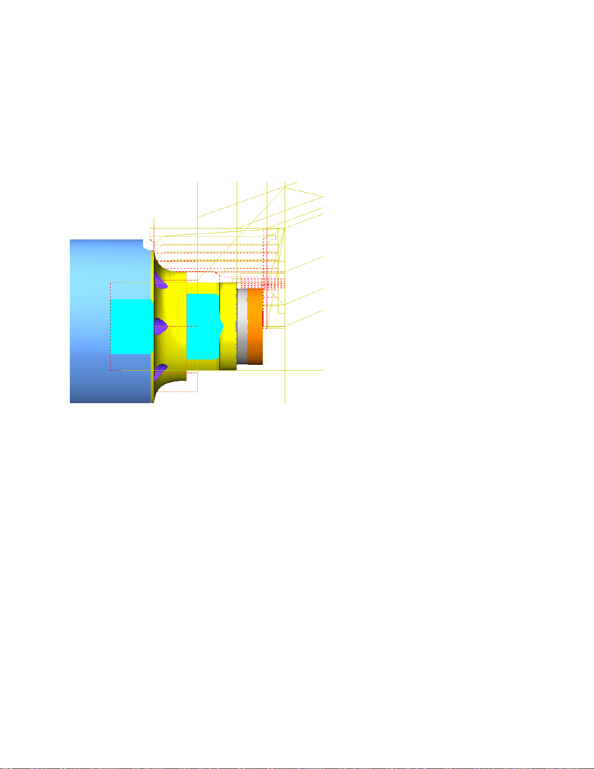
The main spindle graphics do not show the part being
pulled.
A Hurco MYS machine (equipped with a sub spindle) can
turn between spindles. The example above should be used up
until the move to position the part for the cutoff, at that point
you could insert turning, milling, drilling, or any operation
desired instead of cutting the part off.
The machine will need to perform the spindle sync and the
positioning of the bar inside of the program, so all features will
need to be programmed and ran at that time.
Page 51

The final examples will show how to program on the sub
spindle.
Tools
9. Sub Spindle Turning Tool
Turning on the sub spindle is identical to the main with one
difference, all moves will be positive instead of negative.
G103
T0909
Y0.
G109
G92 S1500
G97 M3 S500
G0 G95 Z-.25
X2.25
G96 G1 X2.1 F.004 (CONSTANT SURFACE SPEED)
G72 U.1 R.1 (U is depth of cut R is retract distance)
G72 P5 Q6 U0.005 W0.005 F.002 S1000 T0101
N5 G1 X2.0 Z0.
X-.04
N6 Z-.05
G0 X2.25 Z-.25 (RETURN TO SAFE POSITION)
G70 P5 Q6 F.002 S1000
G0 X2.25 Z-.25 (RETURN TO SAFE POSITION)
M5 (STOP SPINDLE)
G28 U0.
G28 W0.
When machining on the sub spindle the X should be sent
home first and then the Z.
 Loading...