

Hupfer TE-2/V27-33, TE-2/VK19-26, TEH-2/V19-26, TEH-2/V27-33, TEUH-1/VS19-26 Operating Instructions Manual
...
Ope
rating Instructions
TE-2/V19-26
Plat
e dispenser
| TE-2/V27-33 | TE-2/VK19-26 | TEH-1/V19-26 |
TEH-1/V27-33 | TEH-2/V19-26 | TEH-2/V27-33 | TEUH-1/VS19-26
| TEUH-2/VS19-26| TEUH-2/VC19-26 | EBR/V19-26 | EBR/V27-
33 | EBRH/V19-26 | EBRH/V27-33 | EBRH-2/V19-26
4330000_A1

Ch
apter 1 Introduction
Page 2 Appliance Information
1 Intr
1.
1 Appliance Information
oduction
Ap
pliance designation Plate dispenser
Appliance type/ -s TE-2/V19-26 | TE-2/V27-33 | TE-2/VK19-26 | TEH-
Manufacturer HUPFER® Metallwerke GmbH & Co. KG
www.hupfer.de
info@hupfer.de
Plate dispenser
1/V19-26 | TEH-1/V27-33 | TEH-2/V19-26 | TEH-2/V2733 | TEUH-1/VS19-26 | TEUH-2/VS19-26| TEUH2/VC19-26 | EBR/V19-26 | EBR/V27-33 | EBRH/V19-26 |
EBRH/V27-33 | EBRH-2/V19-26
Dieselstraße 20
48653 Coesfeld
PO 1463
D-48634 Coesfeld
+49 2541 805-0
+49 2541 805-111
TE-2/V19-26 | TE-2/V27-33 | TE-2/VK19-26 | TEH-1/V19-26 | TEH-1/V27-33 | TEH-2/V19-26 |
TEH-2/V27-33 | TEUH-1/VS19-26 | TEUH-2/VS19-26| TEUH-2/VC19-26 | EBR/V19-26 |
EBR/V27-33 | EBRH/V19-26 | EBRH/V27-33 | EBRH-2/V19-26
Read these operating instructions carefully before the first operation of the appliance.
Ensure that sources of danger and possible faulty operations have been pointed out to the operating staff.
Subject to modifications
The products covered by these operating instructions have been developed taking into consideration the requirements of the market and the latest technology. HUPFER® reserves the right to modify the products and
appertaining technical documentation in so far as the modifications are in the name of technological progress. The data and weights as well as the description of performance and functions assured in the order
confirmation as binding are always decisive.
Manual edition
4330000_A1
Plate dispenser
TE-2/V19-26, 27-33 | TE-2/VK19-26 | TEH-1/V19-26, 27-33 | TEH-2/V19-26, 27-33 | TEUH-1/VS19-26 | TEUH-2/VS19-26, 27-33 | TEUH-2/VC19-26
EBR/V19-26, 27-33 | EBRH/V19-26, 27-33 | EBRH-2/V19-26 4330000_A1

In
troduction Chapter 1
Table of Contents Page 3
1.
2 Table of Contents
1 Int
roduction 2
1.1 Appliance Information 2
1.2 Table of Contents 3
1.3 List of abbreviations 5
1.4 Definitions of Terms 6
1.5 Orientation Guide 7
1.6 Notes on Use of Manual 8
1.6.1 Notes on the manual structure 8
1.6.2 Notes and their illustrations used in the chapters 8
2 Safety Instructions 9
2.1 Introduction 9
2.2 Warning Symbols Used 9
2.3 Safety Instructions for Appliance Safety 9
2.3.1 Safety instructions for all appliances 9
2.3.2 Additional safety instructions for heated appliances 10
2.4 Safety Instructions for Cleaning and Care 11
2.5 Safety Instructions for Trouble Shooting 11
2.6 Notes on Specific Hazards 11
3 Description and Technical Data 12
3.1 Performance Description 12
3.2 Intended Use 12
3.3 Improper Use 12
3.4 Appliance Description 13
3.4.1 View of the appliance - Plate dispenser 13
3.4.2 View of the appliance - Built-in plate dispenser 13
3.4.3 Appliance Description 14
3.4.4 Optional accessories 14
3.5 Technical Data 15
3.6 Rating plate 19
4 Transport, Assembly, Putting into Operation and Decommissioning 20
4.1 Transport 20
4.2 Assembly (Built-in appliances only) 20
4.2.1 Unheated appliances (EBR/V19-26 | EBR/V27-33) 20
4.2.2 Heated appliances (EBRH/V19-26 | EBRH/V27-33 | EBRH-2/19-26) 22
4.3 Putting into Operation 26
4.4 Storage and Recycling 26
5 Operation 27
5.1 Arrangement and Function of the Operating Elements 27
5.2 Plate Dispenser Adjustment 27
5.2.1 Crockery guide adjustment 28
Plate dispenser
4330000_A1 TE-2/V19-26, 27-33 | TE-2/VK19-26 | TEH-1/V19-26, 27-33 | TEH-2/V19-26, 27-33 | TEUH-1/VS19-26 | TEUH-2/VS19-26, 27-33 | TEUH-2/VC19-26
EBR/V19-26, 27-33 | EBRH/V19-26, 27-33 | EBRH-2/V19-26

Ch
apter 1 Introduction
Page 4 Table of Contents
5.2.2 Sp
ring adjustment 29
5.2.3 Calculating the plate dispenser capacity 30
5.3 Operation 31
5.3.1 Switching on the appliance 32
5.3.2 Loading the appliance 32
5.3.3 Moving the appliance 34
5.4 Measures at the End of the Operation 34
6 Fault Detection and Trouble Shooting 35
6.1 Security Measures 35
6.2 Notes on Trouble Shooting 35
6.3 Fault and Action Table 35
7 Cleaning and Care 36
7.1 Security Measures 36
7.2 Hygiene Measures 36
7.3 Cleaning and Care 36
7.4 Special Care Instructions 37
8 Replacement Parts and Accessories 38
8.1 Introduction 38
8.2 Spare Parts and Accessories List 38
Plate dispenser
TE-2/V19-26, 27-33 | TE-2/VK19-26 | TEH-1/V19-26, 27-33 | TEH-2/V19-26, 27-33 | TEUH-1/VS19-26 | TEUH-2/VS19-26, 27-33 | TEUH-2/VC19-26
EBR/V19-26, 27-33 | EBRH/V19-26, 27-33 | EBRH-2/V19-26 4330000_A1

In
troduction Chapter 1
List of abbreviations Page 5
1.
3 List of abbreviations
Ab
breviation
BG
R
BG
V
CE Co
DI
N
EC Eu
EN Eu
E/
V
IP In
LE
D
De
finition
Ru
le of the Professional Association
Re
gulation of the Professional Association
mmunauté Européenee
Eu
ropean Community
De
utsches Institut für Normung
Ge
rman Institute for Standardisation, technical regulations and technical specifications
ropean Community
Eu
ropean Union
ropean Standard
Ha
rmonised standard for the EU market
Sp
are and wearing part
ternational Protection. The abbreviation IP and a further two-digit index specify the
prot
ection class of a housing.
Th
e first digit: Protection against ingress of solid foreign objects The second digit: Protection against ingress of
wa
ter
0 No
protection against contact, no protec-
ti
on against ingress of solid foreign
obj
ects
1 Pr
otection against contact with any large
su
rface of the body such as the hand,
pr
otection against ingress of foreign
obj
ects >1.97 in
2 Pr
otection against contact with the
fi
ngers, protection against ingress of
fo
reign objects >0.47 in
3 Pr
otection against contact with tools,
th
ick wires or similar objects of >0.1
in
, protection against foreign objects
>0
.1 in
4 Pr
otection against contact with tools,
th
ick wires or similar objects of >0.04
in
, protection against foreign objects
>0
.04 in
5 Pr
otection against contact, protection
agai
nst dust deposits inside
6 Co
mplete protection against contact,
pr
otection against ingress of dust
7 Pr
8 Pr
Li
ght Emitting Diode
Li
ght diode
0 No
protection against ingress of water
1 Pr
otection against vertically falling water
dr
ops
2 Pr
otection against dripping water (at any
angl
e up to 15° from the vertical)
3 Pr
otection against water drips at any
angl
e up to 60° from the vertical
4 Pr
otection against water splashing from
an
y direction
5 Pr
otection against water jets (projected
by
a nozzle) at any angle
6 Pr
otection against temporary flooding
otection against ingress of water
dur
ing temporary immersion
otection against pressurised water
dur
ing continuous immersion
Plate dispenser
4330000_A1 TE-2/V19-26, 27-33 | TE-2/VK19-26 | TEH-1/V19-26, 27-33 | TEH-2/V19-26, 27-33 | TEUH-1/VS19-26 | TEUH-2/VS19-26, 27-33 | TEUH-2/VC19-26
EBR/V19-26, 27-33 | EBRH/V19-26, 27-33 | EBRH-2/V19-26

Ch
apter 1 Introduction
Page 6 Definitions of Terms
1.
4 Definitions of Terms
Te
rm
Au
thorised specialist
Co
ver
Co
ok&Chill-Kitchens
Co
ok&Serve-Kitchens
El
ement formation
Sp
ecialist
Li
ft
Co
ntrol
Co
nvection
Co
rrosion
Ma
chine safety
Pa
ssive layer
Ch
eck
Qu
alified person,
qual
ified staff
Sc
huko®
In
structed persons
De
finition
An
authorised specialist is a specialist that has been trained by the manufacturer, an
aut
horised service dealer or a company assigned by the manufacturer.
A b
ell-shaped cover for keeping food warm on plates and dishes.
"C
ook and Chill": Kitchens where warm food after being cooked is chilled as quickly as
pos
sible.
"C
ook and Serve": Kitchens where warm food is served immediately after being coo-
ke
d or kept warm until it is consumed.
Al
so: contact corrosion. Occurs when different noble metals are in close contact with
eac
h other. This happens when a corrosive medium is between both metals, as for
ex
ample water or even air humidity.
A
specialist is a person who can evaluate work assigned and can individually recog-
ni
se any possible dangers due to the professional training, specialist knowledge and
ex
perience as well as knowledge of the respective guidelines.
A
movement, for example a vertical movement of the guide basket from bottom to top.
Co
mpare with certain conditions and/or characteristics such as damages, leaks, filling
le
vels, heat.
Ph
ysical properties or mass transfer (e.g. heat or cold) through currents in gases and
liq
uids.
Th
e chemical reaction of a metallic material with its surroundings, e.g. rust.
Th
e term of machine safety means all the measures used to avert injury to persons.
Th
e basis for this are national as well as EC-wide valid directives and laws for protect-
in
g users of technical devices and systems.
A n
on-metallic protective layer on a metallic material that prevents or slows down
ma
terial corrosion.
Co
mpare with certain values such as weight, torque, content, temperature.
Qu
alified personnel are persons who due to their professional training, experience and
in
struction as well as their knowledge of the respective standards, guidelines, accident
prev
ention regulations and operating conditions have been authorised by a person
res
ponsible for system safety to carry out required activities and can recognise and
prev
ent any possible danger (definition of specialists according to IEC 364).
Th
e abbreviation of the German term "Protective contact" that indicates a system of
dom
estic plugs and sockets equipped with protective earthed contacts used in most of
Eu
rope.
An
instructed person is a person who has been instructed on the possible risks result-
in
g from improper behaviour when carrying out the assigned task as well as on the
nec
essary protective equipment and protective measures and trained for this task if
nec
essary.
Plate dispenser
TE-2/V19-26, 27-33 | TE-2/VK19-26 | TEH-1/V19-26, 27-33 | TEH-2/V19-26, 27-33 | TEUH-1/VS19-26 | TEUH-2/VS19-26, 27-33 | TEUH-2/VC19-26
EBR/V19-26, 27-33 | EBRH/V19-26, 27-33 | EBRH-2/V19-26 4330000_A1

In
troduction Chapter 1
Orientation Guide Page 7
1.
5 Orientation Guide
The f
ront
"The front" means the side of the plate dispenser where the push bars are arranged. The operating staff
stays at this side to move the appliance.
The side of the built-in appliances named as "the front" means the side, at which the staff operates the plate
dispenser.
The rear
The side named "the rear" means the opposite side of the front side (the front).
The right
The side named "the right" means the side at the right hand side of the front side (the front).
The left
The side named "the left" means the side at the left hand side of the front side (the front).
Plate dispenser
4330000_A1 TE-2/V19-26, 27-33 | TE-2/VK19-26 | TEH-1/V19-26, 27-33 | TEH-2/V19-26, 27-33 | TEUH-1/VS19-26 | TEUH-2/VS19-26, 27-33 | TEUH-2/VC19-26
EBR/V19-26, 27-33 | EBRH/V19-26, 27-33 | EBRH-2/V19-26
Ch
apter 1 Introduction
Page 8 Notes on Use of Manual
1.
6 Notes on Use of Manual
1.
6.1 Notes on the manual structure
This manual is structured in functional and task orientated chapters.
1.6.2 Notes and their illustrations used in the chapters
DANG
ER Brief description of danger
Th
ere is an imminent danger to life and limb of the user and / or third parties
when the instructions are not followed precisely or the circumstances described are not taken into account.
The type of danger is indicated by a symbol and explained in the accompanying text in more detail. In this example the general sign of danger is used.
WA
RNING Brief description of danger
Th
ere is an indirect danger to life and limb of the user and / or third parties
when the instructions are not followed precisely or the circumstances described are not taken into account.
The type of danger is indicated by a symbol and explained in the accompanying text in more detail. In this example the general sign of danger is used.
AT
TENTION Brief description of danger
Th
ere is a potential risk of injury or damage to property when the instructions
are not followed precisely or the circumstances described are not taken into
account.
The type of danger is indicated by a general sign and explained in the accompanying text in more detail. In this example the general sign of danger is used.
NO
TE Brief description of additional information
At
tention is pointed to special conditions or additional important information on
the respective subject.
IN
FO Short title
Co
ntains additional information on work assisting features or recommenda-
tions on the respective subject.
Plate dispenser
TE-2/V19-26, 27-33 | TE-2/VK19-26 | TEH-1/V19-26, 27-33 | TEH-2/V19-26, 27-33 | TEUH-1/VS19-26 | TEUH-2/VS19-26, 27-33 | TEUH-2/VC19-26
EBR/V19-26, 27-33 | EBRH/V19-26, 27-33 | EBRH-2/V19-26 4330000_A1
Sa
fety Instructions Chapter 2
Introduction Page 9
2 Sa
2.
1 Introduction
fety Instructions
Th
e chapter on safety instructions describes the risks associated with the appliance in terms of product liabil-
ity (according to the EU Directive).
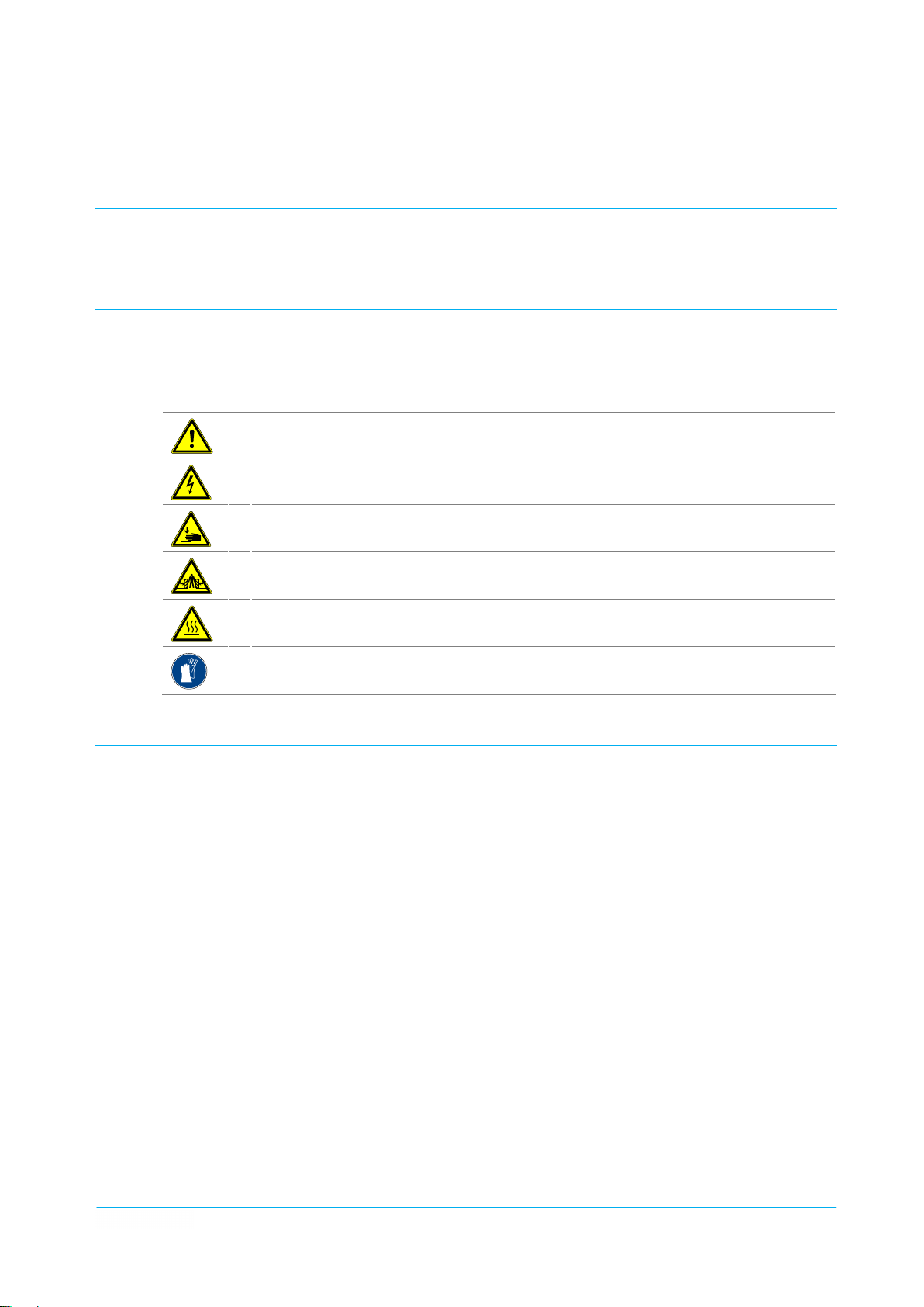
2.2 Warning Symbols Used
Sy
mbols are used in these operating instructions to point out the dangers that can occur while operating or
cleaning the appliance. In both cases, the symbol provides information on the type and circumstances of
danger.
The following symbols can be used:
Ge
neral hazardous area
Ha
zardous electrical voltage
Ri
sk of hand injuries
Ri
sk of squashing
Ri
2.
3 Safety Instructions for Appliance Safety
Sa
fe operation of the appliance depends on appropriate and thorough use. Negligent handling of the appliance can lead to danger to life and limb of the user and / or third parties as well as hazards to the appliance
itself and the other operator's property.
2.3.1 Safety instructions for all appliances
The following points are to be observed to ensure the appliance safety:
sk of hot surfaces
We
ar hand protection
The appliance may only be operated when it is in perfect condition with regards to technical stan-
dards.
All the operating and actuating elements must be in a perfect and functionally reliable condition with
regards to technical standards.
Modifications or retrofits of the equipment are only permitted in consultation with the manufacturer
and on receipt of his written agreement.
In no case may people sit or stand on the appliance. Transport of persons is not permitted.
Before loading, the crockery dispensing height must be adjusted to the kind of crockery used.
The crockery guides must be adjusted to the kind of crockery used before loading.
To avoid injuries to the hands, care should always be taken to ensure that the crockery dispensing
height does not fall below the upper rim of the housing.
Never push the guide basket down manually into the dispensing tube (e.g. for cleaning). There is a
risk of injury, if the guide basket is released.
Plate dispenser
4330000_A1 TE-2/V19-26, 27-33 | TE-2/VK19-26 | TEH-1/V19-26, 27-33 | TEH-2/V19-26, 27-33 | TEUH-1/VS19-26 | TEUH-2/VS19-26, 27-33 | TEUH-2/VC19-26
EBR/V19-26, 27-33 | EBRH/V19-26, 27-33 | EBRH-2/V19-26

Ch
apter 2 Safety Instructions
Page 10 Safety Instructions for Appliance Safety
Th
e appliance is provided exclusively for manual transport. Mechanical transport is not permitted.
Risk of injury and damage.
If a stack of plates with the covers is too high, do not push it down forcibly. There is a risk of injury, if
the locking is released. Furthermore, the locking function of the covers can be damaged.
Release both total brakes before commencing transporting. Moving the appliance with the total bra-
kes locked can damage the chassis
Transport should only be undertaken over level floors. Moving the appliance over very uneven floors
can damage the chassis.
Transport over inclined planes or steps is not permitted.
When approaching walls and moving round obstacles always pay attention to persons in the way.
Risk of injury.
When transporting the appliance, always hold both bars with your hands. Never let go of the appli-
ance while moving it.
When transporting the appliance, do not move it faster than a walking pace. Heavily laden plate dis-
pensers are difficult to brake and steer. If necessary, ask for assistance when transporting the appliance.
If the plate dispenser tips over due to outside influences or inattention, never catch it manually. Risk
of injury.
Do not stop the appliance on sloping floors.
After stopping, the appliance should be secured against rolling away by means of both total brakes
being applied.
In the case of offsite transport in a vehicle such as a lorry, the appliances should be secured properly.
The total brakes are not sufficient as a transport securing method.
2.3.2 Additional safety instructions for heated appliances
The heated appliances can only be operated by instructed specialists and kitchen staff and under
continuous supervision.
Heated plate dispensers are intended for dispensing heated crockery. Their use for cooking food and
keeping it warm or for room heating is not permitted.
The crockery temperatures can exceed the permitted maximum temperatures of 149°F (65°C) for
touchable appliance surfaces. Always wear protective gloves when dispensing hot crockery. Risk of
burning.
During operation of the appliance, never reach into it and touch the heating element with the fingers.
Risk of burning.
Plastic crockery, top and bottom parts of plastic insulated sets and plastic-coated items for keeping
food warm should not be stored or warmed up in heated plate dispensers. Owing to the high temperatures of the heating elements, the plastics can melt and catch fire.
The base plate and used air from the base outlets can become very hot. The appliance should not be
operated on fibre-based floor coverings (e.g. carpets, mats).
Before transporting, switch off the appliance, pull out the mains plug and insert it into the plug park
provided.
Forceful straining of the connecting cable can lead to damage to the internal line. Risk of fire.
Never pull the mains plug out of the socket by the wire. The standard models of HUPFER
ances are equipped with a Schuko® angle plug. In contrast to a straight Schuko® plug this plug only
sticks insignificantly out of the socket and so cannot be damaged by being hit at the side. If the appliance is moved without pulling out the mains plug beforehand, the socket can be severely damaged or
even pulled out from the wall as a result of leverage arising from overstretching of the connecting cable.
Never move the appliance by pulling by the connecting cable.
If the mains plug has come into contact with water it must be dried before inserting it into the socket.
Danger to life.
®
appli-
Plate dispenser
TE-2/V19-26, 27-33 | TE-2/VK19-26 | TEH-1/V19-26, 27-33 | TEH-2/V19-26, 27-33 | TEUH-1/VS19-26 | TEUH-2/VS19-26, 27-33 | TEUH-2/VC19-26
EBR/V19-26, 27-33 | EBRH/V19-26, 27-33 | EBRH-2/V19-26 4330000_A1

Sa
fety Instructions Chapter 2
Safety Instructions for Cleaning and Care Page 11
Da
maged mains plugs or connecting cables are to be replaced by authorised personnel before the
appliance is reused.
Do not use any extension cables in wet and damp areas.
Only insert mains plugs into suitable sockets. If the mains plug does not fit, the connecting cable of
the appliance is to be retrofitted by authorised specialist staff.
The use of socket adapters is not permitted. Risk of fire.
Do not clean the appliance with steam-jet or high-pressure washers. The appliance must be taken
out of operation and switched off at the mains beforehand in any area where steam-jet or highpressure washers are to be used.
2.4 Safety Instructions for Cleaning and Care
Th
e following points shall be observed when carrying out any cleaning and maintenance operations:
For reasons of hygiene the cleaning instructions shall be strictly observed.
Take the appliance out of operation before starting the cleaning process. Pull out the mains plug and
insert it into the plug park located on the appliance.
For cleaning, the appliance must be out of operation and cooled down sufficiently.
Do not clean the appliance with steam-jet or high-pressure washers. The appliance must be taken
out of operation and switched off at the mains beforehand in any area where steam-jet or highpressure washers are to be used.
Even appliances without an electrical connection should not be cleaned with running water or pres-
surised water.
2.5 Safety Instructions for Trouble Shooting
Th
e following points shall be observed when carrying out any maintenance and trouble shooting operations:
All trouble shooting work should only be carried out by authorised specialists.
When carrying out trouble shooting work, it must be ensured that the appliance is switched off. When
operating on the electrical installation, the appliance is to be switched off at the mains and secured
against reactivation.
The local applicable Accident Prevention Regulations must be observed.
Defective components should only be replaced with original parts.
2.6 Notes on Specific Hazards
El
ectrical energy
All work on the electrical installations should only be carried out by a certified electrician or by author-
ised specialists under supervision and monitoring of a certified electrician according to the certain electro-technical regulations.
The appliances that inspection, maintenance and trouble shooting work is performed on must be
switched voltage free on and secured against reactivation, when the voltage is not required for this
kind of work. This must only be carried out by a certified electrician.
Plate dispenser
4330000_A1 TE-2/V19-26, 27-33 | TE-2/VK19-26 | TEH-1/V19-26, 27-33 | TEH-2/V19-26, 27-33 | TEUH-1/VS19-26 | TEUH-2/VS19-26, 27-33 | TEUH-2/VC19-26
EBR/V19-26, 27-33 | EBRH/V19-26, 27-33 | EBRH-2/V19-26

Ch
apter 3 Description and Technical Data
Page 12 Performance Description
3 Des
3.
1 Performance Description
cription and Technical Data
Pl
ate dispensers are intended for storage of clean crockery items ready for use in the food service industry
and large-scale catering establishments. They are used mainly for storage of warmed crockery ready for use
on food distribution belts and storage of plates at normal temperature or chilled on self-service counters in
bistros or cafeterias.
There are various models available for selection. Depending upon the size and number of crockery items,
the plate dispensers are available in two sizes, 19-26 (for plates with a diameter of 7.48'' to 10.24'') and 2733 (for plates with a diameter of 10.63'' to 13'').
The unheated models with the enclosed side and front walls of the housing store crockery items ready for
use for serving portions of cold dishes.
The unheated models with cooling slots store crockery ready for serving portions of cold side dishes, e.g. salads and desserts.
The models heated by air circulation are intended for storage of crockery ready for serving portions of warm
components. The crockery can be heated up to 212°F (100°C).
Besides the mobile plate dispensers, there are plate dispensers intended for installation in worktops.
3.2 Intended Use
Pl
ate dispensers are intended exclusively for storage of clean plates with diameter of 7.48'' to 10.24'' or
10.63'' to 13'' ready for use. Depending on the model, the loaded plates can be cooled down or heated up.
The appliances are intended for transporting round china items or transport made of toughened glass.
Transport of other loads is not permitted.
The intended use means the predetermined procedures, compliance with the indicated specifications and
use of the delivered or additionally available original accessories.
Any other use of the appliance is considered as unintended use.
3.3 Improper Use
It i
s not permitted to load the plate dispenser with other loads as given.
In no case may people sit or stand on the appliance or be transported on it.
Moreover, it is not permitted to use the heated plate dispensers for cooking food or keeping it warm and for
room heating.
No flammable or outgasing objects, objects with plastic items or foodstuff should be stored under the plate
dispenser.
No liability is assumed and no warranty claims can be submitted for damages caused by improper use.
Plate dispenser
TE-2/V19-26, 27-33 | TE-2/VK19-26 | TEH-1/V19-26, 27-33 | TEH-2/V19-26, 27-33 | TEUH-1/VS19-26 | TEUH-2/VS19-26, 27-33 | TEUH-2/VC19-26
EBR/V19-26, 27-33 | EBRH/V19-26, 27-33 | EBRH-2/V19-26 4330000_A1

De
scription and Technical Data Chapter 3
Appliance Description Page 13
3.
4 Appliance Description
3.
4.1 View of the appliance - Plate dispenser
Fi
gure 1 View of the appliance
1 Push bar 7 Casters without total brakes
2 Thermostat for setting the temperature* 8 Corner bumpers
3 On / Off switch* 9 Guide basket
4 Plug park (dummy socket)* 10 Crockery guide
5 Connecting cable with mains plug* 11 Cover*
6 Casters with total brakes
* heated appliances only
3.4.2 View of the appliance - Built-in plate dispenser
Fi
gure 2 View of the appliance
1 Crockery guide 5 Locking positions for the crockery guide
2 Guide basket 6 Connecting socket for appliance plug*
3 Attachment bar with adjustable springs 7 Thermostat*
4 Guide rail 8 Cover*
* heated appliances only
Plate dispenser
4330000_A1 TE-2/V19-26, 27-33 | TE-2/VK19-26 | TEH-1/V19-26, 27-33 | TEH-2/V19-26, 27-33 | TEUH-1/VS19-26 | TEUH-2/VS19-26, 27-33 | TEUH-2/VC19-26
EBR/V19-26, 27-33 | EBRH/V19-26, 27-33 | EBRH-2/V19-26

Ch
apter 3 Description and Technical Data
Page 14 Appliance Description
3.
4.3 Appliance Description
The plate dispensers accommodate clean chinaware and plates made of toughened glass in a adjustable,
spring-loaded guide basket. Owing to the use of special springs, crockery items are moved automatically
and constantly over the entire lift upwards to a uniform dispensing height.
If necessary, there are various models available. A plate dispenser model 19-26 is particularly suitable for
plates with diameter of 7.48'' to 10.24''. A plate dispenser model 27-33 is particularly suitable for plates with
diameter of 10.63'' to 13''.
All the plate dispensers are universally adjustable appliances suitable for the plate diameters, stack heights
and weights given above. The ergonomically favourable dispensing height can be adjusted within a limit to
persons of different height. Plate dispensers are available as one-tube and two-tube models.
Unheated appliances with enclosed side and front walls store crockery at normal temperature ready for use.
Unheated appliances with cooling slots are particularly suitable to be used in cold stores. When using in the
cold store, the cooling slots arranged on the side and front walls of the appliance housing ensure a rapid exchange of air and cause the cold air to be distributed uniformly inside.
The appliances with electric heating (static or circulating air) pre warm the plates or heat them up to a pre-set
temperature.
Besides the mobile plate dispensers, there are built-in plate dispensers intended for installation in worktops.
Depending on the purpose, the built-in appliances are available in different sizes, as one and two-tube models and heated or unheated.
The operating temperature can be continuously set on the heated plate dispensers. The controller is arranged on the front of the housing and can be adjusted as required when using built-in appliances.
The covers made of plastic protect the crockery against dust and condensed water even during relatively
long periods of temporary storage. Using a cover in the heated appliances lowers the heat loss upwards and
reduces the heating time of the inserted crockery or delays the cooling of pre-warmed crockery. The cover is
included in the scope of delivery of the heated models.
3.4.4 Optional accessories
The following parts can be applied as optional accessories for the plate dispenser:
Plastic cover 7.48''-10.24'' high for plate dispenser model 19-26
Plastic cover 7.48''-10.24'' flat for TEUH-2/VC 19-26 (not suitable for other models)
Plastic cover 10.63''-13' for plate dispenser model 27-33
Swivel casters made of stainless steel, Ø = 4.92'' with and without total brakes, plate attachment
The part numbers of the special accessories can be found in the spare parts catalogue a nd order lists available online.
Plate dispenser
TE-2/V19-26, 27-33 | TE-2/VK19-26 | TEH-1/V19-26, 27-33 | TEH-2/V19-26, 27-33 | TEUH-1/VS19-26 | TEUH-2/VS19-26, 27-33 | TEUH-2/VC19-26
EBR/V19-26, 27-33 | EBRH/V19-26, 27-33 | EBRH-2/V19-26 4330000_A1

De
scription and Technical Data Chapter 3
Technical Data Page 15
3.
5 Technical Data
Di
Vi
ew of the
appl
iance
Pl
Ow
n weight
Pa
yload
Pe
rmitted total
we
ight
Ov
erall dimen-
si
ons
w
x d x h
Op
erating and
am
bient condi-
ti
ons
Ch
assis
Cro
ckery guide
Gu
ide basket
Sta
ck height
wi
thout cover
Sta
ck height with
co
ver
Cro
ckery size
Ca
pacity given in
it
ems (depending
on
the stack
hei
ght)
Nu
mber of cro-
cke
ry stacks
m.
kg
(lbs)
kg
(lbs)
kg
(lbs)
mm
(i
n)
˚C
(˚F)
mm
(i
n)
3
mm
(i
n)
mm
(i
n)
mm
(i
n)
mm
(i
n)
up
2 2 2
TE-2/
V19-26
ate dispenser, unheated
and
without cooling device
31 (
68.3)
140 (
308.6)
171 (
377)
460
(18.11'') x 935 (36.81'')
x
900 (35.43'')
-20
(-4) to 50 (+122)
4
swivel casters, 2 of them
wi
th total brakes, Ø 125
mm
(5'')
adjustable guides per
tu
be, plastic-coated
Ro
d construction, plastic-
co
ated
670 (
26.37’’)
740 (
29.13’’)
190-260 (
and
7.48’’-10.24’’)
to 144 (without cover)
166 (with cover)
TE-2/
V27-33
Pl
ate dispenser, unheated
and
without cooling device
32 (
70.5)
140 (
308.6)
172 (
379)
530
(20.86'') x 1055
(41.
53'') x 900 (35.43'')
-20
(-4) to 50 (+122)
4
swivel casters, 2 of them
wi
th total brakes, Ø 125 mm
(5'
')
3
adjustable guides per
tu
be, plastic-coated
Ro
d construction, plastic-
co
ated
670 (
26.37’’)
740 (
29.13’’)
270-330 (
up
and
10.63’’-13’’)
to 106 (without cover)
122 (with cover)
TE
/-2/VK19-26
Pl
ate dispenser, unheated
wi
th cooling device
29 (
64)
140 (
308.6)
169 (
372.6)
460
(18.11'') x 935 (36.81'')
x
900 (35.43'')
-20
(-4) to 50 (+122)
4
swivel casters, 2 of them
wi
th total brakes, Ø 125 mm
(5'
')
3
adjustable guides per
tu
be, plastic-coated
Ro
d construction, plastic-
co
ated
670 (
26.37’’)
740 (
29.13’’)
190-260 (
up
and
7.48’’-10.24’’)
to 144 (without cover)
166 (with cover)
Plate dispenser
4330000_A1 TE-2/V19-26, 27-33 | TE-2/VK19-26 | TEH-1/V19-26, 27-33 | TEH-2/V19-26, 27-33 | TEUH-1/VS19-26 | TEUH-2/VS19-26, 27-33 | TEUH-2/VC19-26
EBR/V19-26, 27-33 | EBRH/V19-26, 27-33 | EBRH-2/V19-26

Ch
apter 3 Description and Technical Data
Page 16 Technical Data
Di
Vi
ew of the appliance
m. TEH-1/V19-26
TE
H-1/V27-33
TE
H-2/V19-26
TE
H-2/V27-33
Pl
Ow
n weight
Pa
yload
Pe
rmitted total weight kg
Ov
erall dimensions
w
x d x h
Op
erating and ambi-
ent
conditions
Ch
assis
Cro
ckery guide
Gu
ide basket
Sta
ck height without
co
ver
Sta
ck height with
co
ver
Cro
ckery size
Ca
pacity given in
it
ems (depending on
th
e stack height)
Nu
mber of crockery
sta
cks
He
ating
Th
ermostat setting
Ma
ximum crockery
te
mperature
Te
mperature regula-
ti
on
He
at insulation
El
ectrical connection
Po
wer requirement
Pr
otection class
kg
(l
bs)
kg
(l
bs)
(l
bs)
mm
(i
n)
˚C
(˚F
)
mm
(i
n)
3
mm
(i
n)
mm
(i
n)
mm
(i
n)
mm
(i
n)
up
1 1 2 2
Sta
˚C
(˚F
)
˚C
(˚F
)
co
ce
230
kW 0,
IPX
ate dispenser,
heat
ed
30 (
66.13)
70 (
154.32)
100 (
220.46)
460
(18.11'') x 610
(24'
') x 900
(35.
43'')
-20
(-4) to 50
(+
122)
4
swivel casters, 2
of
them with total
brak
es, Ø 125 mm
(5'
')
adjustable guides
per
tube, plastic-
co
ated
Ro
d construction,
pl
astic-coated
670 (26.
37’’)
740 (
29.13’’)
190-260 (
10.
24’’)
7.48’’-
to 72 (without
co
ver) and 83 (with
co
ver)
inless steel
tu
bular heating
el
ement
30-115 (
86-239)
70 (
158)
ntinuous
ramic mat
V 1N AC 50
Hz
9
5
Pl
ate dispenser,
heat
ed
35 (
77.16)
80 (
176.36)
115 (
253.53)
530
(20.86'') x 710
(28.
'') x 900
(35.
43'')
-20
(-4) to 50
(+
122)
4
swivel casters, 2
of
them with total
brak
es, Ø 125 mm
(5'
')
3
adjustable guides
per
tube, plastic-
co
ated
Ro
d construction,
pl
astic-coated
670 (26.
37’’)
740 (
29.13’’)
270-330 (
13’
’)
up
co
ver) and 61 (with
co
ver)
Sta
tu
bular heating
el
ement
30-115 (
70 (
co
ntinuous
ce
ramic mat
230
Hz
0,
9
IPX
10.63’’-
to 53 (without
inless steel
86-239)
158)
V 1N AC 50
5
Pl
ate dispenser,
heat
ed
41 (
90.38)
140 (
308.64)
181 (
399)
460
(18.11'') x 935
(36.
81'') x 900
(35.
43'')
-20
(-4) to 50
(+
122)
4
swivel casters, 2
of
them with total
brak
es, Ø 125 mm
(5'
')
3
adjustable guides
per
tube, plastic-
co
ated
Ro
d construction,
pl
astic-coated
670 (26.
37’’)
740 (
29.13’’)
190-260 (
10.
up
co
ver) and 166
(w
ith cover)
Sta
tu
bular heating
el
ement
30-115 (
80 (
co
ntinuous
ce
ramic mat
230
7.48’’-
24’’)
to 144 (without
inless steel
86-239)
176)
V 1N AC 50
Hz
0,
9
IPX
5
Pl
ate dispenser,
heat
ed
51 (
112.43)
140 (
308.64)
191 (
421)
530
(20.86'') x
1055
(41.53'') x
900
(35.43'')
-20
(-4) to 50
(+
122)
4
swivel casters, 2
of
them with total
brak
es, Ø 125 mm
(5'
')
3
adjustable guides
per
tube, plastic-
co
ated
Ro
d construction,
pl
astic-coated
670 (26.
37’’)
740 (
29.13’’)
270-330 (
13’
’)
up
co
ver) and 122
(w
ith cover)
Po
wer module
30-115 (
80 (
co
ntinuous
ce
ramic mat
230
Hz
1,
5
IPX
10.63’’-
to 106 (without
86-239)
176)
V 1N AC 50
5
Plate dispenser
TE-2/V19-26, 27-33 | TE-2/VK19-26 | TEH-1/V19-26, 27-33 | TEH-2/V19-26, 27-33 | TEUH-1/VS19-26 | TEUH-2/VS19-26, 27-33 | TEUH-2/VC19-26
EBR/V19-26, 27-33 | EBRH/V19-26, 27-33 | EBRH-2/V19-26 4330000_A1

De
scription and Technical Data Chapter 3
Technical Data Page 17
Di
Vi
ew of the appliance
Pl
Ow
n weight
Pa
yload
Pe
rmitted total weight kg
Ov
erall dimensions
w
x d x h
Op
erating and ambi-
ent
conditions
Ch
assis
Cro
ckery guide
Gu
ide basket
Sta
ck height without
co
ver
Sta
ck height with
co
ver
Cro
ckery size
Ca
pacity given in
it
ems (depending on
th
e stack height)
Nu
mber of crockery
sta
cks
He
ating
Th
ermostat setting
Ma
ximum crockery
te
mperature
Te
mperature regula-
ti
on
He
at insulation
El
ectrical connection
Po
wer requirement
Pr
otection class
m. TEUH-1/VS19-26
kg
(l
bs)
kg
(l
bs)
(l
bs)
mm
(i
n)
˚C
(˚F
)
mm
(i
n)
3
mm
(i
n)
mm
(i
n)
mm
(i
n)
mm
(i
n)
up
1 2 2 2
Po
˚C
(˚F
)
˚C
(˚F
)
co
sp
230
kW 1,
IPX
ate dispenser,
heat
ed
39 (
86)
70 (
154.32)
109 (
240.3)
510
(20'') x 610
(24'
') x 900
(35.
43'')
-20
(-4) to 50
(+
122)
4
swivel casters, 2
of
them with total
brak
es, Ø 125 mm
(5'
')
adjustable guides
per
tube, plastic-
co
ated
Ro
d construction,
pl
astic-coated
670 (26.
37’’)
740 (
29.13’’)
190-260 (
10.
24’’)
to 72 (without
co
ver) and 83 (with
co
ver)
wer module
20-110 (
80 (
176)
ntinuous
ecial insulation
V 1N AC 50
Hz
5
5
7.48’’-
68-230)
TE
UH-2/VS19-26
Pl
ate dispenser,
heat
ed
55 (
121.25)
140 (308.
195 (
510
(37.
(35.
-20
(+
4
of
brak
(5'
3
per
co
Ro
pl
670 (
740 (
190-260 (
10.
up
co
(w
Po
20-110 (
80 (
co
sp
230
Hz
1,
IPX
64)
430)
(20'') x 960
8'') x 900
43'')
(-4) to 50
122)
swivel casters, 2
them with total
es, Ø 125 mm
')
adjustable guides
tube, plastic-
ated
d construction,
astic-coated
26.37’’)
29.13’’)
7.48’’-
24’’)
to 144 (without
ver) and 166
ith cover)
wer module
68-230)
176)
ntinuous
ecial insulation
V 1N AC 50
5
5
TE
UH-2/VC19-26
Pl
ate dispenser,
heat
ed
55 (
121.25)
140 (
308.64)
195 (
430)
510
(20'') x 960
(37.
8'') x 900
(35.
43'')
-20
(-4) to 50
(+
122)
4
swivel casters, 2
of
them with total
brak
es, Ø 125 mm
(5'
')
3
adjustable guides
per
tube, electro-
pol
ished
Ro
d construction,
el
ectropolished
585 (
23’’)
615 (
24.21’’)
190-260 (
10.
24’’)
up
to 130 (without
co
ver) and 138
(w
ith cover)
Po
wer module
20-130 (
100 (
co
ntinuous
sp
ecial insulation
230
Hz
2,
0
IPX
7.48’’-
68-266)
212)
V 1N AC 50
5
EBR
H-2/V19-26
Bu
ilt-in plate dis-
pens
er, heated
27 (
59.5)
140 (
308.64)
157 (
346)
626
(36.45'') x 435
(17.
12'') x 650
(25.
6'')
-20
(-4) to 50
(+
122)
-
3
adjustable guides
per
tube, plastic-
co
ated
Ro
d construction,
pl
astic-coated
455 (
17.9’’)
555 (
21.85’’)
190-260 (
10.
up
co
ver) and 140
(w
ith cover)
Sta
tu
bular heating
el
ement
30-115 (
70 (
co
ntinuous
ce
ramic mat
230
Hz
1,
0
IPX
7.48’’-
24’’)
to 120 (without
inless steel
86-239)
158)
V 1N AC 50
4
Plate dispenser
4330000_A1 TE-2/V19-26, 27-33 | TE-2/VK19-26 | TEH-1/V19-26, 27-33 | TEH-2/V19-26, 27-33 | TEUH-1/VS19-26 | TEUH-2/VS19-26, 27-33 | TEUH-2/VC19-26
EBR/V19-26, 27-33 | EBRH/V19-26, 27-33 | EBRH-2/V19-26

Ch
apter 3 Description and Technical Data
Page 18 Technical Data
Di
Vi
ew of the appliance
Bu
Ow
n weight
Pa
yload
Pe
rmitted total weight kg
Ov
erall dimensions
Ø
x h
Op
erating and ambi-
ent
conditions
Cro
ckery guide
Gu
ide basket
Sta
ck height without
co
ver
Sta
ck height with
co
ver
Cro
ckery size
Ca
pacity given in
it
ems
(dependi
sta
Nu
sta
He
Th
Ma
te
Te
ti
He
El
Po
Pr
ng on the
ck height)
mber of crockery
cks
ating
ermostat setting
ximum crockery
mperature
mperature regula-
on
at insulation
ectrical connection
wer requirement
otection class
EBR
m.
kg
(l
bs)
kg
(l
bs)
(l
bs)
mm
(i
n)
˚C
(˚F
)
3
mm
(i
n)
mm
(i
n)
mm
(i
n)
mm
(i
n)
up
2 2 2 2
- - Sta
˚C
(˚F
)
˚C
(˚F
)
- - co
- - ce
- - 230
kW - - 0,
- - IPX
/V19-26
ilt-in plate dis-
pens
er, unheated
6 (
13.22)
55 (
121.25)
61 (
134.48)
400
(15.74'') x 650
(25.
6'')
-20
(-4) to 50
(+
122)
adjustable guides
per
tube, plastic-
co
ated
Ro
d construction,
pl
astic-coated
495 (19.
49’’)
630 (
24.8’’)
190-260 (
10.
24’’)
to 72 (without
co
ver) and 83 (with
co
ver)
7.48’’-
- - 20-85 (
- - 80 (
EBR
/V27-33
Bu
ilt-in plate dis-
pens
er, unheated
7 (
15.43)
60 (
132.28)
67 (
147.7)
470
(18.5'') x 650
(25.
6'')
-20
(-4) to 50
(+
122)
3
adjustable guides
per
tube, plastic-
co
ated
Ro
d construction,
pl
astic-coated
495 (19.
49’’)
630 (
24.8’’)
270-330 (
13’
’)
up
co
ver) and 52 (with
co
ver)
10.63’’-
to 44 (without
EBRH/
Bu
ilt-in plate dis-
pens
14 (
30.86)
55 (
121.25)
69 (
152.11)
400
(15.74'') x 650
(25.
6'')
-20
(-4) to 50
(+
122)
3
adjustable guides
per
tube, plastic-
co
ated
Ro
d construction,
pl
astic-coated
495 (19.
630 (
190-260 (
10.
24’’)
up
to 144 (without
co
ver) and 166
(w
ith cover)
inless steel
tu
bular heating
el
ement
176)
ntinuous
ramic mat
V 1N AC 50
Hz
6
4
Th
e corresponding test marks can be found on our home page at www.hupfer.de.
V19-26
er, heated
49’’)
24.8’’)
7.48’’-
68-185)
EBR
H/V27-33
Bu
ilt-in plate dis-
pens
er, heated
17 (
37.47)
60 (
132.28)
77
(169.75)
470
(18.5'') x 650
(25.
6'')
-20
(-4) to 50
(+
122)
3
adjustable guides
per
tube, plastic-
co
ated
Ro
d construction,
pl
astic-coated
495 (19.
49’’)
630 (
24.8’’)
270-330 (
13’
’)
up
co
ver) and 122
(w
ith cover)
Sta
tu
bular heating
el
ement
20-85 (
80 (
co
ntinuous
ce
ramic mat
230
Hz
0,
6
IPX
10.63’’-
to 106 (without
inless steel
68-185)
176)
V 1N AC 50
4
Plate dispenser
TE-2/V19-26, 27-33 | TE-2/VK19-26 | TEH-1/V19-26, 27-33 | TEH-2/V19-26, 27-33 | TEUH-1/VS19-26 | TEUH-2/VS19-26, 27-33 | TEUH-2/VC19-26
EBR/V19-26, 27-33 | EBRH/V19-26, 27-33 | EBRH-2/V19-26 4330000_A1

De
scription and Technical Data Chapter 3
Rating plate Page 19
3.
6 Rating plate
Fi
gure 3 Rating plate
1 Disposal of old appliances 9 Nominal current
2 Certificate/Label 10 Frequency
3 Protection class 11 Nominal voltage
4 Chilling capacity 12 Payload
5 Refrigerant 13 Own weight
6 Induction frequency 14 Serial number/Order number
7 Current serial number 15 Item and brief description
8 Electric power 16 Manufacturer
Plate dispenser
4330000_A1 TE-2/V19-26, 27-33 | TE-2/VK19-26 | TEH-1/V19-26, 27-33 | TEH-2/V19-26, 27-33 | TEUH-1/VS19-26 | TEUH-2/VS19-26, 27-33 | TEUH-2/VC19-26
EBR/V19-26, 27-33 | EBRH/V19-26, 27-33 | EBRH-2/V19-26

Ch
apter 4 Transport, Assembly, Putting into Operation and Decommissioning
Page 20 Transport
4 Trans
sio
ning
4.
1 Transport
4.
2 Assembly (Built-in appliances only)
Th
e following section describes the assembly of the built-in plate dispenser.
Primarily, the unheated appliances EBR/V19-26 and EBR/V27-33 are described that do not require any electrical installations after the assembly.
Subsequently, there follows the assembly description of the heated appliances EBRH/V19-26, EBRH/V27-33
and EBRH-2/19-26 that must be connected to the power supply after the assembly.
port, Assembly, Putting into Operation and Decommis-
AT
TENTION Appliance damages caused by improper transport
In
the case of offsite transport in a vehicle such as a lorry, the appliances
should be secured properly. The total brakes are not sufficient as a transport
securing method.
If the appliances are not secured properly, there is a risk of damage to property and persons caused by squashing.
During transport, secure all the individually standing appliances using corresponding transport securing devices.
4.2.1 Unheated appliances (EBR/V19-26 | EBR/V27-33)
NO
TE Appliance location
Figur
e 4 Worktop cut-out EBR/V19-26
Bu
ilt-in appliances may only be used after being retrofitted or built-in (e.g. in a
cabinet).
Plate dispenser
TE-2/V19-26, 27-33 | TE-2/VK19-26 | TEH-1/V19-26, 27-33 | TEH-2/V19-26, 27-33 | TEUH-1/VS19-26 | TEUH-2/VS19-26, 27-33 | TEUH-2/VC19-26
EBR/V19-26, 27-33 | EBRH/V19-26, 27-33 | EBRH-2/V19-26 4330000_A1

Tr
ansport, Assembly, Putting into Operation and Decommissioning Chapter 4
Assembly (Built-in appliances only) Page 21
Figur
e 5 Worktop cut-out EBR/V27-33
Step 1: Preparation
Prepare cut-outs in the worktop corresponding to the indicated dimensions.
The worktop cut-out dimensions are given in mm as shown in the drawing.
Remove the protective plastic film from the metal plates.
Step 2: Installation
EBR/V19-26
Insert the appliance into the worktop cut-out from above and fasten it.
Figur
e 6 Assembly instructions EBR/V19-26
Plate dispenser
4330000_A1 TE-2/V19-26, 27-33 | TE-2/VK19-26 | TEH-1/V19-26, 27-33 | TEH-2/V19-26, 27-33 | TEUH-1/VS19-26 | TEUH-2/VS19-26, 27-33 | TEUH-2/VC19-26
EBR/V19-26, 27-33 | EBRH/V19-26, 27-33 | EBRH-2/V19-26

Ch
apter 4 Transport, Assembly, Putting into Operation and Decommissioning
Page 22 Assembly (Built-in appliances only)
EB
R/V27-33
Insert the appliance EBR/V27-33 into the worktop cut-out from above and fasten it.
Figur
e 7 Assembly instructions EBR/V27-33
4.2.2 Heated appliances (EBRH/V19-26 | EBRH/V27-33 | EBRH-2/19-26)
DANG
ER Hazardous electrical voltage
Th
e electrical voltage may be considerably dangerous to limb and life of per-
sons and lead to injuries.
All work on the electrical installations should only be carried out by a certified
electrician or by authorised specialists under supervision and monitoring of a
certified electrician according to the certain electro-technical regulations.
AT
TENTION Risk of hot surfaces
Th
e internal surfaces and base plates of the heated appliances can become
hot during and/or after the operation. The heated appliances should not come
into contact with light inflammable materials.
Ensure that there is enough space between the housing and cladding required for air circulation.
NO
TE Appliance location
Th
e built-in appliances may only be put into operation after being retrofitted or
built-in (e.g. in a cabinet).
Th
ere is a connecting cable set with a wiring diagram attached to the built-in heated appliances.
The set consists of a connecting cable with a Schuko® plug and a connecting cable with an appliance plug
arranged on the appliance. The connecting cables are wired up via the on/off switch with an integrated indicator light.
Plate dispenser
TE-2/V19-26, 27-33 | TE-2/VK19-26 | TEH-1/V19-26, 27-33 | TEH-2/V19-26, 27-33 | TEUH-1/VS19-26 | TEUH-2/VS19-26, 27-33 | TEUH-2/VC19-26
EBR/V19-26, 27-33 | EBRH/V19-26, 27-33 | EBRH-2/V19-26 4330000_A1

Tr
ansport, Assembly, Putting into Operation and Decommissioning Chapter 4
Assembly (Built-in appliances only) Page 23
Figur
e 8 Worktop cut-out EBRH/V19-26
Figur
e 9 Worktop cut-out EBRH/V27-33
Figur
e 10 Worktop cut-out EBRH-2/V19-26
Plate dispenser
4330000_A1 TE-2/V19-26, 27-33 | TE-2/VK19-26 | TEH-1/V19-26, 27-33 | TEH-2/V19-26, 27-33 | TEUH-1/VS19-26 | TEUH-2/VS19-26, 27-33 | TEUH-2/VC19-26
EBR/V19-26, 27-33 | EBRH/V19-26, 27-33 | EBRH-2/V19-26

Ch
apter 4 Transport, Assembly, Putting into Operation and Decommissioning
Page 24 Assembly (Built-in appliances only)
Ste
p 1: Preparation
Prepare cut-outs in the worktop and the front cladding corresponding to the indicated dimensions.
The worktop cut-out dimensions are given in mm as shown in the corresponding drawing of the builtin appliance.
The cut-out dimension for the switch is 1.18'' x 0.87''.
Remove the protective plastic film from the metal plates.
Step 2: Installation
NO
TE Presetting the operating temperature
Ins
ert the appliance into the worktop cut-out and fasten it.
In
contrast to the mobile appliances with the switch and controller arranged
next to each other, the switch of the built-in appliance can be placed anywhere on the front side.
Under these circumstances, the controller is no longer accessible for operating after the installation. Ensure that the desired temperature is set on the
thermostat before the installation.
Figur
e 11 Assembly instructions EBRH/V19-26
Plate dispenser
TE-2/V19-26, 27-33 | TE-2/VK19-26 | TEH-1/V19-26, 27-33 | TEH-2/V19-26, 27-33 | TEUH-1/VS19-26 | TEUH-2/VS19-26, 27-33 | TEUH-2/VC19-26
EBR/V19-26, 27-33 | EBRH/V19-26, 27-33 | EBRH-2/V19-26 4330000_A1

Tr
ansport, Assembly, Putting into Operation and Decommissioning Chapter 4
Assembly (Built-in appliances only) Page 25
Figur
e 12 Assembly instructions EBRH/V27-33
Figur
e 13 Assembly instructions EBRH-2/V19-26
Step 3: Connect
Connect the appliance according to the wiring diagram: Insert the appliance plug of the connecting
cable set into the socket of the plate dispenser and the mains plug of the connecting cable set into the
on-site existing power supply socket.
Put thermally insulating plates around the appliance.
The appliance is ready to be put into operation.
Plate dispenser
4330000_A1 TE-2/V19-26, 27-33 | TE-2/VK19-26 | TEH-1/V19-26, 27-33 | TEH-2/V19-26, 27-33 | TEUH-1/VS19-26 | TEUH-2/VS19-26, 27-33 | TEUH-2/VC19-26
EBR/V19-26, 27-33 | EBRH/V19-26, 27-33 | EBRH-2/V19-26

Ch
apter 4 Transport, Assembly, Putting into Operation and Decommissioning
Page 26 Putting into Operation
4.
3 Putting into Operation
Be
fore the appliance is put into operation it must be clean and dry. Before the first use of the appliance, re-
move the protective plastic film from the metal plates.
The following appliance functions must be checked before putting it into operation:
In the mobile appliances: the function of the total brake.
In the heated appliances: the function of the operating elements and heating.
IN
FO Disposal of packing material
4.
4 Storage and Recycling
Te
mporary storage must take place in a dry and frost-free environment. The plate dispenser must be kept
covered with a suitable covering material to be protected against dust ingress.
The plate dispenser kept in the storage location must be checked for damages and corrosion every 6
months.
Th
e packing consists of recyclable materials and can be disposed of appropriately. Thereby, the different materials are to be separated and disposed in
an environmentally compatible manner. In any case, the local bodies responsible for disposal are to be involved for this purpose.
NO
TE Condensed water formation
Be
fore the appliance is taken back into operation it must be clean and dry.
If the plate dispenser is required to be recycled, all the heating devices (if available) must be removed safely
and completely, the recyclable materials must be separated properly and disposed in an environmentally
compatible manner according to the Waste Disposal regulations.
In any case, the local bodies responsible for disposal are to be involved for this purpose.
En
sure that there is sufficient ventilation and no l arge temperature fluctuations
in the storage location to avoid condensed water formation.
Plate dispenser
TE-2/V19-26, 27-33 | TE-2/VK19-26 | TEH-1/V19-26, 27-33 | TEH-2/V19-26, 27-33 | TEUH-1/VS19-26 | TEUH-2/VS19-26, 27-33 | TEUH-2/VC19-26
EBR/V19-26, 27-33 | EBRH/V19-26, 27-33 | EBRH-2/V19-26 4330000_A1

Op
eration Chapter 5
Arrangement and Function of the Operating Elements Page 27
5 Op
5.
1 Arrangement and Function of the Operating Elements
eration
Th
e operating elements are located on the front of the housing of the heated plate dispensers.
Figur
e 14 Operating elements
The desired temperature can be set on the thermostat. A continuous adjustment is possible within the 4 power ranges. The On / Off switch of the appliance is arranged next to it. An indicator light integrated into the
switch shows, whether the appliance is ready to be operated.
5.2 Plate Dispenser Adjustment
WA
Th
e adjustments should only be carried out on the appliances which are switched off, disconnected from the
power supply and cooled down (room temperature).
Before work starts, it is always necessary to check whether the plate dispenser to be operated is correctly
set for the crockery to be used.
The following functions are to be checked separately:
The vertical guide of the plates, in order to prevent any risk of injury to the operating staff if the crock-
The dispensing height, so that the staff cannot suffer injury or become trapped and no breakage of
Basically, the appliance must be adjusted if at least one of the following crockery parameters alters:
Diameter
Height
Stack height
Weight.
RNING Risk of hot surfaces
Th
e internal surfaces of the heated appliances and the base plates can be-
come hot during operation and only cool down slowly in the air.
ery guides are set too far apart or too close together.
crockery can occur.
To adjust the guide basket, allow the appliance to cool down sufficiently with
the cover removed.
Plate dispenser
4330000_A1 TE-2/V19-26, 27-33 | TE-2/VK19-26 | TEH-1/V19-26, 27-33 | TEH-2/V19-26, 27-33 | TEUH-1/VS19-26 | TEUH-2/VS19-26, 27-33 | TEUH-2/VC19-26
EBR/V19-26, 27-33 | EBRH/V19-26, 27-33 | EBRH-2/V19-26

Ch
apter 5 Operation
Page 28 Plate Dispenser Adjustment
5.
2.1 Crockery guide adjustment
Before loading, the crockery guides must be adjusted to the diameter of the crockery items and fixed in the
locking positions provided.
If the crockery guides are set too far apart from each other, the crockery stack can become wedged under
the upper plate due to the possible high tilt angles, and can injure the operating staff when released.
If the crockery guides are set too close, the plates can become jammed and can injure people when released suddenly.
Too small crockery items cannot be guided properly and, therefore, should not be used.
Adjustment of crockery guides
Figur
e 15 Crockery guides
Release the crockery guides (A) out of the locking position by lifting them and put them on the outer-
most position.
Load a stack of 10 to 12 plates on the guide basket.
Turn the crockery guides (A) and fix them in the corresponding locking position with respect to the
crockery diameter. Check by pressing slightly the crockery stack, whether it can move easily on its
guide without rocking.
All three crockery guides must be fixed in the same locking positions to ensure uniform loading of the
guide basket.
After the appliance is loaded and before transport begins, the guide rails must be checked again
manually to ensure that they are fixed.
Adjust retaining bolts
Figur
e 16 Retaining bolts
Plate dispenser
TE-2/V19-26, 27-33 | TE-2/VK19-26 | TEH-1/V19-26, 27-33 | TEH-2/V19-26, 27-33 | TEUH-1/VS19-26 | TEUH-2/VS19-26, 27-33 | TEUH-2/VC19-26
EBR/V19-26, 27-33 | EBRH/V19-26, 27-33 | EBRH-2/V19-26 4330000_A1

Op
eration Chapter 5
Plate Dispenser Adjustment Page 29
If i
t is necessary to alternate between the rows of holes in the plate dispenser model 27-33 (except
TEUH-2VC27-33), the upper holders of the crockery guides must also be inserted into the available
holes. When using TEUH-2VC, the holders of the crockery guide will be fitted respectively on to the
other retaining bolts (B).
Remove the crockery guides in the area of the retaining bolts (B) by pressing them down slightly and
fit them onto the other retaining bolts (B).
NO
TE Crockery diameters
5.
2.2 Spring adjustment
AT
TENTION Damage to persons and property due to improper adjustment
Th
e following crockery diameters can be set with the locking positions pro-
vided:
Plate dispenser Type 19-26: 7.48'' / 8.46'' / 9.25'' / 10.24'' (the first row of
holes)
Plate dispenser Type 27-33: 10.63'' / 11.81'' / 13'' (the first row of holes)
11.02'' / 12.6'' (the second row of holes)
Wh
en the dispensing height is exceeded, there is a risk of accident or injury
due to tipping of the crockery stack and breakage of dishes. If the level falls
below the dispensing height, injuries to the fingers due to squashing can occur when removing dishes.
Adjust appropriately the dispensing height by hooking or unhooking the
springs. When adjusting springs on sharp edges, pay particular attention to
the ends of the tension springs. Act carefully.
NO
TE Guide basket
It i
s not necessary to dismantle the guide basket in order to adjust the springs.
It
should only be dismantled by specialist staff and, moreover, it is not possi-
ble do this from above without a tool.
Be
fore loading the appliance, the dispensing height must be adjusted to the kind of crockery used. The dispensing height is adjusted by hooking or unhook ing tension springs. So long as the same kind of plates is
always used, the dispensing height only needs to be set once.
The dispensing height must be adjusted so that over the entire lift the uppermost item of crockery is constantly moved upwards to a uniform dispensing height between 1.57'' and 2.36'' above the upper rim of the
housing.
Step 1 - Checking the spring adjustment
Load a stack of 15 to 20 items on the guide basket to test the dispensing height.
Wait for a reaction.
If the dispensing height of the crockery stack is about 1.97’’ above the upper rim of the appliance, the spring
system is adjusted correctly.
If the crockery stack drops down only a little or not at all, the dispensing height must be altered by adjusting
the springs.
Step 2 - Altering the spring adjustment
The dispensing height is adjusted by hooking or unhooking tens ion springs on two attachment bars. The
springs are arranged in groups of 5, where 1 to 2 are base springs with higher tension (1) and 4 are adjustable springs (2) with lower tension.
Plate dispenser
4330000_A1 TE-2/V19-26, 27-33 | TE-2/VK19-26 | TEH-1/V19-26, 27-33 | TEH-2/V19-26, 27-33 | TEUH-1/VS19-26 | TEUH-2/VS19-26, 27-33 | TEUH-2/VC19-26
EBR/V19-26, 27-33 | EBRH/V19-26, 27-33 | EBRH-2/V19-26

Ch
1-n
apter 5 Operation
Page 30 Plate Dispenser Adjustment
Figur
e 17 Attachment bar with tension springs
If the dispensing height is too high, adjustable springs must be unhooked.
If the dispensing height is too low, adjustable springs must be added.
Procedure for setting the springs:
Take the inserted crockery items out of the plate dispenser (if available).
Hook or unhook adjustable springs uniformly in all groups of springs.
Preferably unhook the adjustable springs. Always leave the base springs inserted, if possible. Always
unhook the springs on the lower attachment bar.
Both steps must be repeated as often as possible, until the dispensing height is in the range from 1.57'' to
2.36''. So long as the same kind of crockery is always used, the dispensing height only needs to be set once.
NO
TE Arrangement of the springs
For
guiding the guide basket uniformly and without friction, a symmetrical
arrangement of springs between the attachment bars is necessary.
A slightly asymmetrical arrangement of springs within an attachment bar does
not pose any problem.
NO
TE Spring system
Si
nce all the plate dispensers are designed for a maximum crockery load, the
available spring system of the appliances is entirely sufficient for all usual
market plates.
Owing to the base springs with higher tension, the unheated plate dispensers
are also unsuitable for plastic items.
5.
2.3 Calculating the plate dispenser capacity
The total capacity of a plate dispenser depends on the kinds of crockery loaded and the number of dispensing tubes.
All leading manufacturers give the necessary data for calculating the intermediate stack height in the following manner:
T
H
Z
=
o
)H - (H
1n
g
e
t
h
e
The capacity per crockery stack can be calculated together with the stack height Hs of the plate dispenser:
HZ:
In
termediate stack height
H1:
He
ight of the first crockery item
Hn:
He
ight of n crockery items
n:
Nu
mber of crockery items
K
(
H
H
1
s
=
+1
H
z
K:
HS:
Ite
ms per crockery stack
Sta
ck height of the plate dispenser
)
-
Plate dispenser
TE-2/V19-26, 27-33 | TE-2/VK19-26 | TEH-1/V19-26, 27-33 | TEH-2/V19-26, 27-33 | TEUH-1/VS19-26 | TEUH-2/VS19-26, 27-33 | TEUH-2/VC19-26
EBR/V19-26, 27-33 | EBRH/V19-26, 27-33 | EBRH-2/V19-26 4330000_A1
Op
eration Chapter 5
Operation Page 31
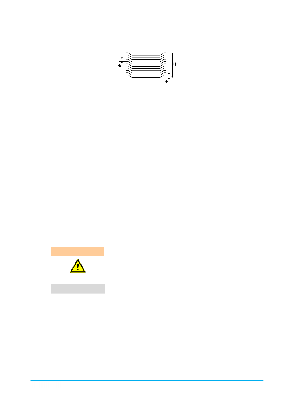
Figur
e 18 Intermediate stack height Hz of 11 crockery items
Example:
HZ =
K =
10
44.0
1.
1 - 5.51
= 0.44
1.16.24
+1 = 54
items
H1
=
1.1 in: Height of the first crockery item
H11
=
5.51 in: Height of 11 crockery items
t
=
11: Number of crockery items
HS
=
24.6 in: Stack height
So, 54 crockery items can be stacked into this dispensing tube.
5.3 Operation
Be
fore the appliance is put into operation it must be clean and dry.
Before work starts, it is always necessary to check whether the plate dispenser to be operated is correctly
set for the crockery to be used.
The vertical guide of the plates must be ensured, in order to prevent any risk of injury to the operating
staff if the crockery guides are set too far apart or too close together.
The correct dispensing height must be ensured, so that the staff cannot suffer injury or become trap-
ped and no breakage of crockery can occur.
Use of the cover
AT
TENTION Risk of injury
NO
Al
l the covers are provided with a 3-point locking mechanism.
Place the cover on to the dispensing tube and lock it by turning it clockwise.
Open the cover again by turning it anti-clockwise.
When using the plate dispenser with two dispensing tubes, a cover that have been removed previously can
be placed on to the second cover of the dispensing tube next to it.
If a
stack of plates with the covers is too high, do not push it down forcibly.
There is a risk of injury, if the locking is released.
TE Use of the cover
Th
e cover ensures effective protection against ingress of dust and condensed
water even during relatively long periods of temporary storage. Using the
cover in the heated appliances lowers the heat loss upwards and reduces the
heating time of the inserted crockery or delays the cooling of pre warmed
crockery.
Plate dispenser
4330000_A1 TE-2/V19-26, 27-33 | TE-2/VK19-26 | TEH-1/V19-26, 27-33 | TEH-2/V19-26, 27-33 | TEUH-1/VS19-26 | TEUH-2/VS19-26, 27-33 | TEUH-2/VC19-26
EBR/V19-26, 27-33 | EBRH/V19-26, 27-33 | EBRH-2/V19-26

Ch
apter 5 Operation
Page 32 Operation
5.
3.1 Switching on the appliance
CAUT
ION Hazardous electrical voltage
Th
e electrical voltage may be considerably dangerous to limb and life of per-
sons and lead to injuries.
Only use the plug connection provided for this. The appliance should not be
operated with a damaged connecting line or other visible damages.
All work on the electrical installations should only be carried out by a certified
electrician or by authorised specialists under supervision and monitoring of a
certified electrician according to the electro-technical regulations.
NO
TE Heated appliances
So
me parts of this section relate exclusively to the heated appliances and do
not apply to the unheated models.
Co
ver all the dispensing tubes with the covers to avoid heat loss.
Insert the mains plug into a suitable socket.
Switch on the appliance with the On / Off switch. The indicator integrated in the switch will light up to
show that the appliance is ready for operation.
Set the desired temperature using the thermostat. A continuous adjustment is possible within the 4
power ranges.
NO
TE Crockery temperature
5.
3.2 Loading the appliance
NO
TE Loading
NO
TE Warm-keeping items
De
pending upon the number and arrangement of the crockery stacks, the
required temperature of the crockery with the cover on and an initial crockery
temperature of at least 59 °F will be reached after 2 to 3 hours.
Be
fore the crockery items are inserted, the crockery guide and the stack
height must be set correctly.
Insert the items individually or in small safely manageable stacks.
Me
tal-coated warm-keeping items filled with wax can also be heated up wrong
in the most powerful plate dispenser.
The plate dispenser's performance is not sufficient to melt the wax within the
metallic sheath. As a result, liquid-to-solid phase transition cannot take place
during heat emission, so that the warm-keeping function of the warm-keeping
items is drastically reduced.
Plate dispenser
TE-2/V19-26, 27-33 | TE-2/VK19-26 | TEH-1/V19-26, 27-33 | TEH-2/V19-26, 27-33 | TEUH-1/VS19-26 | TEUH-2/VS19-26, 27-33 | TEUH-2/VC19-26
EBR/V19-26, 27-33 | EBRH/V19-26, 27-33 | EBRH-2/V19-26 4330000_A1

Op
eration Chapter 5
Operation Page 33
Loading
crockery
AT
TENTION Breakage of crockery
Th
e maximum loading height of the crockery baskets must be about 0.12'' to
0.20'' below the upper rim, otherwise this can cause breakage of crockery.
Do not stack the crockery items into the crockery baskets up to the upper
edge of the crockery basket.
Pl
ace the first plates on the centre of the guide basket and lower them slowly.
Place the further plates precisely onto the plates already positioned in the appliance.
The maximum filling level is achieved, when the guide basket does not lower anymore while loading
further plates.
If no cover is used, the uppermost plate should not protrude more than 2.36'' above the upper rim of
the housing.
NO
TE Filling level
A h
igher filling level is possible in the appliances used with the covers. Depending on the inherent stability of the items, they can be stacked up to the
lower edge of the cover. However, in the heated models the crockery items
resting above the upper rim of the appliance cannot be heated to the required
temperature.
The crockery with the cover should not protrude more than 5.12''. Even when
stationary, the plate dispenser must never be loaded beyond the permitted
maximum value of 5.12''.
Un
loading crockery
WA
RNING Risk of burning
Re
move the cover and put it down.
Take out the plates.
Put the cover back on.
NO
TE Appliances with cooling slots
In the hea
ted appliances the crockery temperatures can exceed the permitted
maximum temperatures of 149°F for touchable appliance surfaces.
Never reach into the appliance or touch the heating element with the fingers
during the operation.
Always wear protective gloves when dispensing hot crockery.
Th
e appliances are intended to provide cooled crockery. For this purpose, the
loaded appliances must remain in cold stores for several hours. The duration
of cooling depends on the initial crockery temperature, the temperature of the
cold store and the desired crockery temperature. The appliances must always
be free-standing in the room so that optimum air circulation is ensured by free
convection within and around the appliances.
Plate dispenser
4330000_A1 TE-2/V19-26, 27-33 | TE-2/VK19-26 | TEH-1/V19-26, 27-33 | TEH-2/V19-26, 27-33 | TEUH-1/VS19-26 | TEUH-2/VS19-26, 27-33 | TEUH-2/VC19-26
EBR/V19-26, 27-33 | EBRH/V19-26, 27-33 | EBRH-2/V19-26

Ch
apter 5 Operation
Page 34 Measures at the End of the Operation
5.
3.3 Moving the appliance
Turn off the thermostat.
Switch off the appliance with the On / Off switch.
Pull out the mains plug and insert it into the plug park provided.
Release both total brakes.
Grip the appliance by the push bars and move it to the destination.
At the destination, apply both total brakes in order to secure the appliance against movement.
Insert the mains plug into a suitable earthed socket.
Switch on the appliance with the On / Off switch.
Set the desired temperature using the thermostat.
5.4 Measures at the End of the Operation
WA
Mo
bile appliances
RNING Risk of hot surfaces
Th
e internal surfaces of the appliance and the base plates can become hot
during operation and only cool down slowly in the air.
For cleaning, allow the appliance to cool down sufficiently with the cover re-
moved and wear suitable protective gloves.
At the destination, apply both total brakes in order to secure the appliance against movement.
Turn off the thermostat.
Switch off the appliance with the On / Off switch.
Pull out the mains plug and insert it into the plug park provided.
Built-in appliances
Switch off the appliance with the On / Off switch.
Plate dispenser
TE-2/V19-26, 27-33 | TE-2/VK19-26 | TEH-1/V19-26, 27-33 | TEH-2/V19-26, 27-33 | TEUH-1/VS19-26 | TEUH-2/VS19-26, 27-33 | TEUH-2/VC19-26
EBR/V19-26, 27-33 | EBRH/V19-26, 27-33 | EBRH-2/V19-26 4330000_A1

Faul
t Detection and Trouble Shooting Chapter 6
Security Measures Page 35
6 Fa
6.
1 Security Measures
ult Detection and Trouble Shooting
CAUT
ION Hazardous electrical voltage
Th
sons and lead to injuries.
Before looking for faults, switch off the appliance at the mains. Pull out the
mains plug and insert it into the plug park provided.
6.
2 Notes on Trouble Shooting
Pl
ease check first whether there is an operating fault. You can eliminate some faults on your own.
Service work should only be carried out by authorised specialist staff.
Defective components should only be replaced with original parts.
In the event of after-sales service and when ordering spare parts specify the data given in the rating plate.
Inspection and maintenance intervals depend on the use of the appliance. Consult your dealer's after-sales
service department.
Regular inspection and maintenance of the appliance prevent disruptions to operation and ensure safety.
e electrical voltage may be considerably dangerous to limb and life of per-
6.3 Fault and Action Table
Fa
ult
Ap
pliance does not become warm;
F
in
dicator light does not come on.
a
Ap
pliance does not become warm;
u
in
dicator light does not come on.
l
t
Ap
pliance does not become warm;
G
in
dicator light does not come on.
e
r
Ap
pliance does not become warm;
in
dicator light is on.
Ap
pliance becomes warm; indicator
lig
ht does not come on.
Ap
pliance becomes warm; indicator
lig
ht does not come on.
Gu
ide basket does not move plates
upw
ards to the dispensing height
ev
en with a low load
To
tal brakes do not have any locking
ac
tion
Po
ssible cause
De
fective building fuses.
De
fective On / Off switch.
De
fective connecting cable or mains
pl
ug
Th
ermostat is defective.
De
fective indicator light.
De
fective On / Off switch.
Sp
ring breakage
To
tal brakes are worn
Ac
tion
Ch
eck fuse and repair, if necessary.
Sw
itch off the appliance at the mains
and
have it checked and repaired by
aut
horised specialist staff, if neces-
sa
ry.
Sw
itch off the appliance at the mains
and
have it checked and repaired by
aut
horised specialist staff, if neces-
sa
ry.
Ta
ke the appliance out of operation
and
have it checked and repaired by
aut
horised specialist staff, if neces-
sa
ry.
Ta
ke the appliance out of operation
and
have it checked and repaired by
aut
horised specialist staff, if neces-
sa
ry.
Ta
ke the appliance out of operation
and
have it checked and repaired by
aut
horised specialist staff, if neces-
sa
ry.
Re
place defective springs by new
ones
Ei
ther renew the locking brakes or
repl
ace the defective casters
Plate dispenser
4330000_A1 TE-2/V19-26, 27-33 | TE-2/VK19-26 | TEH-1/V19-26, 27-33 | TEH-2/V19-26, 27-33 | TEUH-1/VS19-26 | TEUH-2/VS19-26, 27-33 | TEUH-2/VC19-26
EBR/V19-26, 27-33 | EBRH/V19-26, 27-33 | EBRH-2/V19-26

Ch
apter 7 Cleaning and Care
Page 36 Security Measures
7 Cl
7.
1 Security Measures
eaning and Care
CAUT
ION Hazardous electrical voltage
WA
RNING Risk of hot surfaces
AT
TENTION Do not clean with running water
Th
e electrical voltage may be considerably dangerous to limb and life of per-
sons and lead to injuries.
Before cleaning, switch off the appliance at the mains. Pull out the mains plug
and insert it into the plug park provided.
Th
e internal surfaces of the appliance and the base plates can become hot
during operation and only cool down slowly in the air.
For cleaning, allow the appliance to cool down with the covers removed and
wear suitable protective gloves.
Th
e appliance should not be cleaned with running water, steam-jet or highpressure washers. The appliance must be taken out of operation and
switched off at the mains beforehand in any area where steam-jet or highpressure washers are to be used.
7.
2 Hygiene Measures
Th
e correct behaviour of the operating staff is decisive for optimal hygiene.
All persons must be informed about the locally valid hygiene regulations, observe them and comply with
them.
Stick a waterproof plaster to cover wounds on the hands and arms.
Never sneeze or cough on clean crockery.
7.3 Cleaning and Care
Th
e appliance must be cleaned dry daily or wiped with a damp cloth. Dry well the appliance after carrying out
wet cleaning, in order to prevent the development of mould, uncontrolled growth of germs and bacteria and,
consequently, contamination of the crockery.
All the plate dispensers (except TEUH-2/VC) have a base outlet located below the dispensing tubes that is
provided for the removal of broken crockery or other objects, which have accidentally fallen down into the
appliance. The objects that have fallen down into the enclosed dispenser can be removed by means of a
vacuum cleaner or gripping tongs.
The plastic covers can be cleaned manually with a damp cloth. In the case of solid impurities, appliances can
also be cleaned in a commercial dishwasher. Washing and rinsing agents suitable for polycarbonate should
be used.
Plate dispenser
TE-2/V19-26, 27-33 | TE-2/VK19-26 | TEH-1/V19-26, 27-33 | TEH-2/V19-26, 27-33 | TEUH-1/VS19-26 | TEUH-2/VS19-26, 27-33 | TEUH-2/VC19-26
EBR/V19-26, 27-33 | EBRH/V19-26, 27-33 | EBRH-2/V19-26 4330000_A1

Cl
eaning and Care Chapter 7
Special Care Instructions Page 37
7.
4 Special Care Instructions
Th
e resistance to corrosion of stainless steels is based on a passive layer which is formed on the surface
when oxygen is admitted. The oxygen in the air is sufficient for the formation of the passive layer, so that
faults or damage to the passive layer can be remedied again automatically by mechanical action.
The passive layer develops or reforms more quickly when the steel comes into contact with flowing water
containing oxygen. The passive layer can be chemically damaged or disrupted by agents having a reducing
(oxygen-consuming) action when the steel comes into contact with them in concentrated form or at high
temperatures.
Such aggressive substances are for example:
substances containing salt and sulphur
chlorides (salts)
seasoning concentrates (e.g. mustard, vinegar essence, seasoning cubes, saline solutions)
Further damages can occur due to:
extraneous rust (e.g. from other components, tools or rust film)
iron particles (e.g. grinding dust)
contact with non-ferrous metals (element formation)
lack of oxygen (e.g. no admission of air, low-oxygen water).
General working principles for the handling of appliances made from "refined stainless steel":
Always keep the surface of appliances made from stainless steel clean and accessible to the air.
Use cleaning agents suitable for stainless steel. No bleaching and chloride-containing cleaning a-
gents should be used.
Remove layers of lime scale, grease, starch and egg-white daily by cleaning. Corrosion can occur
underneath these layers due to lack of air admission.
After each cleaning operation remove all cleaning agent residues by rinsing thoroughly with copious
fresh water. Afterwards the surface should be thoroughly dried.
Do not bring parts made from stainless steel into contact with concentrated acids, seasonings, salts
etc. for longer than is absolutely necessary. Acid fumes which generate during cleaning of tiles also
promote the corrosion of "refined stainless steel".
Avoid damaging the surface of the stainless steel, particularly by metals other than stainless steel.
Residues of extraneous metals produce extremely small amounts of chemical elements which can
cause corrosion. In any case, contact with iron and steel should be avoided because that leads to extraneous rust. If stainless steel comes into contact with iron (steel wool, steel particles from pipes, water containing iron), this can be a trigger for corrosion. Therefore, for mechanical cleaning use exclusively refined steel wool or brushes with natural, plastics or refined steel bristles. Steel wool or
brushes with unalloyed steel lead to extraneous rust due to abrasion.
Plate dispenser
4330000_A1 TE-2/V19-26, 27-33 | TE-2/VK19-26 | TEH-1/V19-26, 27-33 | TEH-2/V19-26, 27-33 | TEUH-1/VS19-26 | TEUH-2/VS19-26, 27-33 | TEUH-2/VC19-26
EBR/V19-26, 27-33 | EBRH/V19-26, 27-33 | EBRH-2/V19-26

Ch
apter 8 Replacement Parts and Accessories
Page 38 Introduction
8 Repl
8.
1 Introduction
Se
acement Parts and Accessories
rvice work should only be carried out by authorised specialist staff.
Defective components should only be replaced with original parts.
In the event of after-sales service and when ordering spare parts specify always the data and corresponding
part number given in the rating plate.
8.2 Spare Parts and Accessories List
TE-2/
V19-26 | TE-2/V27-33 | TE-2/VK19-26
Sp
are part, part number
014000402 Sw
T
014000401 Sw
E
H
014002058 Hu
-
1
014002101 Pu
V
014002110 Co
1
9
014003210 Ca
-
014003211 Mu
2
6
014026004 Pl
014040101 Te
|
014040102 Te
T
E
014318000 Gu
H
on
request
-
1
0191092186 Cro
V
0162200 Tr
2
7
0162201 Tr
-
0162202 Tr
3
3
| TEH-2V19-26 | TEH-2V27-33
Ite
m designation
ivel caster with t otal brake
ivel caster
pfer logo
sh bar
rner bumpers
ge nuts
shroom-head screws
ugs
nsion springs
nsion springs
ide basket
Gu
ide basket
ckery guide
ansparent cover
ansparent cover
ansparent cover
Mo
del
125
mm (4.92''), screw plate
125
mm (4.92''), screw plate
stu
ck
0191010963,
M5
M5-R-083-11
M5
x10 A2
10
mm (0.39''), black, for corner bumpers
Sta
inless steel, 10g (0.35oz )
Sta
inless steel, 5g (0.18oz)
fo
r plate dispenser 19-26, coated steel, silver-grey
fo
r plate dispenser 27-33, coated steel, silver-grey
co
ated, complete
Po
lycarbonate, 19-26 (7.48''-10.24''), flat design
Po
lycarbonate, 19-26 (7.48''-10.24''), high design
Po
lycarbonate, 26-33 (10.63’’-13''), flat design
right and left
Q-ty
Sp
are part, part number
014000402 Sw
014000401 Sw
014001081 Cu
0191082883 Cu
014001300 On
014002058 Hu
014002101 Pu
014002110 Co
014002170-01 Th
0191148605 Du
014003210 Ca
Plate dispenser
TE-2/V19-26, 27-33 | TE-2/VK19-26 | TEH-1/V19-26, 27-33 | TEH-2/V19-26, 27-33 | TEUH-1/VS19-26 | TEUH-2/VS19-26, 27-33 | TEUH-2/VC19-26
EBR/V19-26, 27-33 | EBRH/V19-26, 27-33 | EBRH-2/V19-26 4330000_A1
Ite
m designation
ivel caster with total brake
ivel caster
rly cable
rly cable
/ Off switch
pfer logo
sh bar
rner bumpers
ermostat switch module
mmy plug socket
ge nuts
Mo
del
125
mm (4.92''), screw plate
125
mm (4.92''), screw plate
3
x 1.0 m (3.28’) with Schuko® angle plug
3
x 1.5 (4.92’) with Schuko® angle plug
stu
ck
0191010963,
co
mplete
Sc
huko®, complete
M5
M5-R-083-11
right and left
Q-ty

Re
placement Parts and Accessories Chapter 8
Spare Parts and Accessories List Page 39
Sp
are part, part number
014003211 Mu
014026004 Pl
014040011-01 Th
014040068 He
014040101 Te
014040102 Te
014318000 Gu
on
request
0191092186 Cro
0162201 Tr
0162202 Tr
Ite
m designation
shroom-head screws
ugs
ermostat
ating element
nsion springs
nsion springs
ide basket
Gu
ide basket
ckery guide
ansparent cover
ansparent cover
TE
UH-1/VS19-26 | TEUH-2/VS19-26
Sp
are part, part number
014000402 Sw
014000401 Sw
014001081 Cu
0191082883 Cu
014001300 On
014002058 Hu
014002101 Pu
014002110 Co
014002170-01 Th
0191148605 Du
014002951 O-ri
014003210 Ca
014003211 Mu
014026004 Pl
014040011-01 Th
014001107 He
014040101 Te
014040102 Te
014318000 Gu
on
request
0191092186 Cro
0162201 Tr
014001013 Ho
0191095077 Sa
Ite
m designation
ivel caster with total brake
ivel caster
rly cable
rly cable
/ Off switch
pfer logo
sh bar
rner bumpers
ermostat switch module
mmy plug socket
ng
ge nuts
shroom-head screws
ugs
ermostat
ating element
nsion springs
nsion springs
ide basket
Gu
ide basket
ckery guide
ansparent cover
t air fan
fety temperature limiter
Mo
del
M5
x10 A2
10
mm (0.39''), black, for corner bumpers
30-115°C
230V
Sta
Sta
fo
fo
co
Po
Po
Mo
125
125
3
3
stu
0191010963,
co
Sc
fo
M5
M5
10
30-115°C
230V
Sta
Sta
fo
fo
co
Po
(86-239°F)
- 900W, static
inless steel, 10g (0.35oz)
inless steel, 5g (0.18oz)
r plate dispenser 19-26, coated steel, silver-grey
r plate dispenser 27-33, coated steel, silver-grey
ated, complete
lycarbonate, 19-26 (7.48''-10.24''), high design
lycarbonate, 27-33 (10.63-13''), flat design
del
mm (4.92''), screw plate
mm (4.92''), screw plate
x 1.0 m (3.28’) with Schuko® angle plug
x 1.5 (4.92’) with Schuko® angle plug
ck
right and left
mplete
huko®, complete
r switch plate
M5-R-083-11
x10 A2
mm (0.39''), black, for corner bumpers
(86-239°F)
– 1500W, circulating air
inless steel, 10g (0.35oz)
inless steel, 5g (0.18oz)
r plate dispenser 19-26, coated steel, silver-grey
r plate dispenser 27-33, coated steel, silver-grey
ated, complete
lycarbonate, 19-26 (7.48''-10.24''), high design
Q-ty
Q-ty
Plate dispenser
4330000_A1 TE-2/V19-26, 27-33 | TE-2/VK19-26 | TEH-1/V19-26, 27-33 | TEH-2/V19-26, 27-33 | TEUH-1/VS19-26 | TEUH-2/VS19-26, 27-33 | TEUH-2/VC19-26
EBR/V19-26, 27-33 | EBRH/V19-26, 27-33 | EBRH-2/V19-26

Ch
apter 8 Replacement Parts and Accessories
Page 40 Spare Parts and Accessories List
TE
UH-2/VC 19-26
Sp
are part, part number
014000402 Sw
014000401 Sw
0191082883 Cu
014001300 On
014002058 Hu
014002101 Pu
014002110 Co
014002170-01 Th
0191148605 Du
014003210 Ca
014003211 Mu
014026004 Pl
014040228-01 Th
014041047-03 He
014040101 Te
014040102 Te
014318002 Gu
014319003 Cro
0162200 Tr
014001013 Ho
0191095077 Sa
EBR
/V19-26 | EBR/V27-33
Ite
m designation
ivel caster with total brake
ivel caster
rly cable
/ Off switch
pfer logo
sh bar
rner bumpers
ermostat switch module
mmy plug socket
ge nuts
shroom-head screws
ugs
ermostat
ating element
nsion springs
nsion springs
ide basket
ckery guide
ansparent cover
t air fan
fety temperature limiter
Mo
del
125
mm (4.92''), screw plate
125
mm (4.92''), screw plate
3
x 1.5 (4.92’) with Schuko® angle plug
stu
ck
0191010963,
co
mplete
Sc
huko®, complete
M5
M5-R-083-11
M5x
10 A2
10
mm (0.39''), black, for corner bumpers
20-130 °C
230 – 2
Sta
inless steel, 10g (0.35oz)
Sta
inless steel, 5g (0.18oz)
Sta
inless steel, electro polished, with guide rollers
Sta
inless steel, uncoated, complete
Po
lycarbonate, 19-26 (7.48''-10.24''), flat design
right and left
(68-266°F)
000W, circulating air
Q-ty
Sp
are part, part number
014040101 Te
014040102 Te
0191004816 Co
014322000 Co
014318000 Gu
0191002254 Cro
Ite
m designation
nsion springs
nsion springs
ver
ver
ide basket
ckery guide
EBR
H/V19-26 | EBRH/V27-33 |EBRH-2/V19-26
Sp
are part, part number
014040101 Te
014040102 Te
0191004816 Co
014322000 Co
014318000 Gu
0191002254 Cro
014128901 Co
Item
designation
nsion springs
nsion springs
ver
ver
ide basket
ckery guide
nnecting cable set
Mo
del
Sta
inless steel, 10g (0.35oz)
Sta
inless steel, 5g (0.18oz)
Pl
astic, high design
fo
r plate dispenser 19-26, coated steel, silver-grey
co
ated, complete
Mo
del
Sta
inless steel, 10g (0.35oz)
Sta
inless steel, 5g (0.18oz)
Pl
astic, high design
fo
r plate dispenser 19-26, coated steel, silver-grey
co
ated, complete
Q-ty
Q-ty
Plate dispenser
TE-2/V19-26, 27-33 | TE-2/VK19-26 | TEH-1/V19-26, 27-33 | TEH-2/V19-26, 27-33 | TEUH-1/VS19-26 | TEUH-2/VS19-26, 27-33 | TEUH-2/VC19-26
EBR/V19-26, 27-33 | EBRH/V19-26, 27-33 | EBRH-2/V19-26 4330000_A1

Re
placement Parts and Accessories Chapter 8
Spare Parts and Accessories List Page 41
Sp
are part, part number
0191009066 Gu
014318000 Gu
014318000 Gu
014326076 He
0191008152 He
019101879 He
014510023 He
4510022 Pl
014001202 Te
014001214-02 Th
014040011-01 Th
Item
designation
ide basket
ide basket
ide basket
at cassette
at cassette
ating element
ating element
ug
mperature limiter
ermostat
ermostat
Mo
del
19-26
27-33
19-26,
coated steel, silver-grey
EBR
H/V19-26 and EBRH/V27-33 only
EBR
H/-2V19-26 only
230V
– 200W, EBRH/V19-26 and EBRH/V27-33
onl
y
230V
– 500W, EBRH-2/V19-26 only
20-85°C
(68-185°F), EBRH/V19-26 and EBRH/V27-
33
only
30-115°C
(86-239°F), EBRH-2/V19-26 only
Th
e following types of plug can be used with the plate dispensers:
2-pole Schuko® angle plug (standard).
3-pole British mains plug in accordance with BS 1363 A for Great Britain and Hong Kong
3-pole Swiss mains plug of type 12 - 10 A
n-1
Q-ty
Plate dispenser
4330000_A1 TE-2/V19-26, 27-33 | TE-2/VK19-26 | TEH-1/V19-26, 27-33 | TEH-2/V19-26, 27-33 | TEUH-1/VS19-26 | TEUH-2/VS19-26, 27-33 | TEUH-2/VC19-26
EBR/V19-26, 27-33 | EBRH/V19-26, 27-33 | EBRH-2/V19-26
 Loading...