

Hupfer OTA/47-36, OTA/58-33, OTA/53-37 S, OTA/53-37, OTA/U-BW Operating Instructions Manual
...
Operating Instructions
Tray dispenser
OTA/47–36 | OTA/53–37 | OTA/58-33 | OTA/53–37 S | OTA/U-
BW | OTA-E/BA-4xGN | TAG-1/53-37 | TA-2/53-37 | EBS-T/53-37
4330041_A0

Chapter 1 Introduction
Page 2 Appliance Information
1 Introduction
1.1 Appliance Information
Appliance designation Tray dispenser
Appliance type/ -s OTA/47–36 | OTA/53–37 | OTA/58-33 | OTA/53–37 S |
OTA/U-BW | OTA-E/BA-4xGN | TAG-1/53-37 | TA-2/5337 | EBS-T/53-37
Manufacturer HUPFER® Metallwerke GmbH & Co. KG
Dieselstraße 20
48653 Coesfeld
PO 1463
48634 Coesfeld
+49 2541 805-0
+49 2541 805-111
www.hupfer.de
info@hupfer.de
Tray dispenser
OTA/47–36 | OTA/53–37 | OTA/58-33 | OTA/53–37 S | OTA/U-BW | OTA-E/BA-4xGN | TAG-1/53-37 | TA-2/53-37 | EBS-T/53-37
Read these operating instructions thoroughly to ensure safe operation and avoid any damages before the
first operation.
Ensure that sources of danger and possible faulty operations have been pointed out to the operating staff.
Subject to modifications
The products covered by these operating instructions have been developed taking into consideration the requirements of the market and the latest technology. HUPFER
®
reserves the right to modify the products and
appertaining technical documentation in so far as the modifications are in the name of technological progress. The data and weights as well as the description of performance and functions assured in the order
confirmation as binding are always decisive.
Manual edition
4330041_A0
Tray dispenser
OTA/47–36 | OTA/53–37 | OTA/58- 33 | OTA/53–37 S | OTA/U-BW | OTA-E/BA-4xGN | TAG- 1/5 3- 37 | TA-2/ 53 -3 7 | EBS-T /53- 37
4330041_A0

Introduction Chapter 1
Table of Contents Page 3
1.2 Table of Contents
1 Introduction 2
1.1 Appliance Information 2
1.2 Table of Contents 3
1.3 List of Abbreviations 5
1.4 Definitions of Terms 6
1.5 Orientation Guide 7
1.6 Notes on Use of Manual 8
1.6.1 Notes on the manual structure 8
1.6.2 Notes and their illustrations used in the chapters 8
2 Safety Instructions 9
2.1 Introduction 9
2.2 Warning Symbols Used 9
2.3 Safety Instructions for Appliance Safety 9
2.3.1 Special safety instructions for mobile tray dispensers 10
2.3.2 Special safety instructions for open tray dispensers 10
2.3.3 Special safety instructions for clo sed tray dispen ser s 10
2.4 Safety Instructions for Cleaning and Care 10
2.5 Safety Instructions for Troubleshooting 10
3 Description and Technical Data 11
3.1 Performance Description 11
3.2 Intended Use 11
3.3 Improper Use 11
3.4 Appliance Description 12
3.4.1 View of the appliance 12
3.4.2 Appliance Description 14
3.4.3 Optional special accessories 14
3.5 Technical Data 15
3.6 Rating Plate 18
4 Transport, Putting into Operation, Assembly and Decommissioning 19
4.1 Transport 19
4.2 Assembly (EBS-T/53-37 only) 19
4.3 Putting into Operation 20
4.4 Storage and Recycling 21
5 Operation 22
5.1 Adjustment of the closed tray dispensers 22
5.1.1 Adjust springs 22
5.2 Adjustment of the open tray dispensers 23
5.2.1 Adjust the model OTA/S 23
5.2.2 Adjustments OTA/U-BW 24
5.2.3 Adjust springs 26
Tray dispenser
4330041_A0 OTA/47–36 | OTA/53– 37 | OTA/5 8- 33 | OTA /53 –3 7 S | OTA/U-BW | OTA-E/BA-4xGN | TAG-1/53-37 | TA-2/ 53 -3 7 | EBS -T/53- 37

Chapter 1 Introduction
Page 4 Table of Contents
5.3 Calculating the capacity for trays 28
5.4 Operation 29
6 Fault Detection and Troubleshooting 30
6.1 Notes on Troubleshooting 30
6.2 Fault and Action Table 30
7 Cleaning and Care 31
7.1 Security Measures 31
7.2 Hygiene Measures 31
7.3 Cleaning and Care 31
7.4 Special Care Instructions 31
8 Spare Parts and Accessories 33
8.1 Introduction 33
8.2 Spare Parts and Accessories List 33
Tray dispenser
OTA/47–36 | OTA/53–37 | OTA/58- 33 | OTA/53–37 S | OTA/U-BW | OTA-E/BA-4xGN | TAG- 1/5 3- 37 | TA-2/ 53 -3 7 | EBS-T /53- 37
4330041_A0

Introduction Chapter 1
List of Abbreviations Page 5
1.3 List of Abbreviations
Abbreviation Definition
BGR Rule of the Professional Association
BGV Regulati on of t he Prof essi onal Assoc i ation
CE Communauté Européenee
European Community
DIN Deutsches Institut für Normung
German Institute for Standardisation, technical regulations and technical specifications
EC European Community
European Union
EN European Standard
Harmonised standard for the EU market
E/V Spare and wearing part
IP International Protection. The abbreviation IP and a furt her two-digit index specif y t he
LED Light Emitting Diode
RCE Residual current device (RCD) In the EU the English RCD (Residual Current Device)
protection class of a housing.
The first digit: Protection against ingress of solid foreign objects The second digit: Protection against ingress of
water
0 No protection against contact, no protec-
tion against ingress of solid foreign
objects
1 Protection against contact with any large
surface of the body such as the hand,
protection against ingress of foreign
objects >1.97'' (50 mm )
2 Protection against contact with the
fingers, protection against ingress of
foreign objects ҏ!PP
3 Protection against contact with tools,
thick wires or similar objects of ҏ!
(2.5 mm) protection against foreign
objects ҏ!PP
4 Protection against contact with tools,
thick wires or similar objec ts of ҏ!
(1 mm) protection against foreign objects
ҏ!PP
5 Protection against contact, protection
against dust deposits inside
6 Complete protection against contact,
protection against ingress of dust
7 Protection against ingress of water
8 Protection against pressurised water
0 No protection against ingress of water
1 Protection against vertically falling water
drops
2 Protection against dripping water (at any
angle up to 15° from the vertical)
3 Protection against water drips at any
angle up to 60° from the vertical
4 Protection against water splashing from
any direction
5 Protection against water jets (projected
by a nozzle) at any angle
6 Protection against rough sea or strong
water jets (flood protection)
during temporary imm ersi on
during continuous imm ersio n
Light diode
term is customary in standardisation matters.
Tray dispenser
4330041_A0 OTA/47–36 | OTA/53– 37 | OTA/5 8- 33 | OTA /53 –3 7 S | OTA/U-BW | OTA-E/BA-4xGN | TAG-1/53-37 | TA-2/ 53 -3 7 | EBS -T/53- 37

Chapter 1 Introduction
Page 6 Definitions of Terms
1.4 Definitions of Terms
Term Definition
Authorised specialist An authorised specialist is a specialist that has been trained by the manufacturer, an
Cook&Chill-Kitchens "Cook and Chill": Kitchens where warm food after being cooked is chilled as quickly as
Cook&Serve-Kitchens "Cook and Serve": Kitchens where warm food is served immediately after being
Element formation Also: contact corrosion. Occurs when different noble metals are in close cont act with
EN tray A European standard tray is a tray with a standard size.
Specialist A specialist is a person who can evaluate work assigned and can individually recog-
Gastronorm Gastronorm is a measurement system applied worldwide, for instance, in food proc-
GN tray A gastronorm tray is a tray with a standard size.
Lift A movement, for example a vertical movement of the stacking platform from bottom to
Control Compare with certain conditions and/or characteristics such as damages, leaks, filling
Convection Physical properties or mass transfer (e.g. heat or cold) through currents in gases and
Corrosion The chemical reaction of a metallic material with its surroundings, e.g. rust.
Machine safety The term of machine safety means all the measures used to avert injury to persons.
Passive layer A non-metallic protective layer on a metallic material that prevents or slows down
Check Compare with certain values such as weight, torque, content, temperature.
Qualified person,
qualified staff
Schuko® The abbreviation of the German term "Protective contact" that indicates a system of
Instructed persons An instructed person is a person who has been instructed on the possible risks result-
authorised service dealer or a company assigned by the manufacturer.
possible.
cooked or kept warm until it is consumed.
each other. This happens when a corrosive medium is between both metals, as for
example water or even air humidity.
EN 1/1 corresponds to 20.87×14.57’’ (530×370 mm), EN 1/2 corresponds to
14.57×10.43’’ (370×265 mm).
nise any possible dangers due to the professional training, specialist knowledge and
experience as well as knowledge of the respective guidelines.
essing plants or large-scale kitchens . The use of standardised sizes makes possible
to exchange food pans. The basic size of the gastronorm (GN) 1/1 is 12.8×20.87''
(325×530mm). Items are available in different depths.
GN 1/1 corresponds to 20.87×12.8’’ (530×325 mm), GN 1/2 corresponds to
12.8×10.43’’ (325×265 mm).
top.
levels, heat.
liquids.
The basis for this are national as well as EC-wide valid directives and laws for protecting users of technical devices and systems.
material corrosion.
Qualified personnel are persons who due to their professional training, experience and
instruction as well as their knowledge of the respective standards, guidelines, accident
prevention regulations and operating conditions have been authorised by a person
responsible for system safety to carry out required activities and can recognise and
prevent any possible danger (definition of specialists according to IEC 364).
domestic plugs and sockets equipped with protective earthed contacts used in most of
Europe.
ing from improper behaviour when carrying out the assigned task as well as on the
necessary protective equipment and protective measures and trained for this task if
necessary.
Tray dispenser
OTA/47–36 | OTA/53–37 | OTA/58- 33 | OTA/53–37 S | OTA/U-BW | OTA-E/BA-4xGN | TAG- 1/5 3- 37 | TA-2/ 53 -3 7 | EBS-T /53- 37
4330041_A0

Introduction Chapter 1
Orientation Guide Page 7
1.5 Orientation Guide
The front
The 'front' means the operating side.
Push bars are installed on the mobile tray dispensers to move the tray dispenser.
From the front of the cutlery and tray dispensers, the silverware attachments are available.
The side of the built-in appliance named as "the front" means the side, at which the staff operates the appliance.
The rear
The side named "the rear" means the opposite side of the front side (the front).
The right
The side named "the right" means the side at the right hand side of the front side (the front).
The left
The side named "the left" means the side at the left hand side of the front side (the front).
Tray dispenser
4330041_A0 OTA/47–36 | OTA/53– 37 | OTA/5 8- 33 | OTA /53 –3 7 S | OTA/U-BW | OTA-E/BA-4xGN | TAG-1/53-37 | TA-2/ 53 -3 7 | EBS -T/53- 37
Chapter 1 Introduction
Page 8 Notes on Use of Manual
1.6 Notes on Use of Man ua l
1.6.1 Notes on the manual structure
This manual is structured in functional and task orientated chapters.
1.6.2 Notes and their illustrations used in the chapters
DANGER Brief description of danger
There is an imminent danger to life and limb of the user and / or third parties
when the instructions are not followed precisely or the circumstances de-
WARNING Brief description of danger
scribed are not taken into account.
The type of danger is indicated by a symbol and explained in the accompany-
ing text in more detail. In this example the general sign of danger is used.
There is an indirect danger to life and limb of the user and / or third parties
when the instructions are not followed precisely or the circumstances described are not taken into account.
The type of danger is indicated by a symbol and explained in the accompanying text in more detail. In this example the general sign of danger is used.
ATTENTION Brief description of danger
There is a potential risk of injury or damage to property when the instructions
are not followed precisely or the circumstances described are not taken into
account.
The type of danger is indicated by a general sign and explained in the accompanying text in more detail. In this example the general sign of danger is used.
NOTE Brief description of additional information
Attention is pointed to special conditions or additional important information on
the respective subject.
INFO Short title
Contains additional information on work assisting features or recommendations on the respective subject.
Tray dispenser
OTA/47–36 | OTA/53–37 | OTA/58- 33 | OTA/53–37 S | OTA/U-BW | OTA-E/BA-4xGN | TAG- 1/5 3- 37 | TA-2/ 53 -3 7 | EBS-T /53- 37
4330041_A0
Safety Instructions Chapter 2
Introduction Page 9
2 Safety Instructions
2.1 Introduction
The chapter on safety instructions describes the risks associated with the appliance in terms of product liability (according to the EU Directives).
The safety instructions should warn of hazards and help to avoid damages to persons, the environment and
property. Please make sure that you have read and understood all the safety instructions given in this chapter.
You must comply with the respectively valid national and international Safety at Work Regulations. The
manager is responsible for the valid regulations he/she has to provide. He/she must acquaint himself/herself
and the operator with the new regulations.
In addition to these operating instructions, comply with the rules on health and safety at work issued by the
Main Association of the industrial Professional Associations, especially with those that concern the handling
of hot items and risks involved (BGR 110 "Protection of health and safety at work in restaurants" and BGR
111 "Protection of health and safety at work in large-scale kitchens").
2.2 Warning Symbols Used
Symbols are used in these operating instructions to point out the dangers that can occur while operating or
cleaning the appliance. In both cases, the symbol provides information on the type and circumstances of
danger.
The following symbols can be used:
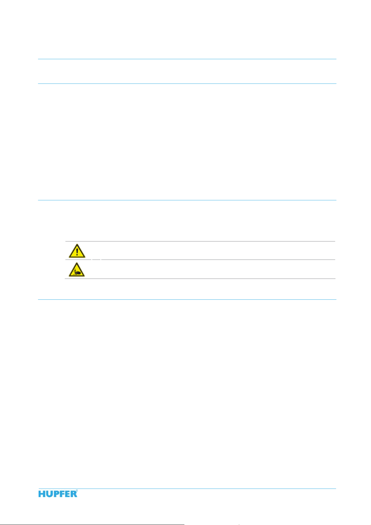
General hazardous area
Risk of hand injuries
2.3 Safety Instructions for Appliance Safety
Safe operation of the appliance depends on appropriate and thorough use. Negligent handling of the appliance can lead to danger to life and limb of the user and / or third parties as well as hazards to the appliance
itself and the other operator's property.
The following points are to be observed to ensure the appliance safety:
The appliance may only be operated when it is in perfect condition with regards to technical stan-
dards.
All the operating and actuating elements must be in a perfect and functionally reliable condition with
regards to technical standards.
Modifications or retrofits of the equipment are only permitted in consultation with the manufacturer
and on receipt of his written agreement.
In no case may people sit or stand on the appliance. Transport of persons is not permitted.
Before loading, the tray dispensing height at closed tray dispensers needs to be adjusted to the trays
used.
Never push the stacking platform down manually (e.g. for cleaning). There is a risk of injury when re-
leased.
Tray dispenser
4330041_A0 OTA/47–36 | OTA/53– 37 | OTA/5 8- 33 | OTA /53 –3 7 S | OTA/U-BW | OTA-E/BA-4xGN | TAG-1/53-37 | TA-2/ 53 -3 7 | EBS -T/53- 37

Chapter 2 Safety Instructions
Page 10 Safety Instructions for Cleaning and Care
2.3.1 Special safety instructions for mobile tray dispensers
The appliance is provided exclusively for manual transport. Transport using any kind of devi ces is not
permitted. Risk of injury and damage.
Release both total brakes before commencing transporting. Moving the appliance with the total
brakes lo cked can damage the chassis.
Transport should only be undertaken over level floors. Moving the appliance over very uneven floors
can damage the chassis.
Transport over inclined planes or steps is not permitted.
When approaching walls and moving round obstacles always pay attention to persons in the way.
Risk of injury.
When transporting the appliance, always hold both handles with your hands. Never let go of the ap-
pliance while moving it.
When transporting the appliance, do not move it faster than a walking pace. Heavily laden tray dis-
pensers are difficult to brake and steer. If necessary, ask for assistance when transporting the appliance.
If the tray dispenser tips over due to outside influences or inattention, never catch it manually. Risk of
injury.
Do not stop the appliance on sloping floors.
After stopping, the appliance should be secured against rolling away by means of both total brakes
being applied.
In the case of off-site transport in a vehicle such as a lorry, the appliances should be secured prop-
erly. The total brakes are not sufficient as a transport securing method.
2.3.2 Special safety instructions for open tray dispensers
The stacking platforms of the models OTA/47-36 and OTA/53-37 are not adjustable. Only suitable
tray sizes may be transported.
It is necessary to ensure that the stacking area of the models OTA/53-37 S and OTA/U-BW is always
adjusted to the dimensions of the trays to be transported.
The trays always have to be laid up within the edge on the stacking platform.
No items may be placed on the base plate when transporting.
The paths of the outrigger may not be blocked.
2.3.3 Special safety instructions for closed tray dispensers
To avoid injuries to the hands, care should always be taken to ensure that the dispensing height does
not fall below the upper rim of the housing.
2.4 Safety Instructions for Cleaning and Care
The following points shall be observed when carrying out any cleaning and maintenance operations:
For reasons of hygiene the cleaning instructions shall be strictly observed.
Do not clean the appliance with steam-jet or high-pressure washers.
2.5 Safety Instructions for Troubleshooting
The following points shall be observed when carry ing out any maintenance and troubleshooting operations:
All troubleshooting work should only be carried out by authorised specialists.
Defective components should only be replaced with original parts.
The local applicable Accident Prevention Regulations must be observed.
Tray dispenser
OTA/47–36 | OTA/53–37 | OTA/58- 33 | OTA/53–37 S | OTA/U-BW | OTA-E/BA-4xGN | TAG- 1/5 3- 37 | TA-2/ 53 -3 7 | EBS-T /53- 37
4330041_A0

Description and Technical Data Chapter 3
Performance Description Page 11
3 Description and Technical Data
3.1 Performance Description
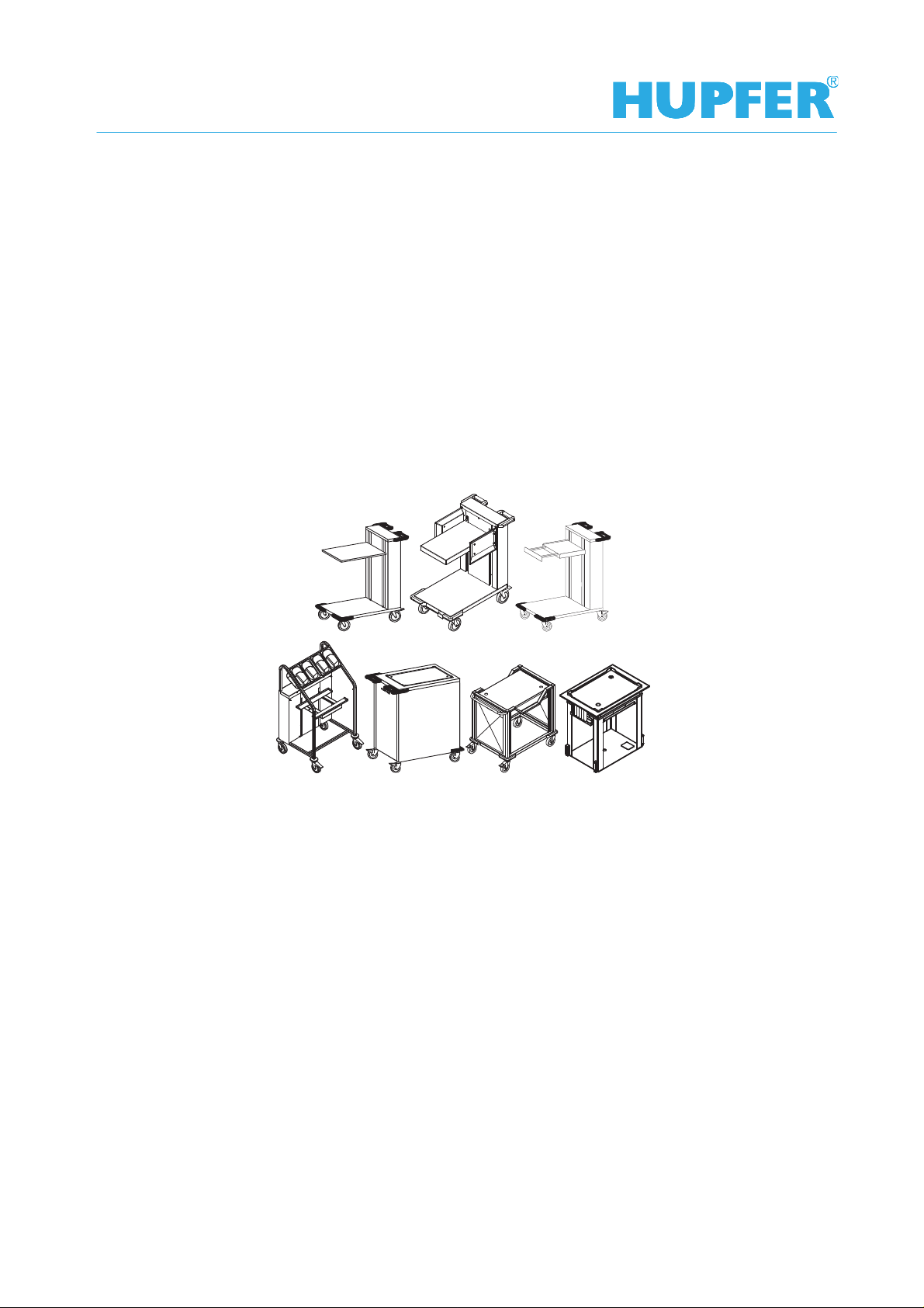
Tray dispensers are provided for the transport and storage of different trays in large-scale catering establishments and in the food service industry. If necessary, there are various models available:
Models of the type OTA are preferably used in areas of customer self-service counters, bistros and cafeterias. Furthermore, they can be used for the storage of trays on food distribution belts and in sculleries if there
is no automatic stacking.
Models of the type OTA/S are suitable for the stacking of trays at crockery return conveyors, also in connection with a stacking device. The trays are placed in the longitudinal direction and are held in place by the
sideways tray guide rails. The stacking area is adjustable in length and width to different tray dimensions.
Open basket dispensers of the type OTA/U-BW are suitable for the automatic stacking of trays in longitudinal
or transverse direction at dishwashers. The stacking area is adjustable in length and width to different tray
dimensions.
Models of the type OTA-E/BA-4xGN are also used in areas of customer self-service bars, bistros and cafeterias. They do not only provide trays but also cutlery in GN containers with sneeze guard.
Models of type TAG are closed tray dispensers for a stack of EN or GN trays. They are preferably used as a
tray dispenser in the guest area of cafeterias, canteens, rest houses and bistros used. In contrast to open
tray dispensers, the tray column is guided on all sides above the entire hei ght and can not b e overturn ed.
Due to the closed side walls, the tray dispenser can store trays of different colours and formats without disturbing the overall visual impression.
Models of the type TA are closed on the front side and are intended for two stacks of EN trays and GN trays.
Due to the high capacity, these models are ideal for the use on food distribution belts.
Besides the mobile tray dispensers, there is the model EBS-T intended for installation in worktops.
3.2 Intended Use
Tray dispensers are intended exclusively for transport and storage of trays ready for use.
Appliances of the type TAG have no compartment inner panelling. Therefore, universal trays, breakfast trays
and trapeze-shaped trays can not be inserted because of the smaller tray dimensions.
Appliances of the type TA are suitable only for EN and GN trays due to the half-open design. Other tray di-
mensions may not be used.
The intended use means the predetermined proc edures, compliance with the indicated spe cific ations and
use of the delivered or additionally available original accessories.
Any other use of the appliance is considered as unintended use.
3.3 Improper Use
It is not permitted to load the tray dispenser with other loads as given.
Tray dispensers are not intended to transport food.
In no case may people sit or stand on the appliance. Transport of persons is not permitte d.
No liability is assumed and no warranty claims can be submitted for damage s cau sed by improper use .
Tray dispenser
4330041_A0 OTA/47–36 | OTA/53– 37 | OTA/5 8- 33 | OTA /53 –3 7 S | OTA/U-BW | OTA-E/BA-4xGN | TAG-1/53-37 | TA-2/ 53 -3 7 | EBS -T/53- 37

Chapter 3 Descript ion and Technical Data
Page 12 Appliance Description
3.4 Appliance Description
3.4.1 View of the appliance
Figure 1 View of the appliance OTA
1 Cover of the spring case 6 Casters with total brakes
2 Stacking platf orm 7 Paths of the outrigger
3 Base plate 8 Spring case
4 Corner bumpers 9 Push bar
5 Casters without t otal brakes
Figure 2 View of the appliance OTA/S
1 Cover of the spring cas e 6 Casters with total brakes
2 Stacking platf orm 7 Paths of the outrigger
3 Base plate 8 Spring case
4 Corner bumpers 9 Sideways tray guide rail
5 Casters without total brakes 10 Push bar
Tray dispenser
OTA/47–36 | OTA/53–37 | OTA/58- 33 | OTA/53–37 S | OTA/U-BW | OTA-E/BA-4xGN | TAG- 1/5 3- 37 | TA-2/ 53 -3 7 | EBS-T /53- 37
4330041_A0

Description and Technical Data Chapter 3
Appliance Description Page 13
Figure 3 View of the appliance OTA/U-BW
1 Cover of the spring cas e 6 Casters with total brakes
2
Stacking platform with tray stop unit (in the front and sideways) 7 Paths of the outrigger
3 Base plate 8 Spring case
4 Corner bumpers 9 Push bar
5 Casters without t otal brakes
Figure 4 View of the appliance OTA-E/BA-4xGN
1 Cover of the spring cas e 6 Casters with total brakes
2 Spring case 7 Protection plate
3 Paths of the outrigger 8 Stacking platform
4 Panel for the spring case 9 Cutlery holder
5 Casters without total brakes 10 Sneeze guard
Tray dispenser
4330041_A0 OTA/47–36 | OTA/53– 37 | OTA/5 8- 33 | OTA /53 –3 7 S | OTA/U-BW | OTA-E/BA-4xGN | TAG-1/53-37 | TA-2/ 53 -3 7 | EBS -T/53- 37

Chapter 3 Description and Technical Data
Page 14 Appliance Description
3.4.2 Appliance Description
Tray dispensers are executed in the self-supporting construction of stainless steel.
They accommodate trays on a spring-loaded stacking platform. Owing to the use of special springs, trays are
moved automatically and constantly over the entire lift upwards to a uniform dispensing height.
The ergonomically formed push bars with integrated bumper protect the operating staff against damages to
the hands. Corner bumpers on the rear protect the appliance against damages when transporting it.
The stacking platform of the models TA, TAG and EBS-T is removable and makes it possible to adjust the
springs as well as to clean the appliance easily.
3.4.3 Optional special accessories
The following parts can be applied as optional accessories for the movable tray dispenser:
Casters made of corrosion-resistant and maintenance-free plastic with a thread protection, a precision
ball bearing, Ø 4.92’’ (125 mm) with and without the total brakes, plate attachment
Holder for dispensing napkins (for OTA E/BA-4xGN)
The part numbers of the special accessories can be found in the spare parts catalogue and order lists available online.
Tray dispenser
OTA/47–36 | OTA/53–37 | OTA/58- 33 | OTA/53–37 S | OTA/U-BW | OTA-E/BA-4xGN | TAG- 1/5 3- 37 | TA-2/ 53 -3 7 | EBS-T /53- 37
4330041_A0

Description and Technical Data Chapter 3
Technical Data Page 15
3.5 Technical Data
Dim. OTA/47-36 OTA/53-37 OTA/58-33
View of the appliance
Description Open tray dispenser Open tray dispenser Open tray dispenser
Own weight lbs
Payload lbs
Permitted total
weight
Overall dimensions
w x d x h
Chassis in
Stacking platform in
Stack height in
possible
tray dimensions
Length x Width
suitable
tray types
Capacity - trays per
stack
(kg)
(kg)
lbs
(kg)
in
(mm)
(mm)
(mm)
(mm)
in
(mm)
1 x Universal trays
120 120 120
105.8
(48)
264.6
(120)
370.4
(168)
20.28 x 30.5 x 35.43
(515 x 800 x 900)
4 swivel casters,
2 with total brakes,
4.92’’ (125)
18.9 x 14.57
(480 x 370)
Stainless steel
25.2
(640)
18.5 x 14.17
(470 x 360)
18.11 x 13.54’’
(460 x 344 mm)
105.8
(48)
264.6
(120)
370.4
(168)
20.28 x 30.5 x 35.43
(515 x 800 x 900)
4 swivel casters,
2 with total brakes,
4.92’’ (125)
21.26 x 14.96
(540 x 380)
Stainless steel
25.2
(640)
20.87 x 14.57
(530 x 370)
1 x EN trays
20.87×14.57’’
(530 x 370 mm)
1 x GN trays
20.87×12.8’’
(530 x 325 mm)
1 x Universal trays
18.11 x 13.54’’
(460 x 344 mm)
1 x Trapeze-shaped trays
18.9 x 13.78’’
(480 x 350 mm)
105.8
(48)
264.6
(120)
370.4
(168)
20.28 x 30.5 x 35.43
(515 x 800 x 900)
4 swivel casters,
2 with total brakes,
4.92’’ (125)
23.03 x 13.19
(585 x 335)
Stainless steel
25.2
(640)
22.64 x 12.8
(575 x 325)
1 x EN trays
20.87×14.57’’
(530 x 370 mm)
1 x GN trays
20.87×12.8’’
(530 x 325 mm)
1 x Universal trays
18.11 x 13.54’’
(460 x 344 mm)
1 x Trapeze-shaped trays
18.9 x 13.78’’
(480 x 350 mm)
2 x Breakfast trays
12.8 x 8.35
(325 x 212 mm)
Tray dispenser
4330041_A0 OTA/47–36 | OTA/53– 37 | OTA/ 5 8- 33 | OTA/53 –3 7 S | OTA/U-BW | OTA-E/BA-4xGN | TAG-1/53-37 | TA-2/53-37 | EBS-T/53-37

Chapter 3 Description and Technical Data
Page 16 Technical Data
Dim. OTA/53-37 S OTA/U-BW OTA E/ BA- 4 xGN
View of the appliance
Description open tray dispenser with
Own weight lbs
Payload lbs
Permitted total
weight
Overall dimensions
w x d x h
Chassis in
Stacking platform in
Stack height in
possible
tray dimensions
Length x Width
suitable
tray types
Capacity - trays per
stack
suitable GN containers
Capacity
Cutlery holder
(kg)
(kg)
lbs
(kg)
in
(mm)
(mm)
(mm)
(mm)
in
(mm)
1 x Universal trays
120 80 to 120 100
- - 4 x GN ¼-150
- - 4 x 100 cutlery items
sideways tray guide rail
105.8
(48)
264.6
(120)
370.4
(168)
20.26 x 31.5 x 35.43
(515 x 800 x 900)
4 swivel casters,
2 with total brakes,
4.92’’ (125)
21.65 x 12.32
(550 x 313)
Stainless steel
25.2
(640)
20.87× 30.31
(530 x 770)
18.11 x 13.54
(460 x 344 mm)
1 x Trapeze-shaped trays
18.9 x 13.78
(480 x 350 mm)
2 x Breakfast trays
12.8 x 8.35
(325 x 212 mm)
open tray dispenser with
adjustable stacking platform
110
(50)
264.6
(120)
174.8
(170)
20.26 x 32.28 x 40.35
(515 x 820 x 1025)
4 swivel casters,
2 with total brakes,
4.92’’ (125)
12.8 x 12.6
(325 x 320)
Stainless steel
22.44 to 30.31
(570 to 770)
L = 13 – 21.65
(330 – 550)
W = 12.6 – 21.26
(320 – 540)
1 x EN trays
20.87 x 14.57
(530 x 370 mm)
1 x GN trays
20.87 x 12.8
(530 x 325 mm)
1 x Universal trays
18.11 x 13.54
(460 x 344 mm)
1 x Trapeze-shaped trays
18.9 x 13.78
(480 x 350 mm)
open cutlery and tray
trolley
77.2
(35)
264.6
(120)
341.7
(155)
31.3 x 26.4 x 50.79
(795 x 670 x 1290)
4 swivel casters,
2 with total brakes,
4.92’’ (125)
15.16 x 21.26
(385 x 540)
Stainless steel
23.62
(600)
20.87 x 12.8
(530 x 325)
20.87 x 14.57
(530 x 370)
1 x EN trays
20.87 x 14.57
(530 x 370 mm)
1 x GN trays
20.87 x 12.8
(530 x 325 mm)
Tray dispenser
OTA/47–36 | OTA/53–37 | OTA/58- 33 | OTA/53–37 S | OTA/U-BW | OTA-E/BA-4xGN | TAG- 1/5 3- 37 | TA-2/ 53 -3 7 | EBS-T /53- 37
4330041_A0

Description and Technical Data Chapter 3
Technical Data Page 17
Dim. TAG-1/53-37 TA-2/53-37 EBS-T/53-37
View of the appliance
Description closed tray dispenser half-open tray dispenser Tray dispenser for installa-
Own weight lbs
Payload lbs
Permitted total weight lbs
Overall dimensions
w x d x h
Worktop cutout in
Chassis in
Stacking platform in
Stack height in
possible
tray dimensions
suitable tray types 1 x EN trays
Capacity - trays per
stack
(kg)
(kg)
(kg)
in
(mm)
(mm)
(mm)
(mm)
(mm)
in
(mm)
120 120 up to 100
108
(49)
264.6
(120)
372.6
(169)
20.08 x 32.36 x 35.43
(510 x 822x 900)
- - 24.8 x 16.93
4 swivel casters,
2 with total brakes,
4.92’’ (125)
21.5 x 15.2
(546 x 386)
Stainless steel
22.44
(570)
1 x EN trays
20.87 x 14.57
(530 x 370 mm)
1 x GN trays
20.87 x 12.8
(530 x 325 mm)
1 x Universal trays
18.11 x 13.54
(460 x 344 mm)
1 x Trapeze-shaped trays
18.9 x 13.78
(480 x 350 mm)
20.87 x 14.57’’
(530 x 370 mm)
1 x GN trays
20.87 x 12.8’’
(530 x 325 mm)
105.8
(48)
529.1
(240)
635
(288)
26.97 x 37.91 x 35.43
(685 x 963 x 900)
4 swivel casters,
2 with total brakes,
4.92’’ (125)
30.31 x 21.22
(770 x 539)
Stainless steel
22.44
(570)
2 x EN trays
20.87 x 14.57
(530 x 370 mm)
2 x GN trays
20.87 x 12.8
(530 x 325 mm)
2 x EN trays
20.87 x 14.57’’
(530 x 370 mm)
2 x GN trays
20.87 x 12.8’’
(530 x 325 mm)
tion from above
39.7
(18)
220.5
(100)
260.1
(118)
25.98 x 18.11 x 25.79
(660 x 460 x 655)
(630 x 430)
-
21.02 x 14.72
(534 x 374)
Stainless steel
19.29
(490)
1 x EN trays
20.87 x 14.57
(530 x 370 mm)
1 x GN trays
20.87 x 12.8
(530 x 325 mm)
1 x Universal trays
18.11 x 13.54
(460 x 344 mm)
1 x Trapeze-shaped trays
18.9 x 13.78
(480 x 350 mm)
1 x EN trays
20.87 x 14.57’’
(530 x 370 mm)
1 x GN trays
20.87 x 12.8’’
(530 x 325 mm)
The corresponding test marks can be found on our homepag e at www.hupfer.de.
Tray dispenser
4330041_A0 OTA/47–36 | OTA/53– 37 | OTA/5 8- 33 | OTA /53 –3 7 S | OTA/U-BW | OTA-E/BA-4xGN | TAG-1/53-37 | TA-2/ 53 -3 7 | EBS -T/53- 37

Chapter 3 Description and Technical Data
Page 18 Rating Plate
3.6 Rating Plate
Figure 5 Rating plate
1 Disposal of old appli ances 9 Nominal current
2 Certificates/label 10 Frequency
3 Protection class 11 Nominal voltage
4 Chilling capacity 12 Payload
5 Coolant 13 Own weight
6 Induction frequency 14 Serial number/Order number
7 Current serial number 15 I t em and brief description
8 Electric power 16 Manufacturer
Tray dispenser
OTA/47–36 | OTA/53–37 | OTA/58- 33 | OTA/53–37 S | OTA/U-BW | OTA-E/BA-4xGN | TAG- 1/5 3- 37 | TA-2/ 53 -3 7 | EBS-T /53- 37
4330041_A0

Transport, Putting into Operation, Assembly and Decommissioning Chapter 4
Transport Page 19
4 Tr ansport, Putting into Operation, Assembly and Decommis-
sioning
4.1 Transport
ATTENTION Damages caused by improper transport
In the case of off-site transport in a vehicle such as a lorry, the appliances
should be secured properly. The total brakes are not sufficient as a transport
4.2 Assembly (EBS-T/53-37 only)
The following section describes the assembly of the built-in appliance.
securing method.
If the appliances are not secured properly, there is a risk of damage to prop-
erty and persons caused by squashing.
During transport, secure all the individually standing appliances using corre-
sponding transport securing devices.
NOTE Appliance location
Figure 6 Worktop cut-out EBS-T/53-37
Built-in appliances may only be used after being retrofitted or built-in (e.g. in a
cabinet).
Step 1: Preparation
Prepare cut-outs in the worktop corresponding to the indicated dimensions.
The worktop cut-out dimensions are given in mm as shown in the drawing.
Remove the protective plastic film from the metal plates.
Tray dispenser
4330041_A0 OTA/47–36 | OTA/53– 37 | OTA/5 8- 33 | OTA/53–37 S | OTA/U-BW | OTA-E/BA-4 xGN | TAG-1/5 3- 37 | TA-2/ 53 -3 7 | EBS -T/53- 37

Chapter 4 Transport, Putting into Operation, Assembly and Decommissioning
Page 20 Putting into Operation
Step 2: Installation
Figure 7 Assembly instructions EBS-T/53-37
Insert the appliance precisely into the worktop cut-out from above and fasten it.
If necessary, adjust the screw feet.
Put on the cladding.
4.3 Putting into Operation
Before the first use of the appliance, remove the protective plastic film from the metal plates.
INFO Disposal of packing material
Before putting the appliance into operation, it is necessary to check whether the appliance functions properly.
The following functions are to be checked separately:
In the mobile appliances: Function of the total brakes.
Before the appliance is put into operation it must be clean and dry.
The packing consists of recyclable materials and can be disposed of appropriately. Thereby, the different materials are to be separated and disposed in
an environmentally compatible manner. In any case, the local bodies responsible for disposal are to be involved for this purpose.
Tray dispenser
OTA/47–36 | OTA/53–37 | OTA/58- 33 | OTA/ 53 –3 7 S | OTA/U-BW | OTA-E/BA-4xGN | TAG-1/53-37 | TA-2/ 53 -3 7 | EBS-T /53- 37
4330041_A0

Transport, Putting into Operation, Assembly and Decommissioning Chapter 4
Storage and Recycling Page 21
4.4 Storage and Recycling
Temporary storage must take place in a dry and frost-free environment. The tray dispenser must be kept
covered with a suitable covering material to be protected against dust ingress.
The tray dispenser kept in the storage location must be checked for damages and corrosion every 6 months.
NOTE Condensed water formation
Before the appliance is taken back into operation it must be clean and dry.
If the tray dispenser is required to be recycled, all the heating devices (if available) must be removed safely
and completely, the recyclable materials must be separated properly and disposed in an environmentally
compatible manner according to the Waste Dispo sal Regu lat ions.
In any case, the local bodies responsible for disposal are to be involved for this purpose.
Ensure that there is sufficient ventilation and no large temperature fluctuations
in the storage location to avoid condensed water formation.
Tray dispenser
4330041_A0 OTA/47–36 | OTA/53– 37 | OTA/5 8- 33 | OTA /53 –3 7 S | OTA/U-BW | OTA-E/BA-4xGN | TAG-1/53-37 | TA-2/ 53 -3 7 | EBS -T/53- 37

Chapter 5 Operation
Page 22 Adjustment of the closed tray dispensers
5 Operation
5.1 Adjustment of the closed tray dispensers
5.1.1 Adjust springs
ATTENTION Damage to persons and property due to improper adjustment
When the dispensing height is exceeded, there is a risk of accident or injury
due to tipping of the tray stack. If the level falls below the dispensing height at
Before loading, the crockery dispensing height must be adjusted to the trays used. The dispensing height is
adjusted by hooking or unhooking tension springs. So long as the same kind of trays is always used, the dispensing height only needs to be set once.
The springs must be adjusted so that the rim of the uppermost tray remains at a uniform dispensing height
between 1.38 and 1.87 '' (35 and 50 mm) above the upper rim of the housing over the entire lift
closed tray dispensers, injuries to the fingers due to squashing can occur
when removing dishes.
Be careful when taking the stacking platform out and putting it back in. If it is
handled incorrectly, there is a risk of crushing your fingers.
Adjust appropriately the dispensing height by hooking or unhooking the
springs. When adjusting springs on sharp edges, pay particular attention to
the ends of the tension springs.
Step 1: Checking the spring adjustment
Load a stack of 15 to 20 trays on to the stacking platform to test the dispensing height.
Wait for a reaction.
If the edge of the uppermost tray is between 35 mm (1.38'') and 50 mm (1.97'') above the upper edge of the
housing, the spring system is adjusted correctly.
If the stacking platform drops down only a little or not at all, the dispensing height must be altered by adjusting the springs.
Step 2: Altering the spring adjustment
The dispensing height is adjusted or changed by hooking or unhooking tension springs on two opposite attachment bars.
The springs in the model TAG are arranged in groups of 6, where 5 are base springs with higher tension (1)
and 1 is an adjustable spring (2) with lower tension.
The springs in the model TA are arranged in groups of 11, where 10 are base springs with higher tension (1)
and 1 is an adjustable spring (2) with lower tension.
Figure 8 Attachment bar with tension springs (example)
If the dispensing height is too high, adjustable springs must be unhooked.
If the dispensing height is too low, adjustable springs must be added.
Procedure for setting the springs:
Take out the inserted crockery items (if available).
Lift the stacking platform uniformly with the grip holes and put it down in a suitable place.
Tray dispenser
OTA/47–36 | OTA/53–37 | OTA/58- 33 | OTA/53–37 S | OTA/U-BW | OTA-E/BA-4xGN | TAG- 1/5 3- 37 | TA-2/ 53 -3 7 | EBS-T /53- 37
4330041_A0

Operation Chapter 5
Adjustment of the open tray dispensers Page 23
Hook or unhook adjustable springs uniformly in all groups of springs.
Preferably unhook the adjustable springs. Always leave the base springs inserted, if possible. Always
unhook the springs on the lower attachment bar.
Then reinsert the stacking platform using the grip holes. If the stacking platform is inserted correctly,
the guide rollers must face the interior of the appliance. Otherwise the crockery can become dirty.
Figure 9 Grip holes on the stacking platform
NOTE Arrangement of the springs
A symmetrical arrangement of springs between the attachment bars is necessary for guiding the stacking platform uniformly and without friction.
A slightly asymmetrical arrangement of springs within an attachment bar does
not pose any problem.
NOTE Maximum load-bearing capacity
Since all the tray dispensers are designed for a maximum load, the available
spring system of the appliances is entirely sufficient for all usual market
crockery items.
If the existing spring sets are insufficient, additional springs must be added.
5.2 Adjustment of the open tray dispensers
5.2.1 Adjust the model OTA/S
INFO Required tools
You need the following tools for the adjustment:
Open-end wrench SW 17,
Philipps screwdriver size 1,
Screwdriver size 7 (chisel width 0.24-0.28’’ (6-7 mm) and thickness 0.03-0.04
‘’(0,8–1,0 mm))
Figure 10 Adjust tray guide rails
Tray dispenser
4330041_A0 OTA/47–36 | OTA/53– 37 | OTA/5 8- 33 | OTA /53 –3 7 S | OTA/U-BW | OTA-E/BA-4xGN | TAG-1/53-37 | TA-2/ 53 -3 7 | EBS -T/53- 37

Chapter 5 Operation
Page 24 Adjustment of the open tray dispensers
Adjust the sideways tray guide rails
The holders of both tray guiding rails have to be fixed with two cap nuts on the left and right sides on the
spring case. The sideways tray guide rails are adjusted correctly when after the adjustment the trays are located centrally on the stacking platform and sideways have a distance of 0.2’’ (5 mm) to the tray guide rails.
To adjust the sideways tray guide rail, proceed as follows:
Loosen all four cap nuts, but do not unscrew them completely.
Bring the two tray guiding rails evenly in the right position and align them vertically.
Screw the four cap nuts of the tray guiding rails tight.
5.2.2 Adjustments OTA/U-BW
INFO Required tools
You need the following tools for changing the stop edge of the cover of the
spring case:
Open-end wrench SW 17,
Philipps screwdriver size 1,
Screwdriver size 7 (chisel width 0.24-0.28’’ (6-7 mm) and thickness 0.03-0.04
‘’(0,8–1,0 mm))
hexagon wrench SW 5 and 0.3’’ (8 mm),
knife
Adjusting the stop edges
Figure 11 Adjust stop edges
The stop edges are adjusted correctly when after the adjustment the trays are located centrally on the stacking platform and sideways have a distance of 5 mm to the stop edges. The trays rest directly against the vertical plastic stop beads and are flush at the front edge of the platform.
The adjustment mechanism for the stop edges is located below the stacking platform.
Figure 12 Stacking platform (bottom view)
To adjust the sideways stop edges, proceed as follows:
Carefully tilt the device so that it rests on the push bars.
Tray dispenser
OTA/47–36 | OTA/53–37 | OTA/58- 33 | OTA/ 53 –3 7 S | OTA/U-BW | OTA-E/BA-4xGN | TAG-1/53-37 | TA-2/ 53 -3 7 | EBS-T /53- 37
4330041_A0

Operation Chapter 5
Adjustment of the open tray dispensers Page 25
Loosen both cylinder head screws with internal hexagon (1), but do not remove them completely.
Therefore use a hexagon wrench SW 0.3’’ (8 mm).
Adjust the lateral stop edges to the desired level.
Screw the socket head screw tight.
To adjust the front stop edge, proceed as follows:
Unscrew the two counter nuts (2) from the setscrews. Therefore use an open-end wrench SW 17
Loosen the setscrews, but do not remove them completely. Therefore use a hexagon wrench 0.2’’ (5
mm).
Pull out the front stop to the desired length.
Tighten the setscrews and secure with the counter nuts.
Set up the appliance again, so that it stands on all four wheels.
Adjusting the upper attaching point
To adjust the height of the dishwasher, the upper attaching point of the stacking platform can be set continuously between 27.56 and 19.69’’ (700 and 500 mm).
Figure 13 Adjust stop point
To adjust the upper attaching point, proceed as follows:
Remove the three screws (1) on the front and back of the cover of the spring case.
Pull out the frontal sheet with plastic stop beads.
Remove the cover of the spring case. The push bars remain on the cover of the spring case.
The height of the upper attaching point or the upper spring suspension is adjusted with two threaded rods
according to the spindle principle.
Turns to the right shift the attaching point downwards, turns to the left shift the attaching point upwards.
Figure 14 Heads of the threaded rods
Turn both heads of the threaded rods (2) until the desired position of the upper stop is reached.
Therefore use an open-end wrench SW 17.
Tray dispenser
4330041_A0 OTA/47–36 | OTA/53– 37 | OTA/5 8- 33 | OTA /53 –3 7 S | OTA/U-BW | OTA-E/BA-4xGN | TAG-1/53-37 | TA-2/ 53 -3 7 | EBS -T/53- 37

Chapter 5 Operation
Page 26 Adjustment of the open tray dispensers
NOTE Uniform rotation
Pay attention to uniform rotations, as the chassis of the stacking platform can
get twisted.
Put on the cover of the spring case.
Put the frontal sheet into the embedded folding of the sheet.
Insert the screws and tighten the cover of the spring case.
Adjust the position of the spring case
The spring case can be adjusted continuously up to 8.66’’ (220 mm) to the front.
Figure 15 Adjust the spring case
Remove the screws (1) and pull out the frontal sheet with plastic stop beads.
Carefully loosen both plastic stop beads (3) in the base plate with a knife or a screwdriver and set it
aside. Later they need to be shortened according to the new position of the case spring.
Loosen the four nuts (2) that connect the spring case with the base plate, but do not remove them
completely. Therefore use an open-end wrench SW 17.
Pull the spring case until the desired position is reached.
Screw the nuts back into place.
Shorten the plastic stop beads (3) at the blunt ends and insert into the grooves in the base plate.
Put the frontal sheet into the folding of the sheet on the the ground and fix it with screws (1) on the
spring case.
5.2.3 Adjust springs
Since the tray dispensers are designed for a maximum load, the available spring system of the appliances is
entirely sufficient for all purposes.
Before loading, the crockery dispensing height must be adjusted to the trays used. The dispensing height is
adjusted by hooking or unhooking tension springs. So long as the same kind of trays is always used, the dispensing height only needs to be set once.
When using open tray dispensers, it is permitted to stack over up to 1.97’’ (50 mm). This maximum protrusion of the tray dispenser above the upper edge of the spring case may not be exceeded.
Tray dispenser
OTA/47–36 | OTA/53–37 | OTA/58- 33 | OTA/53–37 S | OTA/U-BW | OTA-E/BA-4xGN | TAG- 1/5 3- 37 | TA-2/ 53 -3 7 | EBS-T /53- 37
4330041_A0

Operation Chapter 5
Adjustment of the open tray dispensers Page 27
ATTENTION Damage to persons and property due to improper adjustment
When the dispensing height is exceeded, there is a risk of accident or injury
due to tipping of the tray stack. Be careful when taking the stacking platform
out and putting it back in. If it is handled incorrectly, there is a risk of crushing
your fingers.
Adjust appropriately the dispensing height by hooking or unhooking the
springs. When adjusting springs on sharp edges, pay particular attention to
the ends of the tension springs.
Step 1 - Checking the spring adjustment
To test the dispensing height, put a stack of 20 trays (OTA) or 3 trays (OTA-S or OTA/U-BW) on the
stacking platform.
Wait for a reaction.
OTA: If the edge of the uppermost tray is between 35 mm (1.38'') and 50 mm (1.97'') above the upper edge
of the housing, the spring system is adjusted correctly.
OTA-S: The tray dispenser is set correctly when the stacking platform lowers when there are 3 trays on it.
The
upper edge of the uppermost tray must be below the stacking device of the conveyor belt.
OTA/U-BW: The tray dispenser is set correctly when the stacking platform lowers when there are 3 trays on
it. The upper edge of the uppermost tray must be below the stacking device of the dishwasher.
If the stacking platform drops down only a little or not at all, the dispensing height must be altered by adjusting the springs.
If the dispensing height is too high, adjustable springs must be unhooked.
If the dispensing height is too low, adjustable springs must be added.
Step 2 - Altering the spring adjustment
The dispensing height is adjusted or changed by hooking or unhooking the tension springs on two attachment bars within the spring case. For an optimum setting of the spring system, changes at the spring groups
are usually sufficient.
If the rear springs need to be hooked or unhooked, the cover of the spring case (OTA,
OTA and OTA-S / U BW) has to be removed.
The springs are arranged in groups of 5: On the front of the attachment bar there are 4 base springs with
higher tension (1) and an adjustable spring with lower tension (2), on the rear attachment bar there are 5
base springs with higher tension(1).
Figure 16 Attachment bar with tension springs (example)
NOTE Arrangement of the springs
The arrangement of the springs must be symmetric al on the left and right
within the attachment bar, so that it is ensured, that the stacking platform is
guided uniformly and without friction.
Tray dispenser
4330041_A0 OTA/47–36 | OTA/53– 37 | OTA/5 8- 33 | OTA /53 –3 7 S | OTA/U-BW | OTA-E/BA-4xGN | TAG-1/53-37 | TA-2/ 53 -3 7 | EBS -T/53- 37

Chapter 5 Operation
Page 28 Calculating the ca p acity for trays
Procedure for setting the springs:
Take out the inserted trays (if available).
Screw the spring case.
Hook or unhook adjustable springs uniformly in all groups of springs. Preferably unhook the adjust-
able springs. Always leave the base springs inserted, if possible. Always unhook the springs on the
lower attachment bar.
Both steps must be repeated as often as possible, until the dispensing height is in the range from 0.59 to
0.98’’ (1.5 to 2.5 cm). So long as the same kind of crockery is always used, the dispensing height only needs
to be set once.
5.3 Calculating the capacity for trays
The capacity of a tray dispenser depends on the trays loaded and the number of stacks.
All the leading manufacturers give the necessary data for calculating the intermediate stack height in the following manner:
The capacity per tray stack can be calculated together with the stack height H
HZ: Intermediate stack height
H1: Height of the first tr a y
Hn: Height of n trays
n: Number of trays
of the tray dispenser:
S
K: Capacity
HS: Stack height
Figure 17 Intermediate stack height H
of 11 trays
z
Example:
H1= 1.1’’ (28 mm):Height of the first tray
H11= 5.51’’ (140 mm): Height of 11 trays
t= 11: Number of trays
HS = 22.24’’ (565 mm): Stack height
So, 49 trays can be stacked in one position. The capacity doubles on models that are intended for two tray
stacks.
Tray dispenser
OTA/47–36 | OTA/53–37 | OTA/58- 33 | OTA/53–37 S | OTA/U-BW | OTA-E/BA-4xGN | TAG- 1/5 3- 37 | TA-2/ 53 -3 7 | EBS-T /53- 37
4330041_A0

Operation Chapter 5
Operation Page 29
5.4 Operation
Before the appliance is put into operation it must be clean and dry.
Before work starts, it is always necessary to check whether the tray dispenser is adjusted correctly for the
trays to be used.
The correct dispensing height must be ensured, so that the staff cannot suffer injury or become trapped.
Tray dispensers that are used for washing machines and conveyor systems must also be adjusted to the
dispensing height.
Loading the appliance
NOTE Maximum loading
NOTE Payload
Insert the trays in small manageable stacks.
The maximum filling of the tray dispenser is reached when the tip of the tray
stack is about 1.98’’ (5 cm) above the top edge of the appliance.
Make sure that the tray dispenser does not exceed the permitted payload.
Remove trays
Remove the trays evenly
Moving the appliance
Release both total brakes.
Grip the appliance by the push bars and move it to the destination.
At the destination, apply both total brakes in order to secure the appliance against movement.
Tray dispenser
4330041_A0 OTA/47–36 | OTA/53– 37 | OTA/5 8- 33 | OTA /53 –3 7 S | OTA/U-BW | OTA-E/BA-4xGN | TAG-1/53-37 | TA-2/ 53 -3 7 | EBS -T/53- 37

Chapter 6 Fault Detection and Troubleshooting
Page 30 Notes on Troubleshooting
6 Fault Detection and Troubleshooting
6.1 Notes on Troubleshooting
Service work should only be carried out by authorised specialist staff. In the event of after-sales service and
when ordering spare parts specify the data given in the rating plate.
Defective components should only be replaced with original parts.
Regular inspection and maintenance of the appliance prevent disruptions to operation and ensure safety. In-
spection and maintenance intervals depend on the use of the appliance. Consult your dealer's after-sales
service department.
6.2 Fault and Action Table
Fault Possible cause Action
Movable appliances can not keep the
track and drag to the left or right
Resistance of the swivel casters is
higher than when putting the appliance into operation
Total brakes do not have any locking
action
The stacking platform does not go up
even when the load is low
Bearings of the swivel caster(s) defective
Wear of the locking brakes Replace the locking brakes,
Spring breakage replace the destroyed spring(s)
Exchange defective swivel caster(s)
replace defective casters
Tray dispenser
OTA/47–36 | OTA/53–37 | OTA/58- 33 | OTA/53–37 S | OTA/U-BW | OTA-E/BA-4xGN | TAG- 1/5 3- 37 | TA-2/ 53 -3 7 | EBS-T /53- 37
4330041_A0

Cleaning and Care Chapter 7
Security Measures Page 31
7 Cleaning and Care
7.1 Security Measures
ATTENTION Do not clean with running water
The appliance should not be cleaned with running water, steam-jet or highpressure washers. The appliance must be taken out of operation and
7.2 Hygiene Measures
The correct behaviour of the operating staff is decisive for optimal hygiene.
All persons must be informed about the locally valid hygiene regulations, observe them and comply with
them.
Stick a waterproof plaster to cover wounds on the hands and arms.
Never sneeze or cough on clean crockery.
switched off at the mains beforehand in any area where steam-jet or highpressure washers are to be used.
7.3 Cleaning a nd Care
The appliance must be cleaned dry daily or wiped with a damp cloth. Dry well the appliance after carrying out
wet cleaning, in order to prevent the development of mould, uncontrolled growth of germs and bacteria and,
consequently, contamination of the crockery.
The base outlet located under the stacking compartment is installed to remove broken crockery or other objects, which have accidentally fallen down into the appliance.
7.4 Special Care Instructions
The resistance to corrosion of stainless steels is based on a passive layer which is formed on the surface
when oxygen is admitted. The oxygen in the air is sufficient for the formation of the passive layer, so that
faults or damage to the passive layer can be remedied again automatically by mechanical action.
The passive layer develops or reforms more quickly when the steel comes into contact with flowing water
containing oxygen. The passive layer can be chemically damaged or disrupted by agents having a reducing
(oxygen-consuming) action when the steel comes into contact with them in concentrated form or at high
temperatures.
Such aggressive substances are for example:
substances containing salt and sulphur
chlorides (salts)
seasoning concentrate s (e.g. must ard, vin egar essence, seasoning cubes, saline so luti ons)
Further damages can occur due to:
extraneous rust (e.g. from other components, tools or rust film)
iron particles (e.g. grinding dust)
contact with non-ferrous metals (element formation)
lack of oxygen (e.g. no admission of air, low-oxygen water).
Tray dispenser
4330041_A0 OTA/47–36 | OTA/53– 37 | OTA/5 8- 33 | OTA /53 –3 7 S | OTA/U-BW | OTA-E/BA-4xGN | TAG-1/53-37 | TA-2/ 53 -3 7 | EBS -T/53- 37

Chapter 7 Cleaning and Care
Page 32 Special Care Instructions
General working principles for the handling of appliances made of "refined stainless steel":
Always keep the surface of appliances made from stainless steel clean and accessible to the air.
Use cleaning agents suitable for stainless steel. No bleaching and chloride-containing cleaning
agents should be used.
Remove layers of lime scale, grease, starch and egg-white daily by cleaning. Corrosion can occur
underneath these layers due to lack of air admission.
After each cleaning operation remove all cleaning agent residues by rinsing thoroughly with copious
fresh water. Afterwards, the surface should be thoroughly dried.
Do not bring parts made from stainless steel into contact with concentrated acids, seasonings, salts
etc. for longer than is absolutely necessary. Acid fumes which generate during cleaning of tiles also
promote the corrosion of "refined stainless steel".
Avoid damaging the surface of the stainless steel, particularly by metals other than stainless steel.
Residues of extraneous metals produce extremely small amounts of chemical elements which can
cause corrosion. In any case, contact with iron and steel should be avoided because that leads to extraneous rust. If stainless steel comes into contact with iron (steel wool, steel particles from pipes, water containing iron), this can be a trigger for corrosion. Therefore, for mechanical cleaning use exclusively refined steel wool or brushes with natural, plastics or refined steel bristles. Steel wool or
brushes with unalloyed steel lead to extraneous rust due to abrasion.
Tray dispenser
OTA/47–36 | OTA/53–37 | OTA/58- 33 | OTA/53–37 S | OTA/U-BW | OTA-E/BA-4xGN | TAG- 1/5 3- 37 | TA-2/ 53 -3 7 | EBS-T /53- 37
4330041_A0

Spare Parts and Accessories Chapter 8
Introduction Page 33
8 Spare Parts and Accessories
8.1 Introduction
Service work should only be carried out by authorised specialist staff.
Defective components should only be repl aced with original parts.
In the event of after-sales service and when ordering spare parts specify always the data and corresponding
part number given in the rating plate.
8.2 Spare Parts and Accessories List
OTA
Spare part, part number Item designation Type Q-ty
91010963 Push bar Plastic, left and right
4040101 Tension spring Stainless steel 10 gr.
4055088 Tension spring Stainless steel 20 gr.
4002110 Corner bumper Plastic, black
04710040A100 Ret ai ni ng ri ng DIN 471 Ø10x1,0
04710040A150 Ret ai ni ng ri ng DIN 471 Ø15x1,0
5009500 Deep groove ball bearing Stainless steel Ø26xØ10x8
4000401 Swivel caster Polymer P3/125
4000402 Swivel caster Polymer P3/125 with total brake
OTA/E
Spare part, part number Item designation Type Q-ty
4002001 Sneeze guard Luran rauchtopas
4032006 Cutlery holder (GN 1/4)
4055088 Tension spring Stainless steel 20 gr.
4040101 Tension spring Stainless steel 10 gr.
4002111 Protection plates Plastic Ø95
4000406 Swivel caster Plastic Ø 125
4000405 Swivel caster Plastic Ø 125 with total brake
4124107 Caster compl.
4124114 Location bolt for ball bearing Ø25/50 Ø16,95 12
Tray dispenser
4330041_A0 OTA/47–36 | OTA/53– 37 | OTA/5 8- 33 | OTA /53 –3 7 S | OTA/U-BW | OTA-E/BA-4xGN | TAG-1/53-37 | TA-2/ 53 -3 7 | EBS-T /53- 37

Chapter 8 Spare Parts and Accessories
Page 34 Spare Parts and Accessories List
TAG
Spare part, part number Item designation Type Q-ty
4000401 Swivel caster Polymer P3/125
4000402 Swivel caster Polymer P3/125 with total brake
91010963 Push bar Plastic, left and right
4002110 Corner bumper Plastic, black
4040101 Tension spring Stainless steel 10 gr.
4004104 Tension spring Stainless steel 20 gr.
4041030 Guide roller Ø24
TA
Spare part, part number Item designation Type Q-ty
91010963 Push bar Plastic, left and right
4040101 Tension spring Stainless steel 10 gr.
4004104 Tension spring Stainless steel 20 gr.
4000123 Swivel caster Steel, galvanised, with total brake
4000122 Swivel caster Steel, galvanised
5009500 Bearing RK stainless steel Ø26/Ø10/8
Tray dispenser
OTA/47–36 | OTA/53–37 | OTA/58- 33 | OTA/53–37 S | OTA/U-BW | OTA-E/BA-4xGN | TAG- 1/5 3- 37 | TA-2/ 53 -3 7 | EBS-T /53- 37
4330041_A0
 Loading...