

Page 1

Gaia 404 / Gaia 408 / Gaia 416-60 / Gaia 416-120
Quick Guide
Version 1.0
Published August 2009
Copyright©2009 ASRock INC. All rights reserved.
Copyright©2009 Huper Laboratories CO., LTD. All rights reserved.
11
1
11
Page 2
Copyright Notice:Copyright Notice:
Copyright Notice:
Copyright Notice:Copyright Notice:
No part of this manual may be reproduced, transcribed, transmitted, or translated in
any language, in any form or by any means without the written consent of hupeLab
and ASRock Inc., except duplication of documentation by the purchaser for backup
purpose.
Products and corporate names appearing in this manual may or may not be regis-
tered trademarks or copyrights of their respective companies, and are used only for
identification or explanation and to the owners’ benefit without intent to infringe.
Disclaimer:Disclaimer:
Disclaimer:
Disclaimer:Disclaimer:
Specifications and information contained in this manual are provided for informational
use only. It is subject to change without notice and should not be recognized as a
commitment by huperLab and ASRock. huperLab and ASRock assume no responsi-
bility for any errors or omissions that may appear in this manual. With respect to the
contents of this manual, huperLab and ASRock do not provide any kind of warranty,
either expressed or implied.
In no event should huperLab and ASRock, its directors, officers, employees, or agents
be liable for any indirect, special, incidental, or consequential damages (including
damages for loss of profits, loss of business, loss of data, interruption of business and
the like).
(EC conformity marking)
This device complies with Part 15 of the FCC Rules. Operation is subject to the
following two conditions:
(1) This device may not cause harmful interference, and
(2) This device must accept any interference received, including interference that
may cause undesired operation.
CALIFORNIA, USA ONLY
The Lithium battery adopted on this motherboard contains Perchlorate, a toxic
substance controlled in Perchlorate Best Management Practices (BMP) regulations
passed by the California Legislature. When you discard the Lithium battery in
California, USA, please follow the related regulations in advance.
“Perchlorate Material-special handling may apply, see
www.dtsc.ca.gov/hazardouswaste/perchlorate”
For more product details, please visit huperLab’s website at www.huperlab.
com
22
2
22
Page 3

ContentsContents
Contents
ContentsContents
1 Introduction1 Introduction
1 Introduction
1 Introduction1 Introduction
1.1 Package Contents ......................................................... 5
1.2 Specifications ................................................................ 6
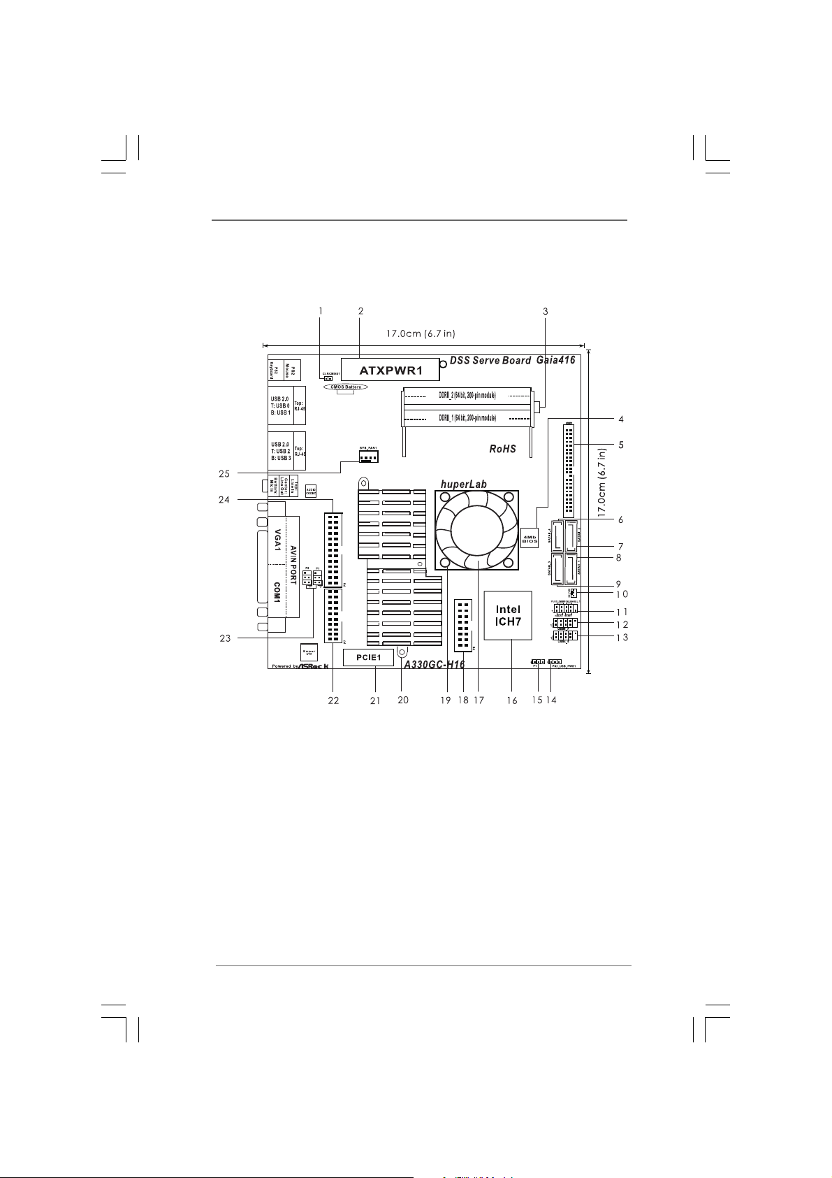
1.3 Motherboard Layout Gaia404 (A330GC-H4) /
Gaia408 (A330GC-H8) .................................................. 9
1.4 Motherboard Layout Gaia416-60 (A330GC-H16-60)
/ Gaia416-120 (A330GC-H16-120) ............................... 10
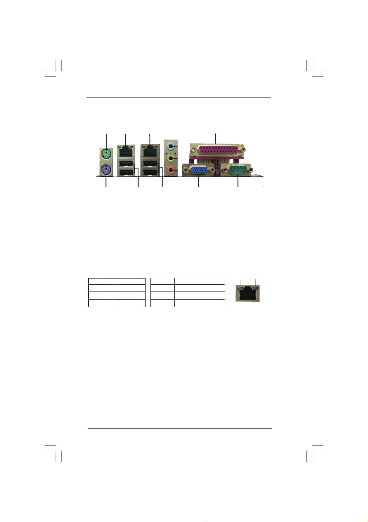
1.5 I/O Panel ........................................................................ 11
2 Installation2 Installation
2 Installation
2 Installation2 Installation
2.1 Screw Holes .................................................................. 12
2.2 Pre-installation Precautions .......................................... 12
2.3 Installation of Memory Modules (SODIMM) .................. 13
2.4 Expansion Slot (PCIE Slot) .................................................... 14
2.5 Jumpers Setup .............................................................. 14
2.6 Onboard Headers and Connectors ............................... 15
2.7 SATAII Hard Disk Setup Guide ...................................... 17
2.8 Serial ATA (SATA) / Serial ATAII (SATAII) Hard Disks
Installation ..................................................................... 18
2.9 Driver Installation Guide ............................................ 18
3 BIOS S3 BIOS S
3 BIOS S
3 BIOS S3 BIOS S
3.1 Introduction .................................................................... 19
3.1.1 BIOS Menu Bar .................................................... 19
3.1.2 Navigation Keys ................................................... 20
3.2 Main Screen .................................................................. 20
3.3 Smart Screen ................................................................ 21
3.4 Advanced Screen .......................................................... 22
3.4.1 CPU Configuration ............................................... 23
3.4.2 Chipset Configuration .......................................... 24
3.4.3 ACPI Configuration .............................................. 25
3.4.4 Storage Configuration .......................................... 26
3.4.5 Super IO Configuration ........................................ 28
3.4.6 USB Configuration ............................................... 28
3.5 Hardware Health Event Monitoring Screen ................... 29
3.6 Boot Screen ................................................................... 30
3.6.1 Boot Settings Configuration .................................. 30
3.7 Security Screen ............................................................. 31
3.8 Exit Screen .................................................................... 31
............................................................................................................
......................................................
............................................................................................................
................................................................................................................
........................................................
................................................................................................................
ETUP UTILITYETUP UTILITY
ETUP UTILITY
ETUP UTILITYETUP UTILITY
............................................................................................
..............................................
............................................................................................
5 5
5
5 5
12 12
12
12 12
19 19
19
19 19
33
3
33
Page 4

4 Sof4 Sof
tware Supportware Suppor
4 Sof
tware Suppor
4 Sof4 Sof
tware Supportware Suppor
4.1 Install Operating System ............................................... 33
4.2 Support CD Information................................................. 33
4.2.1 Running Support CD ............................................ 33
4.2.2 Drivers Menu ........................................................ 33
4.2.3 Utilities Menu ....................................................... 33
4.2.4 Contact Information ............................................. 33
5 huperVision Sof5 huperVision Sof
5 huperVision Sof
5 huperVision Sof5 huperVision Sof
5.1 Easy Steps to install software ....................................... 35
5.2 Start Recording Instruction ............................................ 37
5.3 Playback Recordings Instruction................................... 40
tt
............................................................................................
t
..............................................
tt
............................................................................................
tware Installationtware Installation
tware Installation
tware Installationtware Installation
..........................................
.....................
..........................................
33 33
33
33 33
34 34
34
34 34
44
4
44
Page 5

Chapter 1 IntroductionChapter 1 Introduction
Chapter 1 Introduction
Chapter 1 IntroductionChapter 1 Introduction
Thank you for purchasing huperLab Gaia404 / Gaia408 / Gaia416-60 / Gaia416-120
motherboard, a reliable motherboard produced under huperLab’s consistently strin-
gent quality control. It delivers excellent performance with robust design conforming
to huperLab’s commitment to quality and endurance.
In this manual, chapter 1 and 2 contain introduction of the motherboard and step-by-
step guide to the hardware installation. Chapter 3 and 4 contain the configuration
guide to BIOS setup and information of the Support CD. Chapter 5 contains installa-
tion instruction for huperLab software.
Because the motherboard specifications and the BIOS software might be
updated, the content of this manual will be subject to change without prior
notice. In case any modifications of this manual occur, the updated version
will be available on huperLab website.
huperLab website
If you require technical support related to this motherboard, please visit the
website for specific information about the model you are using.
http://www.huperlab.com/bboard/
1.1 P1.1 P
ackack
1.1 P
1.1 P1.1 P
huperLab Gaia404 / Gaia408 / Gaia416-60 / Gaia 416-120 Motherboard (Mini-ITX
Form Factor: 6.7-in x 6.7-in, 17.0 cm x 17.0 cm)
huperLab Gaia404 / Gaia408 / Gaia416-60 / Gaia 416-120 User Guide
huperLab Gaia404 / Gaia408 / Gaia416-60 / Gaia 416-120 Driver & Utility Support CD
huperVision 4000 Software CD
age Contentsage Contents
ack
age Contents
ackack
age Contentsage Contents
http://www.huperlab.com
Motherboard Accessories
Gaia404: One 4CH Video in & Audio in Cable
Gaia408: One 8CH Video in & Audio in Cable
Gaia416-60 / Gaia 416-120: One 16CH Video in Cable
I/O shield
Audio in Cable with bracket (Optional)
Two Serial ATA (SATA) Data Cable(Optional)
55
5
55
Page 6
1.21.2
SpecificationsSpecifications
1.2
Specifications
1.21.2
SpecificationsSpecifications
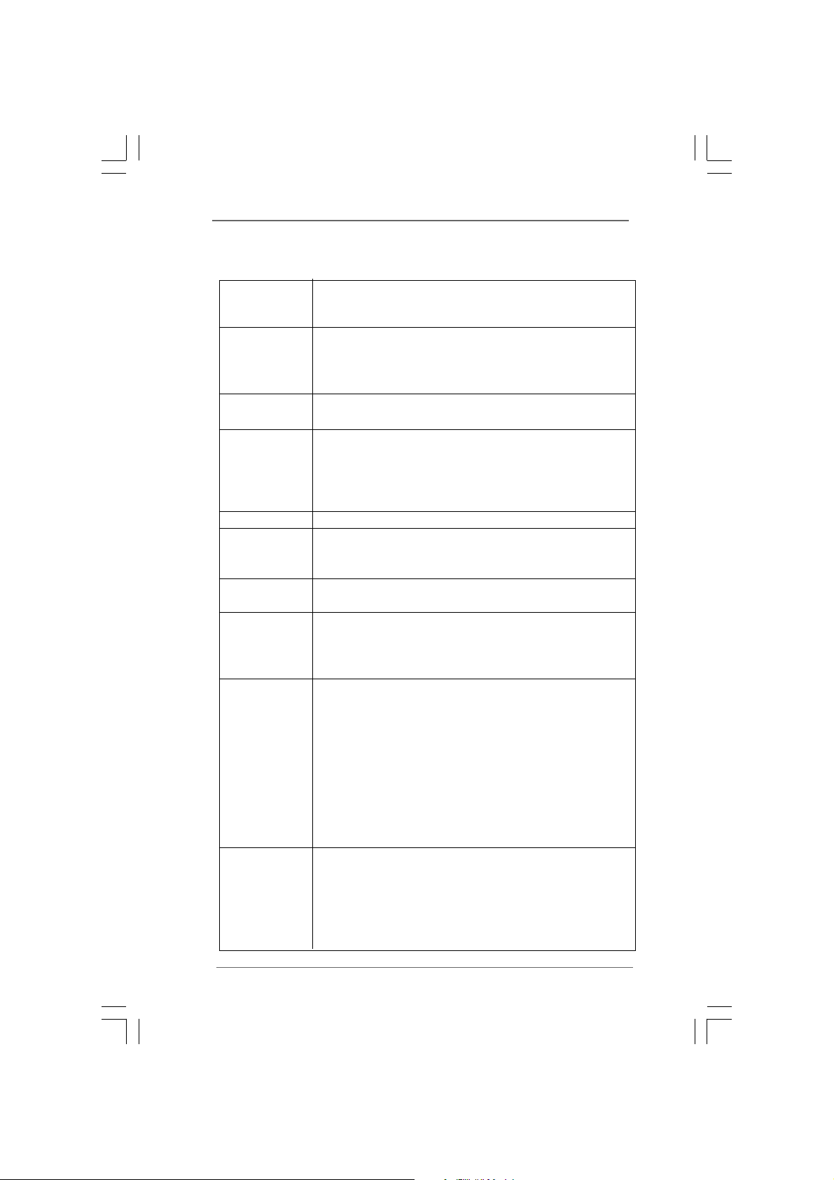
Platform - Mini-ITX Form Factor: 6.7-in x 6.7-in, 17.0 cm x 17.0 cm
- Solid Capacitor design (100% Japan-made
high-quality Conductive Polymer Capacitors)
CPU - Intel® Dual-Core AtomTM Processor 330
- Supports FSB533 MHz
- Supports Hyper-Threading Technology (see CAUTION 1)
- Supports EM64T CPU
Chipset - Northbridge: Intel® 945GC
- Southbridge: Intel® ICH7
Memory - Dual Channel DDR2 Memory Technology (see CAUTION 2)
- 2 x DDR2 SODIMM slots
- Supports DDR2 533 / 667/ 800 SODIMM, run at 533 speed,
non-ECC, un-buffered memory
- Max. capacity of system memory: 4GB (see CAUTION 3)
Expansion Slot - 1 x PCI Express slot
Graphics - Intel® Graphics Media Accelerator 950
- Pixel Shader 2.0, DirectX 9.0
- Max. shared memory 224MB (see CAUTION 4)
Audio - 5.1 CH Windows® VistaTM Premium Level HD Audio
(Realtek ALC662 Audio Codec)
LAN - 2 x PCIE Gigabit LAN 10 / 100 / 1000 Mb/s
- Realtek RTL8111DL
- Supports Wake-On-LAN
- Supports Dual LAN features
Rear Panel I/O I/O Panel
- 1 x PS/2 Mouse Port
- 1 x PS/2 Keyboard Port
- 1 x DVR Audio / Video input
- 1 x Serial Port: COM1
- 1 x VGA Port
- 4 x Ready-to-Use USB 2.0 Ports
- 2 x RJ-45 LAN Ports with LED (ACT/LINK LED and SPEED
LED)
- HD Audio Jack: Line in / Front Speaker / Microphone
Connector - 4 x SATAII 3.0 Gb/s connectors (No Support for RAID and
“Hot Plug” functions) (see CAUTION 5)
- 1 x ATA100 mini IDE connector with 5V power (supports 2 x
IDE devices)
- System / NB FAN connector
- 24 pin ATX power connector
66
6
66
Page 7
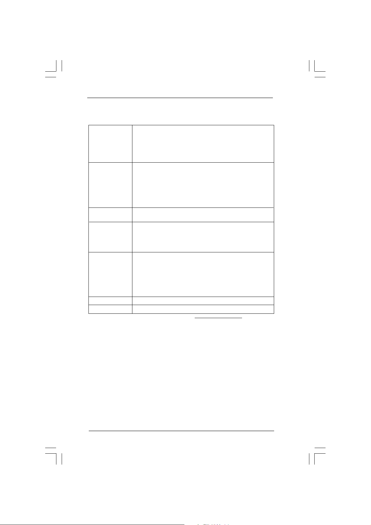
- 2 x USB 2.0 headers (support 4 USB 2.0 ports) (see CAU-
TION 6)
- 16 pin GPIO connector (support 8 GPIO)
- 20 pin Audio input connector (support 16CH Audio in)
- 26 pin Video input connector
BIOS Feature - 4Mb AMI BIOS
- AMI Legal BIOS
- Supports “Plug and Play”
- ACPI 1.1 Compliance Wake Up Events
- AMBIOS 2.3.1 Support
- Supports Smart BIOS
Support CD - Drivers, Utilities, Antivirus Software (Trial Version), huperVision
4000 Surveillance Software Suite
Unique Feature - ASRock Instant Flash (see CAUTION 7)
- Hybrid Booster:
- ASRock U-COP
- Boot Failure Guard (B.F.G.)
Hardware - System Temperature Sensing
Monitor - CPU Temperature Sensing
- NB Fan Tachometer
- System Fan Tachometer
- System Quiet Fan
- Voltage Monitoring: +12V, +5V, +3.3V, Vcore
OS - Microsoft® Windows® XP / Vista
TM
Certifications - FCC, CE
* For detailed product information, please visit website:
http://www.huperlab.com
77
7
77
Page 8

CAUTION!
1. About the setting of “Hyper Threading Technology”, please refer to section
3.4.1(page 23)
2. This motherboard supports Dual Channel Memory Technology. Before you
implement Dual Channel Memory Technology, make sure to read the instal-
lation guide of memory modules in section 2.3 (page 13) for proper installation.
3. Due to chipset and CPU limitation, the actual memory size might be less
4GB for the reservation of system usage under Windows® XP, Win-
than
dows® VistaTM.
4. The maximum shared memory size is defined by the chipset vendor and is
subject to change. Please check Intel® website for the latest information.
5. Before installing SATAII hard disk to SATAII connector, please read “SATAII
Hard Disk Setup Guide” in section 2.8 (page 18) to adjust your SATAII hard disk
drive to SATAII mode. You can also connect SATA hard disk to SATAII connec-
tor directly.
6. Power Management for USB 2.0 works fine under Microsoft® Windows
VistaTM / XP SP1 or SP2.
7. ASRock Instant Flash is a BIOS flash utility embedded in Flash ROM. This
convenient BIOS update tool allows you to update system BIOS without
entering operating systems first like MS-DOS or Windows®. With this utility,
you can press <F6> key during the POST or press <F2> key to BIOS setup
menu to access ASRock Instant Flash. Just launch this tool and save the
new BIOS file to your USB flash drive, floppy disk or hard drive, then you can
update your BIOS only in a few clicks without preparing an additional floppy
diskette or other complicated flash utility. Please be noted that the USB
flash drive or hard drive must use FAT32/16/12 file system.
®
88
8
88
Page 9
1.3 Motherboard L1.3 Motherboard L
1.3 Motherboard L
1.3 Motherboard L1.3 Motherboard L
(A330GC (A330GC
(A330GC
(A330GC (A330GC
-H8)-H8)
-H8)
-H8)-H8)
ayout Gaia404 (A330GCayout Gaia404 (A330GC
ayout Gaia404 (A330GC
ayout Gaia404 (A330GCayout Gaia404 (A330GC
-H4) / Gaia408-H4) / Gaia408
-H4) / Gaia408
-H4) / Gaia408-H4) / Gaia408
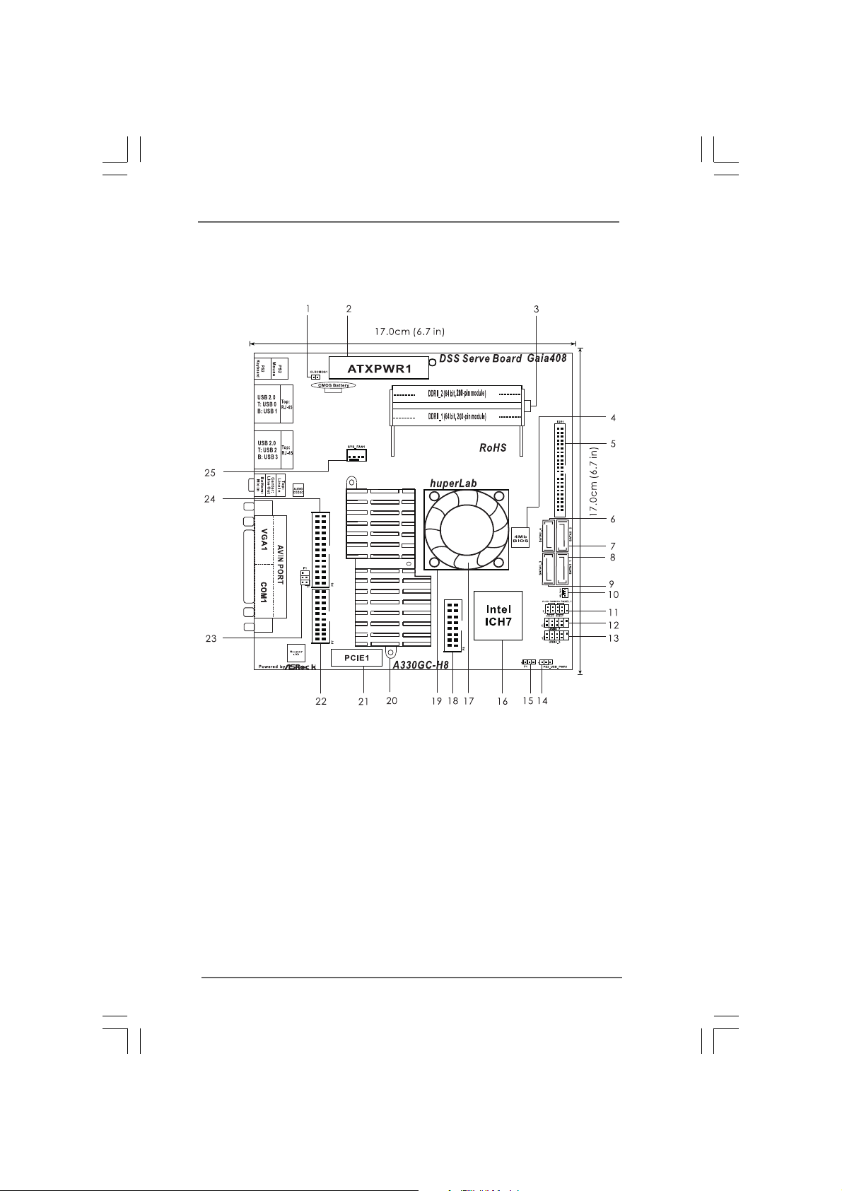
1 Clear CMOS Jumper (CLRCMOS1) 13 USB 2.0 Header (USB 4_5, Blue)
2 ATX Power Connector (ATXPWR1) 14 PS2_USB_PWR1 Jumper
3 2 x 200-pin DDR2 SODIMM Slots 15 Watchdog Function Jumper
(Dual Channel: DDRII_1, DDRII_2; White) 16 South Bridge Controller
4 BIOS SPI Chip 17 NB Fan
5 IDE1 Connector (IDE1) 18 GPIO
6 SATAII Connector (SATAII_4; Orange) 19 North Bridge Controller
7 SATAII Connector (SATAII_2; Red) 20 CPU Heat Sink
8 SATAII Connector (SATAII_1; Red) 21 PCIE Slot (PCIE1)
9 SATAII Connector (SATAII_3; Orange) 22 Audio In
10 NB Fan Connector (NB_Fan1) 23 Composite Out
11 System Panel Header (PANEL1;Orange) 24 Video In
12 USB 2.0 Header (USB 6_7, Blue) 25 System Fan Connector (SYS_FAN1)
99
9
99
Page 10
1.4 Motherboard L1.4 Motherboard L
1.4 Motherboard L
1.4 Motherboard L1.4 Motherboard L
/ Gaia416-120 (A330GC / Gaia416-120 (A330GC
/ Gaia416-120 (A330GC
/ Gaia416-120 (A330GC / Gaia416-120 (A330GC
ayout Gaia416-60 (A330GCayout Gaia416-60 (A330GC
ayout Gaia416-60 (A330GC
ayout Gaia416-60 (A330GCayout Gaia416-60 (A330GC
-H16-120)-H16-120)
-H16-120)
-H16-120)-H16-120)
-H16-60)-H16-60)
-H16-60)
-H16-60)-H16-60)
1 Clear CMOS Jumper (CLRCMOS1) 13 USB 2.0 Header (USB 4_5, Blue)
2 ATX Power Connector (ATXPWR1) 14 PS2_USB_PWR1 Jumper
3 2 x 200-pin DDR2 SODIMM Slots 15 Watchdog Function Jumper
(Dual Channel: DDRII_1, DDRII_2; White) 16 South Bridge Controller
4 BIOS SPI Chip 17 NB Fan
5 IDE1 Connector (IDE1) 18 GPIO
6 SATAII Connector (SATAII_4; Orange) 19 North Bridge Controller
7 SATAII Connector (SATAII_2; Red) 20 CPU Heat Sink
8 SATAII Connector (SATAII_1; Red) 21 PCIE Slot (PCIE1)
9 SATAII Connector (SATAII_3; Orange) 22 Audio In
10 NB Fan Connector (NB_Fan1) 23 Composite Out
11 System Panel Header (PANEL1;Orange) 24 Video In
12 USB 2.0 Header (USB 6_7, Blue) 25 System Fan Connector (SYS_FAN1)
1010
10
1010
Page 11
1.5 I/O P1.5 I/O P
1
2
3
4
5
6
7
8
9
1 0
1 1
1 2
1.5 I/O P
1.5 I/O P1.5 I/O P
*2 LAN RJ-45 Port (LAN1) 8 COM Port
*3 LAN RJ-45 Port (LAN2) 9 VGA Port
5 Front Speaker (Lime) 11 USB 2.0 Ports (USB01)
* There are two LED next to the LAN port. Please refer to the table below for the LAN port LED
indications.
Activity / Link LED SPEED LED
Status Description Status Description
Off No Link Off 10Mbps connection
Blinking Data Activity Orange 100Mbps connection
On Link Green 1Gbps connection
anelanel
anel
anelanel
1 PS/2 Mouse Port (Green) 7 AV IN Port
4 Line In (Light Blue) 10 USB 2.0 Ports (USB23)
6 Microphone (Pink) 12 PS/2 Keyboard Port (Purple)
LAN Port LED Indications
ACT/LINK
LED
LAN Port
SPEED
LED
1111
11
1111
Page 12
Chapter 2 InstallationChapter 2 Installation
Chapter 2 Installation
Chapter 2 InstallationChapter 2 Installation
Gaia404 / Gaia408 / Gaia416-60 / Gaia416-120 are a Mini-IXT form factor (6.7" x
6.7", 17.0 x 17.0 cm) motherboard. Before you install the motherboard, study the
configuration of your chassis to ensure that the motherboard fits into it.
Before installation or removal of the motherboard, please ensure to unplug
thepower cord. Failure to do so may cause physical injuries and
damages to motherboard components.
2.1 Screw Holes2.1 Screw Holes
2.1 Screw Holes
2.1 Screw Holes2.1 Screw Holes
Place screws into the holes indicated by circles to secure the motherboard to the
chassis.
Do not over-tighten the screws! Doing so may damage the motherboard.
2.2 P2.2 P
re-installation Pre-installation P
2.2 P
re-installation P
2.2 P2.2 P
re-installation Pre-installation P
Take note of the following precautions before you install motherboard components or
change any motherboard settings.
1. Unplug the power cord from the wall socket before touching any component.
2. To avoid damaging the motherboard components due to static electricity, NEVER
place your motherboard directly on the carpet or the like. Also remember to use
a grounded wrist strap or touch a safety grounded object before you handle
components.
3. Hold components by the edges and do not touch the ICs.
4. Whenever you uninstall any component, place it on a grounded antistatic pad or
in the bag that comes with the component.
recautionsrecautions
recautions
recautionsrecautions
1212
12
1212
Before you install or remove any component, ensure that the power is
switched off or the power cord is detached from the power supply.
Failure to do so may cause severe damage to the motherboard, peripherals,
and/or components.
Page 13
2.3 Installation of Memor2.3 Installation of Memor
not ch
not ch
2.3 Installation of Memor
2.3 Installation of Memor2.3 Installation of Memor
Gaia404 / Gaia408 / Gaia416-60 / Gaia416-120 motherboard provides two 200-pin
DDR2 (Double Data Rate 2) SODIMM slots, and supports Dual Channel Memory
Technology. For dual channel configuration, you always need to install two
identical (the same brand, speed, size and chip-type) memory modules in the
DDR2 SODIMM slots to activate Dual Channel Memory Technology. Otherwise, it
will operate at single channel mode.
1. It is not allowed to install a DDR memory module into DDR2 slot;
otherwise, this motherboard and SODIMM may be damaged.
2. If you install only one memory module or two non-identical memory
modules, it is unable to activate the Dual Channel Memory Technology.
Installing a SODIMMInstalling a SODIMM
Installing a SODIMM
Installing a SODIMMInstalling a SODIMM
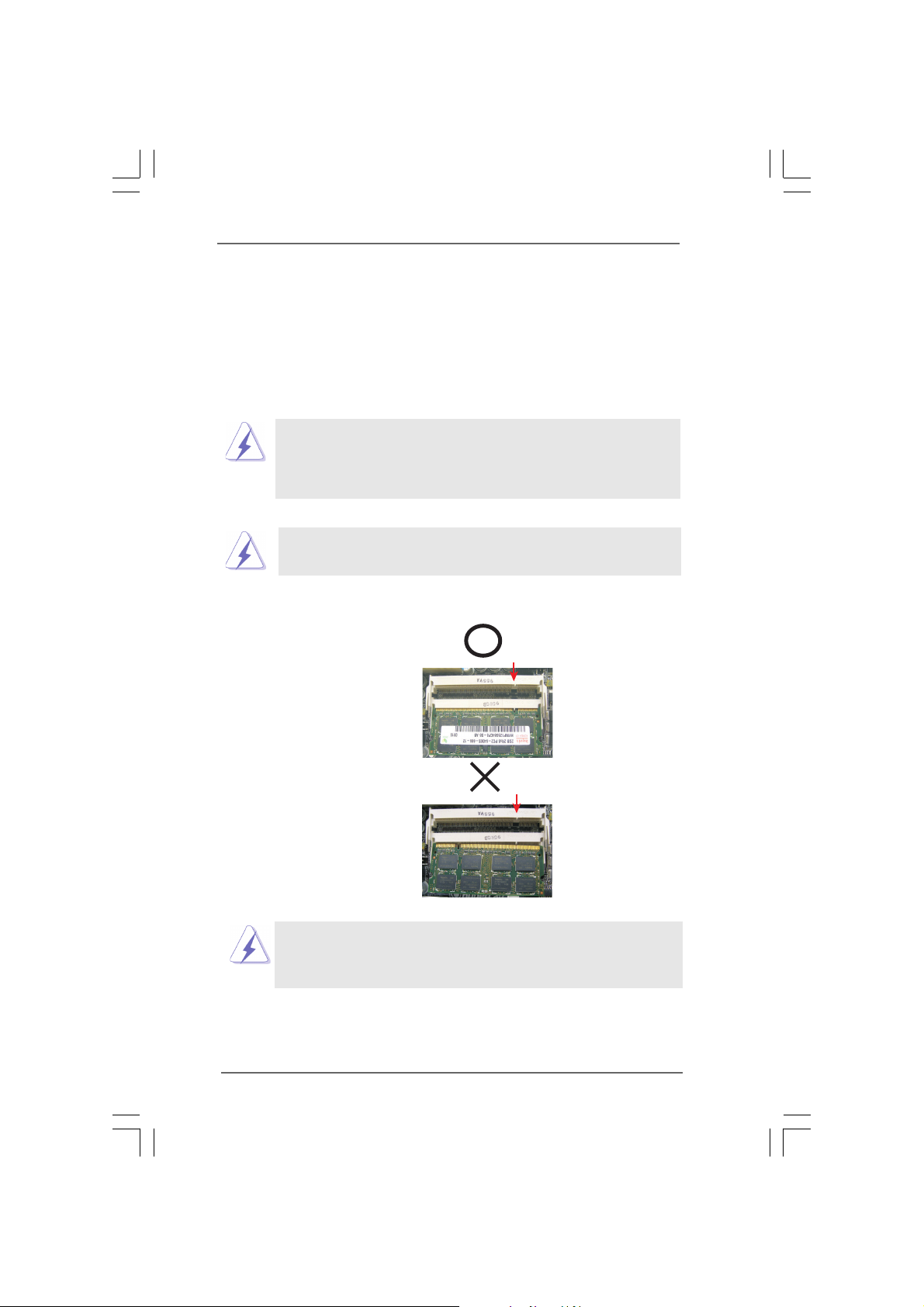
Please make sure to disconnect power supply before adding or removing
SODIMM or the system components.
Step 1. Unlock a SODIMM slot by pressing the retaining clips outward.
Step 2. Align a SODIMM on the slot such that the notch on the SODIMM matches
the break on the slot.
y Modules (SODIMM)y Modules (SODIMM)
y Modules (SODIMM)
y Modules (SODIMM)y Modules (SODIMM)
The SODIMM only fits in one correct direction. It will cause permanent dam-
age to the motherboard and the SODIMM if you force the SODIMM into the
slot at incorrect direction.
Step 3. Firmly insert the SODIMM into the slot until the retaining clips at both ends
fully snap back in place and the SODIMM is properly seated.
1313
13
1313
Page 14
2.4 Expansion Slot (PCIE Slot)2.4 Expansion Slot (PCIE Slot)
+5VSB
2_3
+5V
1_2
2.4 Expansion Slot (PCIE Slot)
2.4 Expansion Slot (PCIE Slot)2.4 Expansion Slot (PCIE Slot)
There is One PCIE slot on this motherboard.
PCIE slot: PCIE slot is used for PCI Express cards with x 1 lane width cards, such as
Gigabit LAN card, SATA2 card, etc.
Installing an expansion cardInstalling an expansion card
Installing an expansion card
Installing an expansion cardInstalling an expansion card
Step 1. Before installing the expansion card, please make sure the power supply is
switched off or the power cord is unplugged. Please read the documenta-
tion of the expansion card and make adjustments to hardware settings for
the card before you start the installation.
Step 2. Remove the bracket facing the slot that you intend to use. Keep the screws
for later use.
Step 3. Align the card connector with the slot and press firmly until the card is com-
pletely seated on the slot.
Step 4. Fasten the card to the chassis with screws.
2.5 Jumpers Setup 2.5 Jumpers Setup
2.5 Jumpers Setup
2.5 Jumpers Setup 2.5 Jumpers Setup
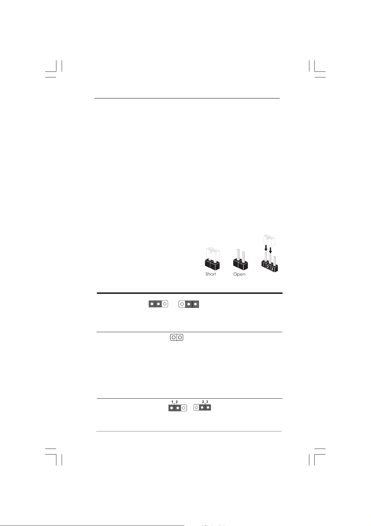
The illustrations show how jumpers are
setup. When the jumper cap is placed on
pins, the jumper is “Short”. When no jumper
cap is placed on pins, the jumper is “Open”.
The illustrations show a 3-pin jumper, whose
pin1 and pin2 are “Short” when jumper cap is
placed on top.
Jumper Setting Description
PS2_USB_PWR1 Short pin2, pin3 to enable
(see p.9/10 No. 14) +5VSB (standby) for PS/2
or USB wake up events.
Note: To select +5VSB, it requires 2 Amp and higher standby current provided by
power supply.
Clear CMOS
(CLRCMOS1, 2-pin jumper)
(see p.9/10 No. 1)
Note: CLRCMOS1 allows you to clear the data in CMOS. The data in CMOS includes
system setup information such as system password, date, time, and system
setup parameters. To clear and reset the system parameters to default setup,
please turn off the computer and unplug the power cord from the power supply.
After waiting for 15 seconds, use a jumper cap to short 2 pins on CLRCMOS1
for 5 seconds.
Watchdog Function Jumpter Short pin1-2 to enable
(see p.9/10 No. 15) watchdog, short pin 2-3 to
2-pin jumper
disable watchdog.
1414
14
1414
Page 15
USB _PWR
USB _PWR
P+7
P-7
P+6
P-6
GND
GND
DUM MY
1
USB _PWR
USB _PWR
P+5
P-5
P+4
P-4
GND
GND
DUM MY
1
2.6 Onboard Headers and Connectors2.6 Onboard Headers and Connectors
IDE1
PIN1
GND
PWR BTN#
PLE D-
PLE D+
DUM MY
RES ET#
GND
HDL ED+
HDL ED-
1
2.6 Onboard Headers and Connectors
2.6 Onboard Headers and Connectors2.6 Onboard Headers and Connectors
Onboard headers and connectors are NOT jumpers. Do NOT place jumper
caps over these headers and connectors. Placing jumper caps over the
headers and connectors will cause permanent damage of the
motherboard!
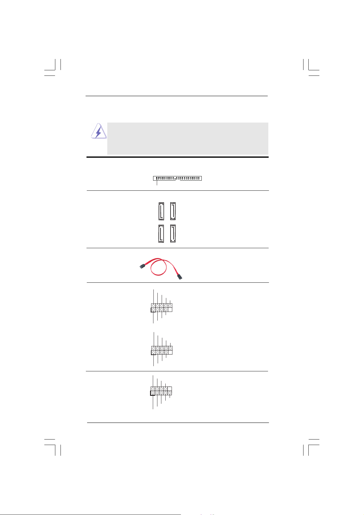
Primary IDE Connector
(43-pin IDE1, see p.10/11 No. 5)
Serial ATAII Connectors These Serial ATAII (SATEII)
(SATAII_1: see p.9/10, No. 8) connectors support SATAII
(SATAII_2: see p.9/10, No. 7) or SATA hard disk for internal
SATAII_4
SATAII_2
(SATAII_3: see p.9/10, No. 9) storage devices. The current
(SATAII_4: see p.9/10, No. 6) SATAII interface allows up to
SATAII_3
SATAII_1
3.0 Gb/s data transfer rate.
Serial ATA (SATA) Either end of the SATA data cable
Data Cable can be connected to the SATA /
(Optional) SATAII hard disk or the SATAII
USB 2.0 Headers Besides two default USB 2.0
(9-pin USB6_7) ports on the I/O panel, there are
(see p.9/10 No. 12) two USB 2.0 headers on this
connector on the motherboard.
motherboard. Each USB 2.0
header can support two USB
2.0 ports.
(9-pin USB4_5)
(see p.9/10 No. 13)
System Panel Header This header accommodates
(9-pin PANEL1) several system front panel
(see p.9/10 No. 11) functions.
1515
15
1515
Page 16
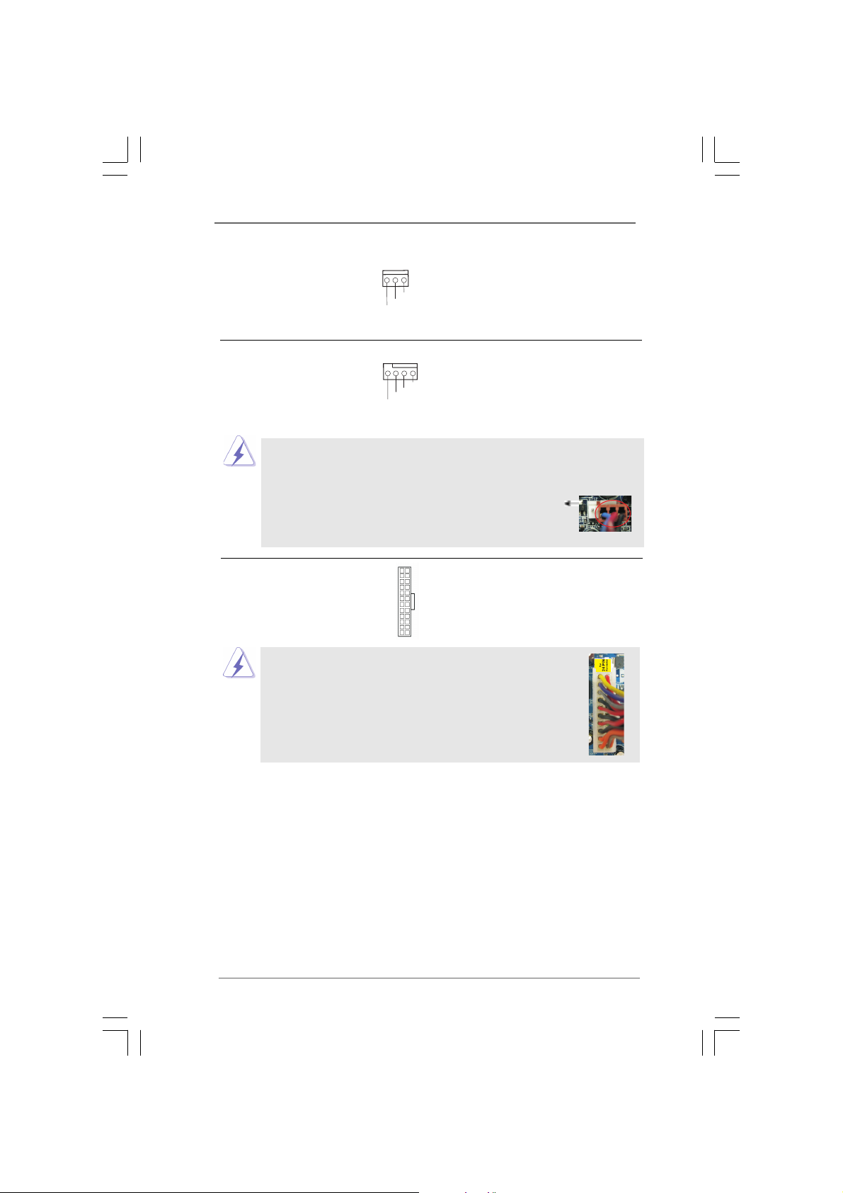
NB Fan Connector Please connect a NB fan
GND
+12 V
CHA _FAN_S PEED
GND
+12 V
CPU _FAN_S PEED
FAN_ SPEED _CONT ROL
(3-pin NB_FAN1) cable to this connector and
(see p.9/10 No. 10) match the black wire to the
ground pin.
System Fan Connector Please connect a System fan
(4-pin SYS_FAN1) cable to this connector and
4 3 2 1
(see p.9/10 No. 25) match the black wire to the
ground pin.
Though this motherboard provides 4-Pin System fan (Quiet Fan) support, the 3-Pin
System fan still can work successfully even without the fan speed control function.
If you plan to connect the 3-Pin fan to the System fan connector on this
motherboard, please connect it to Pin 1-3.
24
ATX Power Connector Please connect an ATX power
(24-pin ATXPWR1) supply to this connector.
(see p.9/10 No. 2)
12
13
1
Though this motherboard provides 24-pin ATX power connector,
it can still work if you adopt a traditional 20-pin ATX power supply.
To use the 20-pin ATX power supply, please plug your power
supply along with Pin 1 and Pin 13.
20-Pin ATX Power Supply Installation
Pin 1-3 Connected
3-Pin Fan Installation
12
1
24
13
1616
16
1616
Page 17
2.72.7
1357
2468
1357
2468
SASA
TT
2.7
2.72.7
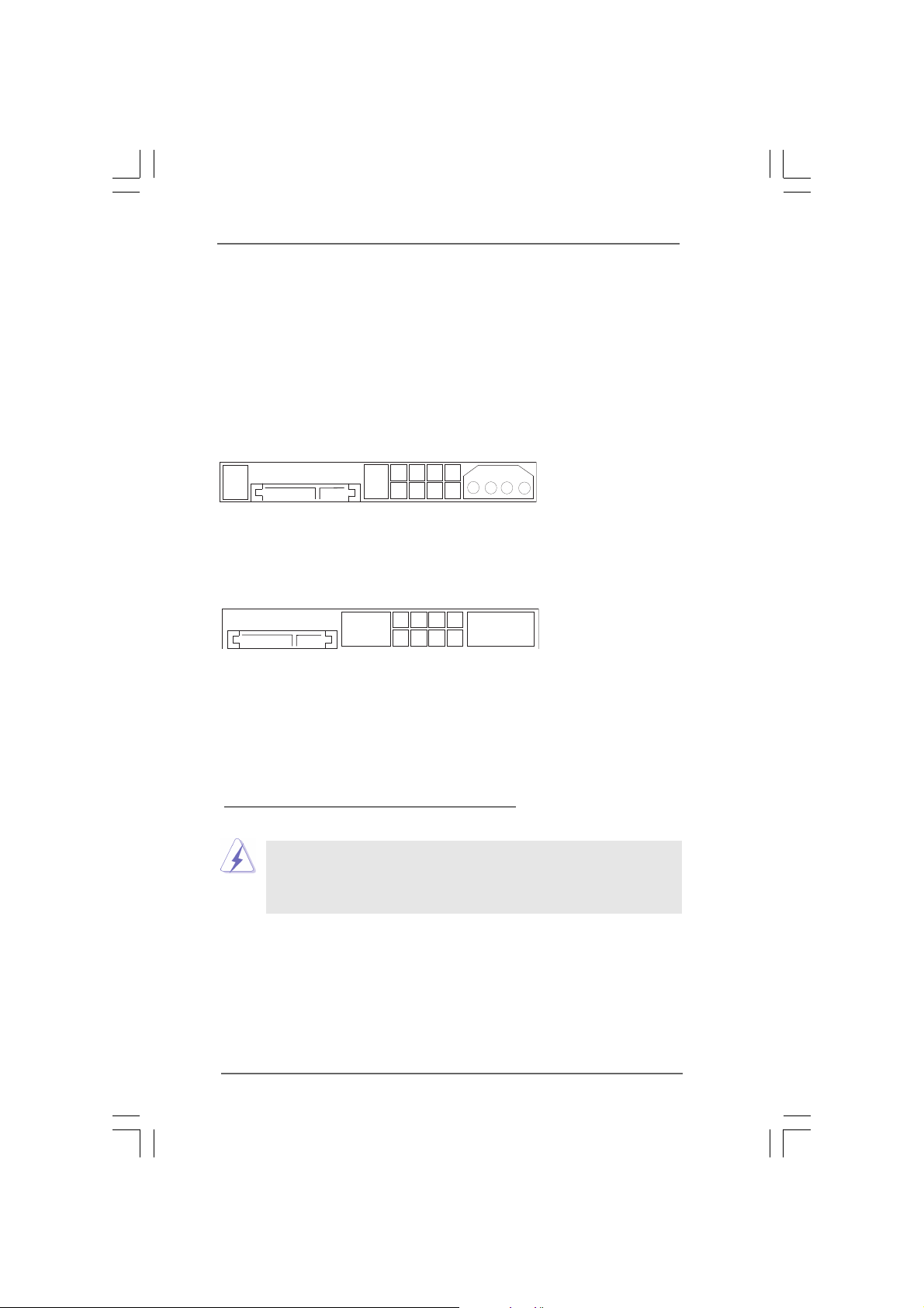
Before installing SATAII hard disk to your computer, please carefully read SATAII
hard disk setup guide below. Some default setting of SATAII hard disks may not be
at SATAII mode, which operates with the best performance. In order to enable
SATAII function, please follow the instruction with different vendors to correctly
adjust your SATAII hard disk to SATAII mode in advance; otherwise, your SATAII
hard disk may fail to run at SATAII mode.
Western Digital
If pin 5 and pin 6 are shorted, SATA 1.5Gb/s will be enabled.
On the other hand, if you want to enable SATAII 3.0Gb/s, please remove the
jumpers from pin 5 and pin 6.
SAMSUNG
If pin 3 and pin 4 are shorted, SATA 1.5Gb/s will be enabled.
On the other hand, if you want to enable SATAII 3.0Gb/s, please remove the
jumpers from pin 3 and pin 4.
AII Hard Disk Setup GuideAII Hard Disk Setup Guide
SA
T
AII Hard Disk Setup Guide
SASA
TT
AII Hard Disk Setup GuideAII Hard Disk Setup Guide
HITACHI
Please use the Feature Tool, a DOS-bootable tool, for changing various ATA
features. Please visit HITACHI’s website for details:
http://www.hitachigst.com/hdd/support/download.htm
The above examples are just for your reference. For different SATAII hard
disk products of different vendors, the jumper pin setting methods may not
be the same. Please visit the vendors’ website for the updates.
1717
17
1717
Page 18

2.82.8
Serial ASerial A
2.8
Serial A
2.82.8
Serial ASerial A
Installation Installation
Installation
Installation Installation
This motherboard adopts Intel® ICH7 south bridge chipset that supports Serial ATA
(SATA) / Serial ATAII (SATAII) hard disks. You may install SATA / SATAII hard disks
on this motherboard for internal storage devices. This section will guide you to
install the SATA / SATAII hard disks.
STEP 1: Install the SATA / SATAII hard disks into the drive bays of your chassis.
STEP 2: Connect the SATA power cable to the SATA / SATAII hard disk.
STEP 3: Connect one end of the SATA data cable to the motherboard’s SATAII
STEP 4: Connect the other end of the SATA data cable to the SATA / SATAII hard
2.92.9
Driver Installation GuideDriver Installation Guide
2.9
Driver Installation Guide
2.92.9
Driver Installation GuideDriver Installation Guide
To install the drivers to your system, please insert the support CD to your optical
drive first. Then, the drivers compatible to your system can be auto-detected and
listed on the support CD driver page. Please follow the order accordingly to install
those required drivers.
TT
T
TT
connector.
disk.
A (SAA (SA
A (SA
A (SAA (SA
TT
A) / Serial AA) / Serial A
T
A) / Serial A
TT
A) / Serial AA) / Serial A
TT
AII (SAAII (SA
T
AII (SA
TT
AII (SAAII (SA
TT
AII) Hard DisksAII) Hard Disks
T
AII) Hard Disks
TT
AII) Hard DisksAII) Hard Disks
1818
18
1818
Page 19

Chapter 3 BIOS SETUP UTILITYChapter 3 BIOS SETUP UTILITY
Chapter 3 BIOS SETUP UTILITY
Chapter 3 BIOS SETUP UTILITYChapter 3 BIOS SETUP UTILITY
3.13.1
IntroductionIntroduction
3.1
Introduction
3.13.1
IntroductionIntroduction
This section explains how to use the BIOS SETUP UTILITY to configure your system.
The BIOS FWH chip on the motherboard stores the BIOS SETUP UTILITY. You may
run the BIOS SETUP UTILITY when you start up the computer. Please press <F2>
during the Power-On-Self-Test (POST) to enter the BIOS SETUP UTILITY, otherwise,
POST will continue with its test routines.
If you wish to enter the BIOS SETUP UTILITY after POST, restart the system by
pressing <Ctl> + <Alt> + <Delete>, or by pressing the reset button on the system
chassis. You may also restart by turning the system off and then back on.
Because the BIOS software is constantly being updated, the fol-
lowing BIOS setup screens and descriptions are for reference
purpose only, and they may not exactly match what you see on
your screen.
3.1.13.1.1
BIOS Menu BarBIOS Menu Bar
3.1.1
BIOS Menu Bar
3.1.13.1.1
BIOS Menu BarBIOS Menu Bar
The top of the screen has a menu bar with the following selections:
Main To set up the system time/date information
Smart To load the BIOS according to your requirements
Advanced To set up the advanced BIOS features
H/W Monitor To monitor and set up the hardware features
Boot To set up the default system device to locate and load the
operating System
Security To set up the security features
Exit To exit the current screen or the BIOS SETUP UTILITY
Use < > key or < > key to choose among the selections on the menu
bar, and then press <Enter> to get into the sub screen.
1919
19
1919
Page 20
3.1.23.1.2
BIO S SETUP UTIL ITY
Mai n
Sma rt H/W Mon itor Bo ot Secu rity Ex itAdv anced
Sys tem Ove rview
Sys tem Time
Sys tem Dat e
[ :00 :09]
[Mo n 08/03 /2009 ]
Use [ Enter ], [TAB]
or [S HIFT-TAB] t o
sel ect a fie ld.
Use [ +] or [-] t o
con figure s ystem T ime.
Sel ect Scre en
Sel ect Ite m
+- Ch ange Fi eld
Tab Sel ect Fie ld
F1 Ge neral H elp
F9 Lo ad Defa ults
F10 S ave and E xit
ESC E xit
v02 .54 (C) C opyri ght 198 5-200 5, A meric an Mega trend s, Inc.
14
BIO S Ve rsion
Proc essor Ty pe
Proc essor S peed
Mic rocode U pdate
Total M emory
Cac he Size
DDR II1
DDR II2
: Gai a408 P1 .00
: Int el (R) Ato m (TM) CP U 330 @
1.6 0GHz (6 4bit)
: 160 0MHz
: 102 4KB
: 106 C2/20 D
: 204 8MB wit h 8MB sha red memo ry
Dua l-Cha nnel Me mory Mo de
: 104 8MB/2 66MHz ( DDRII 533)
: 104 8MB/2 66MHz ( DDRII 533)
3.1.2
3.1.23.1.2
Navigation KNavigation K
Navigation K
Navigation KNavigation K
eyseys
eys
eyseys
Please check the following table for the function description of each navigation
key.
Navigation Key(s) Function Description
/ Moves cursor left or right to select Screens
/ Moves cursor up or down to select items
+ / - To change option for the selected items
<Enter> To bring up the selected screen
<F1> To display the General Help Screen
<F9> To load optimal default values for all the settings
<F10> To save changes and exit the BIOS SETUP UTILITY
<ESC> To jump to the Exit Screen or exit the current screen
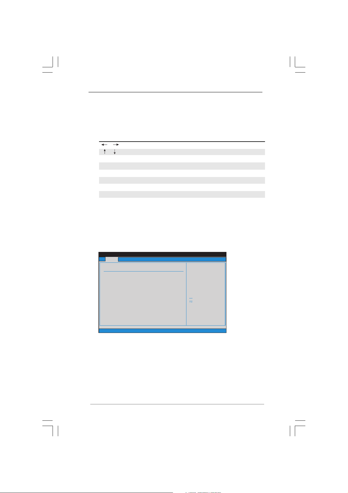
3.2 Main Screen3.2 Main Screen
3.2 Main Screen
3.2 Main Screen3.2 Main Screen
When you enter the BIOS SETUP UTILITY, the Main screen will appear and
display the system overview.
Gaia404 (A330GC-H4) / Gaia408 (A330GC-H8)
2020
20
2020
System Time [Hour:Minute:Second]
Use this item to specify the system time.
System Date [Day Month/Date/Year]
Use this item to specify the system date.
Page 21
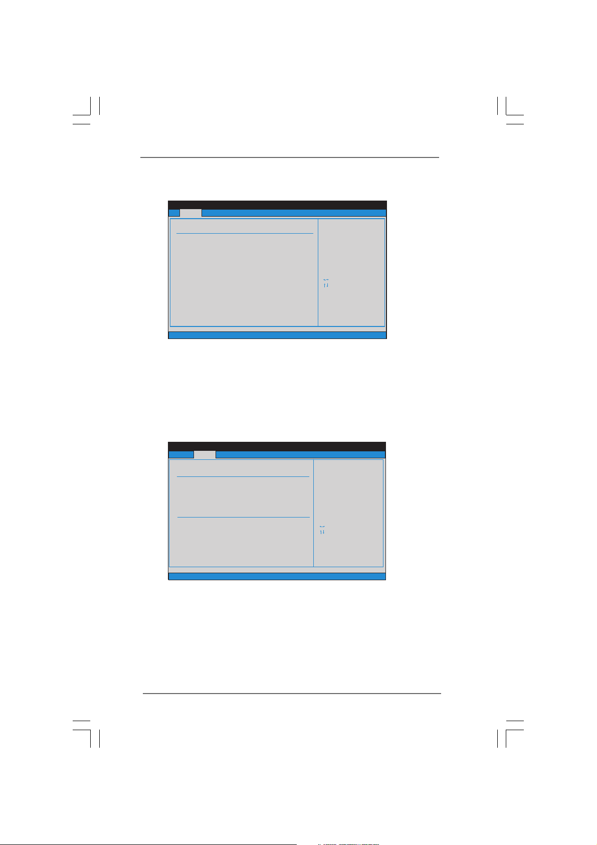
Gaia416-60 (A330GC-H16-60) / Gaia416-120 (A330GC-H16-120)
BIO S SETUP U TILIT Y
Mai n
Adv anced H /W Moni tor Bo ot Secu rity Ex it
Sma rt Sett ings
Exi t syste m setup
aft er s aving t he
cha nges.
F10 k ey can be u sed
for t his ope ratio n.
Sel ect Scre en
Sel ect Ite m
Ent er Go t o Sub Scre en
F1 Ge neral H elp
F9 Lo ad Defa ults
F10 S ave and E xit
ESC E xit
v02 .54 (C) C opyri ght 198 5-200 5, A meric an Mega trend s, Inc.
Sma rt
Sav e Chang es and Ex it
Loa d BIOS De fault s
BIO S Updat e Utili ty
ASR ock Ins tant Fl ash
BIO S SETUP U TILIT Y
Mai n
Sma rt H/W Mon itor Bo ot Secu rity Ex itAd vance d
Sys tem Ove rview
Sys tem Time
Sys tem Dat e
[ :00 :09]
[Mo n 08/03 /2009 ]
Use [ Enter ], [TAB]
or [S HIFT-TAB] t o
sel ect a fie ld.
Use [ +] or [-] t o
con figure s ystem T ime.
Sel ect Scre en
Sel ect Ite m
+- Ch ange Fi eld
Tab Sel ect Fie ld
F1 Ge neral H elp
F9 Lo ad Defa ults
F10 S ave and E xit
ESC E xit
v02 .54 (C) C opyri ght 198 5-200 5, A meric an Mega trend s, Inc.
14
BIO S Ve rsion
Proc essor Ty pe
Proc essor S peed
Mic rocode U pdate
Total M emory
Cac he Size
DDR II1
DDR II2
: Gai a416 P1 .00
: Int el (R) Ato m (TM) CP U 330 @
1.6 0GHz (6 4bit)
: 160 0MHz
: 102 4KB
: 106 C2/20 D
: 204 8MB wit h 8MB sha red memo ry
Dua l-Cha nnel Me mory Mo de
: 102 4MB/2 66MHz ( DDRII 533)
: 102 4MB/2 66MHz ( DDRII 533)
System Time [Hour:Minute:Second]
Use this item to specify the system time.
System Date [Day Month/Date/Year]
Use this item to specify the system date.
3.3 Smart Screen
In the Smart screen, you can load the BIOS setup
according to your requirements.
Save Changes and Exit
When you select this option, it will pop-out the following message, “Save
configuration changes and exit setup?” Select [OK] to save the changes
and exit the BIOS SETUP UTILITY.
Load BIOS Defaults
Load BIOS default values for all the setup questions. F9 key can be used
for this operation.
2121
21
2121
Page 22
ASRock Instant Flash
BIO S SETUP U TILIT Y
Mai n Smart
H/W M onito r Boot S ecuri ty Exit
Sel ect Scre en
Sel ect Ite m
Ent er Go to S ub Scre en
F1 Ge neral H elp
F9 Lo ad Defa ults
F10 S ave and E xit
ESC E xit
v02 .54 (C) C opyri ght 198 5-200 5, A meric an Mega trend s, Inc.
Adv anced
Adv anced S ettin gs
CPU C onfig urati on
Chi pset Co nfigu ratio n
Sto rage Co nfigu ratio n
Sup erIO Co nfigu ratio n
USB C onfig urati on
ACP I Confi gurat ion
Con figure C PU.
ASRock Instant Flash is a BIOS flash utility embedded in Flash ROM. This
convenient BIOS update tool allows you to update system BIOS without
entering operating systems first like MS-DOS or Windows®. Just launch
this tool and save the new BIOS file to your USB flash drive, floppy disk or
hard drive, then you can update your BIOS only in a few clicks without
preparing an additional floppy diskette or other complicated flash utility.
Please be noted that the USB flash drive or hard drive must use FAT32/16/
12 file system. If you execute ASRock Instant Flash utility, the utility will
show the BIOS files and their respective information. Select the proper
BIOS file to update your BIOS, and reboot your system after BIOS update
process completes.
3.43.4
Advanced ScreenAdvanced Screen
3.4
Advanced Screen
3.43.4
Advanced ScreenAdvanced Screen
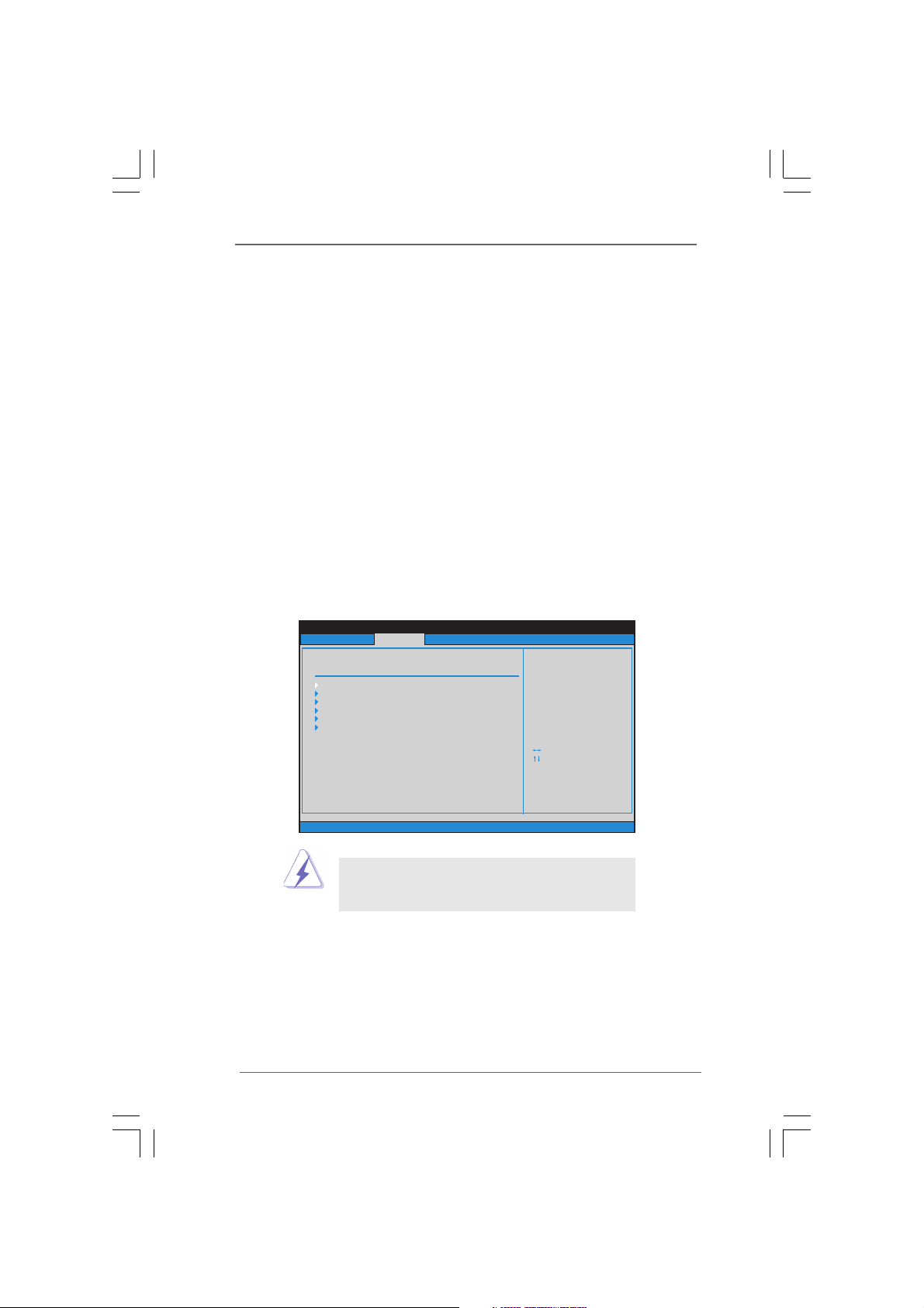
In this section, you may set the configurations for the following items: CPU
Configuration, Chipset Configuration, ACPI Configuration, Storage Configuration, Super
IO Configuration, and USB Configuration.
2222
22
2222
Setting wrong values in this section may cause
the system to malfunction.
Page 23

3.4.1 3.4.1
BIO S SETUP UT ILITY
CPU C onfig urati on
Ena ble the p roces sor
to re duce it ’s power
con sumpt ion in or der
to op erate w ithin
pre deter mined
tem perat ure limi ts.
Sel ect Scre en
Sel ect Ite m
+- Ch ange Op tion
F1 Ge neral H elp
F9 Lo ad Defa ults
F10 S ave and E xit
ESC E xit
v02 .54 (C) C opyri ght 198 5-200 5, Am erica n Megat rends , Inc.
Adv anced
Sel ect Scre en
Sel ect Ite m
+- Ch ange Op tion
F1 Ge neral H elp
F9 Lo ad Defa ults
F10 S ave and E xit
ESC E xit
Rat io A ctual Val ue 12
CPU Th ermal Th rottli ng [En abled ]
No- Excut e Memor y Protec tion
Hyp er Th readin g Tech nolog y
[Di sable d]
[En abled ]
3.4.1
3.4.1 3.4.1
CPU ConfigurationCPU Configuration
CPU Configuration
CPU ConfigurationCPU Configuration
Ratio Actual Value
This is a read-only item, which displays the ratio actual value of this
motherboard.
CPU Thermal Throttling
You may select [Enabled] to enable P4 CPU internal thermal control mecha-
nism to keep the CPU from overheated.
No-Execute Memory Protection
No-Execution (NX) Memory Protection Technology is an enhancement to
the IA-32 Intel Architecture. An IA-32 processor with “No Execute (NX)
Memory Protection” can prevent data pages from being used by malicious
software to execute code.
Hyper Threading Technology
To enable this feature, it requires a computer system with an Intel Pentium
4 processor that supports Hyper-Threading technology and an operating
system that includes optimization for this technology, such as Microsoft
Windows® XP. Set to [Enabled] if using Microsoft® Windows® XP, or Linux
kernel version 2.4.18 or higher.
®
®
2323
23
2323
Page 24
3.4.23.4.2
BIO S SETUP UT ILITY
v02 .54 (C) C opyri ght 198 5-200 5, Am erica n Megat rends , Inc.
Chi pset Co nfigu ratio n
Sel ect Scre en
Sel ect Ite m
+ - Cha nge Opt ion
F1 Ge neral H elp
F10 S ave and E xit
ESC E xit
F9 Lo ad Defa ults
DRA M CAS# La tency
Timi ng
Adv anced
[Au to]
[DV MT Mo de]
[Ma ximum D VMT]
Int ernal G raphi cs Mode S elect
DVM T M ode Sel ect
DVM T/FIX ED Memo ry
[En abled ]
[En abled ]
[En abled ]
Onb oard HD Aud io
OnB oard La n 1
OnB oard La n 2
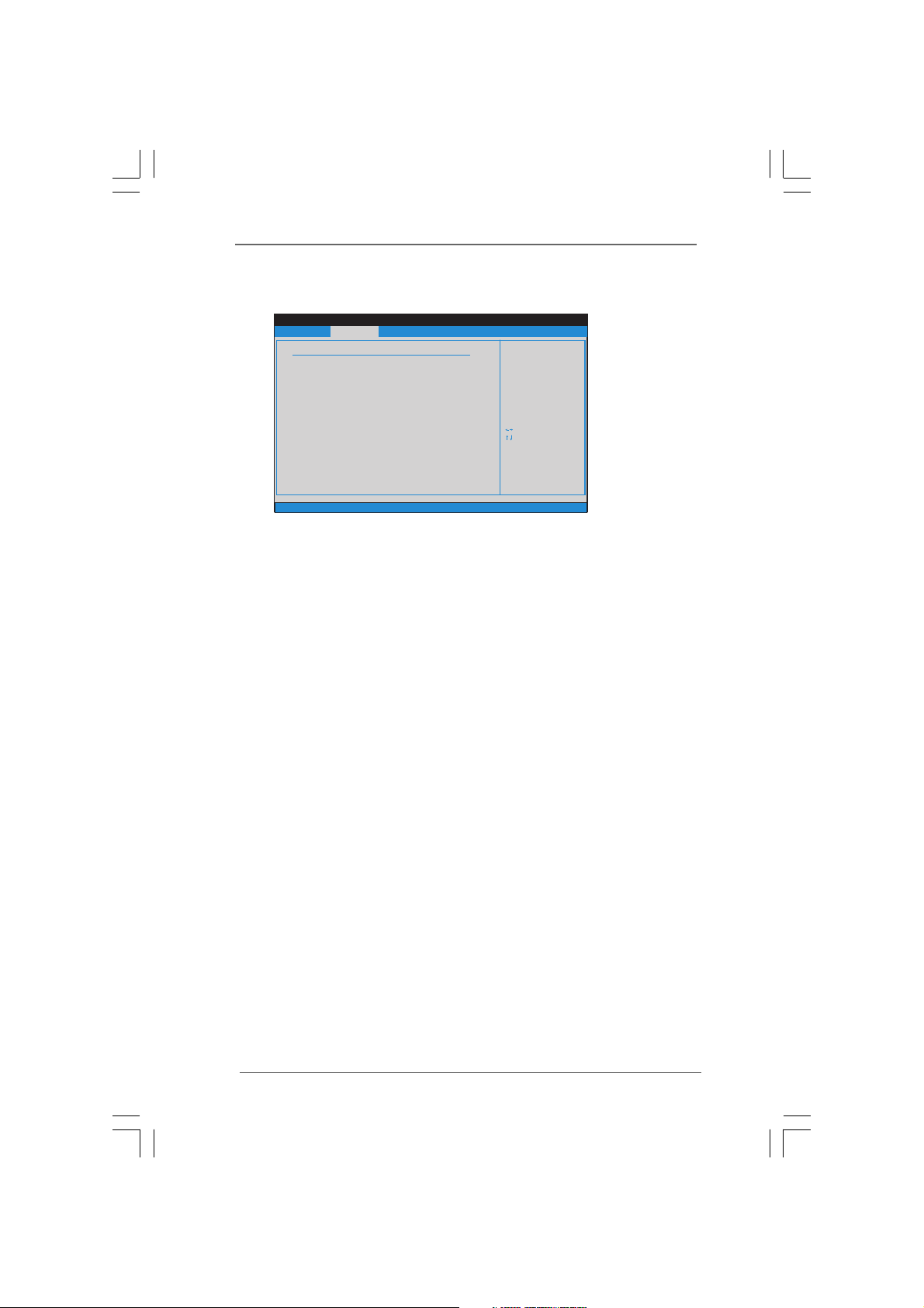
Chipset ConfigurationChipset Configuration
3.4.2
Chipset Configuration
3.4.23.4.2
Chipset ConfigurationChipset Configuration
Internal Graphics Mode Select
If you select [Auto], the onboard VGA will be automatically disabled when
you install VGA card; the onboard VGA will be enabled without the installa-
tion of any add-on VGA card. If you select [Enabled, 8MB] or [Enabled,
1MB], the onboard VGA will be enabled.
DVMT Mode Select
Use this option to adjust DVMT mode. Configuration options: [Fixed Mode],
[DVMT Mode] and [Fixed+DVMT Mode]. The default value is [DVMT Mode].
DVMT (Dynamic Video Memory Technology) is an architecture that offers
breakthrough performance for the motherboard through efficient memory
utilization. In Fixed mode, a fixed-size fragment of the system memory is
allocated to the graphics core. In DVMT mode, the graphics driver allocates
memory as needed for running graphics applications and is cooperatively
using this memory with other system components. In Fixed+DVMT mode,
the graphics processor gets a fixed-size chunk of 64MB of memory and up
to 64MB of dynamically-allotted memory. This mode guarantees that at least
64MB of memory is available to the graphics core, with a possibility to
increase this amount to 128MB, if necessary. This item will not be used
under Windows® VistaTM OS because the driver will intelligently detect
physical memory available and allocate necessary video memory.
DVMT/FIXED Memory
You are allowed to adjust the shared memory size in this item if you set
DVMT Mode Select as [DVMT Mode]. Configuration options: [64MB], [128MB]
and [Maximum DVMT].
Onboard HD Audio
Select [Enabled] or [Disabled] for the onboard HD Audio feature.
2424
24
2424
Page 25
OnBoard Lan 1
BIO S SETUP UT ILITY
ACP I Confi gurat ion
Set t he powe rs tate
aft er an unex pecte d
AC/ Power lo ss.
Sel ect Scre en
Sel ect Ite m
+- Ch ange Op tion
F1 Ge neral H elp
F9 Lo ad Defa ults
F10 S ave and E xit
ESC E xit
v02 .54 (C) C opyri ght 198 5-200 5, A meric an Mega trends , Inc.
Adv anced
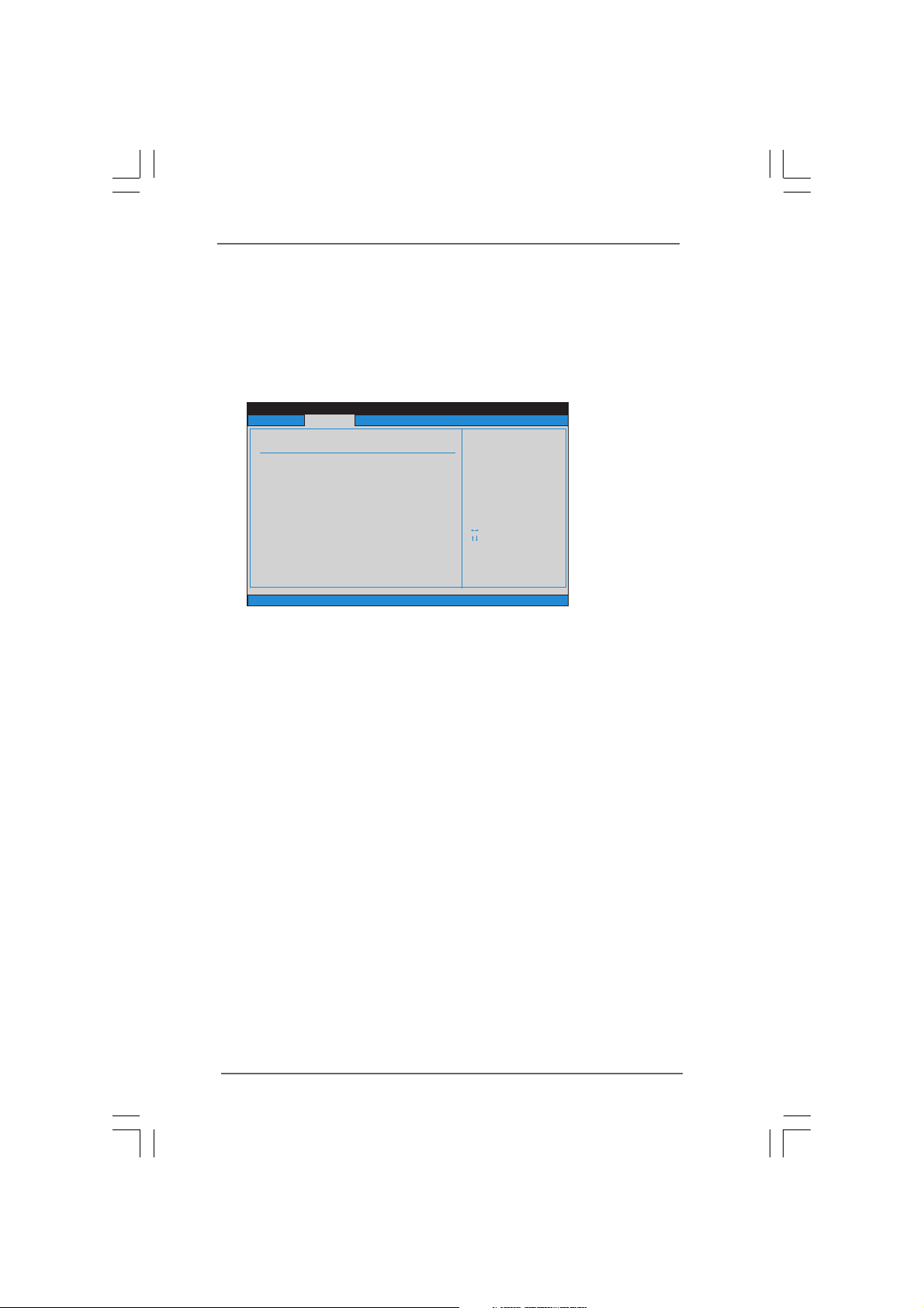
Res tore on AC/ P ower Lo ss
Rin g-In Po wer O n
PCI D evice s Power On
RTC Ala rm Powe r O n
ACP I HPET Table
[Po wer Off]
[Di sable d]
[Di sable d]
[Di sable d]
[Di sable d]
This allows you to enable or disable the “OnBoard Lan 1” feature.
OnBoard Lan 2
This allows you to enable or disable the “OnBoard Lan 2” feature.
3.4.33.4.3
AA
3.4.3
3.4.33.4.3
CPI ConfigurationCPI Configuration
A
CPI Configuration
AA
CPI ConfigurationCPI Configuration
Restore on AC/Power Loss
This allows you to set the power state after an unexpected AC/ Power
loss. If [Power Off] is selected, the AC/ Power remains off when the power
recovers. If [Power On] is selected, the AC/ Power resumes and the
system starts to boot up when the power recovers. User can enable "Re
store AC/ power off." The default value is [Power Off].
Ring-In Power On
Use this item to enable or disable Ring-In signals to turn on the system from
the power-soft-off mode.
PCI Devices Power On
Use this item to enable or disable PCI devices to turn on the system from
the power-soft-off mode.
RTC Alarm Power On
Use this item to enable or disable RTC (Real Time Clock) to power on the
system.
2525
25
2525
Page 26
BIO S SETUP U TILIT Y
Pri mary ID E Maste r
Sel ect the t ype
of de vice co nnect ed
to th e syste m.
Sel ect Scre en
Sel ect Ite m
+- Ch ange Op tion
F1 Ge neral H elp
F9 Lo ad Defa ults
F10 S ave and E xit
ESC E xit
v02 .54 (C) C opyri ght 198 5-200 5, A meric an Mega trend s, Inc.
Adv anced
Type
LBA/ Large M ode
Bloc k (Mult i-Sec tor Tra nsfer )
PIO Mo de
DMA M ode
S . M . A. R . T .
32Bi t Data Transf er
[Aut o]
[Aut o]
[Aut o]
[Aut o]
[Aut o]
[Dis abled ]
[Ena bled]
:No t Detec ted
Dev ice
BIO S SETUP U TILIT Y
Sto rage Co nfigu ratio n
Set [ Compa tible ]
whe n Legac y OS
(MS -DOS, W in NT)
dev ice is us ed.
Set [ Enhan ced]
whe n Nativ e OS
(Win 2000 / XP )
is us ed.
v02 .54 (C) C opyri ght 198 5-200 5, A meric an Mega trend s, Inc.
Adv anced
ATA/ID E Confi gurat ion
[En hance d]
Sel ect Scre en
Sel ect Ite m
+- Ch ange Op tion
F1 Ge neral H elp
F9 Lo ad Defa ults
F10 S ave and E xit
ESC E xit
Sel ect Scre en
Sel ect Ite m
+- Ch ange Op tion
F1 Ge neral H elp
F9 Lo ad Defa ults
F10 S ave and E xit
ESC E xit
IDE 1 Maste r
IDE 1 Slave
SATAII _1
SATAII _2
SATAII _3
SATAII _4
[No t Detec ted]
[No t Detec ted]
[No t Detec ted]
[No t Detec ted]
[No t Detec ted]
[No t Detec ted]
ACPI HPET Table
Use this item to enable or disable ACPI HPET Table. The default value is
[Disabled]. Please set this option to [Enabled] if you plan to use this
motherboard to submit Windows® VistaTM certification.
3.4.43.4.4
Storage ConfigurationStorage Configuration
3.4.4
Storage Configuration
3.4.43.4.4
Storage ConfigurationStorage Configuration
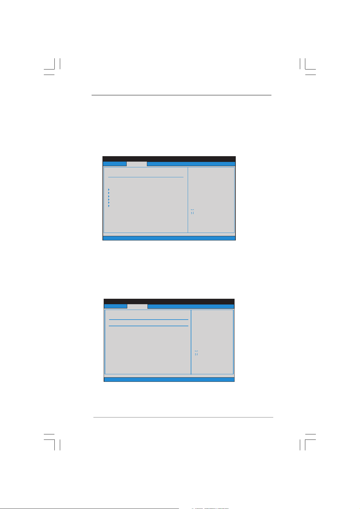
ATA/IDE Configuration
Please select [Compatible] when you install legacy OS (Windows® NT). If
native OS (Windows® 2000 / XP / VistaTM) is installed, please select
[Enhanced].
IDE Device Configuration
You may set the IDE configuration for the device that you specify. We will
use the “Primary IDE Master” as the example in the following instruction.
2626
26
2626
Page 27
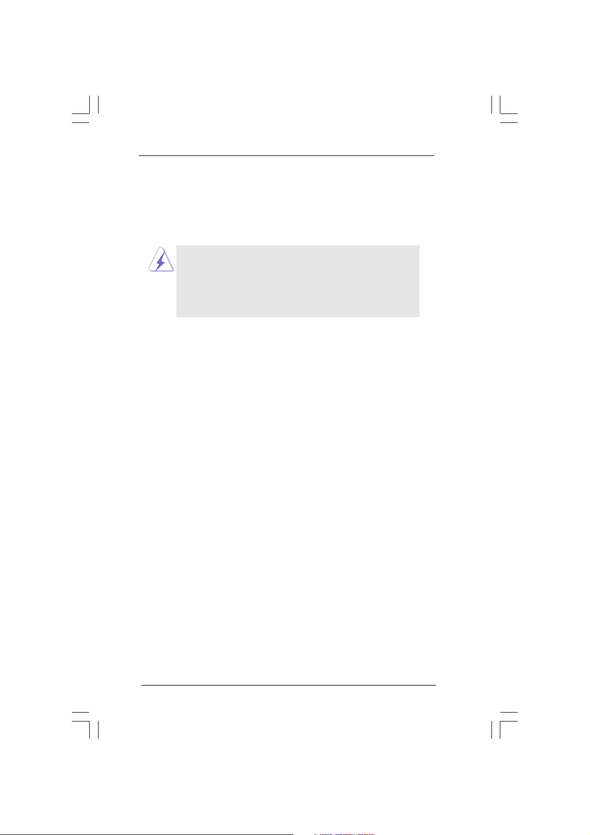
TYPE
Use this item to configure the type of the IDE device that you specify. Con-
figuration options: [Not Installed], [Auto], [CD/DVD], and [ARMD].
[Not Installed]: Select [Not Installed] to disable the use of IDE device.
[Auto]: Select [Auto] to automatically detect the hard disk drive.
After selecting the hard dissk information into BIOS, use a disk
utility, such as FDISK, to partition and format the new IDE hard
disk drives. This is necessary for write or read data from the hard
Make sure to set the partition of the Primary IDE hard disk drives to
active.
LBA/Large Mode
Use this item to select the LBA/Large mode for a hard disk > 512 MB under
DOS and Windows; for Netware and UNIX user, select [Disabled] to
disable the LBA/Large mode.
Block (Multi-Sector Transfer)
The default value of this item is [Auto]. If this feature is enabled, it will en-
hance hard disk performance by reading or writing more data during each
transfer.
PIO Mode
Use this item to set the PIO mode to enhance hard disk performance by
optimizing the hard disk timing.
DMA Mode
DMA capability allows the improved transfer-speed and data-integrity for
compatible IDE devices.
S.M.A.R.T.
Use this item to enable or disable the S.M.A.R.T. (Self-Monitoring, Analysis,
and Reporting Technology) feature. Configuration options: [Disabled], [Auto],
[Enabled].
32-Bit Data Transfer
Use this item to enable 32-bit access to maximize the IDE hard disk data
transfer rate.
2727
27
2727
Page 28
3.4.53.4.5
BIO S SETUP U TILIT Y
Con figur e Super IO Ch ipset
All ow BIOS t o Selec t
Ser ial Por t Base
Add resses .
Sel ect Scre en
Sel ect Ite m
+- Ch ange Op tion
F1 Ge neral H elp
F9 Lo ad Defa ults
F10 S ave and E xit
ESC E xit
v02 .54 (C) C opyri ght 198 5-200 3, A meric an Mega trend s, Inc.
Adv anced
Ser ial Por t A ddress
[3F 8 / IRQ4]
BIO S SETUP U TILIT Y
USB C onfig urati on
To enab le or dis able
the o nboar d USB
con trolle rs.
Sel ect Scre en
Sel ect Ite m
+- Ch ange Op tion
F1 Ge neral H elp
F9 Lo ad Defa ults
F10 S ave and E xit
ESC E xit
v02 .54 (C) C opyri ght 198 5-200 5, A meric an Mega trend s, Inc.
Adv anced
USB C ontrol ler
USB 2 .0 Supp ort
Leg acy USB S uppor t
[En abled ]
[En abled ]
[En abled ]
Super IO ConfigurationSuper IO Configuration
3.4.5
Super IO Configuration
3.4.53.4.5
Super IO ConfigurationSuper IO Configuration
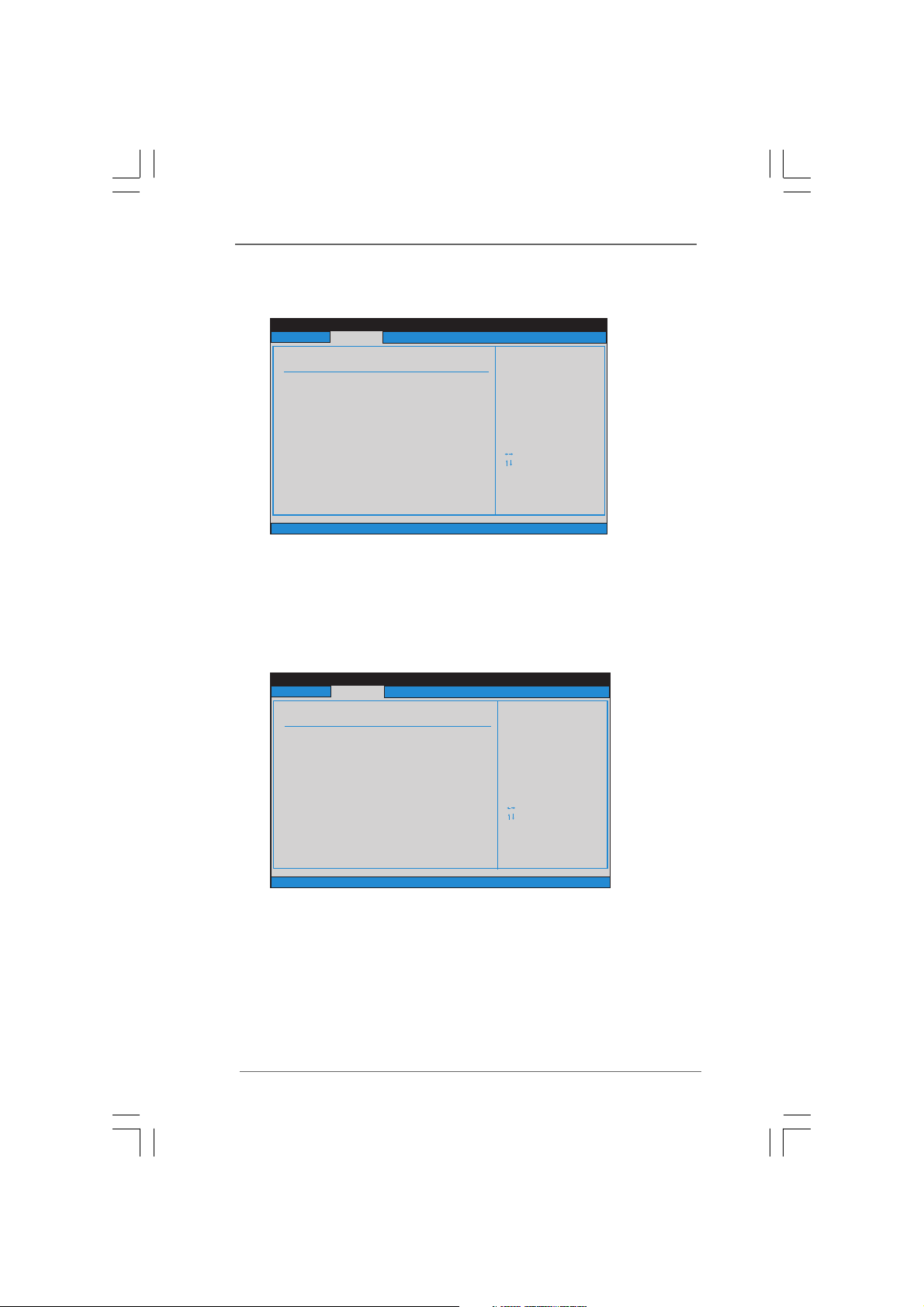
Serial Port Address
Use this item to set the address for the onboard serial port or disable it.
Configuration options: [Disabled], [3F8 / IRQ4], [2F8 / IRQ3], [3E8 / IRQ4],
[2E8 / IRQ3].
3.4.63.4.6
USB ConfigurationUSB Configuration
3.4.6
USB Configuration
3.4.63.4.6
USB ConfigurationUSB Configuration
2828
28
2828
USB Controller
Use this item to enable or disable the use of USB controller.
USB 2.0 Support
Use this item to enable or disable the USB 2.0 support.
Page 29
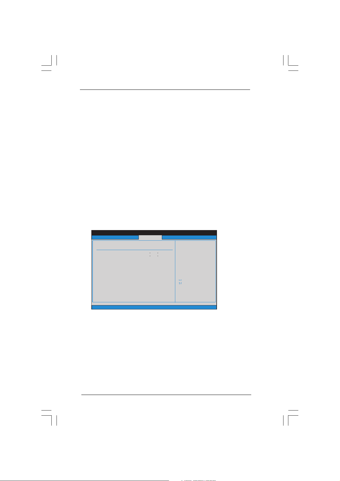
Legacy USB Support
BIO S SETUP U TILIT Y
Har dware H ealth E vent Mo nitor ing
Sel ect Scre en
Sel ect Ite m
F1 Ge neral H elp
F9 Lo ad Defa ults
F10 S ave and E xit
ESC E xit
v02 .54 (C) C opyri ght 198 5-200 3, A meric an Mega trend s, Inc.
CPU Tem perat ure
M / B Tempe ratur e
NB Fa n Speed
Sys tem Fan S peed
Vco re
+ 3.3 0V
+ 5.0 0V
+ 12. 00V
: 34 C / 93 F
: 421 8 RPM
: 272 1 RPM
: 1.2 08V
: 3.3 28V
: 4.8 48V
: 12. 460V
: 31 C / 87 F
Mai n Smart Ad vance d
Boo t Secur ity Exi t
H/W M onito r
Fan c onfig urati on
mod e setti ng
Sys tem Fan S ettin g [Fu ll on]
Use this option to select legacy support for USB devices. There are four
configuration options: [Enabled], [Auto], [Disabled] and [BIOS Setup
Only]. The default value is [Enabled]. Please refer to below descriptions
for the details of these four options:
[Enabled] - Enables support for legacy USB.
[Auto] - Enables legacy support if USB devices are connected.
[Disabled] - USB devices are not allowed to use under legacy OS and
BIOS setup when [Disabled] is selected. If you have USB compatibility
issue, it is recommended to select [Disabled] to enter OS.
[BIOS Setup Only] - USB devices are allowed to use only under BIOS
setup and Windows / Linux OS.
3.53.5
Hardware Health Event Monitoring ScreenHardware Health Event Monitoring Screen
3.5
Hardware Health Event Monitoring Screen
3.53.5
Hardware Health Event Monitoring ScreenHardware Health Event Monitoring Screen
In this section, it allows you to monitor the status of the hardware on your system,
including the parameters of the CPU temperature, motherboard temperature, CPU
fan speed, chassis fan speed, and the critical voltage.
System Fan Setting
The system fan improves the air circulation of the computer's enclosure.
Use this option to adjust the fan speed. The default value is [Full On].
Configuration options: [Full On], [Manual]. Manual allow user to set Target
Fan Speed from level 1-9
2929
29
2929
Page 30
3.63.6
BIO S SETUP U TILIT Y
Mai n Smart Advan ced H/ WM onito r
Sec urity E xit
Boo t Setti ngs
Con figure S ettin gs
dur ing Sys tem Boo t.
Sel ect Scre en
Sel ect Ite m
Ent er Go t o Sub Scre en
F1 Ge neral H elp
F9 Lo ad Defa ults
F10 S ave and E xit
ESC E xit
v02 .54 (C) C opyri ght 198 5-200 5, A meric an Mega trend s, Inc.
Boo t
Boo t Setti ngs Con figur ation
BIO S SETUP U TILIT Y
Boo t Setti ngs Con figur ation
To enab le or dis able th e
boo t from onb oard LA N
fun ction
Sel ect Scre en
Sel ect Ite m
+ - Cha nge Opt ion
F1 Ge neral H elp
F9 Lo ad Defa ults
F10 S ave and E xit
ESC E xit
v02 .54 (C) C opyri ght 198 5-200 3, A meric an Mega trend s, Inc.
Boo t
Boo tup Num -Lock
[On ]
Boo t From Onb oard LA N
[Di sable d]
Boot ScreenBoot Screen
3.6
Boot Screen
3.63.6
Boot ScreenBoot Screen
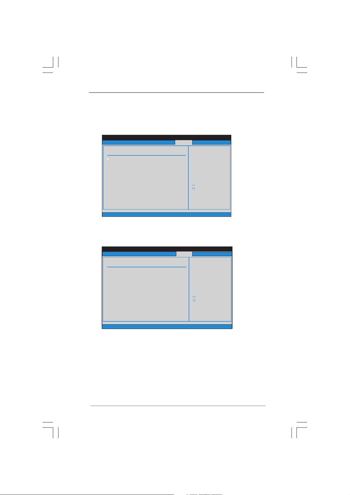
In this section, it will display the available devices on your system for you to configure
the boot settings and the boot priority.
3.6.13.6.1
Boot Settings ConfigurationBoot Settings Configuration
3.6.1
Boot Settings Configuration
3.6.13.6.1
Boot Settings ConfigurationBoot Settings Configuration
3030
30
3030
Boot From Onboard LAN
Use this item to enable or disable the Boot From Onboard LAN
feature.
Boot up Num-Lock
Use this item to turn on or off the numeric keypad feature.
Page 31
BIO S SETUP U TILIT Y
Mai n Smart Ad vance d H/W Mon itor Bo ot Secu rity
Exi t syste m setup
aft er s aving t he
cha nges.
F10 k ey can be u sed
for t his ope ratio n.
Sel ect Scre en
Sel ect Ite m
Ent er Go t o Sub Scre en
F1 Ge neral H elp
F10 S ave and E xit
ESC E xit
F9 Lo ad Defa ults
v02 .54 (C) C opyri ght 198 5-200 5, A meric an Mega trend s, Inc.
Exi t
Sav e Chang es and Ex it
Dis card Ch anges a nd Exit
Dis card Ch anges
Exi t Optio ns
Woul d you lik e to save c urrent s ettin g
use r d efaul ts ?
Sav e 1st Use r D efaul ts
Sav e 2nd Use r D efaul ts
Sav e 3rd Use r D efaul ts
Loa d 1st Use r D efaul ts
Loa d 2nd Use r D efaul ts
Loa d 3rd Use r D efaul ts
BIO S SETUP U TILIT Y
Mai n Smart Ad vance d H/W Mon itor Bo ot
Exi t
Ins tall or C hange t he
pas sword .
Sel ect Scre en
Sel ect Ite m
Ent er Ch ange
F1 Ge neral H elp
F10 S ave and E xit
ESC E xit
F9 Lo ad Defa ults
v02 .54 (C) C opyri ght 198 5-200 5, A meric an Mega trend s, Inc.
Sec urity
Cha nge Sup ervis or P asswo rd
Cha nge Use r P asswo rd
Sec urity S ettin gs
Sup ervis or P asswo rd : Not In stall ed
Use r P asswo rd : Not In stall ed
3.73.7
Security ScreenSecurity Screen
3.7
Security Screen
3.73.7
Security ScreenSecurity Screen
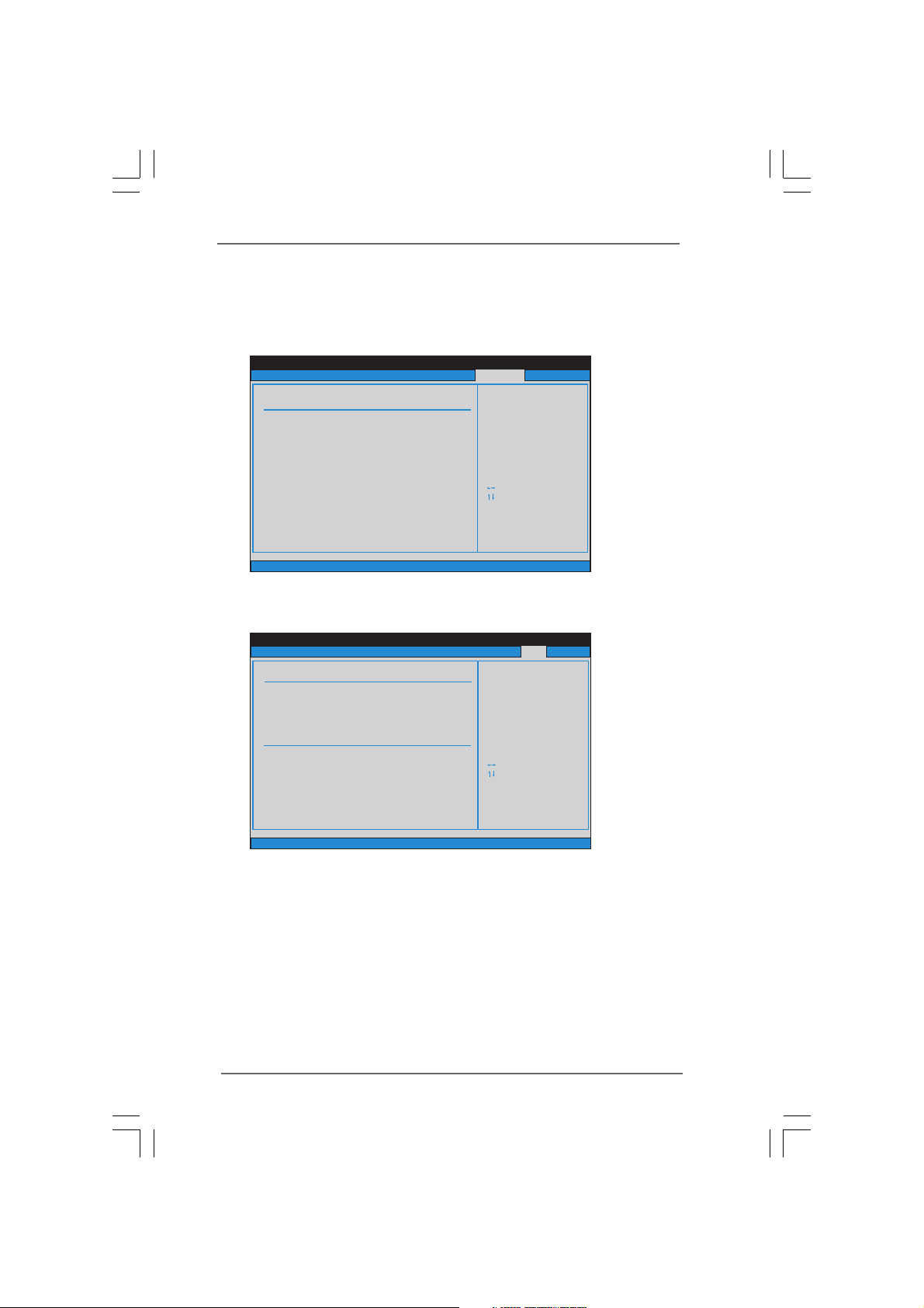
In this section, you may set or change the supervisor/user password for the system.
For the user password, you may also clear it.
3.8 3.8
Exit Screen Exit Screen
3.8
Exit Screen
3.8 3.8
Exit Screen Exit Screen
Save Changes and Exit
When you select this option, it will pop-out the following message, “Save
configuration changes and exit setup?” Select [OK] to save the changes and
exit the BIOS SETUP UTILITY.
Discard Changes and Exit
When you select this option, it will pop-out the following message, “Discard
changes and exit setup?” Select [OK] to exit the BIOS SETUP UTILITY with-
out saving any changes.
3131
31
3131
Page 32

Discard Changes
When you select this option, it will pop-out the following message, “Discard
changes?” Select [OK] to discard all changes.
Would you like to save current setting user defaults?
In this option, you are allowed to load and save three user defaults
according to your own requirements.
3232
32
3232
Page 33

Chapter 4 SofChapter 4 Sof
Chapter 4 Sof
Chapter 4 SofChapter 4 Sof
4.1 Install Operating System
This motherboard supports various Microsoft® Windows® operating systems: XP /
VistaTM. Because motherboard settings and hardware options vary, use the setup
procedures in this chapter for general reference only. Refer to your OS documenta-
tion for more information.
4.2 Support CD Information
The Support CD that came with the motherboard contains necessary drivers and
useful utilities that enhance the motherboard features.
4.2.1 Running The Support CD
To begin using the support CD, insert the CD into your CD-ROM drive. The CD
automatically displays the Main Menu if “AUTORUN” is enabled in your computer.
If the Main Menu did not appear automatically, locate and double click on the file
“ASSETUP.EXE” from the BIN folder in the Support CD to display the menus.
4.2.2 Drivers Menu
The Drivers Menu shows the available devices drivers if the system detects
installed devices. Please install the necessary drivers to activate the devices.
4.2.3 Utilities Menu
The Utilities Menu shows the applications software that the motherboard
supports. Click on a specific item then follow the installation wizard to install it.
tware Supportware Suppor
tware Suppor
tware Supportware Suppor
tt
t
tt
4.2.4 Contact Information
If you need to contact huperLab or want to know more about huperLab, welcome
to visit huperLab’s website at
dealer for further information.
http://www.huperlab.com; or you may contact your
3333
33
3333
Page 34
Chapter 5 Chapter 5
Chapter 5
Chapter 5 Chapter 5
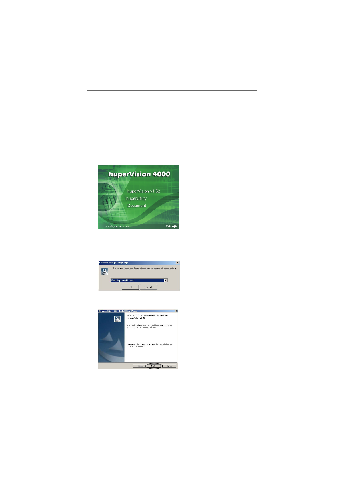
5.1 Easy Steps to install software
Follow the steps 1-7 to install huperVision.
1. Insert huperVision installation CD. Auto Run will start up as below.
2. Press [Install huperVision] button to start huperVision installation program.
Then select installation language from Setup Language dialog and press [OK]
button to begin installation.
huperVision SofhuperVision Sof
huperVision Sof
huperVision SofhuperVision Sof
tware Installatiotware Installatio
tware Installatio
tware Installatiotware Installatio
nn
n
nn
Start installion, press [Next] to continue.
3434
34
3434
Page 35
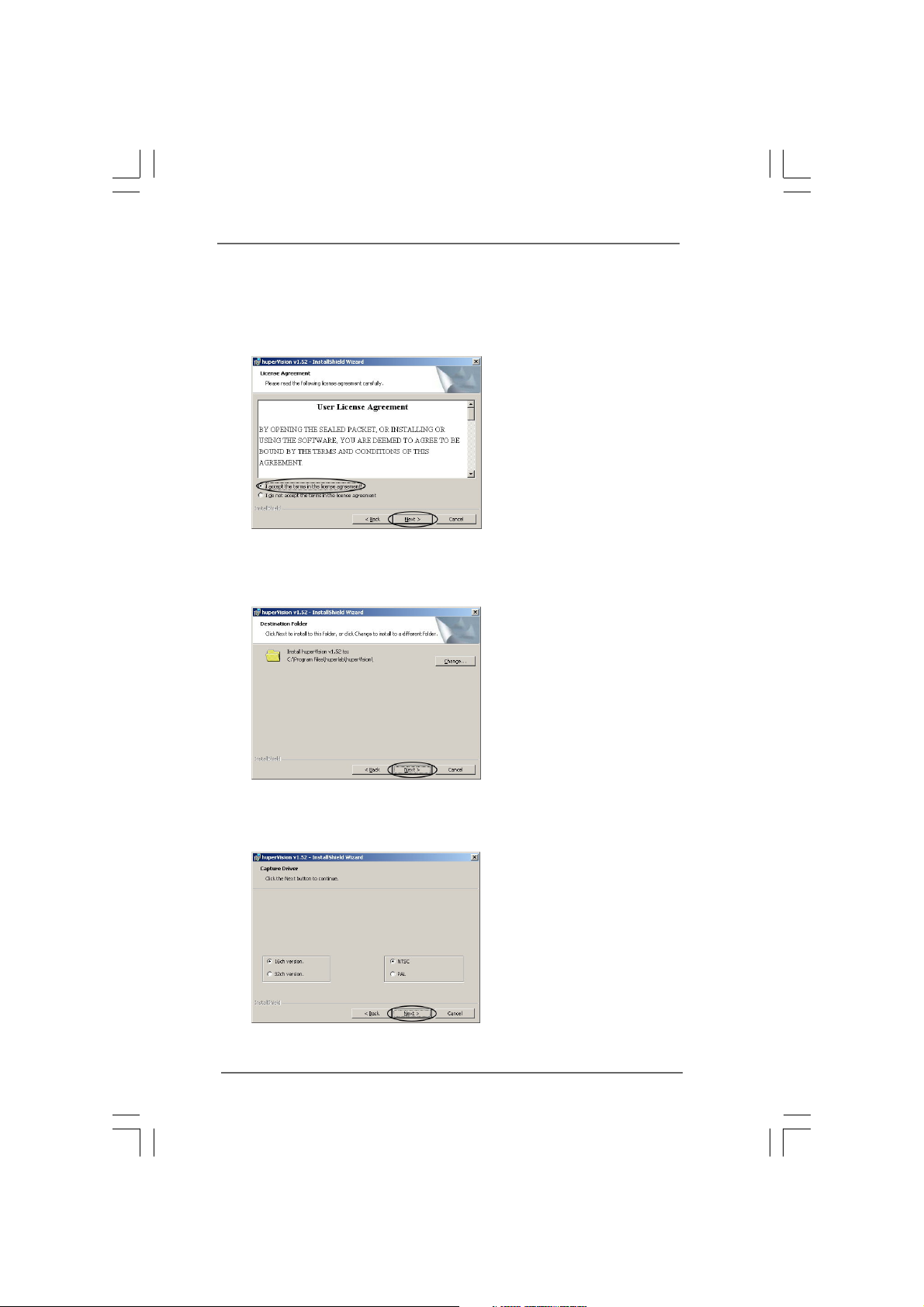
3. Please choose [I accept the terms in the license agreement] and then
press [Next] to continue.
4. Choose destination folder. The default path for installation is C:\Program
Files\huperVision\. Press [Change...] if you want to install to another folder.
Press [Next] to continue if the destination folder is confirmed.
5. Select Capture Card Driver. Please select 16ch version for Gaia 404 / Gaia 408 /
Gaia 416. Then choose correct Video standard (NTSC/PAL) and press [Next] to
continue.
3535
35
3535
Page 36
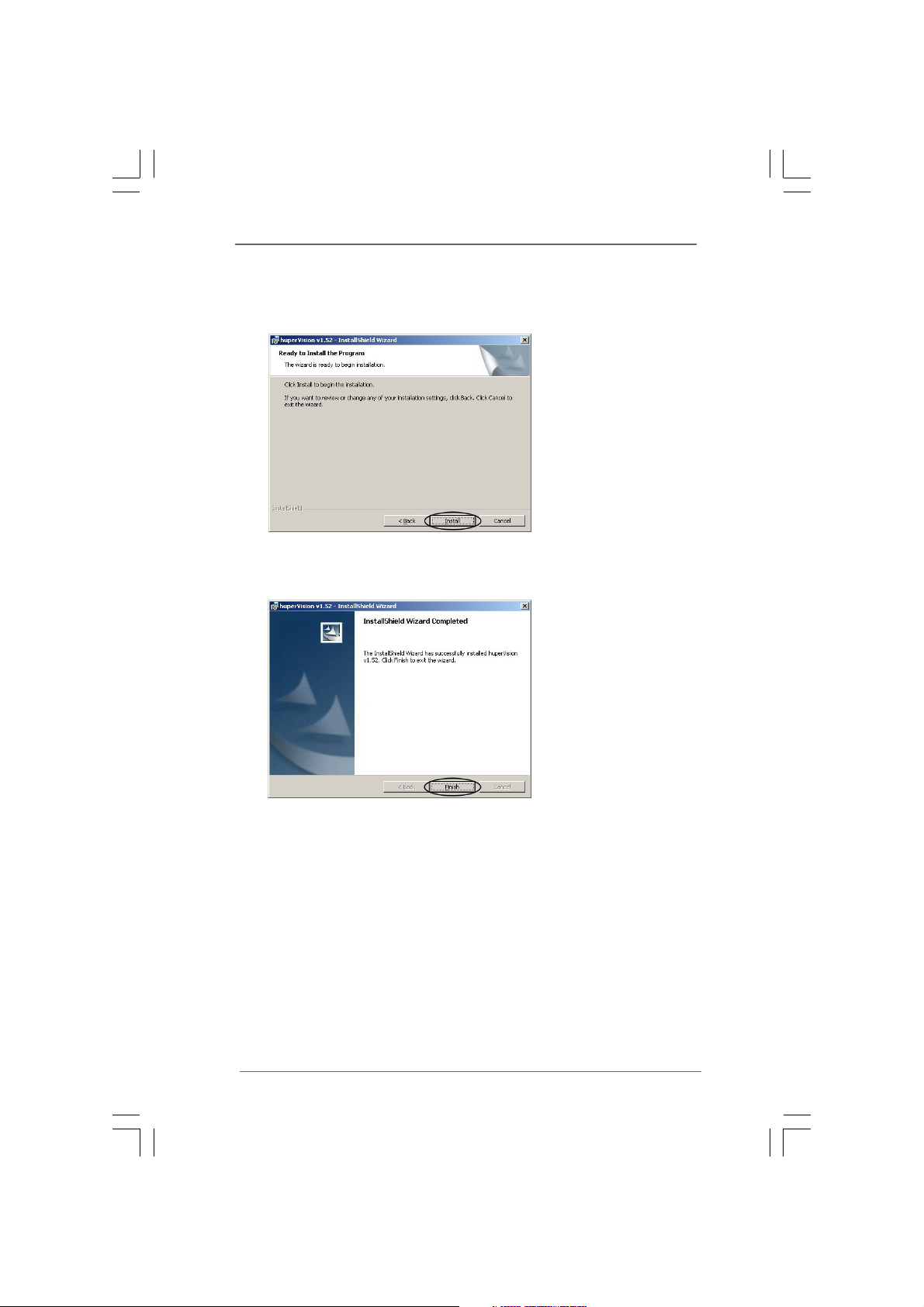
6. Press [Install] to start installing program & capture card driver. Press [Back] if you
want to change installation options.
7. Press [Finish] to end installation. You may probably need a reboot to initial
huperVision site server program.
3636
36
3636
Page 37
5.2 Star5.2 Star
5.2 Star
5.2 Star5.2 Star
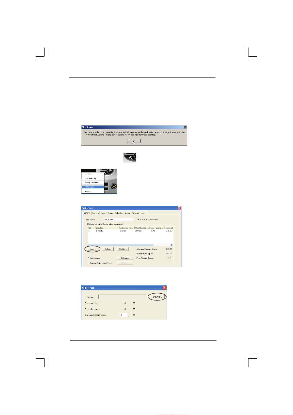
Follow the steps below to start recording.
1. Manually reboot after installation, huperVision site server program is launching
with a pop-up warning message to notify that you have not assigned a recording
path.
2. Press the [Hammer] button & select [Preferences...] to display Prefer-
ences General page.
3. Press the [Add...] button to add a new folder to store your recording data files.
t Rt R
ecording Instructionecording Instruction
t R
ecording Instruction
t Rt R
ecording Instructionecording Instruction
4. Press [Browser...] button in the Add Storage dialog box.
3737
37
3737
Page 38
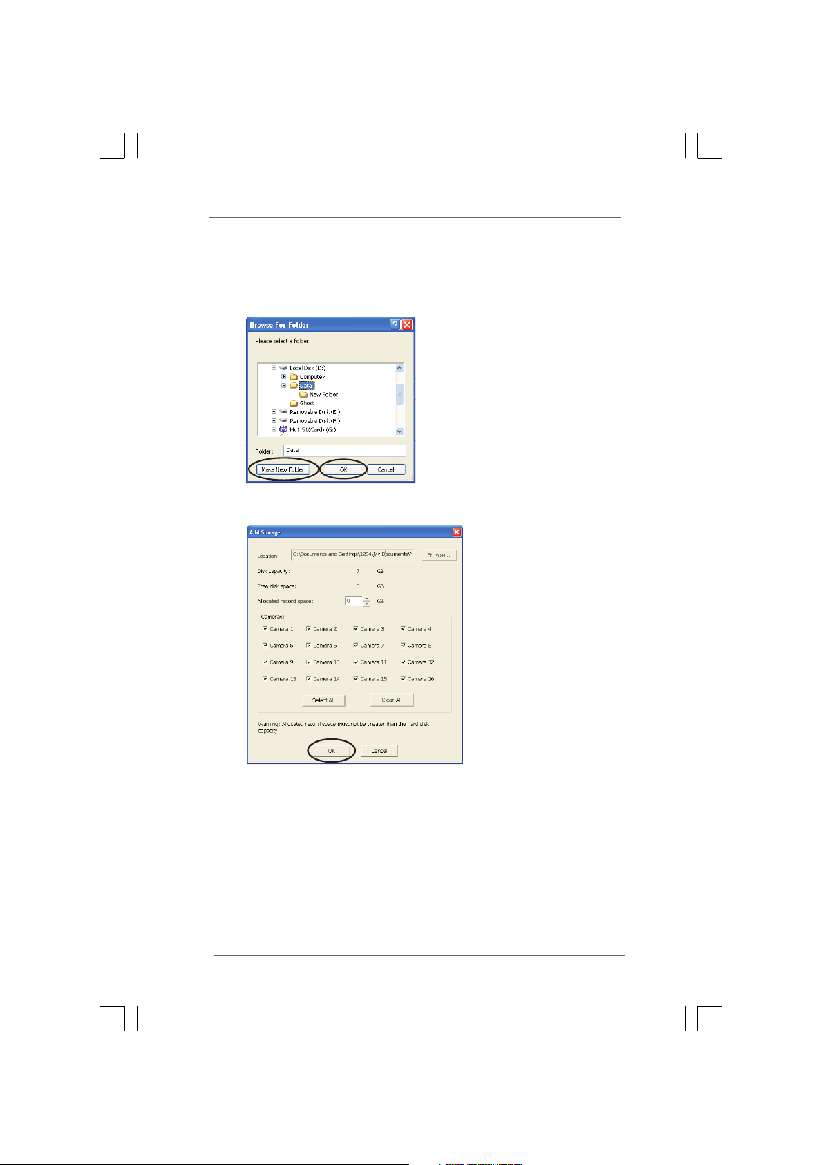
5. Set storage location in existed folder or create new folder. To create new folder,
select a drive or folder then press[Make New Folder}. Select target location and
press [OK] to set storage path.
6. After setting storage location, press[OK] button to save.
Note:
Please keep the all 16 cameras be checked even if you don't have that much cameras.
Please also do NOT change the allocated record space value by its automatic decision.
3838
38
3838
Page 39
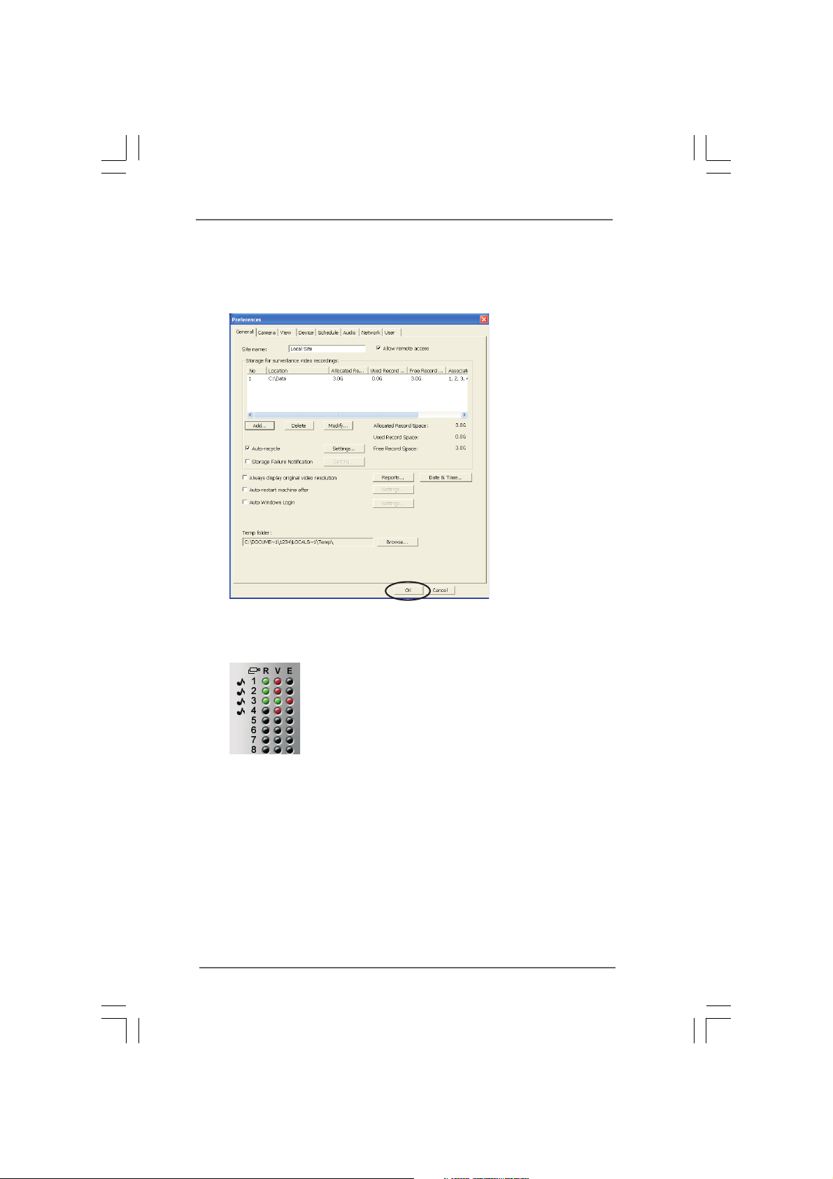
7. After create the folder, press the [OK] button of the Preference page to finish
settings.
8. The R LED turns green at upper right side, indicates that available channels are
recording now.
3939
39
3939
Page 40
5.3 Playback R5.3 Playback R
5.3 Playback R
5.3 Playback R5.3 Playback R
Follow the steps 1-7 to start recording.
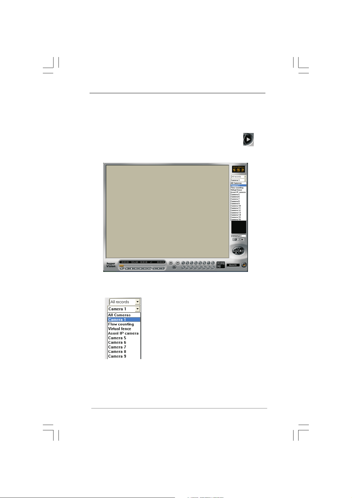
1. Launch the huperVision Record Player program by clicking the icon
2. Record Player pop up as below while site server still working in the background.
ecordings Instructionecordings Instruction
ecordings Instruction
ecordings Instructionecordings Instruction
3. Select playback channel from camera list or All Cameras.
4040
40
4040
Page 41

4. Select a time mark from list to load video records.
5. After loading (running progress bar) video, press Play button to start playing
selected recordings.
6. Repeat from Step3 to Step5 if want to playback different channel.
7. Press [Power off] button to exit Record Player and back to site server.
Note:
Press this Power off button will NOT close the running huperVision site server.
There is also a protection for accident press the huperVision site server power button,
a confirm dialog box will pop up before shutting down huperVision site server main
program.
Now you are ready to use huperVision IVS system, for more operation guide on Intel-
ligent Video Functions, please refer to full Users Manual.
To find User’s Manual, insert installation CD and press [Document] >> [User’s
Manual] in auto-run panel.
The Acrobat Reader program is included in the Installation CD under
\English\Doc\aar.exe
4141
41
4141
 Loading...