

Page 1

GSM Gate, Barrier, Shutter, Garage Door and Door opener
Open gate or garage door with a FREE call from your mobile phone !
Remote switching machines with a FREE call from your mobile phone !
GSM Gate Opener
GSM Remote Switch
RTU5015 Plus
User Manual
Ver 1.6A Date Issued: 2016-08-01
All rights reserved by HUOBEI ELECTRONICS
Page 2
About RTU5015 Plus:
The GSM Gate Opener RTU5015Plus is a very simple device which can be used for authorized door access, controlling
gates, switching of remote equipments, car parking systems. Actually the GSM Gate Opener RTU5015Plus can also be
used in places where require turning ON/OFF your system, machines, equipments remotely with a FREE call from your
mobile phone and protect your assets.
Just dial from Authorized User number then the Barrier and doors are opened, or the machine are turn on or off by the
GSM Gate Opener. There are no call costs, the GSM Gate Opener rejects the call from authorized number then carries
out the turn ON/OFF action.
Moreover, the RTU5015Plus has 2 digital inputs for alarm inputs, when any one of the inputs triggered, will send SMS
Alert the to owners immediately, in the meanwhile, the RTU5015Plus start the siren+ (DC12V) out for 5 seconds. This is
very useful if you need protect your assets with low cost solution.
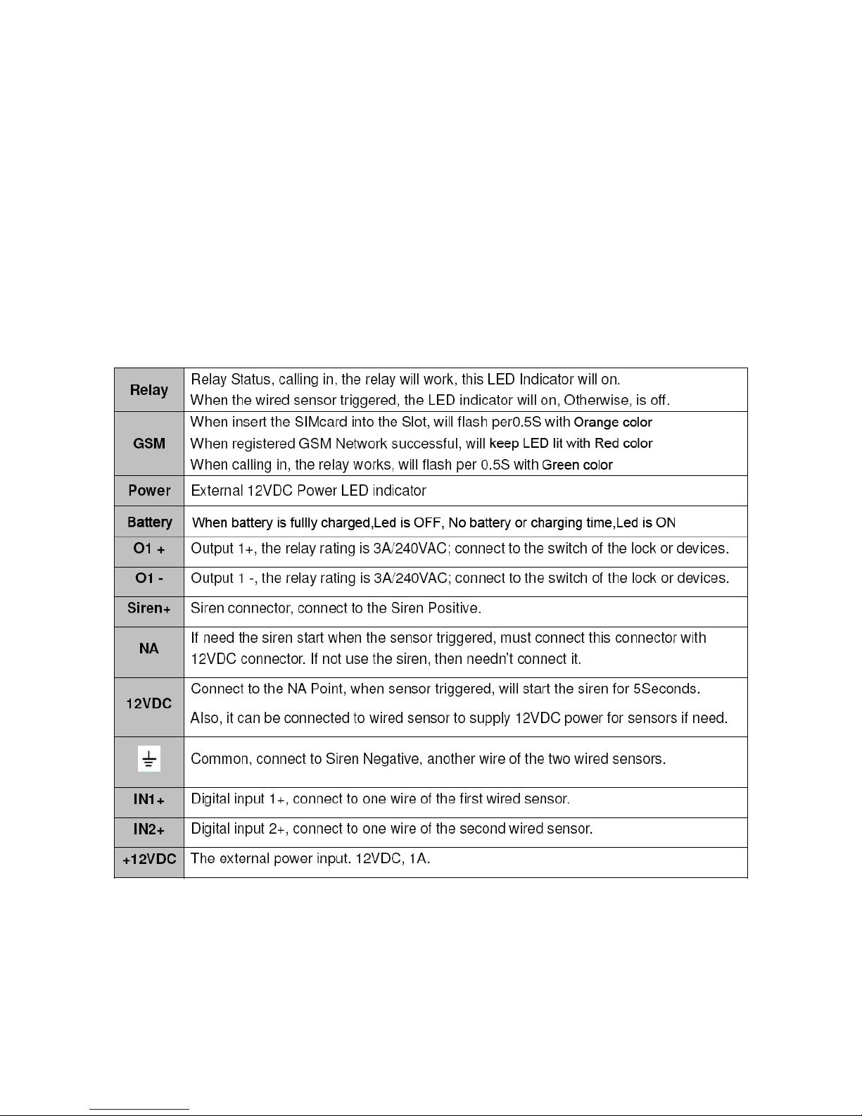
The Device LEDs and terminal descriptions are the following:
Quick Start to Use:
1. Insert the SIM card from the slide slot and connect the GSM antenna
2. Power on the device with DC12V and the “Power” Led will be lit
3. “GSM” Led will start to flash around 20 seconds,then will keep lit
4. Use your mobile phone to call the SIM card number inside the device,if the device can reject your
calling,that means the device is connected to the GSM net successfully.
Page 3

The SMS commands used in the GSM Gate Opener are the following:
1. About password
1.1 Setup New Password (Only use four digital number as the password)
pwd#PWDnewpassword#PWDnewpassword#
if successful, the unit will return: PWD SETUP OK.
For example, the original password is 1234, you want change it to 6666, then you can send the
command below: 1234#PWD6666#PWD6666#
1.2 Reset the Password
If you want to reset to factory default, then please send “RESET ” to it within 2 minutes after switch on
the RTU5015. ( After 2 minutes working,then the RTU5015 can not respond this command )
2. About Authorized numbers
2.1 Setup Authorized number
pwd#TELAuthorized Number#Serial Number#
E.g.: if you want to setup 63648495 as the first user number, and the password is 1234,then you can
send 1234#TEL63648495#001# to the RTU5015 unit.
2.2 Inquiry the Serial Number’s Authorized number
pwd#TELSerial Number?#
E.g.: If you want to know the authorized number at position 2, and the password is 1234,then you can
send 1234#TEL002?# to check it.
2.3 Search a Phone number in the RTU5015 memory
pwd#FINDphone number#
E.g.: If you forget which position of the number: 63648495, then you can send 1234#FIND63648495# to
search it in the memory.
2.4 Remove the Authorized Number
pwd#0000#Serial Number#
E.g.: if you want to remove the authorized number at position 12, and the password is 1234, then you
can send 1234#TEL#0000#012#, then will
overwrite the posion with number “0000” to remove it
3. About system parameters
3.1 Working mode selection (security mode or free control mode)
pwd#AU# This command allows only the authorized numbers can access
pwd#AA# This command allows any numbers to call the SIM number to access
pwd#AC?# Check the setting of working mode
3.2 Setup the relay close time
pwd#GOTTime# The GOT parameters should be in 0~60000 ( 0~30000 seconds )
Tips:
1. the authorized number means the one who can dial the RTU5015 unit to open it.
2.We strongly recommend that the serial number of 01 and 02 are cellphone number, because of
the alarm message only send to the first and second position numbers;
3. The Serial Number is the position to store the authorized number, from 001~999.
This command is used to setup the Relay working time when triggered. The default time is 5.0
seconds. You can change it with the GOT command. The relay closed time is half as the number
you set, e.g.: if you set pwd#GOT19#, means the relay closed 19/2=9.5Seconds.
To check the value, you can use the command pwd#GOT?#
, the unit will reply the current value.
If you want to let the relay works at switch mode, then you can set the time as 00
Page 4

4. About input alarm port
4.1 Disable the digital inputs
pwd#DA#
Tips: if you want to use the digital inputs, please enable it firstly.
4.2 Enable the digital inputs
pwd#EA#
Tips: if you enable the digital inputs function, the sensors will enter Armed status after 10minutes of the
latest dial-in. in the first 10minutes, when the sensor triggered, will not alarm, after 10minutes, the unit in
armed mode, when any sensor triggered, will start the siren (if you connected) or switch on the light(if
you connect it) around 5 seconds and send SMS to the Position 01 and 02 authorized numbers
immediately.
Siren+ output is DC12V output, it cann’t be controlled by SMS command.it only will be triggered around
5 seconds when alarm input triggered.
4.3 Inquiry Alarm Setting
pwd#AL?
Reply:
Alarm Inputs Disabled or Alarm Inputs Enabled.
Tips: Alarm Inputs Disabled means disable the digital inputs, Alarm Inputs Enabled means Enable
digital inputs.
4.4 Alarm input working mode selection
pwd#M2#
For M2 working mode,alarm would be triggered according to your KEYNO or KEYNC selection
pwd#M3#
For M3 working mode,Alarm input status is changed,then will trigger the alarm
4.5 Modify the digital input type (Working for M2 mode)
pwd#KEYNC#
Modify the digital input type as NC; if the sensor you used with this unit is NC, then you should set the
unit as NC type.
pwd#KEYNO#
Modify the digital input type as NO; if the sensor you used with this unit is NO, then you should set the
unit as NO type.
4.6 Alarm SMS Text presetting
Predefined your customized SMS Text message for alarm In1 and In2 (if password is 1234)
In1 Open Alarm Content: 1234#TEXT1Owsd1Openalarm#
In1 Close Alarm Content: 1234#TEXT1Cwsd1Closealarm#
In2 Open Alarm Content: 1234#TEXT2Owsd2Openalarm#
In2 Close Alarm Content: 1234#TEXT2Cwsd2Closealarm#
wsd1Openalarm, wsd1Closealarm, wsd2Openalarm, wsd2Closealarm are the Customized Message
text to be sent when alarm happen
4.7 Check the Alarm SMS Text
pwd#ALARMTEXT?#
5. About Customized SMS Command
Tips: Normally you can use the phone calling to control the device,but sometimes maybe you need to
use the SMS to control the output with a temporarily timer control or temporarily ON or OFF ,and you
don’t nee to change the device setting.
Customize Relay Output ON Command: 1234#ON-TEXT=XXXXXX
Customize Relay Output OFF Command: 1234#OFF-TEXT=XXXXX
Customize Relay Ouput Timer Control: 1234#TOG-TEXT=XXXXX
Page 5

E.g.: If you can setup the Timer control command: 1234#TOG=asm#, then the authorized numbers can
only send SMS: asm ,device will be triggered with the GOT timer,and if want to trigger the output with a
temporarily Timer,then just send “ asm=20 “, the output will be trigged for 10 seconds
For customized SMS command, no need to put the password in front of the Text.
If you forget the SMS text,then use the command to check it:
pwd#QUE-TEST?
6. About the Backup battery for power off alarm
RTU5015Plus has a built-in Rechargeable lithium battery,that is only used for Main power supply failure
alarm,Every time when power off ,then RTU5015 plus will send out the alarm SMS and then it will power
off the GSM module to save the battery power,so when during main power supply off,you can not control
it or send the SMS.During power failure, RTU5015Plus still monitor the alarm input port,if the alarm input
is triggered,it will still send the alarm SMS.
Important Tips:
When power off time over five minutes or first time to use.Only when normal power supply time is more
than 2 minutes,then battery start to work.
7. About the device status change report
For RTU5015 Standard version, that Report is limited to the relay status change.but for RTU5015Plus,
any device status change or SMS command will be reported.
pwd#N#. When device change,no report
pwd#R#. When device change,will send the SMS report to TEL01 and TEL02
To check the settings, you can use the command: pwd#M? it will return:
Relay action return SMS ON or Relay action return SMS OFF
.
8. Read the device status and the parameters
For RTU5015Plus you can use one SMS command to check the device information
pwd#STATUS?#
Device will reply as:
DEVICE:AU,EA,R,KEYNC,GOT=05.0S,CSQ=12,ACP00,M2,OUT=00
How to power off the RTU5015Plus completely when the battery connected:
Firstly Power off the DC12V for more than 6 minutes,Then quickly repeat Power ON and OFF the
DC12V for three times till all LED lights go out.
Reply SMS from device: ON-TEXT=won,OFF-TEXT=woff,TOG-TEXT=asm
Page 6

 Loading...