

Huntleigh Healthcare Sonicaid Team DM, Sonicaid Team IP, Sonicaid Team Standard, Sonicaid Team Duo User Manual

SonicaidTeam
Operator’s Manual
¤ Huntleigh HEALTHCARE Ltd 2006
All rights reserved
738311-A
February 2006

Sonicaid Team Operator’s Manual
Sonicaid™ Team is in conformity with the Medical Device
Directive (93/42/EEC) and has been subject to the conformity
assurance procedures laid down in the European Council
Directive.
2

Sonicaid Team Operator’s Manual
Contents
Contents..............................................................................................................................3
Standards compliance........................................................................................................ 6
Indications for use.............................................................................................................. 7
System Installation.............................................................................................................8
Calibration.......................................................................................................................... 8
Multiple Portable Socket Outlets...................................................................................... 9
Electromagnetic compatibility........................................................................................ 10
Copyright..........................................................................................................................11
Trademarks....................................................................................................................... 11
Note on terminology....................................................................................................... 12
Sensors..............................................................................................................................12
Addresses.......................................................................................................................... 13
1 Introduction .............................................................................................................. 15
1.1 Team fetal monitors.......................................................................................15
1.2 Main unit: front panel.................................................................................... 16
1.3 Main unit: rear panel ..................................................................................... 17
1.4 Contrast control.............................................................................................. 18
1.5 Team printer: front panel .............................................................................. 19
1.6 Team printer: rear panel................................................................................20
1.7 Team printer wedge assembly (option)........................................................ 21
1.8 Team printer to Team base unit assembly....................................................22
1.9 Team base unit to Team trolley assembly..................................................... 23
1.10 Transducers and cables................................................................................... 24
1.11 Team display panel.........................................................................................26
1.12 The Team Keypad........................................................................................... 28
2 Getting Started ......................................................................................................... 29
2.1 Summary of recording procedure ................................................................. 29
2.2 The Team printer............................................................................................31
2.3 Trace annotation ............................................................................................ 32
2.4 Loading printer paper....................................................................................34
2.5 Printer operation............................................................................................35
2.6 Team menu system.........................................................................................36
2.7 User name ....................................................................................................... 37
2.8 Date and time.................................................................................................37
2.9 Version ............................................................................................................ 38
2.10 Changing language........................................................................................ 38
2.11 Entering Patient Details................................................................................. 39
3

Sonicaid Team Operator’s Manual
Contents
3 Monitoring................................................................................................................40
3.1 Ultrasound transducers .................................................................................. 40
3.2 External Toco (contractions) transducer ....................................................... 43
3.3 Fetal ECG scalp electrode (TeamIP only)....................................................... 44
3.4 Twin heart rate monitoring...........................................................................46
3.5 Intrauterine pressure catheter (contractions)............................................... 47
3.6 Maternal Heart Rate monitoring (not available in the USA and Canada) . 47
3.7 Team connected to FetalCare or System8002............................................... 48
4 Events and Alarms..................................................................................................... 50
4.1 Recording fetal movement events ................................................................50
4.2 Actogram ........................................................................................................ 50
4.3 Recording clinical events................................................................................ 53
4.4 Alarms ............................................................................................................. 54
5 Storing Records.........................................................................................................56
5.1 Storing............................................................................................................. 56
5.2 Selecting a stored record for review ............................................................. 58
5.3 Displaying a stored record ............................................................................. 58
5.4 Printing a stored record ................................................................................. 58
5.5 Transferring a stored record to Sonicaid FetalCare or System8002 ............59
5.6 Deleting a stored record ................................................................................ 60
6 Care Printer (option)................................................................................................. 61
6.1 Overview ......................................................................................................... 61
6.2 Intended use ................................................................................................... 61
6.3 The Dawes/Redman criteria ........................................................................... 62
6.4 Care analysis option ....................................................................................... 62
6.5 Using the analysis ........................................................................................... 64
6.6 The analysis report ......................................................................................... 66
6.7 Plotting trend data......................................................................................... 70
6.8 Analysis parameters and calculations............................................................ 70
6.9 References....................................................................................................... 74
7 Trend Printer (option) .............................................................................................. 75
7.1 Introduction....................................................................................................75
7.2 Team Trend analysis ....................................................................................... 76
7.3 Using the analysis ........................................................................................... 77
7.4 Analysis results................................................................................................ 78
7.5 Viewing trend data ........................................................................................ 80
7.6 Analysis parameters and calculations............................................................ 80
4

Sonicaid Team Operator’s Manual
Contents
8 Team DM (Distance Monitoring)............................................................................. 83
8.1 Description...................................................................................................... 83
8.2 Manual mode setup ....................................................................................... 83
8.3 Home mode setup .......................................................................................... 84
8.4 Modem setup.................................................................................................. 85
8.5 Team DM connections.................................................................................... 86
8.6 Procedures.......................................................................................................87
9 Troubleshooting ....................................................................................................... 88
9.1 General questions........................................................................................... 88
9.2 Problems when you first switch on ............................................................... 89
9.3 Problems replaying or printing traces........................................................... 90
9.4 Team cycling from Logo screen to off .......................................................... 90
10 User Maintenance..................................................................................................... 91
10.1 Cleaning and sterilisation .............................................................................. 91
10.2 Printer paper................................................................................................... 92
10.3 Technical maintenance................................................................................... 92
10.4 Corrective maintenance................................................................................. 93
10.5 Accessories, consumables and spares............................................................94
10.6 Servicing and guarantee................................................................................95
11 Specifications.............................................................................................................96
11.1 Physical and environmental........................................................................... 96
11.2 AC supply voltage and fuse values................................................................ 96
11.3 Printer.............................................................................................................. 97
11.4 Transducers..................................................................................................... 97
11.5 Safety............................................................................................................... 99
11.6 Ultrasound safety considerations................................................................101
Appendix 1: External Connections................................................................................ 103
Appendix 2: Transducer Problems ................................................................................ 106
Appendix 3: Procedures for Distance Monitoring ....................................................... 108
5

Sonicaid Team Operator’s Manual
Standards compliance
Sonicaid Team complies with:
EN60601-1: 1990 Medical Electrical Equipment Part 1
General Requirements for Safety
EN60601-1-1: 1993 Safety Requirements for Medical Electrical Systems
[collateral standard]
EN60601-1-2: 1993 Medical Electrical Equipment Part 1. General require-
ments for safety Section 1.2 Collateral standard: Electromagnetic compatibility – Requirements and tests.
EN61157: 1995 Requirements for the declaration of the acoustic output
[IEC61157:1992] of medical diagnostic ultrasonic equipment.
Notes
Some features on the Team monitor have not been approved for sale in the USA and
Canada. The following features are therefore not available on Team monitors sold in
those countries:
z Maternal ECG
z Rimkus Telemetry
z Use of Team with GMT Argus central review
z Sonicaid Trend analysis
In addition, for FECG the use of FDA-compliant fetal scalp electrodes is required in
the USA and Canada.
Patient safety
WARNING: DO NOT TOUCH LIVE PARTS OF ANY EQUIPMENT (eg COM PORT
CONNECTOR PINS ON A PC) AND THE PATIENT AT THE SAME TIME.
CE Mark
Denotes conformity with the European Council
Directive 93/42/EEC concerning medical devices.
THIS FETAL MONITORING SYSTEM IS A PRESCRIPTION DEVICE IN THE USA.
6

Sonicaid Team Operator’s Manual
Indications for use
Sonicaid Team fetal monitors are indicated for use during labour and delivery
(Intrapartum) and to monitor fetal and maternal vital signs during the antepartum period.
Sonicaid Team Standard monitors one channel of fetal heart rate with an ultrasound
transducer, and uterine activity with an external toco transducer.
Sonicaid Team Duo offers two channels of fetal heart rate monitoring using ultrasound transducers, and uterine activity with an external toco transducer.
Sonicaid Team IP monitors twin fetal heart rates either by two ultrasound transducers, or invasively by a fetal ECG scalp electrode and an ultrasound transducer.
Uterine activity can be measured either with an external toco transducer or an intrauterine catheter pressure transducer. Team IP can also measure the maternal heart
rate (this feature not currently available in the USA).
Sonicaid Team DM (Distance Monitoring) is for use in a remote clinic or the patient’s
home. It provides the same facilities as Team, but includes a modem for transmitting
stored data.
Note: US Federal Law restricts this device to sale on or by the order of a physician.
7

Sonicaid Team Operator’s Manual
System Installation
The following requirements must be met when you connect a Sonicaid Team fetal
monitor to a central review and archiving system, or to a PC:
1 Non-medical equipment must comply with the relevant IEC or ISO safety standard.
For Information Technology equipment, this standard is IEC950/EN60950.
2 Medical equipment must comply with IEC601-1/EN60601-1, medical safety standard.
3 The configured system must comply with the system standard IEC601-1-1/EN60601-1-1,
medical safety standard
4 If non-medical equipment (eg the PC or printer) with enclosure leakage currents
greater than those allowed by IEC601-1/EN60601-1 is to be used in the patient
environment (within 1.5m of the patient), you must bring the enclosure leakage
currents within the limits laid down by IEC601-1/EN60601-1. This may be done by
using an isolating transformer such as the one supplied by Sonicaid Products
5 Anybody who connects additional equipment to signal input or signal output
parts of the system is configuring a medical system, and is therefore responsible
for ensuring that the system complies with IEC601-1-1/EN60601-1-1. If you are
in any doubt whether your system does comply, consult the technical service
department of your local Sonicaid Products representative.
The connection of extra equipment to the patient or to Sonicaid Team could lead to
the summation of leakage currents. In such circumstances the user must ensure that
safe leakage currents are not exceeded.
Calibration
There is no special procedure for calibrating Sonicaid Team.
8

Sonicaid Team Operator’s Manual
Multiple Portable Socket Outlets
(including isolation transformers)
It is not recommended to power a medical system from a multiple portable socket
outlet which is not supplied from an isolation transformer (IEC601-1-1/EN60601-1-1
Amendment 1).
If such an outlet is in use, it should comply with the requirements of Annexe EEE.2 of
IEC601-1-1/EN60601-1-1 Amendment 1.
Note: an isolation transformer is a particular kind of multiple socket outlet.
WARNINGS
1 Do not exceed the power rating for the mul t iple portable socket outlet.
2 Do not place multiple portable socket-outlets on the floor. This is to
protect against mechanical damage and the i ngress of liquids.
3 Multiple portable socket-outlets supplied with the system must not be
used for powering equipment which does not form part of the system.
This is to prevent increased leakage currents, and overload of the
multiple portable socket out let.
4 If the system has been specified for use with an isolation transformer,
do not connect any non-medical electrical equipment which forms part
of the system directly to the wall outlet. This is to prevent excessive
leakage currents.
5 Non-medical electrical equi pment situated in the patient envir onment
(within 1.5 metres of the pati ent) must be powered via an isolation
transformer, to li m it leakage current.
For more information on the connection and use of isolation transformers, consult
the user manual for the medical system you have purchased.
9

Sonicaid Team Operator’s Manual
Electromagnetic compatibility
Make sure the environment in which Sonicaid Team is installed is not subject to strong
sources of electromagnetic interference (eg radio transmitters, mobile phones).
This equipment generates and uses radio frequency energy. If not installed and used
properly, in strict accordance with the manufacturer's instructions, it may cause or be
subject to interference. Type-tested in a fully configured syst em, it has been found to
comply with IEC601-1-2/EN60601-1-2, the standard intended to provide reasonable
protection against such interference. Whether the equipment causes interference may
be determined by turning the equipment off and on. If it does cause or is affected by
interference, one or more of the following measures may correct the interference:
z Reorienting the equipment
z Relocating the equipment with respect to the source of interference
z Moving the equipment away from the device with which it is interfering
z Plugging the equipment into a different outlet so that the devices are on
different branch circuits
Adding accessories or components to a system, or modifying a medical device or
system, may degrade the immunity performance. Consult qualified personnel before
making changes to the system configuration.
10

Sonicaid Team Operator’s Manual
Copyright
All rights reserved. This manual contains proprietary information which is pr otected
by copyright and may not be copied in whole or in part except with the prior w ritten
permission of
restrictions on the copyright use extend to all media in which this information may
be preserved.
This copy of the Operator’s Manual shall be used only in accordance with the
conditions of sale of
Huntleigh Healthcare Ltd makes no representations or warranties of any kind
whatsoever with respect to this document.
liabilities for loss or damage arising out of the possession, sale or use of this document.
Huntleigh Healthcare Ltd. The copyright and the foregoing
Huntleigh Healthcare Ltd or its distributors.
Huntleigh Healthcare Ltd disclaims all
Sonicaid is a registered trademark of
other countries.
Microsoft Office and Microsoft Windows are registered trademarks of Microsoft
Corporation.
Intel Pentium is a registered tra demark of INTEL Corporation.
Huntleigh Healthcare Ltd in the UK and
Trademarks
Sonicaid is a registered trademark of Huntleigh Healthcare Ltd in the UK and
other countries.
Safelinc
is a registered trademark of Tyco.
11

Sonicaid Team Operator’s Manual
Note on terminology
The Sonicaid Team fetal monitor was developed in the UK, where CTG is a recognised
abbreviation for cardiotocograph. In the USA and some other countries, the terms
EFM and NST are more commonly used.
When the Sonicaid Team display refers to CTG, this means the printed or recorded
trace showing the fetal heart rate and contractions.
In this manual the trace showing the fetal heart rate and contractions is referred to
simply as ‘the trace’. Where the manual refers to CTG, it does so because ‘CTG’ is
what appears on the Sonicaid Team display.
CTG cardiotocograph
EFM electronic fetal monitoring
NST non-stress test
FHR fetal heart rate
Sensors
Care and disposal
Re-usable probes and sensors: store and maintain in accordance with the instructions
supplied by the manufacturer. Probes and sensors which do not work, or which are
no longer required, should be disposed of in accordance with local regulations.
Single-use probes and sensors: dispose of these after use in accordance with local
regulations.
12

Addresses
UK
Sonicaid Products
Huntleigh Healthcare Ltd
Diagnostic Products Division
35 Portmanmoor Road, Cardiff, CF24 5HN, UK.
Telephone +44 (0)2920 485885
Fax +44 (0)2920 492520
E-mail sales@huntleigh-diagnostics.co.uk
Web page www.huntleigh-healthcare.com
Sonicaid Team Operator’s Manual
13

Sonicaid Team Operator’s Manual
Addresses
14

Sonicaid Team Operator’s Manual
1 Introduction
1.1 Team fetal monitors
Sonicaid Team fetal monitors provide accurate and reliable monitoring throughout
the antepartum and intrapartum periods. The fetal monitor consists of a base unit
which collects the monitored information and a printer unit.
Four base unit models are available:
Team Standard Monitoring of single fetal heart rate with an ultrasound trans-
ducer, and uterine activity with an external toco transducer.
Team Duo As Team, above, but with a second ultrasound transducer for
monitoring twin fetal heart rates.
Team IP Twin fetal heart rate monitoring either by two ultrasound
transducers, or invasively by a fetal ECG scalp electrode and an
ultrasound transducer.
Uterine activity can be measured either with an external toco
transducer or an intra-uterine pressure catheter.
Team IP can also measure the maternal heart rate. *
Team DM For use in a remote clinic or the patient’s home, Team DM
provides the same facilities as Team Standard, but includes a
modem for transmitting stored data.
* This is an optional feature not currently available in the USA or Canada.
There are three Team printers available:
Standard Thermal printer for a continuous paper record of monit ored data.
Care Incorporates analysis for use during the antepartum period.
Trend Incorporates analysis for use during the intrapartum period.
This user manual covers the whole Team range and may describe some facilities not
available in your Team unit.
15
Sonicaid Team Operator’s Manual
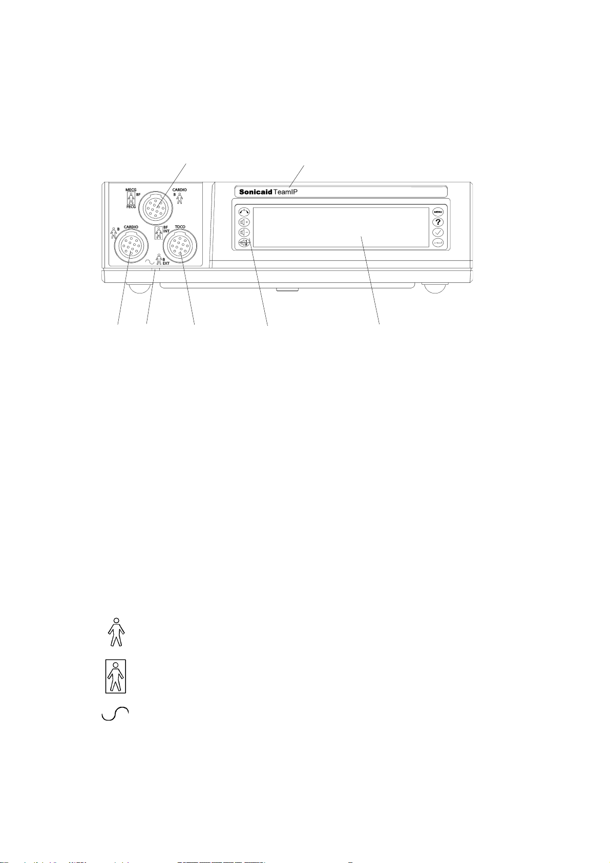
1.2 Main unit: front panel
Key
21
76543
1 CARDIO input, blue connector: 2 MHz ultrasound transducer, OR
MECG input: maternal ECG lead (optional)*, OR
FECG input for fetal ECG lead
2 Model identification: Team Standard, Team Duo, Team DM or Team IP
3 CARDIO input, yellow connector: 1.5 MHz ultrasound transducer
4 Power-on indicator light
5 EXT input, pink connector: external contractions (Toco) transducer, OR
INT input: precalibrated IUP catheter-transducer
6 Keypad, with eight control buttons
7 Display panel
* MECG is not available in the USA or Canada.
Explanation of symbols
This symbol, beside the CARDIO and EXT input sockets,
indicates that these connections are classed as Type B.
This symbol, beside the MECG*, FECG and INT TOCO input sockets,
indicates that these connections are classed as Type BF.
This symbol, by the power-on indicator light, denotes AC input.
* MECG is not available in the USA or Canada.
16
Sonicaid Team Operator’s Manual
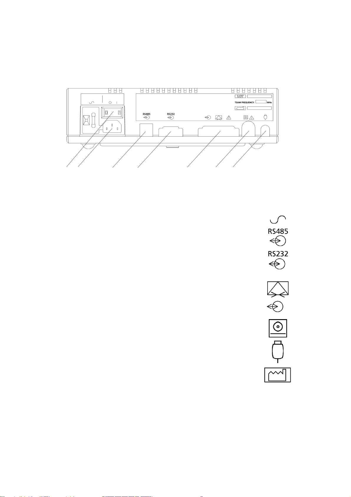
1.3 Main unit: rear panel
12 3 4 5 6 7
Key
1 AC mains on/off switch: O = off, 1 = on. When you switch
on, the power on indicator on the front panel shows green.
2 Input socket for the AC mains supply
3* RS485 Interface for Axis.(1.5kV DC isolation).
Pluggable cord connector (PCC-type).*
4* RS232 interface to a PC running Sonicaid FetalCare,
Sonicaid System8002 or a central review system
(500V DC isolation). 9-way D-type connector.*
5* Modem connection for distance monitoring. 25-way D-type.
Connect only modems which comply with EN60950.
Same connector used for the Rimkus Telemetry system.**
6* Team printer connector
8-way DIN-type.*
7* Fetal event marker socket.
1/4" stereo jack socket.*
O 1
Date of manufacture symbol.
* for details of pin connections, see Appendix 1.
** not available on Teams sold in the USA or Canada.
17
Sonicaid Team Operator’s Manual
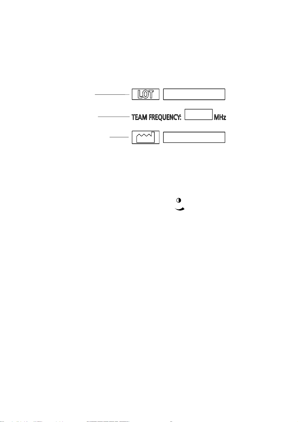
Rear panel label
The label on the rear of the Team unit shows the manufacturing serial number, the
Team frequency and the date of manufacture:
Serial number
Team frequency
Date of manufacture
1.4 Contrast control
In the base of the Team main unit is a display
contrast control, marked with this symbol
This control is for the use of service engineers only.
18
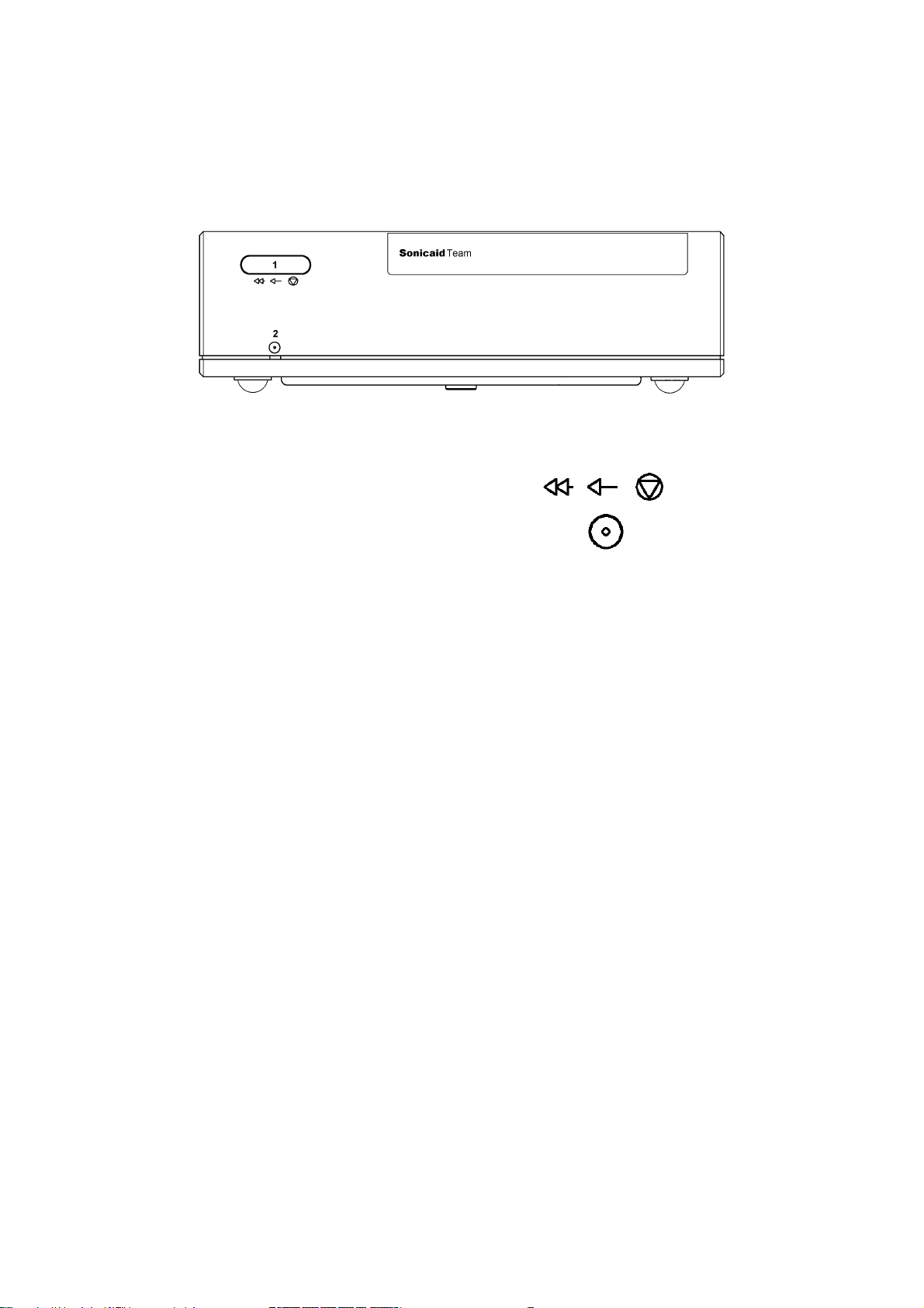
1.5 Team printer: front panel
Key
1 Printer control button. Press once for on-off.
Press and hold down for fast forward.
2 Printer on indicator.
Sonicaid Team Operator’s Manual
19
Sonicaid Team Operator’s Manual
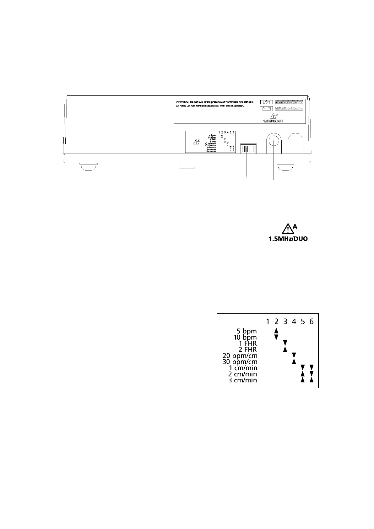
1.6 Team printer: rear panel
Key
1 Printer setting switches. See below.
1 2
2
Connector to main unit (7-pin DIN). Connect to the printer
connector on the Team main unit.
Printer switch settings
Paper speed Switch 5 Switch 6
1 cm/min Down Down
2 cm/min Up Down
3 cm/min Up Up
Scale Switch 4
20 bpm/cm Down
30 bpm/cm Up
Dual monitoring Switch 3
Side-by-side Up
Full-width Down
Graticule Switch 2
5 bpm Up
10 bpm Down
Note: switch 1 should always be Up.
Diagram on printer
20

Sonicaid Team Operator’s Manual
1.7 Team printer wedge assembly (option)
For Team fetal monitors there is a wedge which can be fitted between the Team
base unit and the Team printer unit, to improve the visibility of the trace.
To assemble
1 Remove the centre blanking-plug (if fitted) from the Team base unit top.
2 Position the printer wedge on top of the base unit, with the feet of the printer
wedge in the depressions on the rear of the base unit top.
3 Using a screwdriver, secure the screw supplied in centre hole of the wedge top
surface down into the Team base unit with approximately 4 turns.
4 Remove the printer platen. Lift the paper pack for access to the screw-head
beneath.
5 Position the pr inter unit on top of the printer wedge, with the feet of the printer
in the depressions on the printer wedge top.
6 Using a screwdriver, push down and secure the screw with approximately 4 turns.
7 Re-fit the paper pack and plat en.
To disassemble
1 Press the release button beneath the left edge of the printer platen, and lift the
platen to the left and off the top of the printer. Remove the paper pack.
2 Using a screwdriver, release the centre fixing screw (approximately 4 turns).
3 Remove the printer from the printer wedge.
4 Using a screwdriver, release the screw in the centre hole of the wedge top surface
that secures the wedge to the Team base unit.
5 Remove the printer wedge from the Team base unit.
6 Position the pr inter unit on top of the base unit, with the feet of the print er unit
in the depressions on the base unit top.
7 Using a screwdriver, push down and secure the screw with approximately 4 turns.
8 Re-fit the paper pack and plat en.
21
Sonicaid Team Operator’s Manual
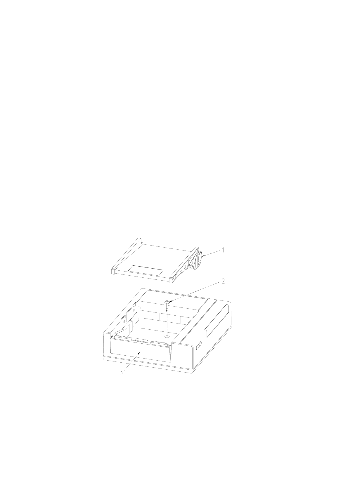
1.8 Team printer to Team base unit assembly
The Team base unit is supplied already assembled to the Team printer.
To disassemble
1 Press the release button beneath the left edge of the printer platen.
2 Lift the platen to the left and off the top of the printer.
3 Remove the paper pack.
4 Using a screwdriver, release the centre fixing screw (approximately 4 turns).
5 Remove the printer unit from the main unit.
6 Re-fit the paper pack and plat en.
To reassemble
1 Remove the centre blanking-plug (if fitted) from the Team base unit top.
2 Position the printer unit on top of the base unit. The feet of the printer unit will
locate in depressions on the base unit top.
3 Remove the platen and lift the paper pack for access to the screw-head beneath.
4 Using a screwdriver, push down and secure the screw with approximately 4 turns.
5 Re-fit the paper pack and plat en.
22
1 Printer platen shown removed
2 Centre fixing screw
3 Release button
Sonicaid Team Operator’s Manual
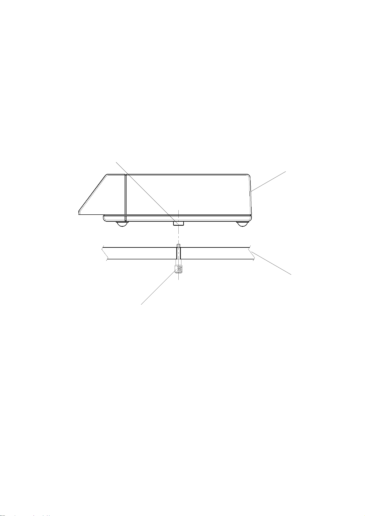
1.9 Team base unit to Team trolley assembly
A purpose-designed trolley is an option on Team.
To attach Team to the trolley:
1 Position the Team unit on the trolley top so that the securing screw is in line with
the threaded boss in the centre of the base unit.
2 Reach under the trolley top, and locate the securing screw.
3 Gently push up and secure the screw with three or four turns.
Threaded
Team unit
Securing
Trolley top
23
Sonicaid Team Operator’s Manual
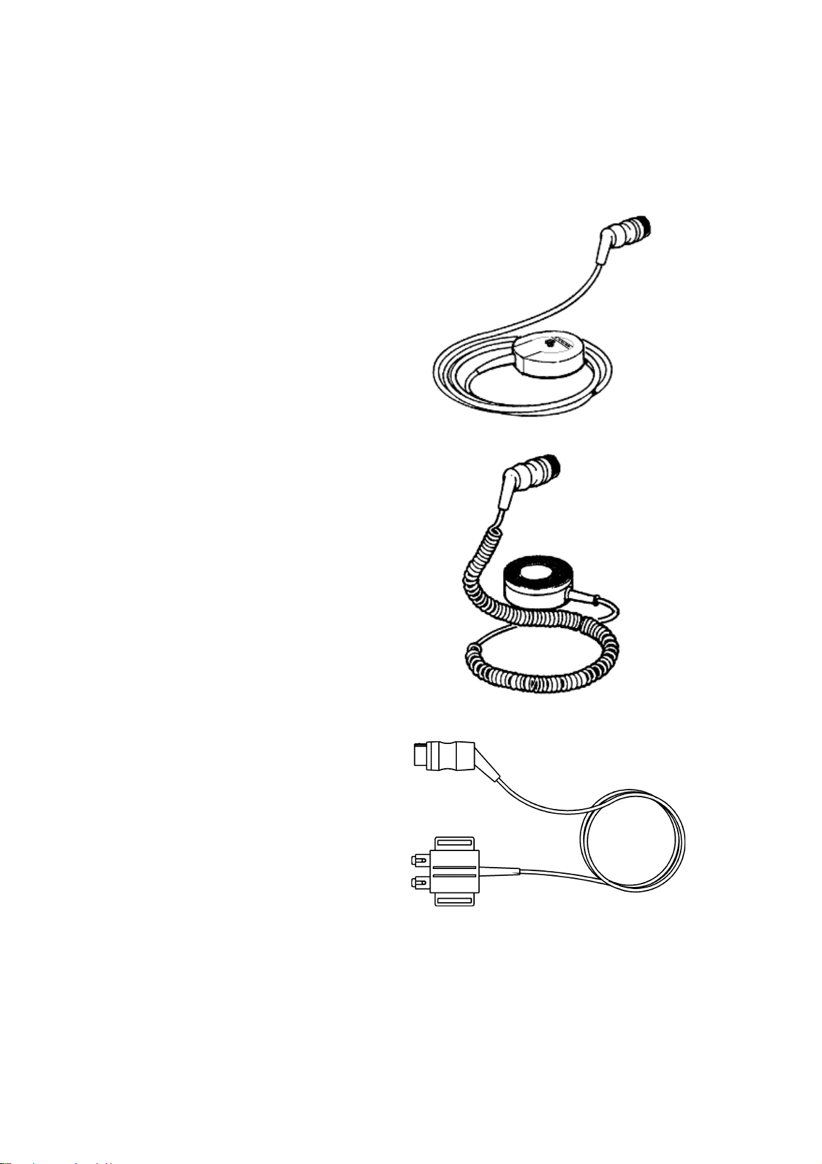
1.10 Transducers and cables
Ultrasound transducer
Used for non-invasive monitoring of
the fetal heart rate. Two transducers
are available:
Primary, yellow, 1.5MHz
Secondary, blue, 2.0MHz
The 2.0MHz transducer can only be
used on a Team Duo or Team IP base
unit.
External Toco transducer
Gives a subjective indication of
contractions pressure. Used for
non-invasive monitoring of the
timing, duration and co-ordination
of contractions.
Colour-coded pink, can be used
on all Team base units.
Sonicaid fetal ECG lead*
Strapped to the thigh of the patient,
it is used for interconnection between
Team and a fetal ECG scalp electrode.
Colour-coded blue, can only be used
on a TeamIP base unit.
* The Sonicaid fetal ECG lead is not
available in the USA or Canada.
24

Sonicaid Team Operator’s Manual
Safelinc fetal ECG lead
Attached to the mother’s leg, it is used for interconnection between Team and a
fetal ECG scalp electrode. Colour-coded blue, can only be used on a TeamIP base
unit.
Fetal movement event marker
The patient uses this hand-held pushbutton lead to record fetal movement
events.
It can be used on all Team base units.
Interconnection lead for intraut erine pressure catheter
Used for interconnection between Team and an intrauterine pressure catheter.
Colour-coded pink, can only be used on a Team IP base unit. It is not included with
the unit, but is available as an option.
Maternal ECG lead (option)*
Used for monitoring the maternal heart rate, to check that the heart rate being
recorded belongs to the fetus and not the mother. Colour-coded blue, can only be
used on a Team IP base unit. Not included with the unit, but available as an option.
* The Maternal ECG option is not available in the USA or Canada.
Transducer storage
When not in use, the ultrasound and external toco transducer can be stored by clipping
the stud on the back of the transducer into the rack on the right hand side of the Team
base unit.
25
Sonicaid Team Operator’s Manual
1.11 Team display panel
The display panel on the Team base unit has two modes for the display of monitored
information: alphanumeric display and trace display (referred to by Team as CTG).
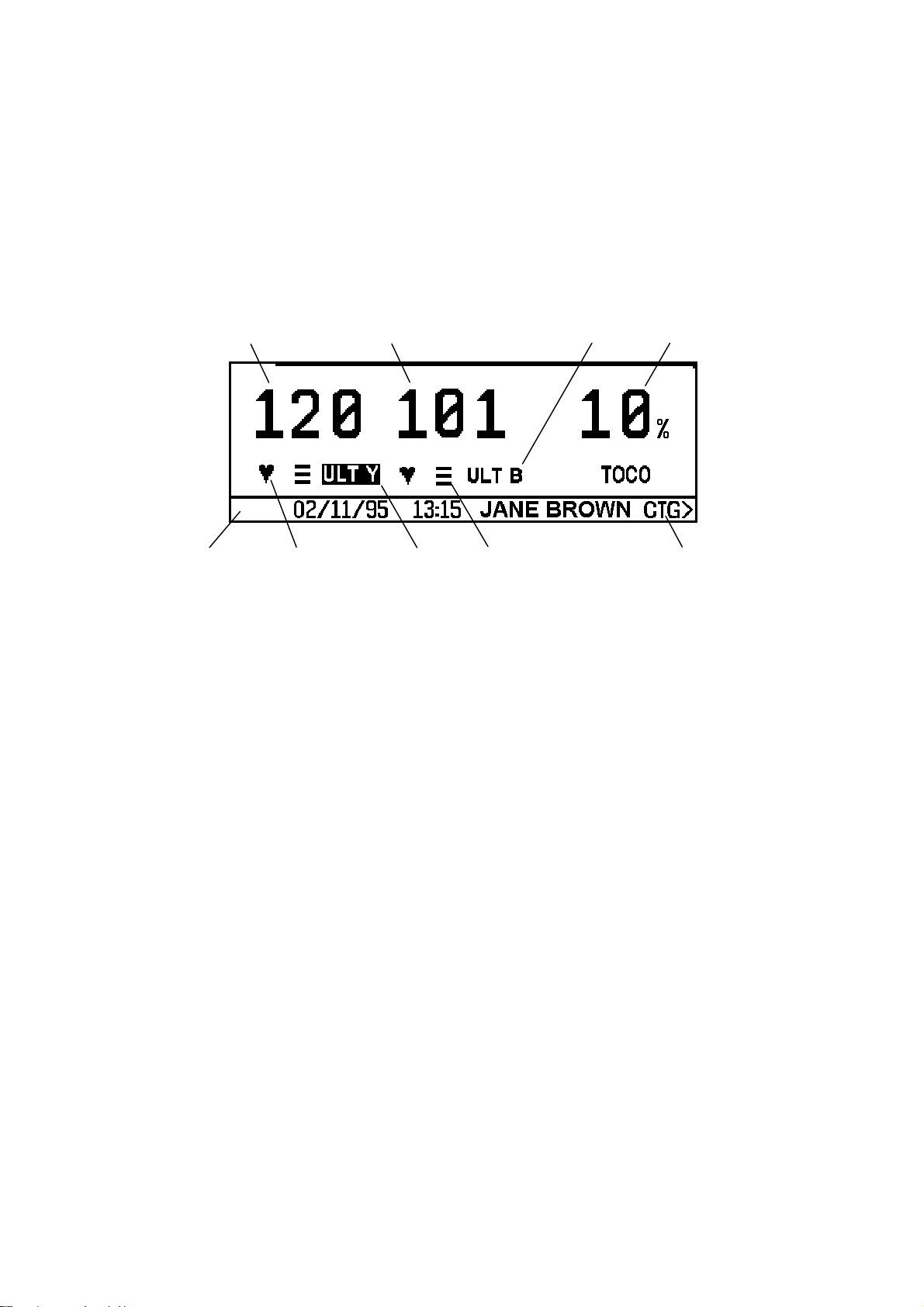
Alphanumeric display mode
11 23
45 67 8
Key to alphanumeric display
1 Heart rate, in beats per minute.
2 Channel mode, indicates source of monitored information:
ULT-Y 1.5 MHz ultrasound transducer (yellow)
ULT-B 2.0 MHz ultrasound transducer (blue)
FECG Fetal ECG scalp electrode
MECG Maternal ECG electrodes (not available in the USA or Canada)
TOCO External Toco transducer
IUP Intra-uterine pressure catheter
3 Contractions measurement:
Percentage full scale deflection, when using an external Toco transducer.
Pressure, (mmHg/kPa) when using an intrauterine pressure catheter.
4 Display Message Bar: includes date, time and patient name (if entered). Also used
for display of interactive messages.
5 Heart rate lamp: a heart-shaped flashing indicator.
6 The active audio channel: indicated by highlight on channel mode.
7 Signal quality indicator
No bars: no signal
One bar: poor
8 CTG >: press this key to change to Trace Display mode.
Note: this facility is not available on a Team IP when monitoring two heart rates
using either ULT-Y and FECG or ULT-Y and MECG.
Two bars: average
Three bars: good
26
Sonicaid Team Operator’s Manual
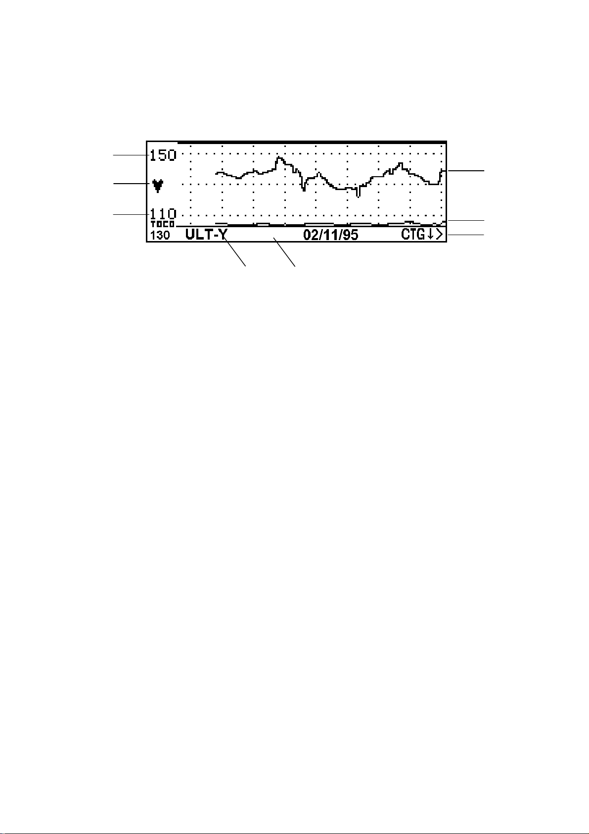
FHR Trace Display mode (CTG mode)
1
2
1
34
1 Heart rate range (beats per minute): indicates the range currently displayed.
2 Heart rate lamp: heart-shaped flashing indicator.
3 Channel mode: indicates heart rate channel on display.
4 Display message bar, used for display of interactive messages.
5
6
7
5 Heart rate trace:
Displays the active audio channel (or channel 1, yellow, if no audio is selected).
If monitoring twin heart rates, only one channel can be displayed at a time.
6 Contractions trace, compressed.
7CTG ↓ >: this menu pointer changes title and function. See below, Scr olling the
trace and returning to the alphanumeric display below.
Scrolling the trace and returning to the alphanumeric display
The fetal heart rate trace is initially displayed over the range 110-150bpm. The menu
pointer in the display message bar reads [CTG
È >].
To scroll the display vertically:
1 Press the Enter button next to the menu pointer.
The display will show the trace over the range 80-120bpm.
The menu pointer will then read [CTG
Ç >].
2 Press the Enter button next to the menu pointer.
The display will show the trace over the range 140-180bpm.
The menu pointer will then read [ALPHA >].
3 Press the Enter button next to the menu pointer.
The display will return to Alphanumeric display mode.
To scroll the display horizontically, press the Clinical Event marker button [9].
27

Sonicaid Team Operator’s Manual
1.12 The Team Keypad
1
2
3
4
There are eight buttons on the Team display panel. Their primary functions are:
1 Toco zero: zeroes the external Toco (contractions) transducer or IUP catheter.
2 Volume control up
3 Volume control down
4 Channel select
5 Menu access
6 Display Help page
7 Clinical event marker
8 Enter: confirms an entry or switches display modes
5
6
7
8
28

Sonicaid Team Operator’s Manual
2 Getting Started
2.1 Summary of recording procedure
Setup
1 Place transducer belts across the bed or chair.
2 Make the patient comfortable in a semi-recumbent or sitting position.
Preparing the Team
1 Switch on. The on/off sw itch is on the rear of the base unit.
2 Check paper. Is there sufficient paper for the monitoring session? Make sure the
printer platen is securely closed.
3 Connect transducers. The plugs and sockets are colour-coded; the display confirms
transducer connection.
Transducer placement
1 Palpate the abdomen to determine fetal lie and position.
2 Position the Toco t ransducer (pink) centrally, halfway between fundus and
umbilicus. Do not use gel. Secure with belt and buckle.
3 Zero the Toco. Make sure the uterus is relaxed, then press the Toco zero button.
The 10% baseline is displayed.
4 Gel the ultrasound transducer (yellow). Place it on the abdomen so as to obtain a
clear heart sound. Secure with belt and buckle.
5 Check that the fetal heart rate is clear, and distinct from the maternal pulse rate
taken at the mother’s wrist. Note the maternal pulse rate on the chart paper.
Optimum signal quality for the fetal heart rate is shown by 3 bars on the display,
with a flashing heart at each beat.
6 Adjust t he volume using the volume up and down keys.
7 Connect the fetal event marker to the socket on the rear panel. Show the patient
how to use it.
29

Sonicaid Team Operator’s Manual
Using the printer
1 To swit ch the printer on, press the button on the printer front panel.
2 To fas t forward the paper, press and hold down the printer button.
3 To stop the printer, press the printer button again.
Using the second ultrasound tr ansducer for twins
1 Connect the second ultrasound transducer (blue) to the Team. The display
switches to twin heart rate display.
2 Place both ultrasound transducers on the patient’s abdomen in the optimum
position. Use the blue ultrasound transducer to monitor the first, presenting twin.
3 Make sure each fetal heart rate is from a separate fetus. See Section 3.4. If in doubt,
ask for assistance. Secure the ultrasound transducers with belts and buckles.
4 To select Audio, press the bottom left button on the keypad. The active audio
channel is highlighted on the display.
Monitoring fetal ECG
Using a Sonicaid scalp electrode:
1 Put electrode gel on the base of the leg plate, then strap the leg plate to the
patient’s thigh. Secure with the belt.
2 Connect the FECG lead to the Team.
3 Once the membranes are ruptured, attach the electrode to the fetus as described
in the electrode instructions.
4 Connect the electrode leads to the leg plate. Make sure a good signal is
maintained.
5 Wait for the signal to stabilize and a clear fetal heart rate to be displayed on the
Team base unit display. Then adjust the volume control.
Using a Safelinc electrode:
1 Attach the FECG lead to the mother’s leg.
2 Once the membranes are ruptured, attach the FECG electrode to the fetal pre-
senting part.
3 Connext the FECG electrode to the FECG lead.
4 Wait for the signal to stabilize and a clear fetal heart rate to be displayed on the
Team base unit display. Then adjust the volume control.
See also Section 3.3.
30
 Loading...