

Huntleigh Healthcare Dopplex Service Manual
Huntleigh Healthcare Ltd - A Huntleigh Technology PLC company. Dopplex® ,
Huntleigh and 'H' logo are registered trademarks of Huntleigh Technology PLC
2003.
© Huntleigh Healthcare Ltd. 2003
Service Agreements
Periodic inspection and preventative maintenance are essential to ensure
continued effective operation. Contact the Company or its approved agents or
distributors for further information on service contracts.
HEALTHCARE
SERVICE MANUAL
Dopplex®
Fetal Assist
SERVICE MANUAL
Dopplex®
Fetal Assist

2
Table of Contents
HEALTHCAR
E
1.
General Information . . . . . . . . . . . . . . . . . . . . . . . . . . . . . . . . .5
Contents Page No.
2.1 General Safety . . . . . . . . . . . . . . . . . . . . . . . . . . . . . . . . . . . . . . . . . . . . . . .9
2.2 Safety Testing . . . . . . . . . . . . . . . . . . . . . . . . . . . . . . . . . . . . . . . . . . . . . . . .10
2.3 Power Adaptor . . . . . . . . . . . . . . . . . . . . . . . . . . . . . . . . . . . . . . . . . . . . . . .10
2.4 Assist Host and Docking Station . . . . . . . . . . . . . . . . . . . . . . . . . . . . . . . . . .10
2.5 Cleaning . . . . . . . . . . . . . . . . . . . . . . . . . . . . . . . . . . . . . . . . . . . . . . . . . . . .11
2.6 Preventative Maintenance . . . . . . . . . . . . . . . . . . . . . . . . . . . . . . . . . . . . . . .11
2.7 CE Marking . . . . . . . . . . . . . . . . . . . . . . . . . . . . . . . . . . . . . . . . . . . . . . . . .11
Quality, Reliability and Safety . . . . . . . . . . . . . . . . . . . . . . . . . .9
2.
3.1 EN60601-1 Classification . . . . . . . . . . . . . . . . . . . . . . . . . . . . . . . . . . . . . . .12
3.2 General . . . . . . . . . . . . . . . . . . . . . . . . . . . . . . . . . . . . . . . . . . . . . . . . . . . .12
3.3 Environmental . . . . . . . . . . . . . . . . . . . . . . . . . . . . . . . . . . . . . . . . . . . . . . . .12
3.4 Physical . . . . . . . . . . . . . . . . . . . . . . . . . . . . . . . . . . . . . . . . . . . . . . . . . . . .12
Specifications . . . . . . . . . . . . . . . . . . . . . . . . . . . . . . . . . . . . . .12
3.
5.1 Introduction . . . . . . . . . . . . . . . . . . . . . . . . . . . . . . . . . . . . . . . . . . . . . . . . .14
5.2 Overview of Circuit Functionality . . . . . . . . . . . . . . . . . . . . . . . . . . . . . . . . . .14
5.3 The AMD SC400 Micro Controller . . . . . . . . . . . . . . . . . . . . . . . . . . . . . . . . .14
5.4 CPU Clocks . . . . . . . . . . . . . . . . . . . . . . . . . . . . . . . . . . . . . . . . . . . . . . . . .14
5.5 ROM / FLASH Interface . . . . . . . . . . . . . . . . . . . . . . . . . . . . . . . . . . . . . . . . .14
5.6 DRAM Controller . . . . . . . . . . . . . . . . . . . . . . . . . . . . . . . . . . . . . . . . . . . . . .15
5.7 SC400 Functions Used by the PMA Main PCB . . . . . . . . . . . . . . . . . . . . . . . .15
5.7.1 PC Card Socket 1 (PCMCIA Port) . . . . . . . . . . . . . . . . . . . . . . . . . . . . . . . . .16
5.8 Flash Memory . . . . . . . . . . . . . . . . . . . . . . . . . . . . . . . . . . . . . . . . . . . . . . .16
5.9 Battery Level Comparator . . . . . . . . . . . . . . . . . . . . . . . . . . . . . . . . . . . . . . .16
5.10 On/Off Detect CIrcuit . . . . . . . . . . . . . . . . . . . . . . . . . . . . . . . . . . . . . . . . . . .16
5.11 Clock Ladder . . . . . . . . . . . . . . . . . . . . . . . . . . . . . . . . . . . . . . . . . . . . . . . .17
5.12 Docking Power and Detect Circuit . . . . . . . . . . . . . . . . . . . . . . . . . . . . . . . . .17
5.13 VR Micro Controller . . . . . . . . . . . . . . . . . . . . . . . . . . . . . . . . . . . . . . . . . . . .17
5.14 Dual Port RAM Interface . . . . . . . . . . . . . . . . . . . . . . . . . . . . . . . . . . . . . . . .18
5.15 Ultra I/O . . . . . . . . . . . . . . . . . . . . . . . . . . . . . . . . . . . . . . . . . . . . . . . . . . . .18
5.16 Parallel Port . . . . . . . . . . . . . . . . . . . . . . . . . . . . . . . . . . . . . . . . . . . . . . . . .18
5.17 Serial Port . . . . . . . . . . . . . . . . . . . . . . . . . . . . . . . . . . . . . . . . . . . . . . . . . . .19
5.18 32KHz Oscillator . . . . . . . . . . . . . . . . . . . . . . . . . . . . . . . . . . . . . . . . . . . . . .19
5.19 RESET and Watchdog Circuit . . . . . . . . . . . . . . . . . . . . . . . . . . . . . . . . . . . .19
5.20 Graphics Controller . . . . . . . . . . . . . . . . . . . . . . . . . . . . . . . . . . . . . . . . . . . .20
5.21 Memory Addressing . . . . . . . . . . . . . . . . . . . . . . . . . . . . . . . . . . . . . . . . . . .20
5.22 Contrast and Brightness Control . . . . . . . . . . . . . . . . . . . . . . . . . . . . . . . . . .20
5.23 Touch Screen Control . . . . . . . . . . . . . . . . . . . . . . . . . . . . . . . . . . . . . . . . . .21
5.24 Key Pad Interface . . . . . . . . . . . . . . . . . . . . . . . . . . . . . . . . . . . . . . . . . . . . .21
5.25 Touch Screen Controller . . . . . . . . . . . . . . . . . . . . . . . . . . . . . . . . . . . . . . . .21
Main PCB Circuit Description . . . . . . . . . . . . . . . . . . . . . . . . . .14
5.
4.1 The Doppler Principle . . . . . . . . . . . . . . . . . . . . . . . . . . . . . . . . . . . . . . . . . .13
4.2 Doppler Audio Processing . . . . . . . . . . . . . . . . . . . . . . . . . . . . . . . . . . . . . . .13
Technical Classification . . . . . . . . . . . . . . . . . . . . . . . . . . . . . .13
4.
1.1 Introduction . . . . . . . . . . . . . . . . . . . . . . . . . . . . . . . . . . . . . . . . . . . . . . . . .5
1.2 System Components . . . . . . . . . . . . . . . . . . . . . . . . . . . . . . . . . . . . . . . . . .5
1.3 Servicing Policy . . . . . . . . . . . . . . . . . . . . . . . . . . . . . . . . . . . . . . . . . . . . . . .6
1.4 Acoustic Safety . . . . . . . . . . . . . . . . . . . . . . . . . . . . . . . . . . . . . . . . . . . . . . .7
1.5 Product Description . . . . . . . . . . . . . . . . . . . . . . . . . . . . . . . . . . . . . . . . . . . .7
1.6 Antistatic Handling, Electro Static Discharge (ESD) . . . . . . . . . . . . . . . . . . . . .7
1.7 Construction . . . . . . . . . . . . . . . . . . . . . . . . . . . . . . . . . . . . . . . . . . . . . . . . .8

3
Table of Contents
HEALTHCAR
E
6.1 Microcontroller Section . . . . . . . . . . . . . . . . . . . . . . . . . . . . . . . . . . . . . . . . .22
6.1.1 3048 Microcontroller . . . . . . . . . . . . . . . . . . . . . . . . . . . . . . . . . . . . . . . . . . .22
6.1.2 Watchdog . . . . . . . . . . . . . . . . . . . . . . . . . . . . . . . . . . . . . . . . . . . . . . . . . .25
6.1.3 H8/3048 H Resource Assignments . . . . . . . . . . . . . . . . . . . . . . . . . . . . . . . .25
6.1.4 On-chip Flash Programming Voltage . . . . . . . . . . . . . . . . . . . . . . . . . . . . . . .25
6.2 Power Supply . . . . . . . . . . . . . . . . . . . . . . . . . . . . . . . . . . . . . . . . . . . . . . . .25
6.2.1 Switching regulator . . . . . . . . . . . . . . . . . . . . . . . . . . . . . . . . . . . . . . . . . . . .25
6.2.2 ± 10V linear regulator . . . . . . . . . . . . . . . . . . . . . . . . . . . . . . . . . . . . . . . . . .26
6.2.3 5V_ANA supply . . . . . . . . . . . . . . . . . . . . . . . . . . . . . . . . . . . . . . . . . . . . . . .26
6.2.4 Transducer power switching . . . . . . . . . . . . . . . . . . . . . . . . . . . . . . . . . . . . .26
6.3 Signal processing . . . . . . . . . . . . . . . . . . . . . . . . . . . . . . . . . . . . . . . . . . . . .26
6.3.1 Input multiplexing . . . . . . . . . . . . . . . . . . . . . . . . . . . . . . . . . . . . . . . . . . . . .26
6.3.2 Ultrasound low pass filters . . . . . . . . . . . . . . . . . . . . . . . . . . . . . . . . . . . . . . .26
6.3.3 FMD bandpass filter . . . . . . . . . . . . . . . . . . . . . . . . . . . . . . . . . . . . . . . . . . .27
6.3.4 High pass filter . . . . . . . . . . . . . . . . . . . . . . . . . . . . . . . . . . . . . . . . . . . . . . .27
6.3.5 Audio Amplifier / limiter . . . . . . . . . . . . . . . . . . . . . . . . . . . . . . . . . . . . . . . . .27
6.3.6 Anti-alias filter . . . . . . . . . . . . . . . . . . . . . . . . . . . . . . . . . . . . . . . . . . . . . . . .27
6.3.7 Digital Gain control . . . . . . . . . . . . . . . . . . . . . . . . . . . . . . . . . . . . . . . . . . . .27
6.3.8 AGC Raw . . . . . . . . . . . . . . . . . . . . . . . . . . . . . . . . . . . . . . . . . . . . . . . . . . .28
6.3.9 Ultrasound oscillator / timing . . . . . . . . . . . . . . . . . . . . . . . . . . . . . . . . . . . . .28
6.3.10 ESD Protection . . . . . . . . . . . . . . . . . . . . . . . . . . . . . . . . . . . . . . . . . . . . . . .28
Fetal Assist Overview . . . . . . . . . . . . . . . . . . . . . . . . . . . . . . . .22
6.
Contents Page No.
Transducers and Accessories . . . . . . . . . . . . . . . . . . . . . . . . . .29
7.
7.1 Ultrasound Transducer - US1 . . . . . . . . . . . . . . . . . . . . . . . . . . . . . . . . . . . .29
7.1.1 Ultrasound Transducer Functional Block Diagram . . . . . . . . . . . . . . . . . . . . .29
7.1.2 Ultrasound Transducer Key Parameters . . . . . . . . . . . . . . . . . . . . . . . . . . . . .29
7.1.3 Ultrasound Transducer Construction . . . . . . . . . . . . . . . . . . . . . . . . . . . . . . .30
7.1.4 Ultrasound Transducer Connector . . . . . . . . . . . . . . . . . . . . . . . . . . . . . . . . .30
7.2 Toco Transducer - CT1 . . . . . . . . . . . . . . . . . . . . . . . . . . . . . . . . . . . . . . . . .31
7.2.1 Toco Functional Block Diagram . . . . . . . . . . . . . . . . . . . . . . . . . . . . . . . . . . .31
7.2.2 Toco Construction . . . . . . . . . . . . . . . . . . . . . . . . . . . . . . . . . . . . . . . . . . . . .31
7.2.3 Toco Connector . . . . . . . . . . . . . . . . . . . . . . . . . . . . . . . . . . . . . . . . . . . . . .31
Mains Adaptor / Battery Pack Specification . . . . . . . . . . . . . . .35
9.
9.1 Mains Adaptor . . . . . . . . . . . . . . . . . . . . . . . . . . . . . . . . . . . . . . . . . . . . . . .35
9.1.1 Introduction . . . . . . . . . . . . . . . . . . . . . . . . . . . . . . . . . . . . . . . . . . . . . . . . .35
9.1.2 Mains Input . . . . . . . . . . . . . . . . . . . . . . . . . . . . . . . . . . . . . . . . . . . . . . . . .35
9.1.3 DC Output . . . . . . . . . . . . . . . . . . . . . . . . . . . . . . . . . . . . . . . . . . . . . . . . . .35
9.1.4 Safety Isolation . . . . . . . . . . . . . . . . . . . . . . . . . . . . . . . . . . . . . . . . . . . . . . .35
9.1.5 Operating Environment . . . . . . . . . . . . . . . . . . . . . . . . . . . . . . . . . . . . . . . . .35
9.1.6 Storage Environment . . . . . . . . . . . . . . . . . . . . . . . . . . . . . . . . . . . . . . . . . .36
9.1.7 Electromagnetic Compatibility . . . . . . . . . . . . . . . . . . . . . . . . . . . . . . . . . . . .36
9.2 Battery Pack . . . . . . . . . . . . . . . . . . . . . . . . . . . . . . . . . . . . . . . . . . . . . . . . .36
9.2.1 Introduction . . . . . . . . . . . . . . . . . . . . . . . . . . . . . . . . . . . . . . . . . . . . . . . . .36
9.2.2 Cell Type . . . . . . . . . . . . . . . . . . . . . . . . . . . . . . . . . . . . . . . . . . . . . . . . . . .37
9.2.3 Battery Discharge . . . . . . . . . . . . . . . . . . . . . . . . . . . . . . . . . . . . . . . . . . . . .37
9.2.4 Desktop Operation - Power fed through the Battery Pack . . . . . . . . . . . . . . . .37
8.1 Desktop Operation - Power fed through the Docking Station . . . . . . . . . . . . .33
8.2 Docking Station Block Diagram . . . . . . . . . . . . . . . . . . . . . . . . . . . . . . . . . . .34
Docking Station . . . . . . . . . . . . . . . . . . . . . . . . . . . . . . . . . . . .33
8.

4
Table of Contents
HEALTHCAR
E
Contents Page No.
16.1 Soak Test . . . . . . . . . . . . . . . . . . . . . . . . . . . . . . . . . . . . . . . . . . . . . . . . . . .69
16.2 Post Soak Procedure . . . . . . . . . . . . . . . . . . . . . . . . . . . . . . . . . . . . . . . . . .69
Modular Diagrams . . . . . . . . . . . . . . . . . . . . . . . . . . . . . . . . . .48
16.
11.1 Unit Dismantling . . . . . . . . . . . . . . . . . . . . . . . . . . . . . . . . . . . . . . . . . . . . . .39
11.2 Removal of Host PCB . . . . . . . . . . . . . . . . . . . . . . . . . . . . . . . . . . . . . . . . . .39
11.3 Removal of Touch Screen & LCD Module . . . . . . . . . . . . . . . . . . . . . . . . . . .40
11.4 Invertor PCB Removal . . . . . . . . . . . . . . . . . . . . . . . . . . . . . . . . . . . . . . . . . .40
11.5 Speaker Removal . . . . . . . . . . . . . . . . . . . . . . . . . . . . . . . . . . . . . . . . . . . . .40
11.6 Removal of the Keypad . . . . . . . . . . . . . . . . . . . . . . . . . . . . . . . . . . . . . . . . .40
11.7 Fetal Module . . . . . . . . . . . . . . . . . . . . . . . . . . . . . . . . . . . . . . . . . . . . . . . .40
11.8 ACT3/AUS3 (Ultrasound) Transducer Dismantling . . . . . . . . . . . . . . . . . . . . . .41
11.9 Re-assembly of ACT3/AUS3 (Ultrasound) Transducer . . . . . . . . . . . . . . . . . .41
11.10 Strain Gauge Assembly Removal . . . . . . . . . . . . . . . . . . . . . . . . . . . . . . . . .41
11.11 Strain Gauge Assembly Refitting . . . . . . . . . . . . . . . . . . . . . . . . . . . . . . . . . .41
11.12 ACT3 Transducer Alignment . . . . . . . . . . . . . . . . . . . . . . . . . . . . . . . . . . . . .41
11.13 Replacing the Transducer Cable . . . . . . . . . . . . . . . . . . . . . . . . . . . . . . . . . .43
Electrostatic Discharge (ESD) Precautions . . . . . . . . . . . . . . . .38
10.
Servicing Procedures . . . . . . . . . . . . . . . . . . . . . . . . . . . . . . . .39
11.
12.
13.
14.
15.
10.1 What is Static Electricity? . . . . . . . . . . . . . . . . . . . . . . . . . . . . . . . . . . . . . . . .38
Ordering Spare Parts . . . . . . . . . . . . . . . . . . . . . . . . . . . . . . . .44
Fault Finding . . . . . . . . . . . . . . . . . . . . . . . . . . . . . . . . . . . . . . .45
Transducer / Cable Assemblies . . . . . . . . . . . . . . . . . . . . . . . .57
Fetal Functional Inspection & Test Procedure . . . . . . . . . . . . . .69
18.
Warranty and Service . . . . . . . . . . . . . . . . . . . . . . . . . . . . . . . .76
17.
Field Software Upgrades for Fetal Assist . . . . . . . . . . . . . . . . .75
15.1 AUS Ultrasound Transducer Assembly . . . . . . . . . . . . . . . . . . . . . . . . . . . . .57
15.2 ACT3 Transducer Assembly . . . . . . . . . . . . . . . . . . . . . . . . . . . . . . . . . . . . .60
15.3 AEM3 Event Marker Transducer Assembly . . . . . . . . . . . . . . . . . . . . . . . . . .68
Althhoughh everyy care hhas been takken to ensure thhat thhe information in thhis manual is accurate,
continuous development mayy result in equipment chhanges.. TThhe Companyy reserves thhe righht to
makke suchh chhanges wwithhout prior notification, and resulting manual inaccuracies mayy occur.. TThhis
manual and anyy chhanges are protected byy copyyrighht..
5
Product Description
HEALTHCAR
E
The
Dopplex® Assist
range of modular
medical systems is a new generation of
medical devices designed to meet the
demands of healthcare providers worldwide.
This service manual provides the technical
information required for repair and
maintenance of the Huntleigh Healthcare Fetal
Assist.
Using it’s modular approach, the
Dopplex®
Fetal Assist
provides the user with a compact,
flexible, functional solution. System flexibility
allows the user to connect application specific
modules to the host.
1. General Information
1.1 Introduction
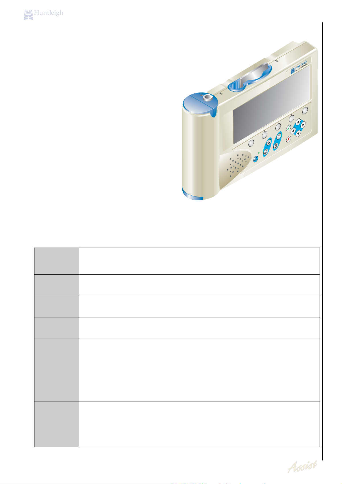
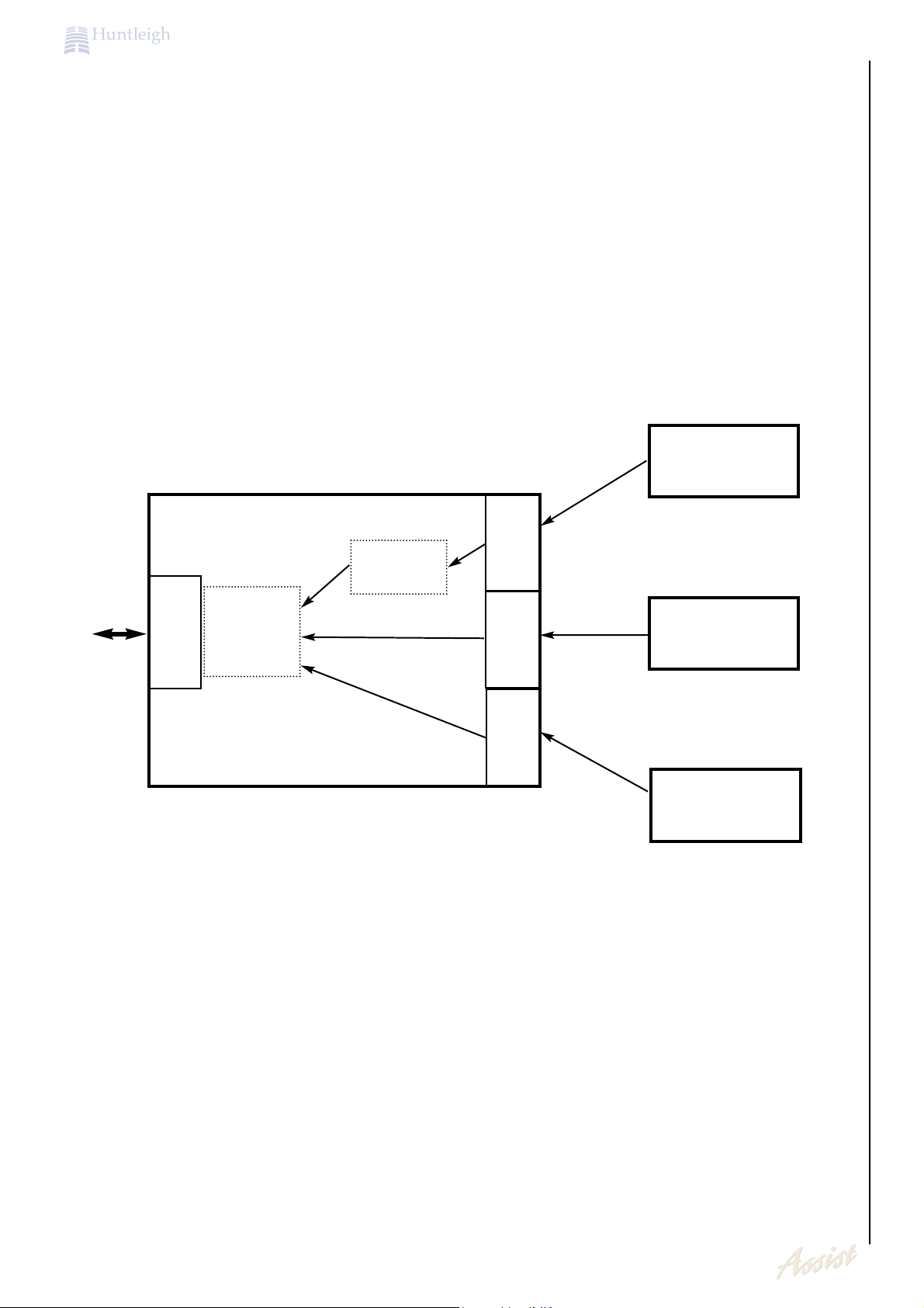
The Dopplex Assist is modular in format, requiring that several components are assembled
before a particular procedure can be undertaken.
1.2 System Components
This is a rectangular ‘box’, (approx. 180* 140* 20mm), which contains all the
necessary electronics and software to perform the specified function.
Application
Module
The batteries are housed in a unit that fits into the Host. The design of the case
is such that the Battery Pack can only be inserted in one way.
Battery Pack
This unit allows the Host/Module combination to be powered from mains
electricity supply. The batteries can also be recharged from the output of this
unit, during, or independent of, patient assessments.
The output is regulated, and the complete power adaptor meets the safety
requirements of EN60601-1.
The output of the power adaptor is fitted with a unique connector that is specific
for use with the Dopplex Assist system.
Power
Adaptor
Host Unit
Patient
Applied Parts
(Transducers)
These items produce the signals that are analysed by the Dopplex Assist
system. They plug into the Module via 9 pin connectors.
This is a handheld core system powered from rechargeable batteries, or via a
mains adaptor. It includes a graphic display and connectivity and data
storage/management.
This accessory allows the Host/Module combination, (together with the battery
pack), to be used as a desktop unit. The unit is held at a convenient angle for
viewing the displayed results.
The preferred option is for the power adaptor to be connected to the Docking
Station. In this configuration, an external printer and audio speakers are available.
Docking
Station
6
Product Description
HEALTHCAR
E
To reduce the risk of electric shock, do not remove the cover or back. Refer servicing to
qualified service personnel.
Only trained service technicians should perform all unit repairs.
Voltages dangerous to life exist in this unit. Take care when servicing the power supply and
display assembly.
Due to the nature of static-sensitive surface-mount technology, specialised equipment and
training is required when working on the surface mounted components used within this
product.
For this reason, circuit diagrams are not included in this manual. Block diagrams and fault
finding sections are included to make fault finding to modular or leaded component level
possible.
Units within the warranty period must not be dismantled and should be returned to Huntleigh
Healthcare, Diagnostic Products Division for repair. Any units returned showing signs of
tampering or accidental damage will not be covered under the warranty.
Caution!
1.3 Servicing Policy
Several elements are brought together in this unit. They are described below:
Host Unit
Can be used to input information in addition to using
the Touch Screen.
Location
Element
Function
A headphone socket is provided for the clinician to
listen to procedures if required. A mono loudspeaker
is also included for audio presentations.
A serial input/output port for connection to an external
keyboard or mouse is also provided.
Displays information useful to the clinician such as
patient information, results of procedures etc.
Right Hand Edge
Front Face
Front Face
Touch Screen
Membrane
Keypad
Headphone and
Serial Port Sockets
This permits connection from an external
telephone/LAN network to be made to the Dopplex
Assist so that information gathered can be
downloaded to a central location. The Fax/modem
cards are manufactured to comply with EN60950.
Top Edge
PCMCIA Port
For the indirect entry of patient data.
Right Hand Edge
Provides wireless printing capability
Smart Card Reader
Right Hand Edge
IrDA Port

7
Product Description
HEALTHCAR
E
1.4 Acoustic Safety
Continuous wave Doppler ultrasound instruments such as the ASSIST have been used
extensively for medical diagnosis in the United States for over 25 years. Throughout this period,
there have been no reports of adverse effects to patients or instrument operators at the
acoustic intensities recommended for diagnostic use. Despite this highly favourable safety
experience, available data is not conclusive and the possibility remains that unwanted biological
effects might be identified in the future.
Authorities therefore recommend that ultrasound procedures be performed in accordance with
the "ALARA" principle, which states that the energy delivered to the patient should always be
kept As Low As Reasonably Achievable. With the ASSIST RANGE, the transmitted acoustic
power is fixed and cannot be adjusted by the operator. Therefore, the user can best observe
the ALARA principle by ensuring that each examination is medically indicated and by limiting
the duration of the study to the extent appropriate for the clinical objectives.
The Dopplex Assist range of modular systems is designed to fulfil a multitude of application
areas using a single 'host' unit and selecting the relevant module to provide the required
functionality.
The host unit comprises
High resolution ½ VGA colour graphic display complete with touch screen for data entry
Internal rechargeable battery providing up to 4 hours use
Internal memory for storage of patient record
PCMCIA slot for expansion of memory or addition of modem/network card
Smartcard reader allowing direct patient data entry
1.5 Product Description
By fitting the fetal module, the Assist becomes a handheld obstetric assessment unit
incorporating full fetal monitoring (CTG) capability, utilising a selection of transducers.
The
Fetal Assist
can also be connected to a colour printer to allow high quality printouts of the
fetal test.
Fetal Module
1.6 Antistatic Handling, Electro Static Discharge (ESD)
The
Fetal Assist
range uses Electrostatic Discharge Sensitive Devices (ESD's) in its
manufacture. The damage they suffer when handled incorrectly may be catastrophic.
More often and potentially even worse, the damage may be partial or latent, seriously impairing
the reliability of the unit.
Due to the nature of the components used within the Assist, special precautions must be taken
to avoid damage to the circuitry. Static damage may not be immediately evident but could
cause premature failure.
The Assist must only be dismantled and serviced within an ESD protected area (EPA) as
defined by CECC00015 (published by CENELEC) to avoid damage to the assemblies.

HEALTHCAR
E
8
Product Description
1.7 Construction
The Host unit comprises five PCB's, the main PCB, docking station connector, Smartcard
reader, bulkhead and LCD backlight PCB's.
The fetal module consists of one main PCB.
All electromechanical and through hole components are serviceable using standard tools and
soldering techniques, provided that anti-static precautions are always taken.
Recommended servicing is limited to replacement of assemblies detailed in this manual.

9
Quality Reliability and Safety
HEALTHCAR
E
TThhis equipment hhas been manufactured using qualityy components and designed to operate
safelyy and wwithh reliabilityy.. Huntleighh Healthhcare Limited can accept responsibilityy onlyy if thhe
followwing conditions are observed..
TThhe equipment is used in accordance wwithh thhe instructions for use provided byy Huntleighh
Healthhcare..
TThhe equipment is used in a building wwhhose electrical installations conform to thhe standards
specified byy thhe countryy in wwhhichh thhe building is situated..
If thhe integrityy of thhe protective earthh conductor arrangement is in doubt, thhe equipment shhould
be operated from its internal electrical powwer source..
All modifications and repairs to thhe equipment are carried out byy service engineers, agents or
hhospital techhnicians authhorised byy Huntleighh Healthhcare Limited..
TThhe Fetal Assist and its transducers are designed to hhighh standards of performance, reliabilityy
and safetyy..
Functional and safetyy chheckks shhould alwwayys be made after carryying out anyy repairs or
dismantling thhe equipment..
It is recommended thhat regular inspections are to be made to chheckk thhe integrityy of thhe unit,
and to ensure cables are not shhowwing anyy signs of wwear or noise wwhhen flexed..
A possible explosion hazard exists if used in the presence of flammable
anaesthetics. Explosion or fire can result.
Possible Fire
or Explosion
Do not
immerse any portion of the instrument in water. Fluid spills may
damage the instrument's electrical components.
Do not
sterilise this product. Sterilisation environments can cause severe
damage.
Do not
autoclave or gas sterilise accessories unless manufacturer instructions
clearly approve it.
Possible
Equipment
Damage
Do not
substitute accessories. Use only recommended accessories listed in
this manual. Substitution may cause the instrument to work improperly. The
correct accessories are shielded to prevent conductive parts of the electrodes
contacting other conductive parts or earth.
Possible
Safety Risk
The following are descriptions of general hazards and unsafe practices that
could result in death, severe injury or product damage. Specific warnings and
cautions not appearing in this section are found throughout the manual.
Note
2. Quality Reliability and Safety
Possible
Electrical
Hazard
Do not
operate the equipment using damaged cables and wires, or loose snap
fittings, which may cause interference or loss of signal.
Do
perform frequent electrical and visual inspections on cables and wires.
2.1 General Safety

10
Quality Reliability and Safety
HEALTHCAR
E
Do not
use this equipment in the presence of flammable gases.
Do not
immerse any part of the equipment in any liquids.
Do not
use solvent cleaner on any part of the system.
Do not
use high temperature sterilising or E-beam / gamma sterilisation processes.
This product contains sensitive electronics; strong radio frequency fields could interfere
with the operation of the system. In the event where this occurs, we suggest that the
source of interference is identified and the equipment is used 'out of range'.
If anyy doubt exists concerning thhe use of thhis equipment, an alternative methhod shhould be
used..
2.2 Safety Testing
Using suitable safety test equipment, refer to the following guidelines;
2.3 Power Adaptor
Maximum allowable leakage current : 100 µA Limit
Enclosure Leakage Current : 100 µA Limit
Earth Leakage Test
Apply 1500Vac to the mains connector, connecting the low voltage probe to the "EARTH"
terminal. Firstly test the "LIVE" terminal and then the "NEUTRAL" for 60 seconds each. No
breakdowns should occur.
The output from the power adaptor is double insulated from its supply. The third pin from the
adaptor is earthed but this is a functional earth and not a safety earth.
Breakdown Test
2.4 Assist Host and Docking Station
Due to the fact that these are powered from an isolated supply, testing of these units is not
necessary.
If you require any assistance with safety testing your Huntleigh Diagnostics equipment, contact
Huntleigh Diagnostics. For the UK refer to the Health Equipment Information Document No 95 Code Of Practice or IEC 601 Standards For Acceptance Testing Of Medical Equipment.
The following safety summary should be read before operating or carrying out any of the
procedures described in this manual:
Mains to Case : > 200 M
Insulation Test
Patient Leakage : <10 µA DC
<100 µA AC
Protection : Class 1
Safety Standard : EN60601-1, UL2601-1
Fetal Assist Unit
11
Quality Reliability and Safety
HEALTHCAR
E
Transducers Only.
To assist with disinfection, wipe the transducers with a soft cloth
dampened with sodium hypochlorite 1000ppm, and wipe dry.
Please be sure to check your local infection control policies or
equipment cleaning procedures.
Disinfection
Check your local infection control policies or equipment cleaning procedures.
Caution
Phhenolic, detergent based disinfectants containing cationic surfactants, ammonia based
compounds, or antiseptic solutions suchh as Steriscol or Hibiscrub shhould never be used on anyy
part of thhe syystem as permanent damage wwill result..
2.6 Preventative Maintenance
This equipment carries a CE mark but this is only fully valid if it is used in conjunction with
cables and other accessories approved by Huntleigh Healthcare Limited.
All rework procedures detailed in this service manual must be strictly adhered to, to ensure
continuing compliance with EC Directive 93/42/EEC.
Any rework routine carried out outside the scope of this manual may result in the equipment no
longer meeting this specification and the rework organisation will be responsible for this nonconformance.
2.7 CE marking
The Huntleigh Diagnostics
Fetal Assist
is designed for a minimum amount of maintenance. To
support the high standard of performance and safety, the safety and functional checks should
be carried out as part of a regular maintenance routine.
Periodic inspection and preventative maintenance are essential to ensure continued effective
operation.. Contact thhe Companyy or its approved agents or distributors for furthher information on
service contracts..
Refer to the user manual for details of connection of cables and accessories, and also for the
correct setting of controls which may have been altered during maintenance.
No attempt should be made to service the unit unless adequate workshop facilities and suitable
staff are available.
2.5 Cleaning
If required, this can be wiped with a soft cloth dampened with a mild
detergent, avoiding the connectors. Do not allow any fluid to seep into
the connectors. Do not allow any fluid to seep into the unit.
Ensure the unit is completely dry before reconnecting to the mains.
Main Unit / Screen
Do NOTT immerse connectors
Ensure thhe syystem is swwitchhed off and disconnected from thhe mains supplyy..

12
Specifications
HEALTHCAR
E
3. Specifications
3.1 EN60601-1 classification
Type B applied part
Continuous
IPX0
Not suitable for use in the presence of flammable gases.
Type of protection
against electric shock.
Degree of protection
against electric shock
Mode of operation.
Degree of protection
against water ingress
Degree of Safety in
Presence
of Flammable Gases:
3.2 General
3.3 Environmental
Storage TTemperature
Relative Humidityy
Atmosphheric Pressure
-10°C to +40°C
90% (non condensing)
700mb - 1060mb
Operating TTemperature
+10°C to +30°C
Class 1 (when operated via the supplied PSU) / internally powered.
Complies with
: EN60601-1: 1990; EN60601-1-2 : 1993
UL2601-1
Regulatoryy
Compliance
Systemm
Size
(HxWxD)
2" (50mm) x 10" (250mm) x 6"
(150mm)
Weighht
3.5 lb (1.6Kg) (including battery)
Module
¾" (18mm) x 7" (175mm) x 5.4"
(135mm)
2 ½ oz. (325g)
3.4 Physical
Dockinng Stationn
Size
(HxWxD)
5" (127mm) x 11" (279mm) x 10.2" (258mm)
13
Technical Description
HEALTHCAR
E
4. Technical Description
4.1 The Doppler Principle
The
Fetal Assist
uses the Doppler principle for non-invasive monitoring of Fetal Heart Rate and
Fetal movement.
The Doppler principle states that if a signal is transmitted at a fixed frequency and is reflected
by a moving body, the frequency of the received signal will be shifted. An increase in
frequency results if the reflector is moving towards the transmitter/receiver, and a decrease
results if moving away from the transmitter/receiver. The amount of frequency shift is
proportional to the velocity of the reflector relative to the transmitter/receiver.
In the Dopplex range, a fixed frequency ultrasonic signal is transmitted from the transducer into
the body. This is reflected from, for example, movement of the fetal heart. The signal is
reflected from this and is received by the transducer. Due to this movement, a frequency shift
results, which is proportional to the velocity of movement.
4.2 Doppler Audio Processing
The Dopplex Assist ultrasound transducer contains a transmitter and receiver. In use, the
transducer sends out a pulsed ultrasonic signal, generated by the piezo-ceramic transmitter
crystals.
This signal is scattered by blood cells or any other "interface" such as skin, muscle layers,
organs, walls of vessels etc. A small proportion of the scattered signal will be reflected back
and detected by the receiver.
By demodulating the received signal (removing the high frequency carrier) the Doppler shifted
component (i.e. the difference between the transmitted and received signals) can be produced.
With typical target velocities found in the human body, this Doppler shift signal falls within the
audio frequency range. It can therefore simply be amplified and heard through a loudspeaker.
It is important to remember that the sound you hear is an artificial sound, the frequency (pitch)
of which is proportional to the velocity of the moving target.
Please Note: This is not the actual sound of the Fetal Heart.
Ultrasound
Transducer
- 1.5MHz
Toco
Transducer
Hand Held
Event Marker
Analogue
Processing
Analogue
Processing
DISPLAY
Interface to
Host
H8
Processor
Fetal Module
Analogue
Processing

14
Main PCB Circuit Description Description
HEALTHCAR
E
5. Main PCB Circuit Description
The PMA Host’s main PCB is a PC-based single board computer that uses the AMD ELAN
SC400 as its main processor. It is used as part of hand held multi-purpose medical devices.
The board is to be used to record, display and communicate medical data that has been preprocessed by a connected module. The connected module will determine the nature and
functionality of the complete device.
5.1 Introduction
The overall circuit is controlled by the ELAN SC400; a single chip embedded 486-based microcontroller. Additional functionality has been added externally to this chip in the form of Ultra I/O,
Display controller, touch screen controller, Power supplies, DRAM, Flash memory, EPROM, Dual
port ram, external micro-controller, reset circuitry, Audio amplifier and various support circuitry.
The circuit supports various operating systems including, QNX, Windows95, MSDOS etc.
5.2 Overview of Circuit Functionality
The Elan SC400 is a 32 bit low voltage (2.7V -3.3V) AM486 CPU with a complete set of PC/AT
compatible peripherals, and in addition, power management features for increased battery life.
The Elan SC400 uses the industry standard 486 instruction set; therefore software written for
x86 architecture is compatible with the ELAN SC400 micro-controller.
The AM486 CPU core, which is of a fully static design that, can be operated at frequencies up
to 100MHz. It also contains an 8Kbyte write-back cache for enhanced performance by
reducing bus traffic.
The ELAN SC400 has internal configuration registers that are used to configure the microcontrollers internal features. These registers use a pointer index scheme and most can be
accessed writing the register index to I/O port 22h and then reading or writing data to I/O port
23h.
5.3 The AMD SC400 Micro Controller
The Elan SC400 uses an on chip crystal oscillator circuit that requires only one external 32KHz
crystal connected to X32IN and X32OUT pins. This is used to generate all other clock
frequencies, needed by the micro-controller. This is done by the use of four Phase-locked loop
circuits with dedicated external loop filters, consisting of two capacitors and a resistor.
5.4 CPU Clocks
The micro-controller has three glue-less burst-mode ROM/FLASH active low chip selects, that
allows a mixture of ROM and FLASH memory to be added with no external control logic. Each
chip select area can be individually configured to use 8/16/32bit ROM/FLASH devices up to
64Mbytes. These areas may be individually write-protected to protect code in flash devices.
ROMCS0# and ROMCS1# have direct mapping to external pins, unlike ROMCS2# which has
to be redirected to any of the GPIO_CS 0-14 pins.
The PMA uses ROMCS0# as the EPROM area and ROMCS1# and ROMCS2# as FLASH
memory banks.
5.5 ROM/FLASH Interface

15
Main PCB Circuit Description Description
HEALTHCAR
E
The SC400 has an integrated DRAM controller that provides all the signals necessary to
support DRAM's gluelessly. Internal registers are provided to select the type, operating mode
and refresh rate. It supports the following features: -
3.3V Fast page mode or EDO 70ns DRAM's
Extended and self refresh modes
Page mode reads and writes
Symmetrical and asymmetrical DRAM support
5.6 DRAM Controller
The PMA circuit uses the following functions in its design: -
Internal DMA control is available only.
Uses 7 of the eight external interrupts (PIRQ1-7)
Internal programmable interval timers are all available.
The internal Real Time Clock is used.
The PC/AT support features including speaker output.
The serial port and IrDA port are both available for use but only one can be used at any one
time. (The SC400 serial port is the systems COM1 at address 3F8h. It is used as the
docking station/module programming serial port and is 5V TTL level only)
PCCARD socket one is used only.
GPIO's are used where available.
The boundary scan interface is available to use for test purposes only.
VESA-Local bus is being used
ISA bus is being used
DRAM interface is being used.
Graphics interface
Parallel port.
Keypad matrix support
External DMA
External interrupt PIRQ0
PC Card-socket 2.
5.7 SC400 Functions Used by the PMA Main PCB

16
Main PCB Circuit Description
HEALTHCAR
E
5.7.1PC-Card Socket 1 (PCMCIA port)
The SC400's integrated PC-Card controller is PCMCIA2.1 compliant. Although capable of
supporting two card sockets, this circuit only utilises one socket and uses the extra pins as
GPIO ports. The socket is capable of DMA transfer from PC-Card to system DRAM.
The PCMCIA card socket is to be used for the addition of extra memory with the use of SRAM
or FLASH memory cards; it is also to support "Card" modems in order to transmit data over a
telephone line.
In addition to this the socket card be used to boot the system when used in conjunction with
the configuration pins described above. This will allow the programming of the on board flash
array from the PC-Card socket.
The PCB contains a flash memory array that consists of 4 x 2Mbyte or 4 x 4Mbyte AMD flash
memory. This gives a total of 8/16Mbytes of flash that is used as a solid state disk. It is to be
used as a storage medium for the QNX image, temporary storage of the application software
and user files etc.
The FLASH memory is a form of EEPROM that contains embedded algorithms to erase and
program the internal memory. As well as being able to read internal status registers, for the
current status of the flash memory, there is an external RDY/BSY# line. This gives a hardware
indication of whether the flash memory is busy erasing/programming the flash array, or ready
for the next command. There is also an external reset pin that puts the flash memory into read
access mode.
The flash memory is arranged in either 32x or 64x, 64K sectors, depending on which device is
fitted. These sectors can be individually or group erased, or the whole chip can be erase at
once. (Individual address can not be erased).
5.8 FLASH Memory
The MAX924 (U36) is a quad comparator circuit for monitoring the battery voltage level so the
SC400 can implement hardware power management features. It is powered from the 3.3V
power supply rail in order not to overpower the battery level inputs of the SC400. The device
outputs a 1.182V reference, which is produced by an internal band-gap reference diode. This
is then potentially divided to produce the four reference levels for the four comparators. These
reference levels for the negative inputs of the four comparators are A = 1.047V, B = 997mV, C
= 818mV and D = 798mV. A proportion (0.116 * battery voltage) of the battery level is then
feed to the positive inputs of these comparators. When the positive input falls below a
comparators negative input reference the output of that comparator goes logic low (0V). As a
comparators positive input increases above the negative input reference the output of that
particular comparator goes high (3.3V). These comparators produce logic low output levels for
the following battery voltage levels. A = 9.05V, B = 8.62V, C = 7.07V and D = 6.9V.
5.9 Battery Level Comparator
When the on/off button is pressed on the front panel the raw battery voltage is fed to the base
of Q5 via the diode D24 and the R96, R93 potential divider this turns the transistor on and pulls
the gates of a dual FET (U42) to ground. This switches the FET (U42) on switching the battery
voltage through to the power supplies. Once out of reset the sc400 micro-controller holds the
CPU_ON_HOLD signal high, this in turn holds the transistor Q5 on via the second diode in D24.
When the on/off button is pressed the Transistor Q6 is switched on sending a low-level pulse to
the micro-controllers CPU_ON_OFF_DETECT input. When the button is not being pressed the
transistor Q6 is off holding the CPU_ON_OFF_DETECT high (3.3V). (Note the transistor is not
activated when the CPU_ON_HOLD signal is active because of the reversed biased diode.)
When the SC400 micro-controller receives the CPU_ON_OFF_DETECT low signal it should
proceed to power down and release the CPU_ON_HOLD signal. This in turn will switch off
transistor Q5 and the Gates of U42 are pulled high via R117 to switch of the FET (U42), thus
removing the power from the power supplies.
5.10 On/Off Detect Circuit

17
Main PCB Circuit Description
HEALTHCAR
E
A 7.3728MHz crystal (XM2 or X3 which ever is fitted) is used to produce 3 of the PCB's clock
frequencies. They are divided down using to d-type flip-flops to produce 3.6864MHz for the
AVR micro-controller and CODEC circuit, and 1.8432MHz for the touch screen controller. The
master 7.3728Mhz clock signal is for the A/D converter of the CODEC circuit.
This clock ladder can be switched on/off via the 1.8MHz_OFF# signal. The resistor R100 and
capacitor C136 filter the clock signal to reduce EMC emissions from this source.
5.11 Clock Ladder
The power from the docking station comes in on the contacts JP14, JP15 this is then fed to the
battery via the diode (D35). D35 also prevents false triggering of the docking detect signal when
the power supply is plugged in to the battery.
When power is present between the contacts JP14, JP15 this turns on the transistor Q10,
which in turn pulls the DOCKED# signal low, signalling to the rest of the circuit the docking
station is present. When no power is connected to JP14, JP15 the transistor is off and the
signal can be pulled high signalling the docking station is not present.
5.12 Docking Power and Detect Circuit
The AVR is an 8bit micro-controller its main job is to release the SC400 from slow, time
intensive, single line communication protocols. It communicates with the battery gas gauge IC
(in the battery pack) via a single line protocol at a maximum bit rate of 333bit/s. The AVR also
communicates with a temperature sensor via a one-wire protocol. The data from these two
sources is then transmitted via UART at a 9600baud rate, to the SC400 on COM3 (this is UART
2 on the Ultra I/O.)
The AVR also monitors the battery voltage level via an internal comparator circuit. The
reference for this comparator is set at 2.2V via the potential divider across the 3.3V supply. The
battery voltage level is then potentially divided to give battery voltage * 0.166. If the battery
voltage is more than 13.2V it triggers the internal comparator. This comparator output used in
conjunction with the charge status bit of the gas gauge can then be used to detect whether a
power supply is present. The result of this monitoring means that the ACPWR pin can be used
to indicate there is a power supply plug in to the SC400 power management inputs.
A temperature sensor is used to measure the temperature of the unit in order to compensate
for contrast and brightness drift due to temperature. This device can be programmed to
convert the temperature in a 9-12bit resolution over the range -55ºC to 125ºC. The
temperature sensor has a 64 bit unique serial number that can also be used to identify the
PCB. The communication with this device is through a 1-wire serial interface.
Provision has been provided that the AVR software can be updated via the SC400 application
software. This is done via the integral SPI interface and holding the AVR in reset. The AVR is
clocked from the 3.6864MHz clock this is a baud rate frequency clock that produces 0% error
in UART baud rate. The inverters U40C-F are used to convert the 3.3V signals to 5V signals for
the ULTRA I/O chip.
The AVR also illuminates the power on LED on the front panel this is so the LED can be
'immediately' turned on as power is applied it also allows for future LED flashing to indicate
suspend mode.
5.13 VR Micro-controller

18
Main PCB Circuit Description
HEALTHCAR
E
The dual port RAM is the main communication interface between the host unit and the module.
It consists of an 8K x 8 static RAM and two-access ports to permit independent high speed,
read and writes to the RAM. The dual port RAM provides 8 additional addresses for
semaphores; to allow either processor to claim privilege over the other processor for functions
defined by the software designer.
Each side has an interrupt output that can be used to indicate that and data is available this is
done by one port writing to address 1FFEh this sets the interrupt output on the other port. The
interrupt output is then released when the receiving port reads address 1FFEh.
The two bus switches are used to protect the dual port ram so the module may be hot swap
safely. Until the module has been fully powered up the MODULE_READY# signal hold the bus
switch off. This prevents any signals being shorted to ground while the module is switched off.
When the MODULE_READY# signal goes low the all the switches turn on and the signals can
pass as normal.
5.14 Dual Port RAM Interface
An Ultra I/O chip is used to expand the SC400 features by adding two UARTS, a hard-disk
controller, additional I/O ports, mouse and keyboard interfaces. It also contains a floppy disk
drive controller, a Real Time clock, a parallel port, and an intelligent automatic power
management controller and is also ISA plug and play standard (V1.0a) compatible register set.
The Ultra I/O chip is connected to the 5V supply rail and is therefore connected to the 5Vsystem bus. All I/O addresses are qualified with AEN, as there is no other address on this bus
that should conflict with this device so this has been pulled low permanently.
The SC400 communicates with the Ultra I/O chip through a series of read write registers. These
registers are accessed through programmed I/O. (DMA transfers with this device are not
possible with the current circuit arrangement.) The registers are all 8bit, with exception of the
IDE data register at port 1F0h, which is 16bit. The port addresses of these registers are shown
in the table below.
The Ultra I/O chip is clocked at 14.31818MHz by a crystal (XM1 or XM3) which is controlled
from the SC400 via the 14MHz_OFF# signal. It outputs this clock signal via its CLKO1-14 pin
and is then potentially divided to give a 3.3V clock source for the Graphics Controller.
5.15 Ultra I/O
The Ultra I/O has a parallel printer port this has been used by the PMA for additional I/O lines.
These functions are listed in the table 8 along with their alternative functions.
5.16 Parallel Port
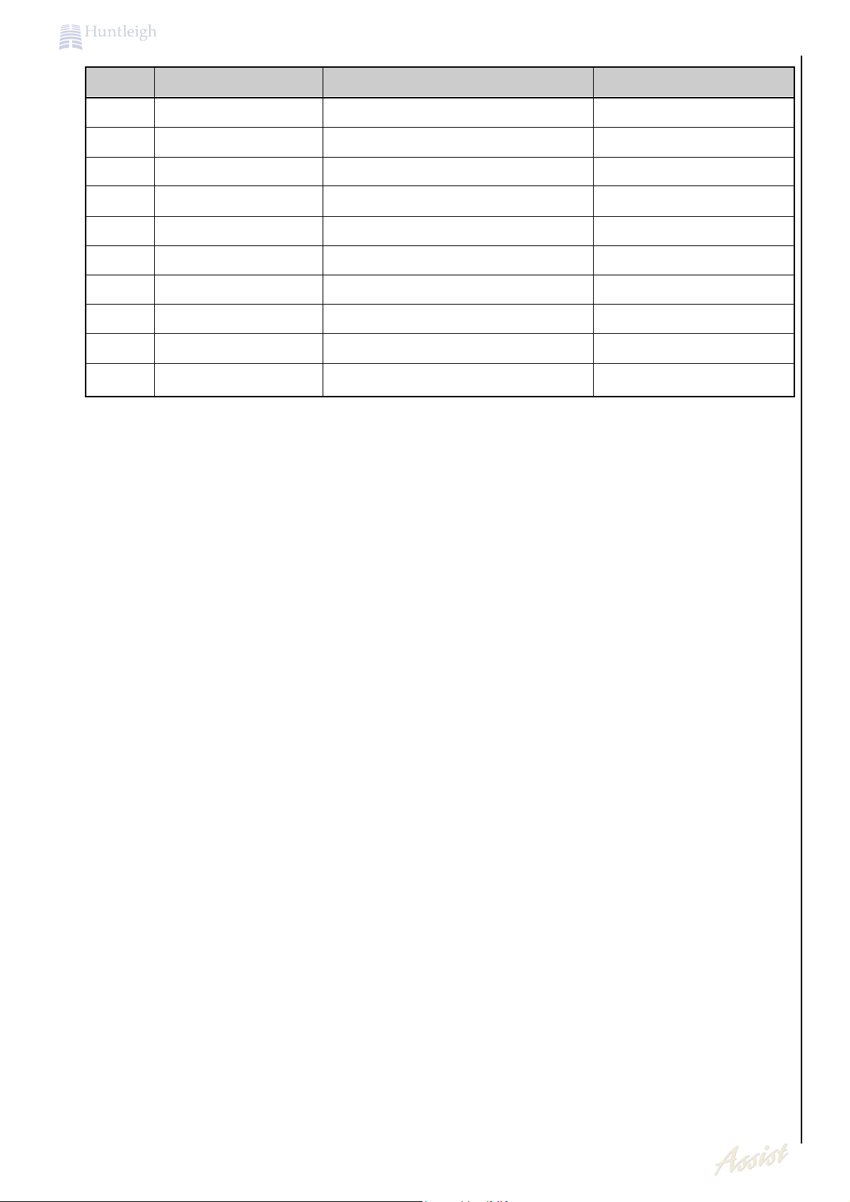
Ultra I/O Parallel port usage
Pin No. Signal Name Description Alternative Function
138 AUDIO_MODE Audio Amp Control line Parallel Port Data-bit 0
137 AUDIO_MUTE Audio Amp Control line Parallel Port Data-bit 1
136 AUDIO_SHUTDOWN Audio Amp Control line Parallel Port Data-bit 2
135 VPP_ENABLE PCMCIA Vpp-enable Parallel Port Data-bit 3
134 SMRESET Smart card reset Parallel Port Data-bit 4
133 SMCS1 Smart-Card Chip Select Parallel Port Data-bit 5
132 SMCS2 Smart-card Chip Select Parallel Port Data-bit 6
19
Main PCB Circuit Description
HEALTHCAR
E
Pin No. Signal Name Description Alternative Function
131 SMCS3 Smart-card Chip Select Parallel Port Data-bit 7
129 SMWP Smart card write protect Printer Acknowledge
128 SMDETECT Smart card detect Printer Busy
127 UNUSED N/A Printer Paper End
126 UNUSED N/A Printer Select
144 UNUSED N/A Printer Strobe
143 SRESET# AVR Programming Printer Auto Line Feed
142 MISO AVR Programming Printer Error
141 MOSI AVR Programming Printer initialise
140 SCK AVR Programming Printer Selected
The Ultra I/O chip has two 16550A compatible UART's. The base address of which can be set
during configuration mode. The PMA sets these addresses to 2F8h and 3E8h for the PCB's
COM2 and COM3 respectively, in software
5.17 Serial Ports
The 32Khz oscillator is used for triggering the watchdog circuit. During the initial boot up the
IPL/BIOS does not trigger the watchdog. With the additional circuitry described below, this clock
triggers the watchdog. A link (LK10) is used to select between constant triggering of the
watchdog (Pads 2 and 3 soldered together for development purposes) or switched out after
30secs (pads 1 and 2 soldered together normal position).
There is also a link (LK11) present to allow this clock to be connected to the display controller.
This enable self refresh of the display DRAM during standby mode of the display controller.
With out this the display controller cannot refresh DRAMS during standby mode.
5.18 32KHz Oscillator
The Reset circuit is controlled by a MAX706. This monitors the 3.3V supply rail and keeps reset
asserted when it falls below 3.08V. It releases the reset after 200ms after the supply rises
above this threshold. The IC also has a built in watchdog that needs to be toggled before an
internal timer reaches 1.6secs. The watchdog output is pulled low when this timeout period is
reached but it does not cause a reset, therefore the watchdog output is shorted to the manual
reset input (MR).
The 555 timer is used in mono-stable mode in order to inhibit the watchdog for 30secs during
boot up. This is to allow time for QNX to run the application, which will then trigger the
watchdog accordingly. A NAND logic is used to divert either the 32Khz clock or the SC400
watchdog trigger output to the Watchdog input on the MAX706 according to the state of the
555 Timer output.
5.19 RESET and Watch Dog Circuit

20
Main PCB Circuit Description
HEALTHCAR
E
The 65550 is a 64-bit high performance multi-media flat panel / CRT GUI accelerator controller.
The 64-bit graphics accelerator engine has functions for Bit Block Transfer (BitBLT), hardware
cursor, and other functions intensively used in Graphical User Interfaces (GUIs). The 65550
controller is fully compatible with VGA at the register level.
The 65550 implements independent multimedia-capture and display systems on-chip,
although this is not utilised on the PMA
The 65550 supports a wide variety of monochrome and colour LCD panels. For monochrome
panels, up to 64 gray scales are supported. Up to 4096 different colours can be displayed on
passive STN LCD's and up to 16M colours on 24-bit active matrix (e.g. TFT) LCD's.
Along with the LCD panel support the 65550 can drive an RGB monitor simultaneously. RGB
outputs are available pin 57, 58, and 60 along with the necessary VSYNC and HSYNC on pins
64, and 65. The RGB outputs need to be pulled down with 75R resistor in order to produce the
required impedance of the line of 37.5R (this is because the resistor is in parallel with the
monitors 75R)
Due to the need for simultaneous display at ½ VGA on LCD and full VGA on monitor the
connection for the LCD output pins are P0-4 and P8-11 and the LCD display driver set up for
Dual scan 16bit mode. This has the effect of showing only the top half of the full VGA screen on
the LCD while masking the rest (because the low half data never gets to the LCD). The other
flat panel signals are: -
SHFCLK
- shift clock used to clock one byte of data to the display
LP
- line pulse to indicate end of data line
FLM
- FRAME LATCH PULSE to indicate end of one screen display
M
- Modulation signal to modulate dc signal to prevent premature aging of the liquid crystal
from dc voltages. (can cause shadowing if set incorrectly)
5.20 Graphics Controller
An extensive set of registers control the graphics system. These registers are a combination of
registers defined by the Video Graphics Array (VGA) standard, and others that support graphics
modes that have colour depths, resolutions, and hardware acceleration features that go well
beyond the original VGA standard. Some of the registers are directly accessible at various I/O
addresses. They may be read-only or write-only, and some must be read from and written to
at different I/O addresses. Most of the other registers are accessed through a sub-addressing
arrangement. The index of the desired register is written to an index register, and then the
desired register may be read from or written to through a data port. Almost all of these subaddressed registers are both readable and write-able. Still other registers are directly
accessible at various memory addresses, and here too, almost all of these registers are both
readable and write-able.
Part of the VGA standard requires the VGA graphics system to take the place of either the IBM
Monochrome Display and Printer Adaptor (either MDPA or MDA) or the IBM Colour Graphics
Adaptor (CGA). The MDA has registers at I/O addresses 3B4-3B5 and 3BA, and a character
buffer (not a frame buffer -- the MDA is a text-only device) within the memory address range of
B0000-B7FFF.
5.21 Memory Addressing
5.22 Contrast and Brightness Control
The contrast and brightness of the touch screen are adjusted by two digital potentiometers. The
digital pots are configured to use up and down inputs by connecting them to a tri-stated port
during power up. This is to allow full control by software over the position of the wiper. By
incrementing or decrementing the wiper 64 times, puts the wiper either at the top or bottom of
the range accordingly. This places it in a known position where it can keep track of any
adjustments, so as to indicate the setting on screen.

21
Main PCB Circuit Description
HEALTHCAR
E
The power supply sequencing of the LCD display and backlight can be fully controlled by the
65550 timing registers. The backlight has an additional on off control signal generated by the
SC400 as a power saving feature.
The touch screen control is used to calculate the position of a 'pen' or finger on the resistive
touch screen and to send this information to the SC400 via serial or parallel format. In order to
read the XY co-ordinates of the current position, it first applies a current drive to the x plane
resistive film and read the voltage present on the Y-plane film. It reads this voltage with internal
10 bit A-to-D's, to get the X co-ordinate. It will then calculate the Y co-ordinate in a similar
manner by applying current drive to the Y-plane and reading the voltage on the x plane. The
touch screen controller can sample the position 200 times a second with a 1.8432MHz clock
attached.
The chip detects if the 'pen' is in contact with the touch screen and flagged on the PEN_OFF pin
(0V pen is touching screen, 5V is not touching the screen). When new data is available for
reading from the parallel output buffers, the NEW_DATA pin is pulled low. Any new data that is
available is sent via the serial port immediately.
The parallel interface uses three control lines to fetch the data, COEN which is the chip enable
line X_SELECT which is used to address X or Y data and BHE to address the upper or lower
byte of the 10bit data. When X_SELECT is 0 the Y-data is accessed, when X_SELECT is 1 the
X-data is accessed. The 10bit data is formatted for data transfer with the BHE signal.
5.23 Touch Screen Controller
The keypad interface is 4 by 4 matrix of rows and columns, allowing up to 16 keys to be
matrixed. They are read and written to by the Ultra I/O GPIO pins 15-24. The 4 columns are
strobed low individually and read back on the rows, the key pressed can be calculated by
knowing which column was strobed and which row had been pulled low by that column.
5.24 Key Pad Interface
Module left and right audio signals are pre-filtered via an IC prior to a Power Amplifier. The
bandwidth is 72Hz to 19.5KHz and has a unity gain over this range. The Capacitors C165 and
C163 add high pass filter stage with internal 20kW resistors with a roll off at 80Hz.
The mono beep in from the SC400 is added to each of these channels prior to the internal
volume control stage.
A DC signal level, on the DCVOL input adjusts the internal volume control. This is externally
produced by the digital potentiometer, controlled by the SC400. The digital pot is set up in the
same manner as described for the backlight and contrast above, and is controlled by the
SC400 GPIO.
Control of the Line/HP and speaker outputs is achieved by the state of the shutdown, mode,
mute and HP-sense inputs of the LM4834
Additional external circuitry was added to muted the line outs to the base station when the
headphones are plugged in without affecting the headphone volume. Stripping the AC
component off the headphone signal, and comparing the DC level to a known DC reference of
2.5V does this. The comparator gets the 2.5V reference from the resistor divider R104 + R89.
With the headphones removed the sockets internal switch pulls the positive input of the
comparator to ground, this causes the output of the comparator to remain low and thus
allowing the MAX324, an analogue switch, to remain in its normally closed position. When the
headphones are plugged in the AC signal is removed by the C30, R85 low-pass filter with a
roll-off of 1Hz. This causes the output of the comparator to go high, opening the analogue
switch and therefore muting the Lineout signals.
The logic contained in U15 is used to mute the internal speaker of the PMA unit when either the
headphones or base station is attached.
5.25 Touch Screen Controller
22
Fetal Assist Overview
HEALTHCAR
E
The obstetric module co-processor is a Hitachi 3048H device with 128K internal Flash memory.
It communicates with the host embedded 486 processor via a bespoke 44 way interconnection scheme which maps an 8K dual port RAM on the host into the address space of
the H8 co-processor.
The H8 works in tandem with an Analog Devices Digital Signal processor, ADSP2105.
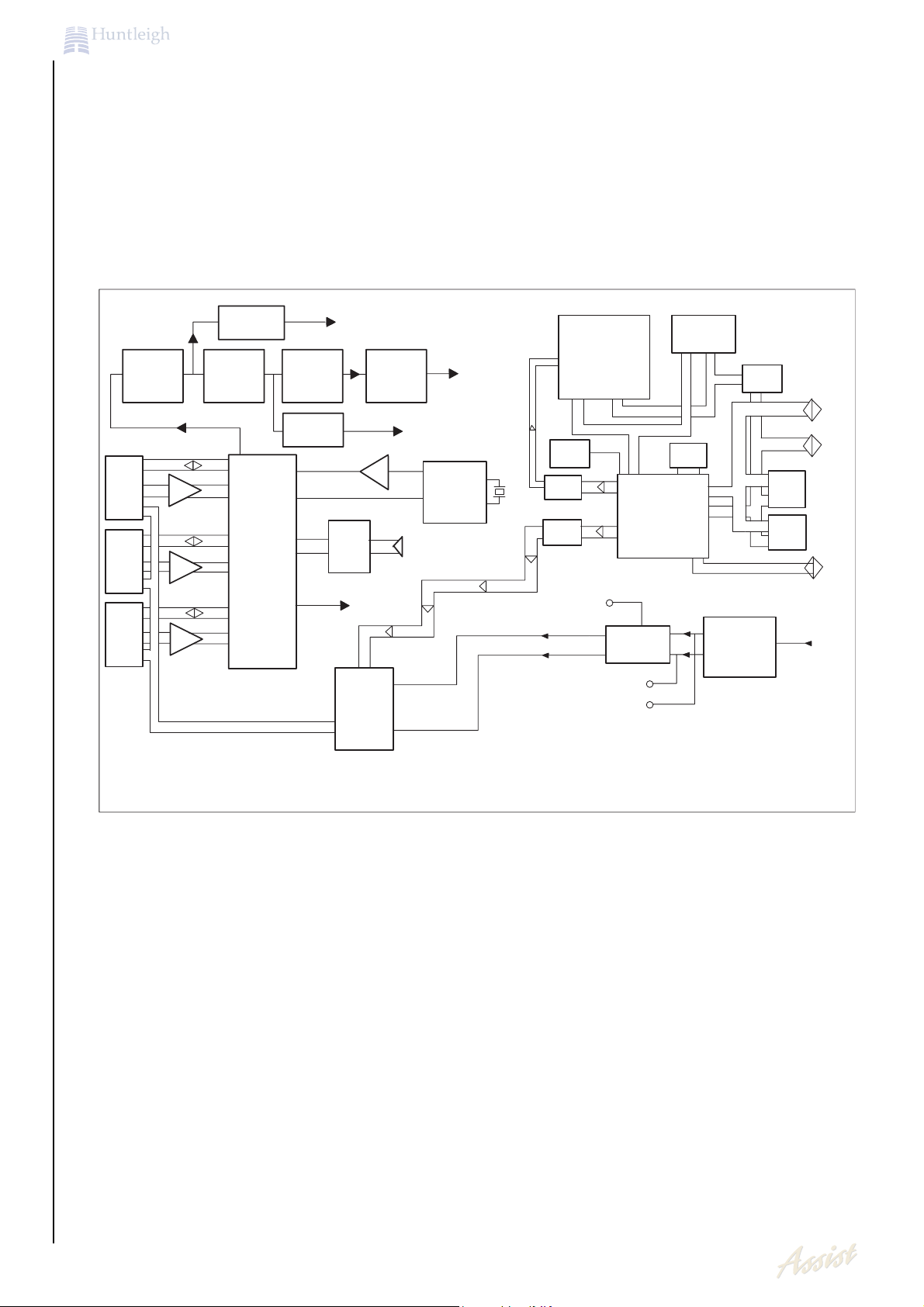
6. Fetal Assist overview
The circuit design has been implemented in the form of a hybrid of conventional analogue
circuits, a DSP, and a microcontroller system. The microcontroller establishes a digital
communications link with the Host unit, controls switching of the various analogue circuit
blocks, controls the operation of the DSP IC, and fulfils a number of other functions.
The Fetal Assist has been split up into several sections as shown below for clarity.
6.1 Microcontroller section
6.1.1 3048 microcontroller
The device runs at 9.8304MHz in mode 6 from an external crystal (X1) to give a linear
addressing range of 16Mbytes with external data and address bus. The data bus in all
address ranges in fixed at 8 bit. The embedded firmware is programmed into the internal
flash of the H8 using the intrinsic boot facility of the device via serial port SC1 in
conjunction with Hitachi flash download and programming software running on a PC Host.
The code segment is similarly limited to 128kbyte . The code size at present is typically
about 40kbytes.
Intrinsic functions of the H8/3048F
Obstetric Module Block Diagram
ULTRASOUND
ACCESSORY
PORTS
PORT 1
PORT 2
PORT 3
LOW-PASS
FILTER
FMD BANDPASS
FILTER
MICRO
A/D
RAM
DSP
MICRO
ULTRASOUND
OSCILLATOR/
TIMING
A/D
WATCHDOG/
RESET
LOGIC
----------------------------------
------
----
------------
-----------------------------------------
LOGIC
DSP ADDRESS BUS
VREF
±10V
DSP DATA BUS
MICROCONTROLLER
DUAL VOLTAGE
REGULATOR ±10V
+12V
-12V
H8
EEPROM
±12V
DATA
LATCH
DATA
ADDRESS
CONTROL
POWER SUPPLY
±12V SWITCHING
REGULATOR
FLASH
RAM
+5V FROM
HOST
HOST
HOST
HOST
----------------
DATA
LATCH
POWER
SWITCHING
MICRO
A/D
DIGITAL GAIN
CONTROL
AUDIO OUT (TO HOST)
RF
AMP
DATA
HIGH-PASS
FILTER
AMP
AMP
AMP
TOCO
U/S
TOCO
U/S
TOCO
MULTIPLEX
U/S
ANTI_ALIAS
FILTER
AUDIO
LIMITER
TOCO
23
Fetal Assist Overview
HEALTHCAR
E
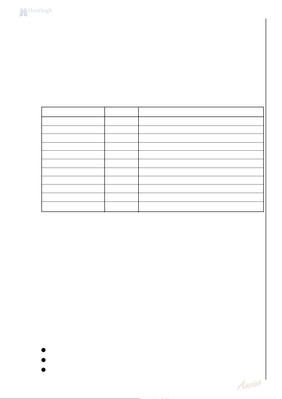
H8/3048 memory map
Address range CS line Function
0x000000-1FFFFF CS0 128Kb internal ROM including vectors
0x200000-3FFFFF CS1 29F016 chip select (2Mb Application Software)
0x400000-401FFF CS2 Not used
0x600000-6001FF CS3 DSP data write (data)
0x800000-9FFFFF CS4 DSP interface logic strobe (control)
0xA00000-BFFFFF CS5 68128 128k RAM CS (not used at present)
0xC00000-DFFFFF CS6 analogue multiplexer latch clock
0xE00000-E01FFFF CS7 8K DPRAM data
0xE02000-E02007 CS7 8 x DPRAM semaphore
0xFFEF10-FFFF00 4kb internal RAM
0xFFFF1C-FFFFFF Special function registers (internal)
Chip selects CS0-7 are automatically asserted by the H8 when the current access
address falls within the ranges defined in its bus control registers. Memory areas marked
as not used are not available to the co-processor software as the pins are reserved for
other purposes
External flash in the form of a 29F016 holds the application software for the host. This is
uploaded to the host 486 via a software protocol upon demand. The H8 otherwise makes
no use of this device beyond the facility to read, program and erase it as a result of
explicit instructions issued by the host.
External RAM is provided as a 128K 68128 device for optional storage of data or 'C'
compiler variables. At present the link map for the IAR 'C' compiler used to generate the
embedded code has been organised such that only internal RAM is used and the 68128
RAM may be omitted. This restricts the obstetrics co-processor software to a 4Kbyte limit
for the data segment.
Microcontroller section details
The H8 microcontroller section embodies the following functions :-
(a) Non-vvolatile data storage :-
Up to 4k bytes of data can be stored in a 24C32 I2C type serial EEPROM. This device is
driven by software algorithms using port lines PB.1 and PB.2. The internal synchronous
serial interface of the H8 is not used. The obstetrics application does not currently require
non-volatile data storage.
(b) DSP program download
The ADSP2105 runs a DSP algorithm to process the Doppler signal from the ultrasound
probe. This DSP code is embedded within the H8 program memory at a fixed address
within the H8 flash programming operation. The DSP code sections required are :-
MEM.A20 checks DSP presence, located at 1FE00
FHRUS.A20 performs fetal heart rate determination, located at 1D600
USECG.A20 improved heart rate algorithm, located at 1E000
Microcontroller functionality

24
Fetal Assist Overview
HEALTHCAR
E
The H8 uploads this code to the DSP chip at start-up by asserting P4.7 to generate an
interrupt to the ADSP2105. From this point the code transfer to the DSP memory takes
place over a parallel link comprising 8 bit latch (U8 a 74HC374) in conjunction with
handshaking implemented as Bus Grant from the DSP (read as data bit 15 by the H8)
and a Bus Request from the H8 generated by writing to the HC374 latch.
(c) DSP bidirectional data interface
When running its signal processing algorithm, the DSP will continually output its results to
the H8 and accept update commands for the AGC control and the basal signal threshold
required. This is performed synchronously over a serial link using the SCI0 module of the
H8. The system clock for the DSP is generated by the H8 as its PHI (system clock out) pin
running at 9.8304MHz. The serial data transfer clock is synthesised by the ADSP2105
which connects directly to the SCIO SCLK in of the H8.
(d) US signal level determination
The integrated level of signal from the ultrasound transducer is measured by an internal
10 bit analogue to digital converter (AN0). This value is processed by the H8 over a finite
time period and reported back to the DSP over the serial link.
(e) Toco signal input
The filtered output from the Toco transducer is read as analogue input AN1. This gives a
10 bit resolution. A buffering arrangement within the H8 firmware averages this reading.
(f) AGC and FMD
The H8 periodically samples the values of the AGC and filtered fetal Doppler signals.
These are fed back into the DSP algorithm for adaptive processing. This technique is
used as the ADSP2105 does not possess its own internal A/D conversion sections.
(g) Accessory (probe) identification
The H8 reads the data contained within the identification component located within the
connector of an attached probe to determine the combination and position of attached
probes. Each probe has a DS2430 single wire EEPROM pre-configured to hold its
accessory type and Assist module category. Based on this information, which is read
every 100msec, the H8 will configure the module hardware to match the probe
arrangement. Each ID is read on pins PB.5 to PB.3 respectively. Each ID read operation
requires approximately 3msec to complete.
(h) Hardware multiplexing
The 'plug and play' feature of the obstetrics module permits an ultrasound, toco or event
marker transducer to be inserted into any of the accessory connection ports. The
hardware will only permit one of each type of probe to be present at any given time
although duplicate types may be attached without causing hardware problems. The H8
uses the detected ID information to select the appropriate routing channels through
analogue multiplexers . These are controlled by static signals latched into a 74HC273 chip
by writing to address C0000.
(i) Dual Port RAM
By writing and reading the semaphore area of the host DP RAM the H8 implements a
parallel data transfer interface with the host 486 which has intrinsic handshaking. In host
control mode, the H8 firmware responds to commands issued by the host 486 which
allow it to download its own application code as well as gain access to the other
hardware facilities of the module. Upon receipt of a 'Run' command, the H8 executes the
fetal monitor code loop which periodically stuffs four bytes into fixed locations of the Dual
Port RAM. These are recovered by the host 486 (without data handshake) as required, to
implement the end user obstetric function application.
 Loading...