


Huntleig
h
HEALTHCARE
Mini Pump
Service Manual
Issue 2
SER0004 Nov 2001


Mini Pump Service Manual Contents
AMENDMENT RECORD
Amendment Incorporated by Date
1
2
3
4
5
6
7
8
9
10
11
12
13
14
15
16
17
18
19
20
21
22
23
24
25
26
27
28
29
30
Issue 2 Contents
Nov 2001 SER0004 Page (i)

Contents Mini Pump Service Manual
Contents Issue 2
Page (ii) SER0004 Nov 2001

Mini Pump Service Manual Contents
Contents
CHAPTER 1
Introduction ....................................1
About This Manual ......................................1
Warnings, Cautions and Notes ............................2
Technical Description .....................................3
Operating Principle...................................3
System Start Up Sequence ..............................5
Low Pressure Alarm (Electronic Units Only) ......................6
Low Pressure Alarm (All Units) ............................6
Low Pressure Alarm Protocol (Electronic Units Only) .................6
Power Failure Alarm (Electronic Units Only)......................6
Battery Management (Electronic Units Only) .....................7
CHAPTER 2
Maintenance ...................................1
Pump Maintenance Checks .................................1
Pump Soak/Break-in Times..................................2
Pump Service .........................................2
CHAPTER 3
Pump Repair ...................................1
General ............................................1
Removing the Pressure Control Knob ............................3
Installing the Pressure Control Knob .............................3
Disassembling the Pump Filter ................................5
Assembling the Pump Filter .................................5
Disassembling the Rear Case ................................5
Assembling the Rear Case ..................................5
Disassembling the New Style Bed Hook ...........................7
Installing the New Style Bed Hook ..............................7
Removing the Old Style Bed Hook ..............................9
Installing the Old Style Bed Hook...............................9
Removing the Compressor Inlet Filter............................11
Installing the Compressor Inlet Filter ............................11
Removing the New Style AV Mounts ............................13
Replacing the New Style AV Mounts ............................13
Removing the Old Style AV Mounts .............................15
Issue 2 Contents
Nov 2001 SER0004 Page (i)

Contents Mini Pump Service Manual
Installing the Old Style AV Mounts .............................15
Removing the Compressor Mounting Bracket........................17
Installing the Compressor Mounting Bracket ........................17
Removing the Compressor Bump Stops ..........................17
Installing the Compressor Bump Stops ...........................18
Replacing the Compressor Silencer Bag ..........................19
Replacing the Bellows Armature Assemblies and Pivots ..................21
Replacing the Compressor Armature Pivots ........................21
Replacing the Compressor Valve Bodies ..........................23
Replacing the ‘E’ Stack Assembly..............................25
Replacing the Coil Assembly ................................25
Replacing the Compressor Assembly ............................25
Replacing the Pressure Control Module...........................27
Replacing the Alarm Monitoring PCB ............................29
Changing the Battery ....................................31
Replacing the Neon Indicator Light .............................33
Replacing the Microswitch..................................35
Replacing the Terminal Block ................................35
Replacing the Pressure Control Flaps and Air Bag .....................37
Replacing the Pressure Control Assembly .........................39
Replacing the Synchronous Motor (Gearbox), Rotor Stator Assembly ...........41
Replacing the Side Panel Mains/Power On/Off Switch ...................43
Replacing the Side Panel Mains/Power Lead ........................43
Replacing the Fuses.....................................43
Replacing the Snap-lock Connectors ............................45
Removing the Front Case ..................................46
Installing the Front Case ..................................46
Pump Label Sets ......................................47
CHAPTER 4
Troubleshooting .................................1
General ............................................1
Low Pressure fault indicated (checks without dismantling the pump) ............2
Loss of Output Pressure (checks by dismantling the pump) .................3
Low Pressure Alarm Fault ..................................4
Air Not Alternating (continuous pressure fault) ........................4
Loss of Electrical Power ...................................4
Contents Issue 2
Page (ii) SER0004 Nov 2001

Mini Pump Service Manual Contents
Circuit Diagrams .......................................5
CHAPTER 5
Testing ......................................1
Pump Flow, Pressure and Function Test ...........................1
Electrical Testing .......................................5
PCB Functional Tests (Electrical Units Only) .........................6
Functional Tests (Mechanical Units Only) ..........................7
CHAPTER 6
Technical specification..............................1
CHAPTER 7
Parts list ......................................1
CHAPTER 8
Service Contact Details .............................1
Issue 2 Contents
Nov 2001 SER0004 Page (iii)

Contents Mini Pump Service Manual
Contents Issue 2
Page (iv) SER0004 Nov 2001

Mini Pump Service Manual Introduction
CHAPTER 1
INTRODUCTION
1 About This Manual
Huntleigh Healthcare strongly recommend that their equipment is only serviced by trained
personnel and provide courses for customers who wish to become licensed to service their
own equipment. In no event will Huntleigh Healthcare be responsible for any service
performed by customers or third parties.
This manual contains information on maintenance, servicing, repair, troubleshooting and testing for
the range of pressure regulated pump units; pump models within the range are as follows:
AlphaXcell (Electronic)AlphaXcell (Mechanical)
•
AlphaRelief (Electronic)
•
Aura (Electronic)
•
AlphaTrancell (Mechanical)
•
AlphaBed (Mechanical)
•
AlphaCare (Mechanical)
•
Pump models are available for use world wide – model codes are shown in Table 1, while for country
codes and power supply details refer to Table 2.
Table 1 - Product Range Distribution
Model Code Country Code
AlphaXcell (Electronic) ALX 01 to 10
AlphaXcell (Mechanical) ALX 11
AlphaRelief ALR 01 - 10
Aura ALS 01 - 10
AlphaTrancell ALT 01 - 10
AlphaBed ALB 01 - 10
AlphaCare ALC 01 - 10
Issue 2 Chap 1
Nov 2001 SER0004 Page 1

Introduction Mini Pump Service Manual
Table 2- Country Codes/Power Supplies
Mains Power
Country Code Country
Voltage (Volts AC) Frequency (Hz)
01 UK 220 - 240 50
02 Germany 220 - 240 50
03 USA 110 - 120 60
04 Euro 220 - 240 50
05 France 220 - 240 50
06 Japan 100 50/60
07 Italy 220 - 240 50
08 Australia 220 - 240 50
09 Rest of World 220 - 240 50
10 Holland 220 - 240 50
11 Rest of World 110 - 120 60
Warnings, Cautions and Notes
WARNINGS given in this manual identify possible hazards in procedures or conditions which, if not
correctly followed, could result in death, injury or other serious adverse reactions.
Cautions given in this manual identify possible hazards in procedures or conditions which, if not
correctly followed, could result in equipment failure or damage.
Notes given in this manual are used to explain or amplify a procedure or condition.
WARNINGS:
BEFORE PERFORMING ANY SERVICE OR MAINTENANCE PROCEDURES,
ENSURE THAT THE EQUIPMENT HAS BEEN ADEQUATELY
DECONTAMINATED.
VOLTAGES IN EXCESS OF 30 VOLTS RMS OR 50 VOLTS DC CAN, IN
CERTAIN CIRCUMSTANCES, BE LETHAL. WHEN WORKING ON
EQUIPMENT REQUIRING EXPOSURE TO LIVE, UNPROTECTED
CONDUCTORS WHERE SUCH VOLTAGES ARE PRESENT, EXTREME CARE
MUST BE EXERCISED.
WHEN AN UNSERVICEABLE MAINS LEAD/POWER CORD FITTED WITH A
NON-REWIREABLE PLUG IS REMOVED FROM THIS EQUIPMENT, THE
LEAD/CORD AND THE PLUG MUST BE DESTROYED AND DISPOSED OF
SAFELY. TO AVOID THE DANGER OF ELECTRIC SHOCK THE PLUG MUST
NEVER BE INSERTED IN ANY POWER OUTLET.
Chap 1 Issue 2
Page 2 SER0004 Nov 2001

Mini Pump Service Manual Introduction
2 Technical Description
The pressure regulated pump units listed in section 1 provide pressurised air for alternating pressure
mattress systems which are used in aiding the prevention, treatment and management of pressure
ulcers.
Pressurised air is fed to a range of support systems, mattresses, seat cushions etc., which support
patients at risk of developing pressure ulcers.
All pumps are self-contained units powered by the single phase mains/power supply. Low air
pressure and power failure alarm functions are included in some models, and pump output pressure
is adjustable by means of a rotary control mounted on the unit front panel.
Operating Principle
Refer to Figure 1 for details of the pneumatic circuit. All pumps have two pressurised air outlets, air
from the outlets is fed to separate cells or groups of cells in the mattress or cushion via a rotary valve.
The support cells are continuously inflated and deflated utilising a ten minute cycle. During the cycle,
air is pumped from one outlet for 4 minutes 10 seconds, there is then a period of 50 seconds where
air is pumped from both outlets. Air is then pumped from the other outlet for 4 minutes 10 seconds,
followed by a 50 second period where air is supplied from both outlets. During the period when air is
suppled from a single outlet to one group of cells, the opposing outlet is vented to atmosphere,
deflating the corresponding cells.
Issue 2 Chap 1
Nov 2001 SER0004 Page 3

Introduction Mini Pump Service Manual
COMPRESSOR
PRESSURE
CONTROL
PRESSURE
CONTROL
MODULE
MICROSWITCH
ALTERNATING CELLS
1
A
A
A
A
A
B
B
B
A2
A
A
B
B
A3
A
B
B
A4
A
B
B
EXCEPTION:
Aura has 9 alternating cells but no static cells.
A
B
A
A
B
A
A
B
A
B
B
A
A
B
B
A
A
B
B
A
A
B
B
ROTOR/
STATOR
OUTLET
PORTS
M
HEAD
SECTION
(STATIC)
A
B
B
C
C
C
A
B
B
C
C
C
A
B
B
C
C
C
A
B
B
C
C
C
KEY
= INFLATED
= DEFLATED
Figure 1 - Pneumatic Diagram and Pressure Variations
For the Aura mini pump small adjustments can be made to cell pressure using the comfort control
knob on the pump unit. This is a patient comfort feature to make small adjustments to the softness or
firmness of the support cells. All other mini pumps have a pressure adjustment control that must be
set to the patient weight in accordance with the instructions given in the relevant user manual and/or
the pump labels.
The range of air pressure delivered by the series of pumps varies, as does the achievable flow rate.
One extreme of pressure range can be adjusted by obtaining access to a screw under the pressure
control knob; see Table 3 for details of pressure variations. The range achievable is fixed by the
pressure control spring, only the set pressure can be reset.
Chap 1 Issue 2
Page 4 SER0004 Nov 2001

Mini Pump Service Manual Introduction
Table 3 - Air Pressure/Flow Rates
Pump
Model
ALX 20-24 57-73 Yes 6 3
ALR 20-24 72-92 Yes 6 3
ALS 83-87 Less than 110 Comfort
ALT 25-35 65-81* Yes 6 3
ALB 25-35 80-100 Yes 6 3
ALC 25-35 80-100 Yes 6 3
* Holland pumps (ALT10) only - max pressure is 80-100 mmHg
Pump units may be divided, into two types, Mechanical and Electronic. Major differences between
the two types of pump unit are as follows:
Alarm indicators - mechanical type has a neon indicating low air pressure, also an illuminated
•
mains/power on/off switch. The electronic type incorporates an alarm monitoring PCB driving a
number of LED indicators and audible warning sounder. See Table 4 for visual indicator
details.
Minimum
Pressure
(mmHg)
Maximum
Pressure
(mmHg)
Adjustable
Pressure
Range
control only
Minimum Flow
Rate at 20 mmHg
back pressure
(litres/minute)
3.25 2.25
Minimum Flow
Rate at 50
mmHg
(litres/minute)
• Air outlets - mechanical type has simple push-on connectors (except ALX11 which has
snap-lock type connectors). The electronic type utilises snap-lock type connectors.
Table 4 - Product Visual Indicators
Model Code ALB ALC ALT ALR ALX ALX ALS
Mechanical (M)
or
Electrical (E)
Indicator
Illuminated Mains/Power Switch X X X X
On X X X
Wait X X
Low Pressure X X XXXXX
Power Fail X X X
System Start Up Sequence
All pump types must be connected to the appropriate mains/power supply via a suitable plug.
After a mechanical pump is switched on the start up sequence is as follows:
MMME EME
•
The ON/OFF switch lever will be illuminated green.
Issue 2 Chap 1
Nov 2001 SER0004 Page 5

Introduction Mini Pump Service Manual
The red ‘low pressure’ indicator will be illuminated. When operating pressure is achieved, the
•
low pressure indicator will be extinguished automatically.
After an electronic pump is switched to ‘Run’ the start up sequence is as follows:
The unit performs a diagnostic self test, illuminating all LED indicators and sounding the
•
audible alarm. If an internal fault is sensed or a problem with the wiring of the mains/power
sense switch, the pump will remain in this state. If the self test is successful then the start up
sequence will proceed.
On start up, the low pressure alarm will be inhibited until one minute after the low pressure
•
signal is deactivated. The amber WAIT indicator will be illuminated while the low pressure
alarm is inhibited. (See Low pressure Protocol) Other functions will work as normal.
Note: Aura (ALS) model has no WAIT indicator; apart from this one difference, however, the Aura
pump performs the same as the other electronic pump units.
Low Pressure Alarm (Electronic Units Only)
When the alarm is activated, the red LOW PRESSURE indicator will flash, in combination with an
audible warning which increases in pitch with time. The alarm can be reset by momentarily switching
the pump to ‘Stand by’ and then back to ‘Run’. Alternatively, the alarm will automatically reset after
15 minutes provided that the low pressure switch is not activated during this time. If however the low
pressure switch is activated (for more than 15 seconds) during this time, the timer will reset to zero
and the alarm will continue for a further 15 minutes.
Low Pressure Alarm (All Units)
On all pump units except the ALS model the low air pressure alarm will be activated on or before
5 mmHg and deactivated before the pressure reaches 17 mmHg.
For the ALS model only, the low air pressure alarm will be activated on or before 50 mmHg and
deactivated at or before 82 mmHg.
Low Pressure Alarm Protocol (Electronic Units Only)
The low pressure alarm will be activated only when the requirements of the low pressure alarm
protocol have been met by a sequence of low pressure signals. The system is designed to detect low
pressure fault conditions without responding to spurious signals due to patient movement, mattress
cell crossover, short term tube disconnection etc.
In order to generate a low pressure alarm the system must detect three low pressure switch closure,
of 15 seconds duration each, within a 25 minute period. There will be a 2 minute lockout between the
first and second switch closures as well as between second and third switch closures. The lockout
period is to allow temporary disconnection of tubing.
In addition to the above, a wait period of 25 minutes is allowed on start up. During this time the low
pressure alarm is inhibited to allow inflation of the mattress to operating pressure. If, during this wait
period, the low pressure switch is activated (i.e., the system is up to pressure), the wait period will be
terminated 1 minute later, and normal protocol is obeyed thereafter.
Power Failure Alarm (Electronic Units Only)
In the event of a power failure, the red POWER FAIL indicator will flash in combination with an
audible warning which increases with time.
If the power supply is restored, the audible alarm will stop, but the indicator will remain illuminated
(continuously) until the system is reset. Resetting, by switching the pump to ‘Stand by’ and then back
to ‘Run’, will clear all alarm indications.
Chap 1 Issue 2
Page 6 SER0004 Nov 2001

Mini Pump Service Manual Introduction
The power failure alarm is initiated by the removal of the mains/power supply from the unit for a
period of more than 5 seconds, by a means other than operation of the ‘Run/Standby’ switch. A drop
in the supply voltage below the minimum supply specification will be interpreted as a supply failure. If
power is restored within 5 seconds, no alarm is given and normal operation is resumed.
A battery backup supply provides power to operate the visual and audible alarm.
Battery Management (Electronic Units Only)
On switching the pump to ‘Run’, the processor automatically initiates a standard charge sequence
(3 mA) for a predetermined period. On completion of the standard charge period, a trickle charge
(0.9 mA) will be applied to the battery for the remainder of the operating period.
When discharging during a power failure alarm, the battery supply will be shut down in a controlled
manner if the terminal voltage falls below 4.6 V before the alarm duration has expired.
Issue 2 Chap 1
Nov 2001 SER0004 Page 7

Introduction Mini Pump Service Manual
Chap 1 Issue 2
Page 8 SER0004 Nov 2001

Mini Pump Service Manual Maintenance
CHAPTER 2
MAINTENANCE
1 Pump Maintenance Checks
If any parts are found to be damaged they must be replaced in accordance with Chapter 3, Pump
Repair.
1.1 Visually inspect the following for damage, wear and potential faults:
Note : If any parts require repairing or replacing then refer to the Huntleigh Healthcare service
manual.
1.1.1 Check outer casings for damage.
1.1.2 Functionally check switches and control knobs.
1.1.3 Ensure hanging brackets are secure and located.
1.1.4 Check outlet ports and connecting points for damage.
1.1.5 Ensure feet are secure and present.
1.1.6 Check fuses are satisfactory.
1.1.7 If a gauge is fitted ensure the glass is not cracked or damaged.
1.1.8 Check that there is no damage to the mains/power connector if fitted.
1.1.9 Check labels are present, located correctly and legible.
1.1.10 Ensure LED’s are not cracked.
1.2 Remove the compressor lid (Refer to Chap. 3, Section 22) and visually inspect the following for
damage, wear, and potential faults:
Note : If any parts require repairing or replacing then refer to Chap 3, Pump Repair.
1.2.1 Coil/’E’ stack assembly.
1.2.2 Elbows and connectors.
1.2.3 Bellows.
1.2.4 Security of compressor.
1.2.5 Integrity of filters and gaskets.
1.2.6 Valve body assembly.
1.2.7 Armature blades.
1.2.8 Pivot points.
1.2.9 Silencer bags.
1.2.10 Valve shuttle assembly.
Issue 2 Chap 2
Nov 2001 SER0004 Page 1

Maintenance Mini Pump Service Manual
Once the compressor has been visually inspected connect to a power supply and run, this is to
ensure the compressor is working and that there is flow/pressure at the outlet port of the pump.
Check for any excessive noise and vibration.
2 Pump Soak/Break-in Times
2.1 A pump must be soaked/broken-in for the following reasons:
Note : Soaking/breaking-in consists of running the pump with the outlet ports blocked.
To ensure that the pump is at normal running temperature prior to pneumatic performance
•
tests being carried out.
To stress test major/critical parts which have been replaced or repaired.
•
2.2 All pumps should be soaked/broken-in for a period of 30 to 60 minutes prior to any pneumatic
performance test being carried out. This is because the compressor bellows need to warm up
to reach normal output.
2.3 If any of the following major/critical components have been replaced or repaired, then it is
recommended that the pump be soaked/broken-in for 12 hours prior to being tested:
Valve body.
•
Silencer Bag.
•
Printed Circuit Boards (PCB) if applicable.
•
Compressor.
•
Rotary Valve Assembly.
•
3 Pump Service
A pump should be serviced every 12 months. To carry out a service on the pump, do the following:
3.1 Carry out the Pump Maintenance Checks (Section 1).
3.2 Replace the following components:
3.2.1 Silencer bag (Refer to Chapter 3, Section 22).
3.2.2 Pivot points (Refer to Chapter 3, Section 24).
3.2.3 Bellow assemblies (Refer to Chapter 3, Section 23).
3.2.4 Valve bodies (Refer to Chapter 3, Section 25).
3.2.5 Compressor filter (Refer to Chapter 3, Section 12).
3.2.6 Compressor gasket (Refer to Chapter 3, Section 22).
3.2.7 Pump case filter (Refer to Chapter 3, Section 4).
3.2.8 AV mounts (Refer to Chapter 3, Section 14 - new style, Section16 - old style).
3.2.9 Internal rechargeable battery (Refer to Chapter 3, Section 31).
Chap 2 Issue 2
Page 2 SER0004 Nov 2001

Mini Pump Service Manual Maintenance
3.3 Reassemble the pump and soak/break-in for the recommended time (Refer to Section 2).
3.4 Carry out a flow, pressure and function test on the pump in accordance with Chapter 5.
3.5 Carry out electrical tests on the pump in accordance with Chapter 5.
Issue 2 Chap 2
Nov 2001 SER0004 Page 3

Maintenance Mini Pump Service Manual
Chap 2 Issue 2
Page 4 SER0004 Nov 2001

Mini Pump Service Manual Pump Repair
CHAPTER 3
PUMP REPAIR
1 General
This chapter details repair procedures for the range of pump units listed in Chapter 1, Page 1,
Table 1. All repairs should be carried out by Huntleigh approved service personnel.
After carrying out a service or any repairs, the pump must be soak tested/broken-in for the
recommended time (Refer to Chapter 2) and tested for serviceability. The table below defines the test
requirements which must be carried out following certain repairs:
To carry out a flow, pressure and function test on the pump refer to Chapter 5.
To carry out the electrical tests on the pump refer to Chapter 5.
Table 5- Repair to Testing Requirements
Components / Assemblies
Compressor Yes Yes
Pressure Control Yes Yes
Rotors & Stators Yes Yes
Silencer Bag Yes No
Coils Yes Yes
Elbows & Connectors Yes No
AV Mounts Yes Yes
PCB Yes Yes
Front Casing Yes No
Rear Casing No No
Battery No Yes
Switches No Yes
Fuse No Yes
Flow/Pressure & Function
Test
Electrical Safety
Electrical Connectors No Yes
Mains/Power Lead No Yes
Issue 2 Chap 3
Nov 2001 SER0004 Page 1

Pump Repair Mini Pump Service Manual
20
10
30
Pin (if fitted)
40
Figure 2 - Removing the Control Knob
Table 6 - Control Knob Part List
Item Part Number Description Qty
10 500484 Control Knob (MK2) 1
20 500304 Knob Arbour 1
30 500318 Pin (if fitted) 1
40 500316 Front Case 1
Note : The obsolete MK1 control knobs are fully interchangeable with the MK2 control knobs. If the
MK1 control knob needs replecing, replace it with the MK2 version.
Chap 3 Issue 2
Page 2 SER0004 Nov 2001

Mini Pump Service Manual Pump Repair
2 Removing the Pressure Control Knob
Note : Removing the control knob avoids possible damage and allows the pump to sit on a flat
surface without rocking.
2.1 Locate the slot at the rear of knob (Fig 2, Item 10) and inserta3mmflatpoint screwdriver.
2.2 Lever the screwdriver upward to lift the knob off the three retaining prongs.
3 Installing the Pressure Control Knob
Note : When installing the pressure control knob, ensure that the small prong sits in its own housing.
Then, the two larger prongs will line up correctly.
Aura (Pin fitted)
Turn knob arbour clockwise to it’s full extent. Fit control knob in the position shown below.
ENSURE
90° MOVEMENT
SMALL PRONG
AlphaRelief / AlphaBed / AlphaCare / AlphaTrancell ALT10 (No pin fitted)
Turn knob arbour counter-clockwise to it’s full extent. Fit control knob in the position shown below.
ENSURE
SMALL PRONG
270° MOVEMENT
AlphaXcell / AlphaTrancell ALT01-09 (Pin fitted)
Turn knob arbour counter-clockwise to it’s full extent. Fit control knob in the position shown below.
ENSURE
SMALL PRONG
180° MOVEMENT
3.1 Carefully position the knob (Fig 2, Item 10) so that the prongs are correctly aligned with the
recesses in the knob arbour (Fig 2, Item 20)
3.2 Press the knob into place on the arbour and ensure that it is correctly seated.
Issue 2 Chap 3
Nov 2001 SER0004 Page 3

Pump Repair Mini Pump Service Manual
10
50
20
40
30
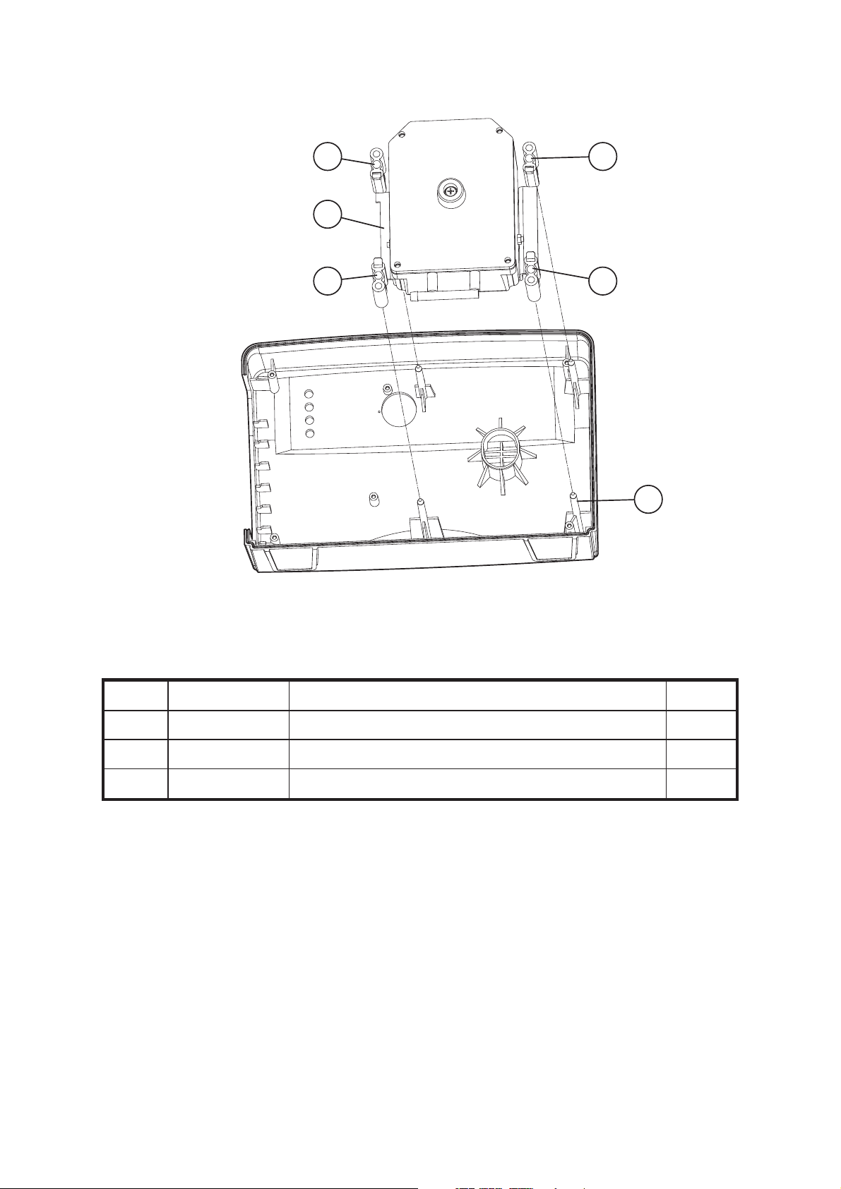
Figure 3 - Removing and Replacing the Pump Filter
Table 7 - Pump Filter Part List
Item Part Number Description Qty
10 500340 Felt Filter 1
20 500327 Filter Plate 1
30 500317 Rear Case 1
40 FAS223 Pan Head Screw PT 3 Dia x 10 Pozi 1
50 FAS225 Pan Head Screw PT 3 Dia. x 16 Pozi 4
Chap 3 Issue 2
Page 4 SER0004 Nov 2001

Mini Pump Service Manual Pump Repair
4 Disassembling the Pump Filter
4.1 Remove the centre screw (Fig 3, Item 40) retaining the filter plate (Fig 3, Item 20) in the rear
case (Fig 3, Item 30).
4.2 Carefully remove the filter plate and felt filter (Fig 3, Item 10) from the rear case. Discard the
old filter.
5 Assembling the Pump Filter
5.1 Install a new filter (Fig 3, Item 10) in the filter plate (Fig 3, Item 20) ensuring that the curved
edge is at the top.
5.2 Ensure that the filter is correctly positioned over the boss in the filter plate then fit the filter plate
to the rear case (Fig 3, Item 30) and secure with the screw (Fig 3, Item 40).
6 Disassembling the Rear Case
Note : It is necessary to remove the rear case from the front case to allow access to all internal pump
connections.
6.1 Remove the front panel control knob (Refer to Page 3, Section 2).
6.2 Place the pump on a flat, clean surface with the case front face down.
6.3 Unscrew and remove the four corner screws (Fig 3, Item 50).
6.4 Carefully remove the rear case assembly (Fig 3, Item 30) from the case front.
7 Assembling the Rear Case
7.1 Assembly of the rear case is in the reverse order of disassembly.
Issue 2 Chap 3
Nov 2001 SER0004 Page 5

Pump Repair Mini Pump Service Manual
10
50
20
30
40
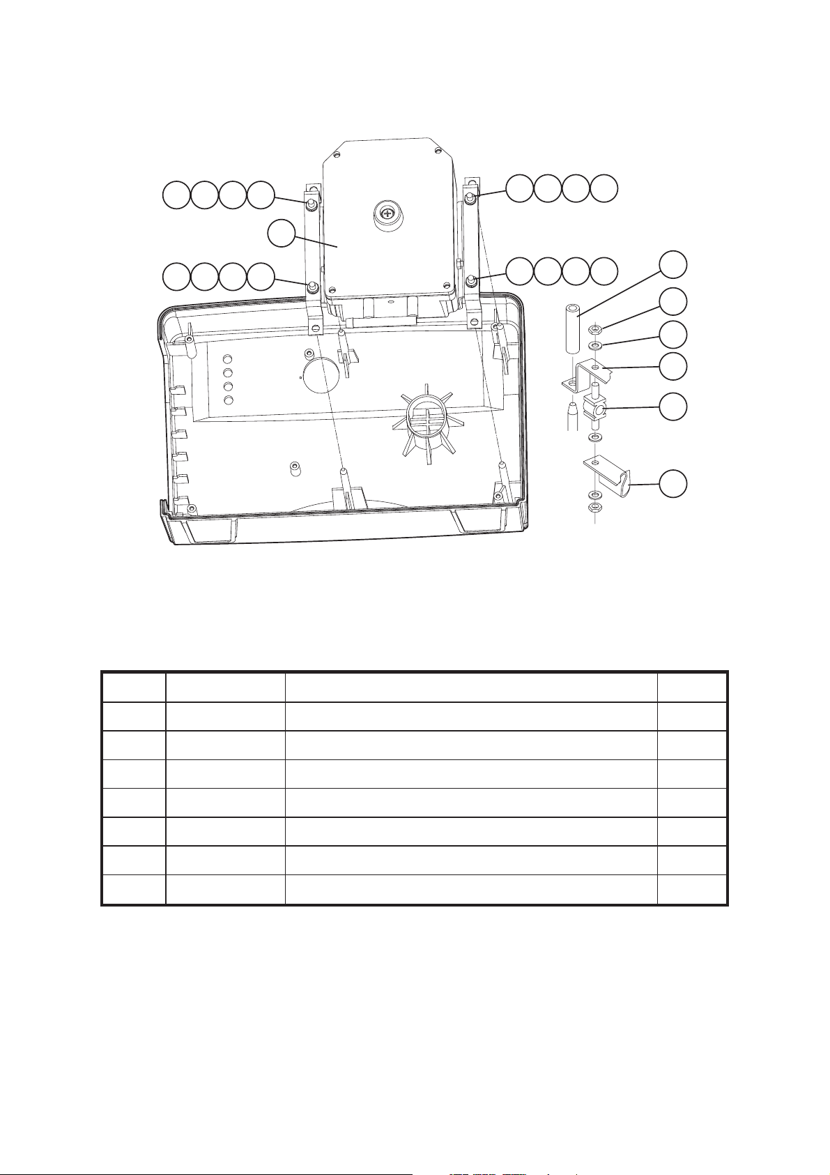
Figure 4 - Replacing the New Style Bed Hook
Table 8 - New Style Bed Hook Part List
Item Part Number Description Qty
10 500495 Bed Hook (New Style) 1
20 500496 Hook Plate (Left Hand) 1
30 500497 Hook Plate (Right Hand) 1
40 FAS223 Pan Head screw PT 3 Dia. x 10 8
50 500381 Rubber foot 8
Chap 3 Issue 2
Page 6 SER0004 Nov 2001

Mini Pump Service Manual Pump Repair
8 Disassembling the New Style Bed Hook
8.1 Remove the pressure control knob from the pump (Refer to Page 3, Section 2).
8.2 Remove the pump rear case (Refer to Page 5, Section 6).
Note : The bed hook brackets are right and left handed.
8.3 Hold a hook plate (Fig 4, Item 20 or 30) in position and remove the four securing screws (Fig 4,
Item 40) from the inside of the pump rear case. Release the hook plate from the rear case and
lift clear.
8.4 If necessary repeat Section 8.3 to remove the other hook plate and bed hook (Fig 4, Item 10).
9 Installing the New Style Bed Hook
Note : Replacement Old Style Bed Hooks are no longer available. The Old Style Rear Case
assembly will not accommodate the New Style Bed Hook so where Old Style Bed Hooks must
be replaced it will be necessary to obtain all the parts listed in Table 8, plus the rear case (Item
30 in Table 6).
Note : For step 9.2, remember to place the left-hand bracket on the right and the right-hand bracket
on the left, since their relative positions will be reversed when they are presented to the rear
case assembly.
9.1 Assembly of the new Pump Filter is in the reverse order of disassembly. Make sure the slots in
the Filter Housing Plates (Fig 4, Item 20) are uppermost in the positions shown in Fig 4.
9.2 Lay the left-hand (Fig 4, Item 20) and the right-hand (Fig 4, Item 30) brackets on a hard flat
surface with their rubber pads face down and their shaped heads pointing inward.
9.3 Ensure the bed hook (Fig 4, Item 10) is correctly placed to the left-hand and right-hand slots
where the coating has been removed. Firmly press home the bed hook until it clicks into place.
9.4 Lay the rear case assembly, on a hard flat surface, with its back uppermost. Turn over the bed
hook subassembly and place into the rear case assembly.
9.5 Position one bracket and press it firmly until it clicks into place. Repeat this process for the
other bracket.
9.6 Turn over the rear case assembly and fit four securing screws to each bracket.
9.7 Assemble the rear case to the pump (Refer to Page 5, Section 7).
9.8 Install the pressure control knob (Refer to Page 3, Section 3).
Issue 2 Chap 3
Nov 2001 SER0004 Page 7

Pump Repair Mini Pump Service Manual
10
30
20
30
40
Figure 5 - Replacing the Old Style Bed Hooks
Chap 3 Issue 2
Page 8 SER0004 Nov 2001

Mini Pump Service Manual Pump Repair
Table 9 - Old Style Bed Hook Part List
Item Part Number Description Qty
10 N/A Bed Hook - Left Hand 1
20 N/A Bed Hook - Right Hand 1
30 N/A Hook Plate 1
40 N/A Pan Head screw PT 3 Dia. x 10 Pozi 6
Note :The old bed hook bracket assemblies are left and right handed. Replacements are no longer
available.
10 Removing the Old Style Bed Hook
10.1 Remove the pressure control knob from the pump (Refer to Page 3, Section 2).
10.2 Remove the pump rear case (Refer to Page 5, Section 6).
10.3 Hold a hook plate (Fig 5, Item 30) in position and remove the three securing screws (Fig 5,
Item 40) from the inside of the rear case.
10.4 Carefully remove the hook plate and its bed hook (Fig 5, Item 10 or 20).
10.5 Repeat Section 10.3 and 10.4 for the other hook plate and bed hook if required.
Note : The above procedure will not be necessary when changing the old bed hooks for the new bed
hook which needs the new rear case assembly.
11 Installing the Old Style Bed Hook
11.1 When refitting the old bed hook brackets, replacement is the reversal of the above procedure.
11.2 Ensure correct orientation of the left and right-handed assemblies. (The spring on the right
hand assembly is colour coded red).
11.3 Position the hook and spring assembly on the rear case, install the hook plate and hold it in
place while inserting the three securing screws from the inside of the rear case.
11.4 Assemble the rear case to the pump (Refer to Page 5, Section 7).
11.5 Install the pressure control knob (Refer to Page 3, Section 3).
Issue 2 Chap 3
Nov 2001 SER0004 Page 9

Pump Repair Mini Pump Service Manual
10
20
30
40
Figure 6 - Replacing the Compressor Filter Assembly
Table 10 - Compressor Filter Assembly Part List
Item Part Number Description Qty
10 502003 Compressor Assy 230V 50Hz 11K/T 1
502002 Compressor Assy 110V 60Hz 5K/T (USA) 1
502007 Compressor Assy 100V 50/60Hz 4.5K/T (Japan) 1
20 500320 ‘F’ Tube Connector REF
30 500410 Filter Retaining Clip 1
40 500417 Inlet Filter 1
Chap 3 Issue 2
Page 10 SER0004 Nov 2001

Mini Pump Service Manual Pump Repair
12 Removing the Compressor Inlet Filter
12.1 Remove the pressure control knob from the pump (Refer to Page 3, Section 2).
12.2 Remove the rear case assembly (Refer to Page 5, Section 6).
12.3 Carefully pull the filter retaining clip (Fig 6, Item 30) from the ‘F’ tube connector (Fig 6, Item 20).
12.4 Remove and discard the old inlet filter (Fig 6, Item 40).
13 Installing the Compressor Inlet Filter
13.1 Locate a new inlet filter (Fig 6, Item 40) over the air intake hole in the case of the compressor
assembly (Fig 6, Item 10).
13.2 Carefully reposition the filter retaining Clip (Fig 6, Item 30) on the ‘F’ tube connector (Fig 6,
Item 20) to retain the inlet filter (Fig 6, Item 40). Make sure the clip is fitted with the longer arm
downward if appropriate.
13.3 Assemble the rear case to the pump (Refer to Page 5, Section 7).
13.4 Install the pressure control knob from the pump (Refer to Page 3, Section 3).
Issue 2 Chap 3
Nov 2001 SER0004 Page 11
Pump Repair Mini Pump Service Manual
20 20
10
20 20
30
Figure 7 - Replacing the New Style AV Mounts
Table 11 - New Style AV Mounts Part List
Item Part Number Description Qty
10 500124 Compressor Mounting Bracket 1
20 500416 AV Mount 4
30 N/A Mounting Pins 4
Chap 3 Issue 2
Page 12 SER0004 Nov 2001

Mini Pump Service Manual Pump Repair
14 Removing the New Style AV Mounts
14.1 Remove the pressure control knob from the pump (Refer to Page 3, Section 2).
14.2 Remove the rear case assembly (Refer to Page 5, Section 6).
14.3 Carefully lift the compressor, mounting bracket (Fig 7, Item 10) and AV mounts (Fig 7, Item 20)
from the mounting pins (Fig 7, Item 30).
14.4 Remove the AV mounts from the mounting bracket and discard them.
15 Replacing the New Style AV Mounts
15.1 Fit new AV mounts (Fig 7, Item 20) of the same type to the mounting bracket (Fig 7, Item 10).
15.2 Carefully fit the compressor, mounting bracket and AV mounts to the mounting pins (Fig 7,
Item 30) in the pump case. Ensure that all four AV mounts are correctly located on the
mounting pins.
15.3 Assemble the rear case to the pump (Refer to Page 5, Section 7).
15.4 Assemble the pressure control knob to the pump (Refer to Page 3, Section 3).
Issue 2 Chap 3
Nov 2001 SER0004 Page 13
Pump Repair Mini Pump Service Manual
10
20
30
40
50
10
20
30
40
40
30
10
20
Figure 8 - Replacing the Old Style AV Mounts
Table 12 - Old Style AV Mounts Part List
10
20
30
40
70
30
40
10
20
60
Item Part Number Description Qty
10 N/A AV Mounting Bracket 2
20 198375 AV Mount 4
30 N/A AV Mount Nut 8
40 N/A Washer 12
50 Ref Table 14 Compressor 1
60 N/A Compressor Mounting Bracket (Part) 1
70 N/A Spacers 4
Chap 3 Issue 2
Page 14 SER0004 Nov 2001

Mini Pump Service Manual Pump Repair
16 Removing the Old Style AV Mounts
Note : Replacements are not available for the old style AV mounts.
16.1 Remove the pressure control knob from the pump (Refer to Page 3, Section 2).
16.2 Remove the rear case assembly (Refer to Page 5, Section 6).
16.3 Remove the securing spacers (Fig 8 Item 70) and carefully lift the compressor (Fig 8, Item 50)
and AV bracket assembly (Fig 8, Items 10, 20, 30, 40, 60) from the mountings.
16.4 Release the to AV mount nuts (Fig 8, Item 30) and washers (Fig 8, Item 40) and remove the
two AV mounting brackets (Fig 8, Item 10) from the AV mounts (Fig 8, Item 20).
16.5 Release the bottom AV mount nuts and washers and remove the four AV mounts from the
compressor mounting bracket (Fig 8, Item 60).
17 Installing the Old Style AV Mounts
17.1 Fit four replacement AV mounts (Fig 8, Item 20) to the compressor mounting bracket (Fig 8,
Item 60) and secure with washers (Fig 8, Item 40) and nuts (Fig 8, Item 30).
17.2 Fit the two AV mounting brackets (Fig 8, Item 10) to the AV mounts and secure with washers
and nuts.
17.3 Carefully fit the compressor (Fig 8, Item 50) and AV bracket assembly (Fig 8, Items 10, 20, 30,
40, 60) to the mountings in the pump case and fit securing spacers (Fig 8 Item 70).
17.4 Assemble the rear case to the pump (Refer to Page 5, Section 7).
17.5 Install the pressure control knob (Refer to Page 3, Section 3).
Issue 2 Chap 3
Nov 2001 SER0004 Page 15

Pump Repair Mini Pump Service Manual
10
40
50
50
30
60
20
40
Figure 9 - Replacing Mounting Brackets and Bump Stops
Chap 3 Issue 2
Page 16 SER0004 Nov 2001

Mini Pump Service Manual Pump Repair
Table 13 - Compressor Mounting Brackets and Bump Stops Part List
Item Part Number Description Qty
10 165310 Upper Bump Stop 1
20 165310 Lower Bump Stop 1
30 500124 Compressor Mounting Bracket (New Style) 1
N/A Compressor Mounting Bracket (Old Style) 1
40 FAS160 Washer M4 Plain 2
50 FAS051 Screw Pan Head Pozi M4x6mm 2
60 FAS095 Screw Pan Head Pozi M4 x 10 mm 3
18 Removing the Compressor Mounting Bracket
18.1 Remove the compressor/AV bracket assembly from the pump case and disassemble AV
mounts as described on Page 13, Section 14 (new style AV mounts) or Page 15, Section 16
(old style AV mounts. Section 16.4 should be omitted if old style AV mounts are not to be
replaced.
Note : Figure 7 Illustrates the new style AV mount system. Compressor mounting bracket to
compressor assembly methods are the same for both old and new style AV mount systems.
18.2 Remove screw, washer and lower bump stop (Fig 9, Items 50, 40, 20) from the compressor
mounting bracket (Fig 9, Item 30).
18.3 Remove three screws (Fig 9, Item 60) and detach the mounting bracket from the compressor.
19 Installing the Compressor Mounting Bracket
19.1 Fit replacement mounting bracket (Fig 9, Item 30) same type (if required) to the compressor.
Ensure that the four pegs are correctly located and secure the mounting bracket to the
compressor with three screws (Fig 9, Item 60).
19.2 Fit the screw, washer and lower bump stop (Fig 9, Items 50, 40, 20) to the mounting bracket.
19.3 Assemble AV mounts and fit the compressor/AV bracket assembly into the pump case as
described in Section 15 (new style AV mounts) or Section 17 (old style AV mounts). Section
17.2 may be omitted.
20 Removing the Compressor Bump Stops
20.1 Remove the compressor/AV bracket assembly from the pump case as described in Section
14.1, 14.2 and 14.3 (new style AV mounts) or Section 16.1, 16.2 and 16.3 (old style AV
mounts).
Note : Figure 7 illustrates the new style AV mount system. Bump stop to compressor and bump stop
to compressor mounting bracket assembly methods are the same for both old and new style
AV mount systems.
20.2 Remove screw, washer and upper bump stop (Fig 9, Items 50, 40, 10) from the compressor lid.
Issue 2 Chap 3
Nov 2001 SER0004 Page 17

Pump Repair Mini Pump Service Manual
20.3 Remove screw, washer and lower bump stop (Fig 9, Items 50, 40, 20) from the compressor
mounting bracket.
21 Installing the Compressor Bump Stops
21.1 Fit screw, washer and replacement upper bump stop (Fig 9, Items 50, 40, 10) to the
compressor lid.
21.2 Fit screw, washer and replacement lower bump stop (Fig 9, Items 50, 40, 10) to the
compressor mounting bracket.
21.3 Refit the compressor/AV bracket assembly to the pump case as described in Page 13, Section
15.2, 15.3 and 15.4 (new style AV mounts) or Page 15, Section 17.3, 17.4 and 17.5 (old style
AV mounts).
30
20
60
40
10
70
50
80
Figure 10 - Compressor Silencer Bag
Chap 3 Issue 2
Page 18 SER0004 Nov 2001

Mini Pump Service Manual Pump Repair
Table 14 - Compressor Silencer Bag Part List
Item Part Number Description Qty
10 502003 Compressor Assy 230V 50Hz 11K/T 1
502002 Compressor Assy 110V 60Hz 5K/T (USA)
502007 Compressor Assy 100V 50/60Hz 4.5K/T (Japan)
20 502301 Compressor Lid 1
30 FAS054 Screw Countersunk Pozi M4 x 12 mm 4
40 BP032 Compressor Gasket 1
50 502055 Silencer Bag 1
60 500320 ‘F’ Tube Connector 1
70 N/A Silencer Bag Outlet Tubes REF
80 N/A Silencer Bag Inlet Tubes REF
22 Replacing the Compressor Silencer Bag
22.1 Remove the compressor/AV bracket assembly from the pump case (Refer to Page 13, Section
14.1, 14.2 and 14.3 (new style AV mounts) or Page 15, Section 16.1, 16.2 and 16.3 (old style
AV mounts)).
22.2 Remove four screws (Fig 10, Item 30) and carefully lift off the compressor lid (Fig 10, Item 20)
and gasket (Fig 10, Item 40) from the compressor assembly (Fig 10, Item 10). Discard the
gasket.
22.3 Disconnect the outlet tubes (Fig 10, Item 70) of the silencer bag (Fig 10, Item 50) from the ‘F’
tube connector (Fig 10, Item 60).
22.4 Disconnect the inlet tubes (Fig 10, Item 80) of the silencer bag from the valve bodies.
22.5 Fit a new silencer bag and gasket, then replace the compressor lid by reversing operations
detailed in Section 22.4, 22.3 and 22.2.
22.6 Refit the compressor/AV bracket assembly to the pump case (Refer to Page 13, Section
15.2,15.3 and 15.4 (new style AV mounts) or Page 15, Section 17.3, 17.4 and 17.5 (old style
AV mounts)).
Issue 2 Chap 3
Nov 2001 SER0004 Page 19
Pump Repair Mini Pump Service Manual
30
10
20
40
Figure 11 - Bellows Armature Assembly and Pivots
Table 15- Bellows Armature Assembly Part List
Item Part Number Description Qty
10 502054 Bellows Armature Assembly Left-Hand 230V 50Hz 1
BP215 Bellows Armature Assembly Left-Hand 110V 60Hz 1
20 502053 Bellows Armature Assembly Right-Hand 230V 50Hz 1
BP214 Bellows Armature Assembly Right-Hand 110V 60Hz 1
30 BP043 Armature Pivot 2
40 BP554 Valve Body 2
Chap 3 Issue 2
Page 20 SER0004 Nov 2001

Mini Pump Service Manual Pump Repair
23 Replacing the Bellows Armature Assemblies and Pivots
23.1 Remove/disassemble the compressor/AV bracket assembly and remove the silencer bag
(Refer to Page 19, Section 22.1, 22.2,22.3 and 22.4).
23.2 Using long nosed pliers, extract the armature blade, part of bellows armature assembly (Fig 11,
Item 10 or 20) from the armature pivot (Fig 11, Item 30)
23.3 Unclip the bellows, part of bellows armature assembly from the valve body (Fig 11, Item 40)
and lift the bellows armature assembly clear of the compressor.
23.4 Repeat 23.2 and 23.3 as required to remove the other bellows armature assembly.
23.5 Discard the old bellows armature assembly and fit a replacement of the same type by reversing
the actions carried out in Section 23.3 and 23.2.
23.6 Fit a new silencer bag and gasket, then replace the compressor lid (Refer to Page 19 and
reverse the operations carried out in Section 22.4, 22.3 and 22.2).
23.7 Refit the compressor/AV bracket assembly to the pump case (Refer to Page 13, Section 15.2,
15.3 and 15.4 (new style AV mounts) or Page 15, Section 17.3, 17.4 and 17.5 (old style AV
mounts)).
23.8 Test the assembly. Note, in order to achieve flow/pressure performance, the new bellows may
have to be heated with a hot air gun whilst operating. This anneals the bellows permanently
and alters the pressure/flow characteristics.
Caution: The bellows will be damaged if overheated.
24 Replacing the Compressor Armature Pivots
24.1 Remove/disassemble the compressor/AV bracket assembly and remove the silencer bag
(Refer to Page 19, Section 22.1, 22.2, 22.3 and 22.4).
24.2 Extract the armature blade from the pivot (Refer to Section 23.2).
24.3 Use a sharp, pointed tool and carefully extract the pivot (Fig 11, Item 30) from the hole in the
compressor casing.
24.4 Discard old armature pivots and replace with same type. Carefully insert the new pivot into the
compressor casing using a small screwdriver to ensure the slot in the pivot is aligned to accept
the armature blade.
24.5 Fit the armature blade to the pivot reversing the actions carried out in Section 23.2.
24.6 Fit a new silencer bag and gasket, then replace the compressor lid (Refer to Page 19 and
reverse the operations carried out in Section 22.4, 22.3 and 22.2).
24.7 Refit the compressor/AV bracket assembly to the pump case (Refer to Page 13, Section 15.2,
15.3 and 15.4 (new style AV mounts) or Page 15, Section 17.3, 17.4 and 17.5 (old style AV
mounts)).
Issue 2 Chap 3
Nov 2001 SER0004 Page 21

Pump Repair Mini Pump Service Manual
30
70
60
20
60
70
50
40
Figure 12 - Compressor Valve Bodies
Table 16 - Compressor Valve Bodies Part List
Item Part Number Description Qty
10 BP554 Valve Body Assy, Blue
2
(Each valve body contains items 20 to 70)
20 BP351 Valve Body 1
30 FAS027 Screw, Hex Head 4BA x 3/4 1
40 FAS013 4BA Full Nut 1
50 BP039 Valve Body Washer 2
60 BP037 Valve Flap 2
70 BP038 Valve Flap Securing Pad 2
Chap 3 Issue 2
Page 22 SER0004 Nov 2001

Mini Pump Service Manual Pump Repair
25 Replacing the Compressor Valve Bodies
25.1 Remove/disassemble the compressor/AV bracket assembly and remove the silencer bag
(Refer to Page 19, Section 22.1, 22.2, 22.3 and 22.4).
25.2 Unclip the bellows, part of bellows armature assembly from the valve body (Refer to Page 20,
Fig 11, Items 10 or 20 and 40).
25.3 Unscrew and remove the securing nut (Fig12, Item 40) on the side of the compressor housing.
25.4 Remove the valve body (Fig 12, Item 20) and Valve body washers (Fig 12, Item 50).
25.5 Remove the valve flap securing pads and the valve flaps (Fig 12, Items 70 and 60)
25.6 Discard the old valve body and replace with the same type.
25.7 Repeat Sections 25.3 to 25.6 as necessary to replace the other valve body.
25.8 When replacing the valve flaps and valve flap securing pads, make sure that the valve flap sits
flat over the hole in the valve body and the valve securing pad is pushed fully on to the lug.
25.9 Position the replacement valve body and secure with screw (Fig 12, Item 20) and nut. Fit the
bellows to the valve body.
25.10 Fit a new silencer bag and gasket, then replace the compressor lid (Refer to Page 19 and
reverse the operations carried out in Section 22.4, 22.3 and 22.2).
25.11 Refit the compressor/AV bracket assembly to the pump case (Refer to Page 13, Section 15.2,
15.3 and 15.4 (new style AV mounts) or Page 15, Section 17.3, 17.4 and 17.5 (old style AV
mounts)).
Issue 2 Chap 3
Nov 2001 SER0004 Page 23

Pump Repair Mini Pump Service Manual
10
50
20
30
40
60
Figure 13 - ‘E’ Stack and Coil Assembly
Table 17 - ‘E’ STACK and Coil Assembly Part List
Item Part Number Description Qty
10 BP028 ‘E’ Stack 1
20 FAS048 Pan Head Screw M3 x 25 mm Pozi 2
30 FAS002 Washer - 6BA Anti-Vib. 2
40 502050 Coil Assembly 230V 50Hz (black/white leads) 1
502062 Coil Assembly 110V 60Hz (grey leads) 1
BP275 Coil Assembly 100V 50/60Hz (blue leads) 1
50 165303 Grommet 1
60 502304 Compressor Case 1
Chap 3 Issue 2
Page 24 SER0004 Nov 2001

Mini Pump Service Manual Pump Repair
26 Replacing the ‘E’ Stack Assembly
Note : After doing work in either Section 26 or 27 the pressure/flow characteristics can be altered by
moving the coil assembly/’E’ stack nearer or further from the armature magnets. This can be
done by adjusting screws (Fig 13, Item 20). Ensure the screws are tightened afterwards.
26.1 Remove/disassemble the compressor/AV bracket assembly and remove the silencer bag
(Refer to Page 19, Section 22.1, 22.2, 22.3 and 22.4).
26.2 Unscrew and remove the two screws and anti-vibration washers (Fig 13, Items 20 and 30)
which secure the ‘E’ stack/coil assembly (Fig 13, Items 10 and 40).
26.3 Withdraw the ‘E’ stack/coil assembly from the compressor case as far as the electrical wires will
allow.
26.4 Carefully remove the ‘E’ stack from the coil assembly.
26.5 Replace the ‘E’ stack by reversing the operations carried out in Section 26.4, 26.3 and 26.2.
26.6 Fit a new silencer bag and gasket, then replace the compressor lid (Refer to Page 19 and
reverse the operations carried out in Section 22.4, 22.3 and 22.2).
26.7 Refit the compressor/AV bracket assembly to the pump case (Refer to Page 13, Section 15.2,
15.3 and 15.4 (new style AV mounts) or Page 15, Section 17.3, 17.4 and 17.5 (old style AV
mounts)).
27 Replacing the Coil Assembly
27.1 Remove/disassemble the compressor/AV bracket assembly and remove the silencer bag
(Refer to Page 19, Section 22.1, 22.2, 22.3 and 22.4).
27.2 Remove the ‘E’ stack/coil assembly as described in Section 26.2 and 26.3.
27.3 Disconnect the compressor electrical wires from the terminal block. Carefully cut the cable ties
from the pneumatic tubing/cable loom as required.
27.4 Feed the compressor electrical wires through the compressor case cable grommet (Fig 13,
Item 50).
27.5 Remove the ‘E’ stack/coil assembly from the compressor case (Fig 13, Item 60) and carefully
separate the coil from the ‘E’ stack.
27.6 Replace the coil assembly by reversing the operations carried out in Section 27.5, 27.4, 27.3
and 27.2; fit new cable ties where required.
27.7 Fit a new silencer bag and gasket, then replace the compressor lid (Refer to Page 19 and
reverse the operations carried out in Section 22.4, 22.3 and 22.2).
27.8 Refit the compressor/AV bracket assembly to the pump case (Refer to Page 13, Section 15.2,
15.3 and 15.4 (new style AV mounts) or Page 15, Section 17.3, 17.4 and 17.5 (old style AV
mounts)).
28 Replacing the Compressor Assembly
28.1 Disconnect the compressor electrical wires as described in Section 27.3.
Issue 2 Chap 3
Nov 2001 SER0004 Page 25

Pump Repair Mini Pump Service Manual
28.2 Remove the compressor air inlet filter and clip from the ‘F’ tube connector, then disconnect the
‘F’ tube connector from the silencer bag outlet tubes (Refer to Page 11, Section 12.1, 12.2,
12.3 and 12.4).
28.3 Remove the compressor/AV bracket assembly from the pump case (Refer to Page 13, Section
14.1, 14.2 and 14.3 (new style AV mounts) or Page 15, Section 16.1, 16.2 and 16.3 (old style
AV mounts)).
28.4 Remove the compressor mounting bracket (Refer to Page 17, Section 18).
28.5 Fit a replacement compressor assembly by reversing the actions detailed above.
40 80
70
10
20
30
60
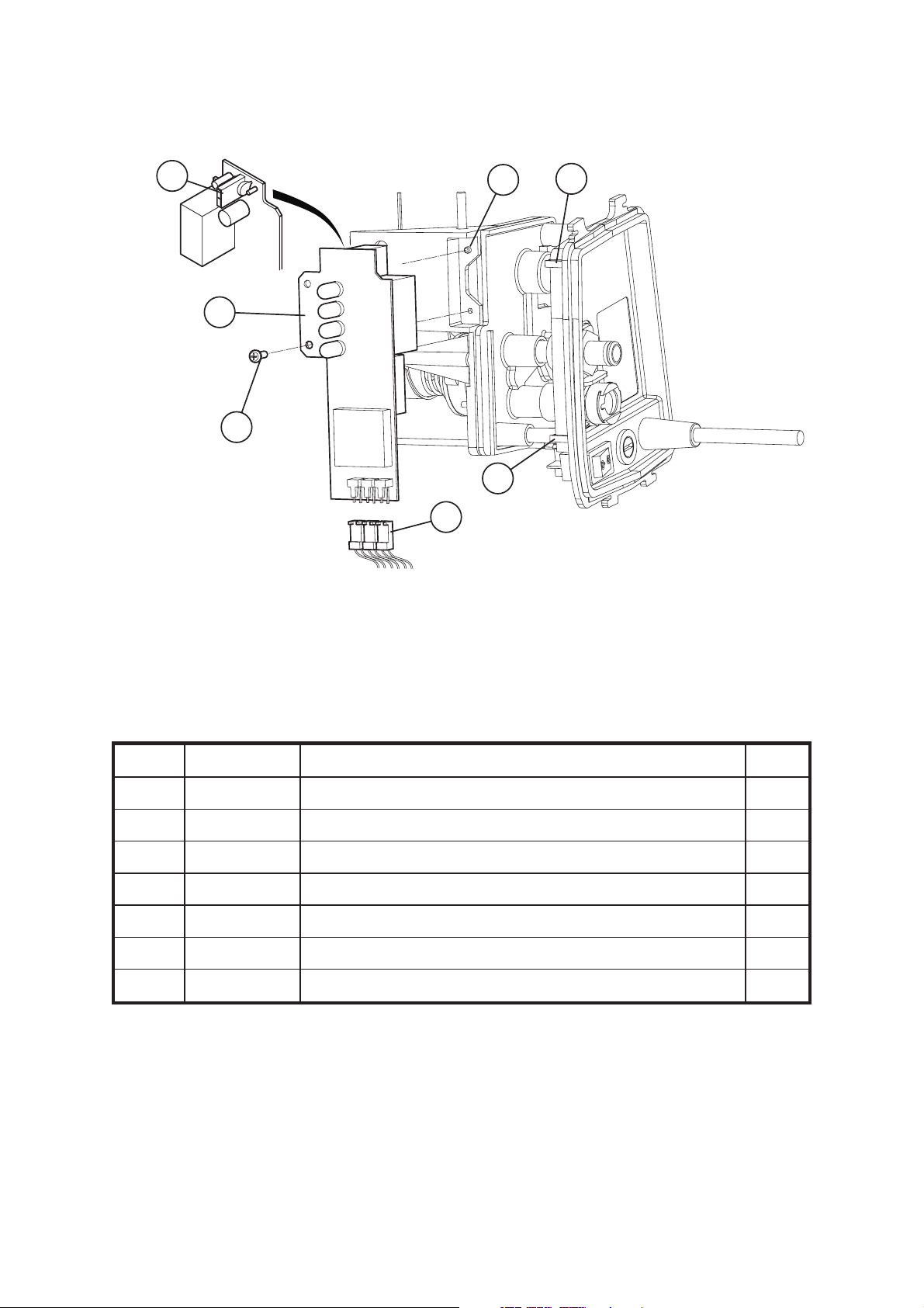
Figure 14 - Pressure Control Module
50
Chap 3 Issue 2
Page 26 SER0004 Nov 2001

Mini Pump Service Manual Pump Repair
Table 18 - Pressure Control Module Part List
Item Part Number Description Qty
10 500347 Terminal Block 5 way 1
20 BP196 Cable Tie 2
30 500362 Tube Sil ID 3/16” 135 mm ± 5 mm LG 1
40 FAS145 Screw 3 Dia.x8mmPozi Pan Head PT 1
50 FAS223 Screw 3 Dia. x 10 mm Pozi Pan Head PT 3
60 500315 Panel Side Colder 1
70 500328 Panel Side Push On 1
80 151309 Fixing Cap 1
29 Replacing the Pressure Control Module
29.1 Remove the pressure control knob as described in Page 3, Section 2.
29.2 Remove the rear case assembly as described in Page 5, Section 6.
29.3 Remove the compressor wires (Fig 14, Item 10) from the terminal block (terminals 3 and 4).
This also releases two switch wires.
29.4 Carefully cut the cables ties from the wiring loom as required (Fig 14, Item 20).
29.5 Remove the tube (Fig 14, Item 30) between the pressure control module and the ‘F’ connector.
29.6 Remove the module securing screw (Fig 14, Item 40) and the fixing cap (Fig 14, Item 80).
29.7 Carefully lift the module with the side panel attached from the pump case.
29.8 Disconnect the fuse wire from the terminal block (terminal 6) and disconnect the adjacent
switch wire (terminal 5) (Fig 14, Item 10).
29.9 Disconnect the mains/power lead wires from the terminal block (terminals L and N) (Fig 14,
Item 10).
29.10 Remove three screws (Fig 14, Item 50) and detach (pull off the pressure control module from
the side panel assembly (Fig 14, Item 70).
29.11 Replacement is the reversal of the above procedures. Refer to the wiring diagram (Chap. 4,
Fig 23 (electronic) or 24 (mechanical)) when reconnecting the wires to the terminal block.
Issue 2 Chap 3
Nov 2001 SER0004 Page 27
Pump Repair Mini Pump Service Manual
60
20
10
30
40
50
40
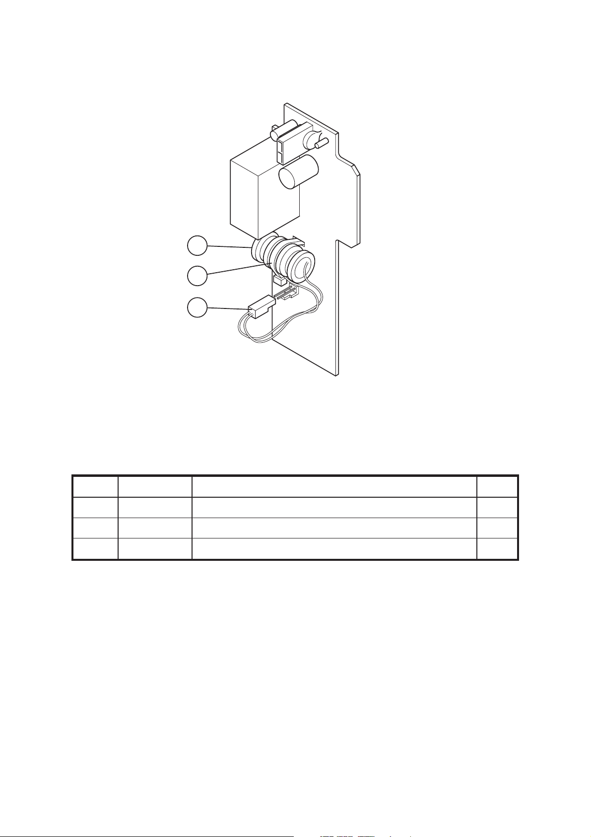
Figure 15 - Removing the Alarm Monitoring PCB
Table 19 - Removing the Alarm Monitoring PCB Part List
Item Part Number Description Qty
10 FAS083 Screw No. 6 x 5/16” Pozi Pan Head PT 1
20 500346 PCB Alarm Monitoring 230 V 1
500345 PCB Alarm Monitoring 100/120 V 1
30 N/A Signal Connectors REF
40 N/A Side Panel Slotted Mounts REF
50 N/A Lug REF
60 N/A PCB Power Wires Socket REF
Chap 3 Issue 2
Page 28 SER0004 Nov 2001

Mini Pump Service Manual Pump Repair
30 Replacing the Alarm Monitoring PCB
CAUTION : Electrostatic discharge can seriously damage the alarm monitoring PCB. Prior to
replacing or handling, adequate earth/grounding precautions must be taken.
Notes:1Itisnotnecessary to remove the side panel in order to replace the alarm monitoring PCB.
2 The alarm monitoring PCB is only applicable to electronic versions of the mini pump.
30.1 Remove the pressure control module as described in Page 27, Section 29.1 to 29.7.
30.2 Disconnect PCB power wires (Fig 15, Item 60) from PCB.
30.3 Disconnect the three signal connectors from the PCB (Fig 15, Item 30).
30.4 Remove the PCB securing screw (Fig 15, Item 10) and withdraw the PCB (Fig 15, Item 20).
30.5 Replacement is the reverse procedure to removal. Ensure that the PCB is seated in the two
slotted mounts of the side panel (Fig 15, Item 40) and the lug (Fig 15, Item 50) on the pressure
control module.
Issue 2 Chap 3
Nov 2001 SER0004 Page 29
Pump Repair Mini Pump Service Manual
10
20
30
Figure 16 - Replacing the Power Failure Alarm Battery
Table 20 - Battery (Power Failure Alarm) Part List
Item Part Number Description Qty
10 151457 Battery 1
20 N/A Cable Tie 1
30 N/A Battery Plug to PCB 1
Chap 3 Issue 2
Page 30 SER0004 Nov 2001

Mini Pump Service Manual Pump Repair
31 Changing the Battery
Caution : Electrostatic discharge can seriously damage the alarm monitoring PCB. Prior to
replacing or handling, adequate earth/grounding precautions must be taken.
Notes:1Itisnotnecessary to remove the side panel in order to change the battery.
2 The battery (power failure alarm) is only applicable to electronic versions of the mini pump.
31.1 Remove the PCB (Refer to Page 29, Section 30,).
31.2 Remove the battery plug (Fig 16, Item 30) from the PCB.
31.3 Cut and remove the cable tie (Fig 16, Item 20) and remove the battery (Fig 16, Item 10).
31.4 Replacement is the reverse procedure to removal.
Note : The cable tie must be renewed/replaced when changing the battery.
Issue 2 Chap 3
Nov 2001 SER0004 Page 31
Pump Repair Mini Pump Service Manual
30
10
30
ENS
THISSIE
RE
20
Figure 17 - Replacing the Neon Indicator Light
Table 21 - Neon Indicator Part List
Item Part Number Description Qty
10 FAS083 Screw No. 6 x 5/16” Pozi Pan Head PT 1
20 500324 Plate Neon Mounting 1
30 500373 Neon Assembly Red 230 V 1
500371 Neon Assembly Red 110 V
Chap 3 Issue 2
Page 32 SER0004 Nov 2001

Mini Pump Service Manual Pump Repair
32 Replacing the Neon Indicator Light
Note : The neon indicator light is only applicable to the mechanical versions of the pump. The
electronic version of the pump has two red indicators, a green indicator and a yellow indicator.
These are wired directly into the PCB and are replaced only by exchanging the complete PCB.
32.1 Disconnect the indicator lead from the terminal block (terminal 2) (Fig 14, Item 10).
32.2 Disconnect the indicator lead from the Micro switch (Fig 18, Item 10).
32.3 Release the screw (Fig 17, Item 20) attaching the neon mounting plate (Fig 17, Item 10) and
remove the neon (Fig 17, Item 30) and mounting plate assembly.
32.4 Note the orientation of the components, unclip the neon (Fig 17, Item 30) from the lens and
push the lens out of the mounting plate.
32.5 Replacement is the reverse procedure of the above. Ensure the correct orientation of
components. Connect the wires to the terminal block and the Micro switch in accordance with
the wiring diagram for the mechanical version of the pump unit (Chap. 4, Fig 25).
Issue 2 Chap 3
Nov 2001 SER0004 Page 33

Pump Repair Mini Pump Service Manual
10
20
30
L
40
6
N
5
1
4
2
3
L
N
1
2
6
5
4
3
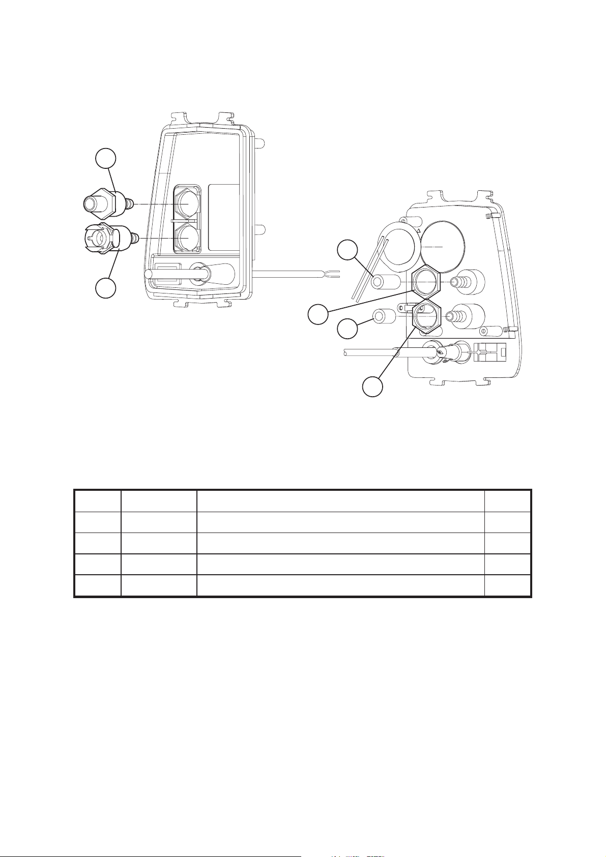
Figure 18 - Replacing the Micro switch and Terminal Block
Table 22 - Micro switch and Terminal Block Part List
Item Part Number Description Qty
10 500338 Micro switch Sub Min 230 V/0.1A 1
20 FAS224 Screw 2.2 Dia. x 14 mm Pozi Pan Head PT 2
30 500347 Terminal Block 5 Way 1
40 FAS225 Screw 3 Dia. x 16 mm Pozi Pan Head PT 2
Chap 3 Issue 2
Page 34 SER0004 Nov 2001

Mini Pump Service Manual Pump Repair
33 Replacing the Microswitch
Note : It is not necessary to remove the pressure control module from the pump case.
33.1 Pull off connectors from the Micro switch terminals 1 and 3 (Fig 18, Item 10).
33.2 Release two screws (Fig 18, Item 20) and remove the Micro switch from the pressure control
module.
33.3 Replacement is the reverse of the above procedure.
34 Replacing the Terminal Block
Note : It is not necessary to remove the pressure control module from the pump case.
34.1 Disconnect all wires from the terminal block (Fig 18, Item 30).
34.2 Release two securing screws (Fig 18, Item 40) and remove the terminal block from the
pressure control module.
34.3 Replacement is the reversal of the above procedure. Refer to the wiring diagram (Chap. 4,
Fig 24) when reconnecting the wires for the electronic version of the pump and wiring diagram
(Chap. 4, Fig 25) when reconnecting the wires for the mechanical version of the pump.
Issue 2 Chap 3
Nov 2001 SER0004 Page 35
Pump Repair Mini Pump Service Manual
90
70
60
20
50
10
30
40
80
(Aura Pumps Only)
100
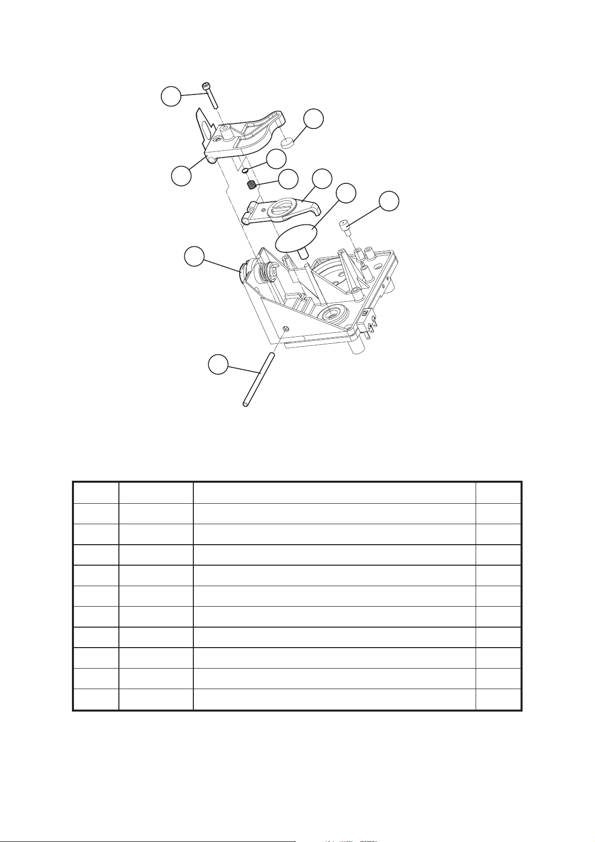
Figure 19 - Pressure Control Flaps, Air Bag, Control Knob Cam and Arbour
Table 23 - Pressure Control Flaps, Air Bag, Control Knob Cam and Arbour Part List
Item Part Number Description Qty
10 500304 Knob Control Arbour 1
20 500312 Upper Pressure Control Flap 1
30 500318 Pivot Pin, Pressure Control 1
40 500303 Lower Pressure Control Flap 1
50 500341 Spring 0,024” Diameter 1
60 151339 Pressure Control Disc 1
70 PRE022 Rubber Valve Disc 1
80 500103 Bag Pressure with Restrictor Assembly 1
90 500355 Screw M3 x16 mm Socket Cap Hd Black 1
100 403306 Restrictor (Aura Pumps Only) 1
Chap 3 Issue 2
Page 36 SER0004 Nov 2001

Mini Pump Service Manual Pump Repair
35 Replacing the Pressure Control Flaps and Air Bag
35.1 Turn the control knob arbour fully counter-clockwise (Fig 19, Item 10). Hold the upper pressure
control flap (Fig 19, Item 20) in position and withdraw the pivot pin (Fig 19, Item 30). Carefully
remove the upper flap and the lower flap (Fig.19, Item 40) together with the low pressure
operating spring and brass disc (Fig 19, Items 50 and 60).
35.2 Remove and discard the pressure control disc (Fig 19, Item 70) from the upper flap. Replace
with new item.
35.3 Remove and discard the air bag assembly (Fig 19, Item 80). Replace with a new item. Ensure
the air bag is secure by pushing in the centre and rotate it slightly to ensure it is seated.
35.4 Ensure that the low pressure adjustment screw (Fig 19, Item 90) is fully disengaged. Carefully
locate the brass disc (Fig 19, Item 60), boss uppermost in the rebate in the upper flap. Locate
the spring (Fig 19, Item 50) on the disc and position the lower flap (Fig 19, Item 40) against the
spring.
35.5 Refitting is the reverse of the above procedure. When refitting, hold the group of components
together and position them on the pressure control module. Insert the pivot pin (Fig 19, Item
30) to retain the flaps.
Issue 2 Chap 3
Nov 2001 SER0004 Page 37

Pump Repair Mini Pump Service Manual
10
A
B
60
A
NEW
NEW
50
OLD
OLD
B
30
40
20
Figure 20 - Control Knob Cam and Arbour
Table 24 - Control Knob Cam and Arbour Part List
Item Part Number Description Qty
10 FAS225 Control Adjustment Screw, 3 Dia x 16 mm Pozi Pan Head PT 1
20 500305 Knob Control Cam 1
30 500411 Cup Arbour Drive Spring 1
40 500339 Spring Comp 1.07 Diameter 1
50 500349 Pressure Assembly Module 1
60 500304 Knob Control Arbour 1
Chap 3 Issue 2
Page 38 SER0004 Nov 2001

Mini Pump Service Manual Pump Repair
36 Replacing the Pressure Control Assembly
Note:Itisnot necessary to remove the side panel assembly from the pressure control module.
36.1 Remove the pressure control module from the pump case as described in Section 29.
36.2 Remove the pressure control flaps as described in Section 35.
36.3 Release the control adjustment screw on the control knob arbour (Fig 20, Item 10).
36.4 Carefully remove the arbour, cam, spring cup and spring (Fig 20, Items 20, 30 and 40).
36.5 Renew/replace components with the same type.
Note : Early versions may have a nylon washer in lieu of the spring cup. Discard the washer and
replace with the cup.
36.6 Replacement is the reverse of the above procedure. Refit the pressure control flaps as
described in Section 35.
Note : The new control knob arbour will NOT fit the old pressure assembly module because of the
moulded wall on the old pressure assembly module. The old control knob abour will fit both.
Issue 2 Chap 3
Nov 2001 SER0004 Page 39

Pump Repair Mini Pump Service Manual
10
20
110
100
90
70
80
50
30
40
60
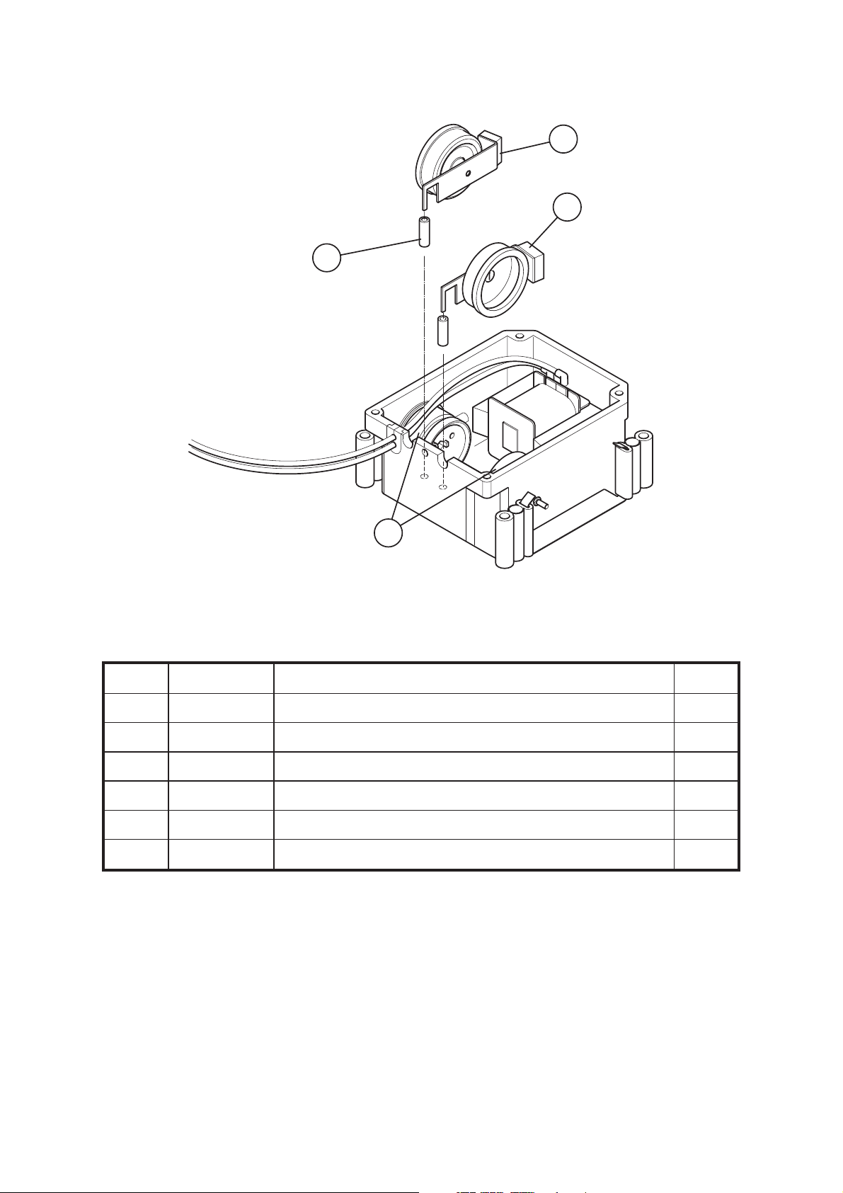
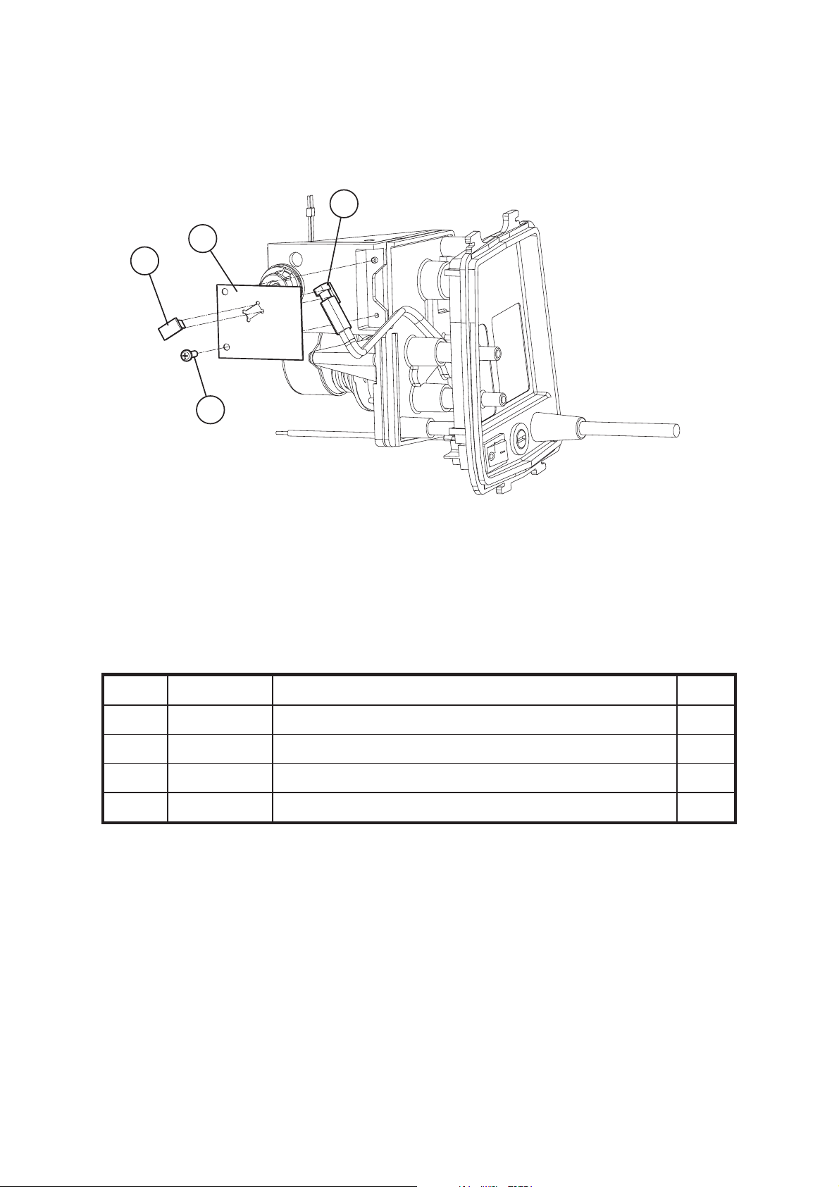
Figure 21 - Synchronous Motor (Gearbox), Rotor/Stator Assembly
Table 25 - Synchronous Motor (Gearbox), Rotor/Stator Assembly Part List
Item Part Number Description Qty
10 FAS223 Screw 3 Dia x 10 mm Pozi Pan Head 2
20 500097 Gearbox 240V and Ferrule Assembly 1
500098 Gearbox 120V and Ferrule Assembly 1
500099 Gearbox 100V and Ferrule Assembly 1
151409 Motor Gearbox 100V, 50 Hz, 1/10 RPM 1
30 500308 Rotor Module 1
40 500307 Stator Module 1
50 500332 Felt Rotor Silencer 1
Chap 3 Issue 2
Page 40 SER0004 Nov 2001

Mini Pump Service Manual Pump Repair
Table 25 - Synchronous Motor (Gearbox), Rotor/Stator Assembly Part List (continued)
Item Part Number Description Qty
60 500319 Stator Gasket 1
500418 Stator Gasket (Restricted) 1
70 500356 Rotor Drive Cup 1
80 500322 Pin Rotor Drive 1
90 500354 Washer Starlock O/D 21 mm 1
100 500358 Spring Comp 1.6 Diameter FL 22.36 1
110 TIM017 Oil Seal Cap 1
37 Replacing the Synchronous Motor (Gearbox), Rotor Stator Assembly
Note:Itisnot necessary to remove the side panel assembly from the pressure control module.
37.1 Remove the pressure control module from the pump case as described in Section 29.
37.2 Remove any relevant cable ties.
37.3 Identify the synchronous motor electrical lead from the terminal block (terminals 1 and 2) (Fig
18, Item 30). remove the relevant cable ties and release the synchronous motor electrical lead.
37.4 Remove the two screws securing the gearbox motor (Fig 21, Item 10).
37.5 Carefully remove the synchronous motor, rotor and stator (Fig 21, Items 20, 30 and 40) from
the pressure control module. Remove the felt rotor silencer (Fig 21, Item 50) from the rotor.
Remove the stator gasket (Fig 21, Item 60) from the pressure assembly module.
37.6 Depress the motor drive cup (Fig 21, Item 70) toward the motor and remove the drive shaft pin
(Fig 21, Item 80).
37.7 Carefully remove the rotor drive cup, star washer (Fig 21, Item 90), spring (Fig 21, Item 100)
and oil seal cap (Fig 21, Item 110) from the motor.
37.8 Replace any faulty parts with same type.
37.9 Discard the stator gasket and replace with a new one before reassembly.
37.10 Replacement is the reverse of the above procedure. Ensure that the stator is correctly located
in the key and cables are secured with relevant cable ties.
Issue 2 Chap 3
Nov 2001 SER0004 Page 41

Pump Repair Mini Pump Service Manual
BROWN
BROWN
1A
2A
4B
3B
ORANGE
10
50
40
20
30
Figure 22 - Replacement of the Side Panel On/Off Switch
Table 26 - Side Panel On/Off Switch, Mains/Power Lead and Fuses Part List
Item Part Number Description Qty
10 500351 Switch Mains/Power Rocker 230 V Black (All electronic pumps) 1
500343 Switch Mains/Power Rocker 230 V Green (Illuminated) 1
500359 Switch Mains/Power Rocker 110 V Green (Illuminated) 1
20 198315 Grommet 1
30 BP532 Cordset Standard Moulded UK (Cable) 1
CAS041 Mains/Power Cable - European “Shuko” Socket 1
BP087 Mains/Power Cable - USA 2 pin 1
CAS020 Mains/Power Cable - Japan 2 pin 1
BP171 Mains/Power Cable - Australia 1
40 500344 Fuse Holder 1
50 CAS011 Fuselink 20x5mm500mAQB 1
Chap 3 Issue 2
Page 42 SER0004 Nov 2001

Mini Pump Service Manual Pump Repair
38 Replacing the Side Panel Mains/Power On/Off Switch
38.1 Remove the pressure control module and remove the side panel as described in Section 29.
38.2 Pull off the electrical connections from the On/Off switch (Fig 22, Item 10).
38.3 Squeeze together the retaining flanges located on either side of the switch body and push the
switch through the side panel.
38.4 Replace the switch with same type. Ensure correct orientation of the switch (symbol nearest
the fuse). Ensure that the retaining flanges snap into position. Refer to the wiring diagram
(Chap. 4, Fig 23) when reconnecting the electrical wires for the electronic version of the pump
and (Chap. 4, Fig 24 ) when connecting the electrical wires for the mechanical version of the
pump.
39 Replacing the Side Panel Mains/Power Lead
39.1 Remove the pressure control module, and remove the side panel as described in Section 29.
39.2 Carefully withdraw the mains/power lead (Fig 22, Item 30) through the mains lead/power cord
grommet.
39.3 Carefully withdraw the mains/power lead grommet (Fig 22, Item 20) through the side panel.
39.4 Replace the lead with the same part number. Replacement is the reverse of the above
procedure. Ensure adequate cable length so that wires are not strained.
WARNING:
WHEN AN UNSERVICEABLE MAINS/POWER LEAD FITTED WITH A
NON-REWIREABLE PLUG IS REMOVED FROM THIS EQUIPMENT, THE
LEAD/CORD AND THE PLUG MUST BE DESTROYED AND DISPOSED OF
SAFELY. TO AVOID THE DANGER OF ELECTRIC SHOCK THE PLUG
MUST NEVER BE INSERTED IN ANY POWER OUTLET.
40 Replacing the Fuses
Note : The side panel assembly is supplied complete with fuse holder fitted. The fuse holder is not a
replaceable item.
40.1 To replace the pump fuse undo the fuse holder (Fig 22, Item 40) and remove the fuse (Fig 22,
Item 50). Replace with fuse of same type.
40.2 To replace the mains/power lead plug fuse in moulded plugs use a small bladed electrical
screwdriver and carefully lever off the fuse cover on the pin side of the plug. Replace with fuse
of same type.
Issue 2 Chap 3
Nov 2001 SER0004 Page 43
Pump Repair Mini Pump Service Manual
20
30
10
20Part
40
10Part
Figure 23 - Snap-lock Connectors
Table 27- Snap-lock Connectors
Item Part Number Description Qty
10 500350 Connector Panel, Female 1/4” Flow 1
20 504316 Connector Panel, Male 1/4” Flow 1
30 500361 Tube Sil Blue ID 6 OD 10 24 LG ± 1 1
40 500360 Tube Sil Blue ID 6 OD 10 15 LG ± 1 1
Chap 3 Issue 2
Page 44 SER0004 Nov 2001

Mini Pump Service Manual Pump Repair
41 Replacing the Snap-lock Connectors
Note : Older versions have a pump connectors moulded within the side panel and are not
replaceable.
41.1 Remove pressure control module with side panel (Refer to Section 29.1 to 29.7)
41.2 Refer to Fig 15, disconnect the three signal connectors (Fig 15, Item 30 ) and the power wires
from the PCB.
41.3 Remove screw (Fig 15, Item 10) and remove the PCB.
41.4 Undo locknut and withdraw connector through side panel with tube.
41.5 Remove tube from connector.
41.6 Replace with the same type. Replacement is the reverse of the above procedure. Ensure that
the snap lock release clip on the female (lower) connector is pointing toward the rear of the
case. Make sure the locknut is on the pressure module before the connector and tube is
inserted.
Issue 2 Chap 3
Nov 2001 SER0004 Page 45

Pump Repair Mini Pump Service Manual
42 Removing the Front Case
42.1 Remove the pressure control knob (Page 3, Section 2).
42.2 Disassemble the rear case (Page 5, Section 6).
42.3 Remove the screw and the fixing cap (Refer to Fig 14, Items 40 and 80) from the pressure
control module.
42.4 Remove the pressure control module, together with the side panel, and the compressor from
the front case (Fig 2, Item 40).
43 Installing the Front Case
43.1 For Aura, AlphaXcell, AlphaTrancell ALT01-09, fit the pin (Fig 2, Item 30) to the new front case.
Note : For Alpharelief, Alphabed, Alphacare and AlphaTrancell ALT10 pumps, the pin is not needed.
This allows 270° movement of the Pressure Control Knob.
43.2 Fit a front label to the front case (Refer to Table 28 for the correct label set).
43.3 Install the pressure control module, together with the side panel, and the compressor in the
front case.
43.4 Install the fixing cap and the screw (Refer to Fig 14, Items 80 and 40) to the pressure control
module.
43.5 Assemble the rear case (Page 5, Section 7).
43.6 Install the pressure control knob (Page 3, Section 3).
43.7 Fit rubber feet to the base of the front case (Fig 4, Item 50).
Chap 3 Issue 2
Page 46 SER0004 Nov 2001

Mini Pump Service Manual Pump Repair
44 Pump Label Sets
The following table gives the part numbers for the pump label sets:
Table 28 - Pump Label Sets
Part Number Description Qty
AlphaXcell
Series
500386 Label set UK - AlphaXcell (ALX01) 1
500387 Label set Germany - AlphaXcell (ALX02) 1
500388 Label set USA - AlphaXcell (ALX03) 1
500389 Label set Euro - AlphaXcell (ALX04) 1
500390 Label set France - AlphaXcell (ALX05) 1
500391 Label set Japan - AlphaXcell (ALX06) 1
500392 Label set Italy - AlphaXcell (ALX017) 1
500393 Label set Australia - AlphaXcell (ALX08) 1
500394 Label set Rest of the World - AlphaXcell (ALX09) 1
500395 Label set Holland - AlphaXcell (ALX10) 1
500472 Label set Rest of the World - AlphaXcell (ALX11) 1
AlphaBed
Series
500397 Label set UK - AlphaBed (ALB01) 1
500398 Label set Euro - AlphaBed (ALB04) 1
500441 Label set Poland - AlphaBed (ALB04 - PL) 1
500399 Label set Australia - AlphaBed (ALB08) 1
500400 Label set Rest of the World - AlphaBed (ALB09) 1
Alpha Trancell
Series
500412 Label set UK - Alpha Trancell (ALT01) 1
500396 Label set Germany - AlphaTrancell (ALT02) 1
500414 Label set Holland - Alpha Trancell (ALT10) 1
500440 Label set Poland - Alpha Trancell (ALT01-PL) 1
Issue 2 Chap 3
Nov 2001 SER0004 Page 47

Pump Repair Mini Pump Service Manual
Table 28 - Pump Label Sets (continued)
Part Number Description Qty
Alpha Relief
Series
500475 Label set UK - Alpha Relief (ALR01) 1
500478 Label set Germany - Alpha Relief (ALR02) 1
500470 Label set USA - Alpha Relief (ALR03) 1
500476 Label set Euro - Alpha Relief (ALR04) 1
AlphaCare
Series
500401 Label set USA - AlphaCare (ALC03) 1
500402 Label set Euro - AlphaCare (ALC04) 1
500473 Label set Japan - AlphaCare (ALC06) 1
Aura Series
500474 Label set UK - Aura (ALS01) 1
500479 Label set USA - Aura (ALS03) 1
500477 Label set Euro - Aura (ALS04) 1
Chap 3 Issue 2
Page 48 SER0004 Nov 2001

Mini Pump Service Manual Troubleshooting
CHAPTER 4
TROUBLESHOOTING
1 General
This section details some problems which may occur after a long period of use and the appropriate
procedures to correct them.
The Alpha Relief, Aura and AlphaXcell (electronic) pump units are fitted with a visual and audible
alarm for LOW PRESSURE and POWERFAIL alarm conditions. The alarm for the AlphaBed, Care
and Trancell (mechanical) pump units are limited to a visual red LOW PRESSURE (!) lamp indicator.
The alarm automatically resets when the operating pressure is regained. See Table 4 for details of
the each product’s visual indicators.
Table 29 gives a quick reference to common problems, possible causes and actions. Refer to the
table first when carrying out troubleshooting on a pump.
Table 29 - Troubleshooting
Problem Possible Cause Action
Mattress/Seat not
Inflating.
Applicable to all pumps.
Low pressure alarm.
Applicable to all pumps.
Wait indicator does not go
out not allowing the
system to pressurize.
Applicable to:
ALR 01-10
ALX 01-10
1. CPR not inserted (mattress only). Check CPR (See Mattress
Service Manual SER0005).
2. Tubes kinked. Check.
3. Pump not switched on. Check.
4. No pump output. Check. See ‘Pump not
operating’ below.
5. Tubes not correctly fitted. Check.
1. CPR not inserted (mattress only). Check CPR (See Mattress
Service Manual SER0005).
2. Tubes not correctly fitted. Check.
3. Leakage. Check (See Mattress
Service Manual SER0005).
1. CPR not inserted (mattress only). Check CPR (See Mattress
Service Manual SER0005).
2. Tubes not correctly fitted. Check.
3. Leakage. Check CPR (See Mattress
Service Manual SER0005).
Mains/Power Fail
indicators (audible and
visual) are active.
Applicable to:
ALR 01-10
ALX 01-10
ALS 01-10
Issue 2 Chap 4
Nov 2001 SER0004 Page 1
1. Mains/power failure has occurred. Check.
2. The mains/power lead has been
removed from the wall socket.
Check.

Troubleshooting Mini Pump Service Manual
Table 29 - Troubleshooting (continued)
Problem Possible Cause Action
Mains/Power Fail indicator
remains illuminated but
there is no audible alarm.
Applicable to:
ALR 01-10
ALX 01-10
ALS 01-10
Pump is very noisy and/or is
causing excessive vibration.
Applicable to all pumps.
Pump not operating
Applicable to all pumps.
There has been a mains/power
failure but power has been restored.
System is damaged or dirty. 1. Check compressor
1. Pump run switch not on. Switch on.
2. Plug not inserted correctly. Check.
3. Fuse blown. Replace the fuse (Refer to
Check if electrical plug is
correctly fitted and if pump is
running correctly.
mounts for wear
(Refer to Ch 3, Pg 13).
2. Check compressor is
not loose on its
mounting plate
(Refer to Ch 3, Pg 17).
3. Check the compressor
bellows are not split
(Refer to Ch 3, Pg 21).
Ch 3, Pg 43).
4. Loss of output pressure. Refer to Section 2 and 3
below.
All indicators/lights remain
illuminated on initial
switch-on.
Applicable to:
ALR 01-10
ALX 01-10
ALS 01-10
Internal fault Test the pump (Refer to
Ch 5).
Check PCB.
2 Low Pressure fault indicated (checks without dismantling the pump)
Check the following before dismantling the pump unit.
Perform the pressure, flow and low pressure alarm tests as specified in Chap. 5 (Testing). If the
results are satisfactory, the mattress is at fault.
Note : All testing must be done when pumps are warm, ie. they have been running with closed ports
for at least 1 hour.
Check:
2.1 All tubing connections on pump and mattress are securely fastened and snap locked into place.
2.2 Check that the rapid deflate stopper or CPR is fitted correctly (Refer to Mattress Service
Manual, SER0005).
Chap 4 Issue 2
Page 2 SER0004 Nov 2001

Mini Pump Service Manual Troubleshooting
2.3 If the alarm still indicates, visually inspect tubing and mattress cells for punctures or tears and
check they are fitted to the manifold correctly. Refer to the mattress service manual SER0005
for full details.
WARNING:
DANGER OF ELECTRIC SHOCK. DURING THE FOLLOWING TESTS, LIVE
TERMINALS AND CONDUCTORS MAY BE EXPOSED. EXERCISE EXTREME
CAUTION.
3 Loss of Output Pressure (checks by dismantling the pump)
If the low pressure alarm operates when both pump outlets are blocked or the pump does not pass
the flow test in Chapter 5 (Testing), the pump unit internal compressor should be tested as follows:
3.1 Remove the rear case (Refer to Chap 3, Page 5).
3.2 Disconnect the white pneumatic tube from the compressor F-Tube connector.
3.3 Connect the pressure gauge to the compressor F-Tube connector and switch the pump unit on.
The pressure reading should be at least 100 mmHg.
3.4 If the pressure does not reach 100 mmHg, the compressor is at fault. Either replace the
compressor or remove the compressor lid, remove the silencer bag from the valve bodies and
connect the pressure gauge to each valve body in turn. The pressure should be approximately
100 mmHg in each case. (Refer to Chap 3, Section 22).
3.5 If the required pressure cannot be reached then the bellows/armature assemblies and valve
bodies must be replaced (Refer to Chap 3, Section 23). If the required pressure is obtained
then the silencer bag must be replaced. (Refer to Chap 3, Section 22).
Note : The flow/pressure performance of a compressor may be altered by heating the new bellows
and adjusting the ‘E’ stack gap.
3.6 If the compressor is operating correctly but the correct pressure cannot be obtained at the
pump outlet then the rotor/stator, pressure control module and snap-lock connectors must be
checked. Reassemble the compressor and attach pressure rig to pump outlet again.
3.7 Remove the gearbox and rotor/stator, clean all dust off rotor/stator and reassemble with new
gasket. If rotor/stator is chipped or damaged, replace components (Refer to Chap 3, Section
37). If this does not correct the problem, check the pressure control.
3.8 Push on the pressure control flap (Fig 19, Item 20) to press the seal (Fig 19, Item 70) against
the valve seat. Check the pressure control bag inflates fully and pushes on the flap, if not, the
bag could be split - check and replace as necessary.
3.9 If the snap-lock connectors or tubing show signs of damage, replace. If there is still a problem,
re-check in the following order:
•
compressor
•
rotor/stator assembly
•
pressure control assembly
•
connections
If pressure/flow still cannot be achieved, return pump to Service department.
Issue 2 Chap 4
Nov 2001 SER0004 Page 3

Troubleshooting Mini Pump Service Manual
4 Low Pressure Alarm Fault
If the low pressure alarm does not function correctly after recalibration as described in Chap. 5
(Testing), check:
4.1 The electrical connections and leads between the low pressure micro-switch and the printed
circuit board.
4.2 Check that switch is operating and n/o terminals (1-3) are in use.
4.3 Check free movement of lower flap.
4.4 Check low pressure switching point with an external pressure meter.
4.5 Check the pressure control module for leaks.
4.6 Check the location and orientation of low pressure spring and disc by removing upper and
lower flaps.
5 Air Not Alternating (continuous pressure fault)
Should the cells of the mattress not inflate and deflate during a 10-minute cycle, then the timer motor
may be defective (not rotating).
5.1 Check the timer motor electrical connections for security and integrity. If all are sound and the
timer motor still does not rotate, then the timer motor must be replaced.
Notes : The timer motor is a sealed unit and cannot be repaired.
When replacing the timer motor it is advisable to replace the stator gasket at the same
time. Refer to Chap. 3 (Pump Repair).
6 Loss of Electrical Power
Power loss can be due to any of the following:
6.1 No electricity supply at wall socket.
6.2 Faulty wall socket.
6.3 Damaged plug or mains/power cable.
6.4 Defective fuse link in pump or plug.
6.5 Damaged internal wiring.
6.6 Loose connections at the terminal block, micro-switch or PCB.
6.7 Faulty PCB component.
Chap 4 Issue 2
Page 4 SER0004 Nov 2001

Mini Pump Service Manual Troubleshooting
7 Circuit Diagrams
The circuit diagram for the electronic models is given in Fig 24. The circuit diagram for mechanical
models is given in Fig 25. Check for the above faults against the relevant circuit and repair as
appropriate.
Mains/Power
Lead
Live
Neutral
L
N
Gearbox
Terminal Block
L
6
5
N
1
4
N
L
N
2
3
L
L
N
Compressor
Fuse
Mains/Power
Switch
2A
1A
1A 3B
2A 4B
4B
3B
1
3
2
1
Microswitch
Sounder
3
PCB
L
N
Figure 24 - Circuit diagram for Alpha Relief, Aura and AlphaXcell (Electronic) Mini Pumps
Issue 2 Chap 4
Nov 2001 SER0004 Page 5
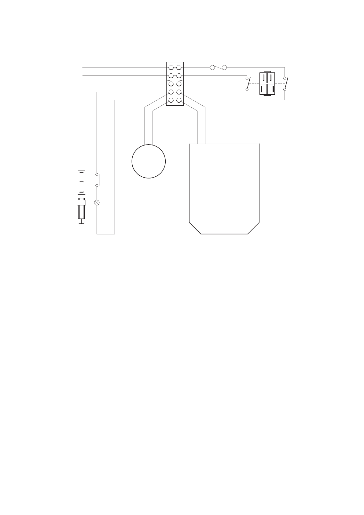
Troubleshooting Mini Pump Service Manual
Mains/Power
Lead
Microswitch
Live
Neutral
1
1
2
3
3
Neon
Terminal Block
Gearbox
L
6
N
5
1
4
N
L
N
3
2
L
Fuse Mains/Power Switch
4B
3B
LL
NN
2A4B
2A
1A
1A3B
Compressor
Figure 25 - Circuit diagram for AlphaXcell, AlphaBed, AlphaCare and Alpha TranCell
(Mechanical) Mini Pumps
Chap 4 Issue 2
Page 6 SER0004 Nov 2001

Mini Pump Service Manual Testing
CHAPTER 5
TESTING
1 Pump Flow, Pressure and Function Test
This procedure must be carried out after a service or major repair of a pump. To test/calibrate the
pump unit correctly, the following equipment or equivalent is required:
Table 30 - Pump Flow, Pressure and Function Test Equipment
Equipment Part Number
Typical Test Kit (including):- PRE 060
Digital Manometer (pressure gauge) 0-199 mmHg,
resolution 0.1, accuracy ± 0.2% of range.
Flowmeter 0-10 litre/minute, resolution 0.2, accuracy ± 2%
of measured value.
Battery, 9V Lantern
Male Connector BP431
Female Connector BP432
Note : All test equipment must be calibrated to national or international standards.
Flow and Pressure Checks
1.1 Connect the flowmeter, via a valve, to whichever outlet is working. Connect the pressure
gauge to measure the pressure at the outlet.
1.2 Open the valve fully. The free flow rate should not be less than specified in Table 31.
Table 31 - Minimum Flow Rates
AlphaBed
AlphaCare
Alpha Trancell
Alpha Relief
Aura
AlphaXcell
Pump
Airflow at
20 mmHg (ltr/min)
6
6
6
6
3.25
6
Airflow at
50 mmHg (ltr/min)
3
3
3
3
2.25
3
1.3 Close the valve and operate the pressure control knob on the pump from minimum to maximum
setting. The pressure indicated on the gauge (in mmHg) should be as specified in Table 31.
Issue 2 Chap 5
Nov 2001 SER0004 Page 1

Testing Mini Pump Service Manual
PRESSURE
ADJUSTMENT
SCREW
MINI PUMP
Stop Pin (If fitted)
DAMPER
(FOR EVEN FLOW)
MANOMETER
(mmHg)
9V
BATTERY
FLOW METER
Figure 26 - Typical Test Rig setup for Mini Pumps
Chap 5 Issue 2
Page 2 SER0004 Nov 2001

Mini Pump Service Manual Testing
Table 32 - Pressure Range
Pump Min. (mmHg) Max. (mmHg)
AlphaBed
AlphaCare
Alpha Trancell
ALT01-09
ALT10
Alpha Relief
Aura
AlphaXcell
If the pressure readings are incorrect then calibrate the pressure control as described below.
Calibration
1.4 If the pressure readings are incorrect then calibrate the pressure control as follows:
1.4.1 Turn the pressure control knob to the minimum setting.
1.4.2 Using a small, flat bladed screwdriver, carefully remove the pressure control knob. Be
careful not to move the arbour.
1.4.3 Rotate the screw in the centre of the pressure control arbour (counter-clockwise to
increase) until the indicated pressure is as specified in Table 33.
30±5
30±5
30±5
30±5
22±2
85±2
22±2
90±10
90±10
73±8
90±10
82±10
< 110
65±8
Note : Ensure that the pressure control arbour does not move.
Table 33 - Indicated Pressure
Pump Indicated Pressure
AlphaBed
AlphaCare
Alpha Trancell
Alpha Relief
Aura
AlphaXcell
1.4.4 Carefully replace the pressure control knob, ensuring that the control knob rotation is
limited between the minimum setting and the stop pin (if fitted).
1.4.5 Check the indicated pressure at minimum and maximum settings (Refer to Table 32)
and readjust if necessary.
1.4.6 Variation between the ports is to be no greater than 4 mmHg.
1.4.7 Attach the flow meter tube to whichever outlet is the duty port and check the free flow
again. The flow readings should be as specified in Table 31. Variation between the
ports is to be no greater than 1 litre/minute.
30 mmHg
30 mmHg
30 mmHg
22 mmHg
55 mmHg
22 mmHg
Set at dead
centre value
Issue 2 Chap 5
Nov 2001 SER0004 Page 3

Testing Mini Pump Service Manual
Low Pressure Indicator Test (Mechanical Units Only)
1.5 With the test equipment set up as in Section 1.1, set the pressure control knob in the mid
position and use the flowmeter valve to adjust the pressure slowly up and down.
1.6 Observe the LOW PRESSURE warning light to indicate the operation of the Micro switch.
1.7 The micro switch should activate at or before the pressure reaches 5 mmHg descending and
deactivate at or before the pressure reaches 20 mmHg ascending.
Low Pressure Indicator Test (Electronic units only)
WARNING
DANGER OF ELECTRIC SHOCK. DURING THE FOLLOWING TESTS, LIVE
TERMINALS AND CONDUCTORS MAY BE EXPOSED. EXERCISE EXTREME
CAUTION.
Note: Pump units fitted with an alarm monitoring PCB should have the low pressure alarm
settings tested within 60 seconds of switching the pump on.
1.8 Remove the rear case assembly (Refer to Chap 3, Section 6).
1.8.1 Fit snap-lock connectors to both outlet ports. Connect the pressure gauge and a
bleed valve to the duty port.
1.8.2 Connect a buzzer or LED to the microswitch terminals to indicate microswitch
operation (see Chap 4, Fig 24 for microswitch terminal connections).
1.8.3 Ensure that the bleed valve is fully closed, Ensure that the low pressure adjustment
screw (on the upper flap) is fully disengaged. Turn the arbour clockwise and
counter-clockwise over the full range three or four times. Leave it in the fully
counter-clockwise position.
1.8.4 Turn the pressure control knob until the indicated pressure is 50 mmHg (maximum
setting for Aura models only).
1.8.5 Open the bleed valve to induce a leak, until the pressure is 10 mmHg (60 mmHg for
Aura models only).
1.8.6 The microswitch should activate before the pressure reaches X mmHg descending
and deactivate before the pressure reaches Y mmHg ascending, as specified in
Table 34.
1.8.7 Set the low pressure adjustment screw so that the microswitch activates at this set
level. Do this very slowly. Adjust the pressure up and down by means of the bleed
valve and verify that the microswitch goes on and off accordingly.
1.8.8 Replace the rear cover (Refer to Chap 3, Section 7).
Chap 5 Issue 2
Page 4 SER0004 Nov 2001

Mini Pump Service Manual Testing
Table 34 - Descending and Ascending Pressures
Pump Pressure X Pressure Y
AlphaBed
AlphaCare
Alpha Trancell
Alpha Relief
Aura
AlphaXcell
5 mmHg
5 mmHg
5 mmHg
5 mmHg
50 mmHg
5 mmHg
2 Electrical Testing
To test and calibrate the pump unit correctly, the following equipment is required:
Table 35 - Electrical Test Equipment
Equipment
Insulation resistance tester (Megger) 500 Vdc
Portable appliance tester
Multimeter/Continuity tester
Dielectric strength tester (Flash tester) 3.0 kVac with current limit
17 mmHg
17 mmHg
17 mmHg
17 mmHg
82 mmHg
17 mmHg
Electrical Safety Checks – Class ll
There are several electrical safety checks that must be carried out after breakdown repairs, rental
re-checks and servicing. Where alternatives are given, the test will depend upon the available
equipment. The tests are as follows:
•
Insulation Resistance Test (Megger Test) or
•
Dielectric Strength (Flash Test)
Insulation Resistance Test
This test checks the integrity of the appliance’s insulation.
For all appliances, this test is applied between the connected Live and Neutral wires and the
appliance’s metal compressor assembly box.
Specification: 500 Vdc is applied to the insulation and the measured resistance must be greater
than 2 MW. This test can be conducted by using a Portable Appliance Tester. Also check the
continuity of the mains cable.
Dielectric Strength Test (Flash Test)
This test shows the response of the insulation to high ac-voltage stress, to the effects of the
capacitive current and gives an early warning of any electrical problems developing in the appliance.
Leakage Circuit Test (USA)
Measure the risk currents in accordance with the ANSI-AAMI ESI-1993 Standard (American National
Standard Safe Current Limits for Electromedical Apparatus) or as specified in UL 2601-1.
Issue 2 Chap 5
Nov 2001 SER0004 Page 5

Testing Mini Pump Service Manual
WARNINGS:
DANGER OF ELECTRIC SHOCK. DO NOT TOUCH ANY EXPOSED PARTS
WHILE CONDUCTING THIS TEST. DO NOT TOUCH ANY PART OF YOUR
BODY WITH THE CONTACTS OF THE PROBES.
THIS EQUIPMENT SHOULD NOT BE USED IF YOU HAVE A HEARING AID
OR PACEMAKER FITTED, DUE TO THE POSSIBILITY OF
ELECTROMAGNETIC DISTURBANCE.
Specification: 3.0 kVac is applied between the connected Live and Neutral wires and the appliance’s
metal compressor assembly box. No breakdown should occur.
Note : The voltage levels used for this test, may stress and weaken the insulation. This test, is
therefore not recommended as a routine test. It should only be used after a major
assembly/disassembly has been completed.
3 PCB Functional Tests (Electrical Units Only)
Tests must be carried out using a 220-240 V, 50 Hz power supply.
Test Setup and Initial Switch On
3.1 Install the mating parts of the snap-lock connectors on the pump outlets so that both outlets are
open to atmosphere. Set the pressure control knob fully counterclockwise.
3.2 Connect the mains/power cable to a suitable power socket outlet and then set the run/standby
switch to ‘run’. All four indicator lights should illuminate and the audible alarm should sound for
about 3 seconds. The green ON indicator, the amber WAIT indicator and the LOW
PRESSURE indicator will remain on. The POWER FAIL indicator light should extinguish.
Power Fail Alarm Check
3.3 With the pump operating, disconnect the power supply at the power socket outlet then
reconnect it after 4 seconds. Verify that no alarms are given and normal operation is resumed.
3.4 Again disconnect the power supply at the power socket outlet. Verify that, after 5 seconds, the
red POWER FAIL indicator flashes in conjunction with the audible alarm. The WAIT indicator
should go off when the POWER FAIL alarm indicator flashes. Reconnect the power supply.
Verify that the POWER FAIL indicator is extinguished.
3.5 Operate the run/standby switch to ‘standby’ and verify that all indicators are off. After 5
seconds, operate the switch back to ‘run’. Verify that all alarm indications are cleared and
normal operation is resumed. Operate the run/standby switch to ‘standby’.
Low Pressure Alarm Check
3.6 Use suitable sealing caps to close the ports. Operate the run/standby switch to ‘run’. Verify
that, after 1 minute, the WAIT indicator is extinguished.
3.7 Open both ports to atmosphere. Verify that, after 4 minutes and 45 seconds, the red LOW
PRESSURE indicator flashes in conjunction with the audible alarm.
3.8 Operate the run/standby switch to ‘standby’ and back to ‘run’. Verify that all alarm indications
are cleared and normal operation is resumed.
Chap 5 Issue 2
Page 6 SER0004 Nov 2001

Mini Pump Service Manual Testing
4 Functional Tests (Mechanical Units Only)
Tests must be carried out using a 220-240 V, 50 Hz power supply.
Test Setup and Initial Switch On
4.1 Set the pressure control knob fully counter-clockwise and ensure that both outlet ports are open
to atmosphere.
4.2 Connect the mains/power cable to a suitable power socket outlet and then set the on/off switch
to ‘on’ ( ). Verify that the green indicator in the switch is illuminated. Verify that the red LOW
PRESSURE indicator is illuminated. Use the fingers to close both outlet ports and verify that
the LOW PRESSURE indicator goes off.
Issue 2 Chap 5
Nov 2001 SER0004 Page 7

Testing Mini Pump Service Manual
Chap 5 Issue 2
Page 8 SER0004 Nov 2001

Mini Pump Service Manual Technical specification
CHAPTER 6
TECHNICAL SPECIFICATION
Pump Models
The pump models covered in this series are:-
Alpha Relief
•
Aura
•
AlphaXcell (Electronic)
•
AlphaXcell (Mechanical)
•
AlphaBed
•
AlphaCare
•
Alpha Trancell
•
Notes : Each model has a three letter code. For example, the Alpha Relief pump has the code ALR.
Following the three letter code is a two digit code representing customer country’s power
supply system. For example, the Alpha Relief pump is available to countries 01, 02, 03 and
04 (UK, Germany, USA and Europe-general respectively).
A complete breakdown of the pump model three letter codes and two digit codes is given
in Chap. 1, Tables 1 and 2.
Size
All pumps are 248 x 160 x 116 mm (9.8 x 6.3 x 4.6 inches).
Weight
All pump models are 2.75 kg (6 lb).
Pressure Ranges
Model Min (mmHg) Max (mmHg)
Alpha Relief 22 ± 2 82 ± 10
Aura 85 ± 2 <110
AlphaXcell 22 ± 2 65 ± 8
AlphaBed 30 ± 5 90 ± 10
AlphaCare 30 ± 5 90 ± 10
Alpha Trancell
ALT01-09
30±5 73±8
Alpha Trancell
ALT10
Issue 2 Chap 6
Nov 2001 SER0004 Page 1
30±5 90±10

Technical specification Mini Pump Service Manual
Cycle Time
The cycle time for all pump models is 10 minutes.
Rated Voltages
The voltage ratings for each of the customer (two digit) codes is given in Chap. 1, Table 2.
Rated Frequency
The mains/power frequency ratings for each of the customer (two digit) codes is given in Chap. 1,
Table 2.
Rated Input Power
The rated input power for all pump models is 14 VA.
Running Time
All pump models are designed for continuous consumption.
Test Standards
All pumps are tested to:
Europe En 60601-1
®
USA UL 2601-1 (Classified by Underwriters Laboratories Inc.
) with respect to electric
shock, fire and mechanical hazards only in accordance with UL 2601-1.
®
Canada CSA C22.2 No. 601-1 (Classified by Underwriters Laboratories Inc.
) with respect
to electric shock, fire and mechanical and other hazards only in accordance with
CAN/CSA C22.2 No. 601.1.
For the AlphaBed, AlphaCare and Alpha Trancell pumps, standards BS 5724 (part 1) 1989 and
VDE 0750: Teill also apply.
Protection Class
The protection class for all pump models is Class ll, type BF. The pumps are not protected against
the ingress of water.
Indicator Lights
The Alpha Relief, Aura and AlphaXcell (electronic) have four indicator lights:
Power On
Wait (except Aura)
Low Pressure
Power Fail
The AlphaXcell (mechanical), AlphaBed, AlphaCare and Alpha Trancell have one indicator light:
Low Pressure
Chap 6 Issue 2
Page 2 SER0004 Nov 2001

Mini Pump Service Manual Technical specification
Environmental Conditions
Operating conditions for all models:
Temperature range: +10° C to +40° C
Relative humidity: 30% to 75%
Atmospheric pressure: 700 hPa to 1060 hPa
Storage conditions for all pump models:
Temperature range: -40° C to +70° C
Relative humidity: 10% to 100% (non-condensing)
Atmospheric pressure: 500 hPa to 1060 hPa
Disposal: All units must be disposed of in accordance with local environmental regulations.
Issue 2 Chap 6
Nov 2001 SER0004 Page 3

Technical specification Mini Pump Service Manual
Chap 6 Issue 2
Page 4 SER0004 Nov 2001

Mini Pump Service Manual Parts list
CHAPTER 7
PARTS LIST
Part Number Description Fig-Item Qty
Front and Rear Case
500316 Front Case 2 - 40 1
500318 Pin (if fitted) 2 - 30 1
500484 Control Knob (MK2) 2 - 10 1
500304 Knob Arbour 2 - 20 1
500317 Rear Case 3 - 30 1
500340 Felt Filter 3 - 10 1
500327 Filter Plate 3 - 20 1
FAS223 Pan Head Screw PT 3 Dia x 10 Pozi 3 - 40 1
FAS225 Pan Head Screw PT 3 Dia. x 16 Pozi 3 - 50 4
500495 Bed Hook (New Style) 4 - 10 1
500496 Hook Plate (Left Hand) 4 - 20 1
500497 Hook Plate (Right Hand) 4 - 30 1
FAS223 Pan Head screw PT 3 Dia. x 10 4 - 40 8
500381 Rubber foot 4 - 50 8
Label Sets (See Chap 3, Page 47, Table 28)
Compressor Assembly
502003 Compressor Assy 230V 50Hz 11K/T 6 - 10
10-10
502002 Compressor Assy 110V 60Hz 5K/T (USA) 6 - 10
10-10
502007 Compressor Assy 100V 50/60Hz 4.5K/T (Japan) 6 - 10
10-10
502054 • Bellows Armature Assembly Left-Hand 230V 50Hz 11 - 10 1
1
1
1
BP215 Bellows Armature Assembly Left-Hand 110V 60Hz 1
502053 • Bellows Armature Assembly Right-Hand 230V 50Hz 11 - 20 1
BP214 Bellows Armature Assembly Right-Hand 110V 60Hz 1
BP043 • Armature Pivot 11 - 30 2
BP554 • Valve Body Assy, Blue 11 - 40
12-10
BP351 •• Valve Body 12 - 20 1
Issue 2 Chap 7
Nov 2001 SER0004 Page 1
2

Parts list Mini Pump Service Manual
Part Number Description Fig-Item Qty
FAS027 •• Screw, Hex Head 4BA x 3/4 12 - 30 1
FAS013 •• 4BA Full Nut 12 - 40 1
BP039 •• Valve Body Washer 12 - 50 2
BP037 •• Valve Flap 12 - 60 2
BP038 •• Valve Flap Securing Pad 12 - 70 2
BP028 •‘E’ Stack 13 - 10 1
FAS048 • Pan Head Screw M3 x 25 mm Pozi 13 - 20 2
FAS002 • Washer - 6BA Anti-Vib. 13 - 30 2
502050 • Coil Assembly 230V 50Hz (black/white leads) 13 - 40 1
502062 Coil Assembly 110V 60Hz (grey leads) 1
BP275 Coil Assembly 100V 50/60Hz (blue leads) 1
165303 • Grommet 13 - 50 1
502304 • Compressor Case 13 - 60 1
502301 • Compressor Lid 10 - 20 1
BP032 • Compressor Gasket 10 - 40 1
502055 • Silencer Bag 10 - 50 1
500320 ‘F’ Tube Connector 6 - 20
10-60
500410 Filter Retaining Clip 6 - 30 1
500417 Inlet Filter 6 - 40 1
500124 Compressor Mounting Bracket (New style) 7 - 10 1
500416 AV Mount (New style) 7 - 20 4
198375 AV Mount (Old style) 8 - 20 4
165310 Upper Bump Stop 9 - 10 1
165310 Lower Bump Stop 9 - 20 1
FAS160 Washer M4 Plain 9 - 40 2
1
FAS051 Screw Pan Head Pozi M4x6mm 9-50 2
FAS095 Screw Pan Head Pozi M4 x 10 mm 9 - 60 3
FAS054 Screw Countersunk Pozi M4 x 12 mm 10 - 30 4
Pressure Control Module
500347 Terminal Block 5 way 14 - 10
1
18-30
Chap 7 Issue 2
Page 2 SER0004 Nov 2001

Mini Pump Service Manual Parts list
Part Number Description Fig-Item Qty
BP196 Cable Tie 14 - 20 2
500362 Tube Sil ID 3/16” 135mm±5mmLG 14-30 1
FAS145 Screw 3 Dia.x8mmPozi Pan Head PT 14 - 40 1
FAS223 Screw 3 Dia. x 10 mm Pozi Pan Head PT 14 - 50 3
500315 Panel Side Colder 14 - 60 1
500328 Panel Side Push On 14 - 70 1
151309 Fixing Cap 14 - 80 1
500338 Micro switch Sub Min 230 V/0.1A 18 - 10 1
FAS224 Screw 2.2 Dia. x 14 mm Pozi Pan Head PT 18 - 20 2
500347 Terminal Block 5 Way 18 - 30 1
FAS225 Screw 3 Dia. x 16 mm Pozi Pan Head PT 18 - 40 2
500304 Knob Control Arbour 19 - 10
20-60
500312 Upper Pressure Control Flap 19 - 20 1
500318 Pivot Pin, Pressure Control 19 - 30 1
550303 Lower Pressure Control Flap 19 - 40 1
500341 Spring 0,024” Diameter 19 - 50 1
151339 Pressure Control Disc 19 - 60 1
PRE022 Rubber Valve Disc 19 - 70 1
500103 Bag Pressure with Restrictor Assembly 19 - 80 1
500355 Screw M3 x16 mm Socket Cap Hd Black 19 - 90 1
403306 Restrictor (Aura Pumps Only) 19 - 100 1
FAS225 Control Adjustment Screw, 3 Dia x 16 mm Pozi Pan Head
20-10 1
PT
500305 Knob Control Cam 20 - 20 1
500411 Cup Arbour Drive Spring 20 - 30 1
1
500339 Spring Comp 1.07 Diameter 20 - 40 1
500349 Pressure Assembly Module 20 - 50 1
FAS223 Screw 3 Dia x 10 mm Pozi Pan Head 21 - 10 2
500097 Gearbox 240V and Ferrule Assembly 21 - 20 1
500098 Gearbox 120V and Ferrule Assembly 1
500099 Gearbox 100V and Ferrule Assembly 1
151409 Motor Gearbox 100V, 50 Hz, 1/10 RPM 1
Issue 2 Chap 7
Nov 2001 SER0004 Page 3

Parts list Mini Pump Service Manual
Part Number Description Fig-Item Qty
500308 Rotor Module 21 - 30 1
500307 Stator Module 21 - 40 1
500332 Felt Rotor Silencer 21 - 50 1
500319 Stator Gasket 21 - 60 1
500418 Stator Gasket (Restricted) 1
500356 Rotor Drive Cup 21- 70 1
500322 Pin Rotor Drive 21- 80 1
500354 Washer Starlock O/D 21 mm 21- 90 1
500358 Spring Comp 1.6 Diameter FL 22.36 21- 100 1
TIM017 Oil Seal Cap 21- 110 1
PCB (Electronic versions only)
500346 PCB Alarm Monitoring 230 V 15 - 20 1
500345 PCB Alarm Monitoring 100/120 V 1
151457 • Battery 16 - 10 1
FAS083 Screw No. 6 x 5/16” Pozi Pan Head PT 15 - 10 1
Neon Indicator (Mechanical versions only)
500324 Plate Neon Mounting 17 - 20 1
500373 Neon Assembly Red 230 V 17 - 30 1
500371 Neon Assembly Red 110 V
FAS083 Screw No. 6 x 5/16” Pozi Pan Head PT 17 - 10 1
Mains/Power Switch and Supply
500351 Switch Mains/Power Rocker 230 V Black (All electronic
22-10 1
pumps)
500343 Switch Mains/Power Rocker 230 V Green (Illuminated) 1
500359 Switch Mains/Power Rocker 110 V Green (Illuminated) 1
198315 Grommet 22 - 20 1
BP532 Cordset Standard Moulded UK (Cable) 22 - 30 1
CAS041 Mains/Power Cable - European “Shuko” Socket 1
BP087 Mains/Power Cable - USA 2 pin 1
CAS020 Mains/Power Cable - Japan 2 pin 1
Chap 7 Issue 2
Page 4 SER0004 Nov 2001

Mini Pump Service Manual Parts list
Part Number Description Fig-Item Qty
BP171 Mains/Power Cable - Australia 1
500344 Fuse Holder 22 - 40 1
CAS011 Fuselink 20x5mm500mAQB 22-50 1
Snap-lock Connectors
500350 Connector Panel, Female 1/4” Flow 23 - 10 1
504316 Connector Panel, Male 1/4” Flow 23 - 20 1
500361 Tube Sil Blue ID 6 OD 10 24 LG ± 1 23 - 30 1
500360 Tube Sil Blue ID 6 OD 10 15 LG ± 1 23 - 40 1
Service Kit
500135 Service Kit (240v only)
BP043 • Armature Pivot 2
502055 • Silencer Bag 1
502053 • Bellows Armature Assembly Right-Hand 230v 50Hz 1
502054 • Bellows Armature Assembly Left-Hand 230v 50Hz 1
500340 • Felt Filter (Case) 1
500417 • Inlet Filter (Compressor) 1
Issue 2 Chap 7
Nov 2001 SER0004 Page 5

Parts list Mini Pump Service Manual
Chap 7 Issue 2
Page 6 SER0004 Nov 2001

Mini Pump Service Manual Service Contact Details
CHAPTER 8
SERVICE CONTACT DETAILS
Africa
Huntleigh Africa (Pty) Limited
126 B Sarel Baard Crescent
Rooishuiskraal, Pretoria, South Africa
T +27 1266 10368
F +27 1266 10380
Australia
Huntleigh Healthcare Pty Limited
63 Buckingham Drive, Wangara,
Western Australia 6065
T +61 8 9 309 3083
F +61 8 9 309 4582
Belgium
Huntleigh Healthcare NV SA
Stapelplein 70, 9000 Gent, Belgium
T +32 9 265 8770
F +32 9 265 8771
Denmark
Huntleigh Healthcare, Denmark
Hejreskovvej 18A
DK-3490 Kvistgard, Denmark
T +45 4 913 8486
F +45 4 913 8487
Middle East
Huntleigh Technology PLC
307 Sh. Zayed Road
Dubai, United Arab Emirates
New Zealand
Huntleigh Healthcare Ltd
Unit 6/38 Eaglehurst Road,
Ellerslie, Auckland, NZ
T +64 9 525 2488
F +64 9 525 2433
Singapore
Huntleigh Healthcare, Singapore
6 Temasek Boulevard, Fourth Floor
Sunlee Tower Four, Singapore
T +61 8 9 309 3083
F +60 8 9 309 4582
Sweden
Huntleigh Liljenberg AB
Limhammsgårdens alle 15
21610 Limhamm, Malmo, Sweden
T +46 40 49 57 80
F +46 40 49 43 75
France
HNE Médical SA
Parc d’affaires Silic 6, 1 Rue des Vergers
69760 Limonest, France
T +33 (0)4 78 66 62 66
F +33 (0)4 78 66 62 67
Germany
HNE Huntleigh Nesbit Evans
Healthcare GmbH
Im Hülsenfeld 19, 40721 Hilden, Germany
T +49 (0)2103 97 11 0
F +49 (0)2103 97 11 80
Holland
Huntleigh Healthcare BV
Flevolaan 8, 1382 JZ Weesp, Holland
T +31 294 415001
F +31 294 430475
India
Indian Liaison Office
61 Goldmist, Gulmohar Road
Juha Scheme, Mumbai 400 049, India
UK
Huntleigh Healthcare Limited
310-312 Dallow Road,
Luton,
Bedfordshire, LU1 1TD
T +44 (0)1582 413104
F +44 (0)1582 459100
United States of America
Huntleigh Healthcare Inc
40 Christopher Way
Eatontown, NJ 07724, USA
T +1 732 578 9898
F +1 732 578 9889
Huntleigh Latin America Inc
2602 North West 97th Avenue,
Miami, Florida, 33172, USA
T +1 305 463 0526
F +1 305 463 0216
Issue 2 Chap 8
Nov 2001 SER0004 Page 1

Service Contact Details Mini Pump Service Manual
Chap 8 Issue 2
Page 2 SER0004 Nov 2001
 Loading...