

Page 1
Page 2

Table of Contents
1. Safety ................................................................................. 4
1.1 Warnings .................................................................................................4
1.2 Residual Risks .......................................................................................5
1.3 Patient Applied Parts ............................................................................. 5
2. Infection Control ................................................................. 6
3. Intended Use ...................................................................... 6
3.1 User Requirements ................................................................................6
4. Limitations of Use / Contraindications .............................. 7
5. Preliminar y Checks ............................................................ 9
6. Initial Set-up ....................................................................... 10
6.1 Battery Re-Connection ..........................................................................10
6.2 Setting the Language ............................................................................11
6.3 Battery Conditioning .............................................................................11
7. Use Environment ............................................................... 12
8. Line (Mains) Power Operation ............................................ 13
8.1 Fuses .......................................................................................................13
9. Battery Operation ............................................................... 14
10. Product Identifi cation ....................................................... 15
10.1 Front Panel .............................................................................................15
10.2 Rear Panel .............................................................................................. 15
10.3 Base ........................................................................................................ 16
10.4 Product Labelling ...................................................................................16
11. System Connection ........................................................... 18
11.1 USB Port .................................................................................................18
12. Operation ......................................................................... 19
12.1 Getting Started ...................................................................................... 19
12.2 Loading Paper ........................................................................................ 20
12.3 User Settings ..........................................................................................21
12.3.1 System Settings .....................................................................................................21
12.4 Making a Measurement .........................................................................25
12.4.1 Patient Preparation.................................................................................................25
12.4.2 Setting Patient Type ..............................................................................................26
12.4.3 Fitting the Cuffs ......................................................................................................26
12.4.4 Performing the test .................................................................................................30
12.4.5 Viewing the results ................................................................................................30
12.4.6 Example reports .....................................................................................................31
12.4.7 Paper Low Indication .............................................................................................32
12.4.8 Report Storage Guidance ......................................................................................32
12.5 Switching the Unit Off ...........................................................................32
Page 3

13. Troubleshooting ................................................................ 33
13.1 Error Messages ......................................................................................34
13.2 Cuff Leak Test ........................................................................................36
13.3 Guidance for Reliable Performance ..................................................... 37
14. Care and Cleaning ........................................................... 38
14.1 General Care...........................................................................................38
14.2 Cleaning and Disinfecting Cuffs and Tubing ......................................39
14.3 Cleaning and Disinfecting the Ability Unit ..........................................40
15. Maintenance ..................................................................... 40
16. Accessories ...................................................................... 41
16.1 Carry bag ................................................................................................41
16.2 Roll Stand ...............................................................................................42
17. Specifi cations .................................................................. 45
17.1 Equipment Classifi cation ..................................................................... 45
17.2 Performance ...........................................................................................45
17.3 General ...................................................................................................46
17.4 Environmental ........................................................................................46
17.5 Standards Compliance ..........................................................................46
17.6 Batteries .................................................................................................47
17.7 Accessories ........................................................................................... 47
18. Electromagnetic Compatibility ........................................ 48
18.1 Electrostatic Discharge .........................................................................51
19. End of Life Disposal .......................................................... 52
20. Warranty & Service .......................................................... 53
Table of Contents
3
Page 4
1. Safety
Before using this equipment, please study this manual
Safety
Please keep these Instructions for Use to hand for future reference.
Symbols
carefully and familiarize yourself with the controls, display
features and operation. Ensure that each user fully
understands the safety and operation of the unit, as mis-use
may cause harm to the user or patient, or damage to the
product.
WARNING: .....
Indicates the possibility of death or serious injury
CAUTION: ......
Indicates the possibility of personal injury or material damage.
Attention, consult accompanying documents / Instructions for Use
1.1 Warnings
4
WARNING: A possible explosion hazard exists if used in the
presence of fl ammable anesthetics.
WARNING: Do not operate the unit from the mains supply if the
mains cable is damaged.
WARNING: Do not immerse any portion of the unit in water or
other liquids.
WARNING: If this product is connected to another item of
electrical equipment, it is important that the system is fully
compliant with IEC60601-1:2005.
WARNING: Do not apply cuff directly to non-intact skin. If a
wound is present, ensure a suitable wound dressing is applied,
followed by an infection control barrier sleeve.
Page 5

WARNING: When confi guring the system, consider and
minimise the risk of persons tripping over the tubing and
electrical cables.
1.2 Residual Risks
Residual risks are those risks that require a warning or
caution to be entered into this manual. They are identifi ed by
the proximity of this symbol.
1.3 Patient Applied Parts
As defi ned in IEC60601-1:2005, the patient applied parts of the dopplex Abillity
are the four dual chamber cuffs.
Safety
5
Page 6

2. Infection Control
WARNING: Before fi tting cuffs to the patient, evaluate the cross
contamination risk. For medium/high risk situations, where
the patient has a known infection or skin is not intact, use an
infection control barrier sleeve with aseptic technique.
Infection control barrier sleeves are available as an accessory, Part No. ACCVAS-016.
Refer to Section 12.4 for sleeve and cuff fi tting instructions.
Refer to Section 14.2 for care and cleaning instructions.
WARNING: Infection control barrier sleeves are single use
devices and must not be re-used. They must be disposed of as
infectious clinical waste.
3. Intended Use
Infection Control / Intended Use
Dopplex Ability is intended to be used on all patients considered to be at risk of
having, or developing peripheral arterial disease (PAD).
Dopplex Ability is intended for the rapid measurement of ankle-brachial pressure
index (ABPI) or ankle-brachial index (ABI) in adults and pulse volume recording
(PVR) / volume plethysmography.
Ability is suitable for use in woundcare assessment, for assessing symptomatic
PAD, and as a screening device for PAD.
It may also be used on patients with venous or arterial ulcers prior to the
application of compression therapy.
Dopplex Ability can be used on patients with unilateral lower limb amputation.
3.1 User Requirements
Dopplex Ability is intended for use only by a suitably qualifi ed healthcare
professional. If an ABI test is undertaken by a Healthcare Support Worker,
then patient selection and assessment of results must be performed by a
qualifi ed clinician in conjunction with a clinical assessment.
It is recommended that all users familiarize themselves with the information
provided in this user manual and in the enclosed Training Pack before using this
product.
6
Page 7
4. Limitations of Use /
Contraindications
CAUTION: Federal law restricts this device to sale by or on the
order of a physician or a properly licensed practitioner.
CAUTION: Dopplex Ability provides just one indicator of
vascular condition. This should be used as part of an holistic
approach to venous or arterial leg ulcer assessment together
with other factors in forming the clinical diagnosis. The results
from dopplex Ability must not be solely relied upon. A complete
vascular assessment including clinical history and symptoms
must be made before taking appropriate action.
CAUTION: If the results from the dopplex Ability do not match
the clinical history and symptoms of the patient, then further
tests, e.g. Doppler waveform analysis, are recommended.
WARNING: Dopplex Ability is not intended to be used in the
following patient conditions:
• a suspected or present Deep Vein Thrombosis (DVT)
• severe congestive cardiac failure or similar condition
• gangrene
• recent skin graft
• untreated leg or foot wounds
• dermatitis
CAUTION: Dopplex Ability is not intended to be used in the
following patient conditions:
• cellulitis
• management of pulmonary hypertension
• patients who cannot remain still or lie fl at
• patients under 18 years of age
Limitations of Use / Contraindications
CAUTION: False high ABI results may occur in diabetic patients
when the leg cuff is unable to compress calcifi ed distal arteries
on the ankle effectively.
CAUTION: Ensure all cuffs are fi tted correctly and aligned on
limbs according to the instructions. Measurement error may
occur if cuffs are fi tted incorrectly.
CAUTION: The ABI Classifi cation thresholds, which are
adjustable via the front panel function buttons, should only be
adjusted by a suitably qualifi ed clinician.
7
Page 8

Limitations of Use / Contraindications
CAUTION: Always observe ABI value, not only classifi cations,
as marginal results could be overlooked.
CAUTION: Do not sterilize the product or its accessories. The
product will be damaged, and there is a risk of patient and user
harm.
CAUTION: If using the dopplex Ability roll stand, ensure the unit
is properly locked in place, otherwise it could fall, and cause
personal injury.
WARNING: Systolic pressures are displayed for information only,
and should not be used to form a clinical diagnosis.
8
Page 9

5. Preliminary Checks
Contents (supplied with each system)
Item Item Item
1 x dopplex Ability Allen Key 1 x Training pack:
4 x Adult Dual Chamber
Cuffs with Colour Coded
tubes
1 x Box Infection Control
Barrier Sleeves
Delivery Inspection
Huntleigh Healthcare Ltd takes every precaution to ensure that goods reach
you in perfect condition. However, accidental damage can occur in transit and
storage. For this reason we recommend that a thorough visual inspection is
made immediately the unit is received. Should any damage be evident or any
parts missing, ensure that Huntleigh Healthcare Ltd is informed as soon as
possible.
Storage
Should the unit not be required for immediate use, it should be re-sealed into
its original packing after carrying out the initial delivery inspection, and stored
under covered conditions at a temperature between -4°F (-20°C) to +122°F
(+50°C), and relative humidity of 10% to 90% non-condensing.
2 x Rolls Printer Paper
(1 x plain, 1 x label)
1 x Mains Cable
(Training CD,
Instructions for Use CD,
Quick Reference Guide,
FAQ’s,
PVR Application,
Battery Leafl et,
Registration Leafl et)
Preliminary Checks
If it is necessary to store the unit after a period of use, it is advisable to
fi rst disconnect the battery (remove battery cover as described below and
disconnect battery – DO NOT APPLY STRAIN TO THE WIRES), and remove
pressure from the printer roller by opening the printer lid slightly. Then follow
the above storage instructions.
Note: Expected battery lifetime depends on care. With correct care,
frequent charging and storage at room temperature, the battery life
can be prolonged.
If the unit is stored in high ambient temperatures and/or for an
extended period without re-charging, it is likely that battery capacity
will be degraded.
Replace the battery every two years.
For long term storage, the internal Real Time Clock backup battery should also
be removed. Refer to the service manual for details.
9
Page 10
6. Initial Set-up
6.1 Battery Re-Connection
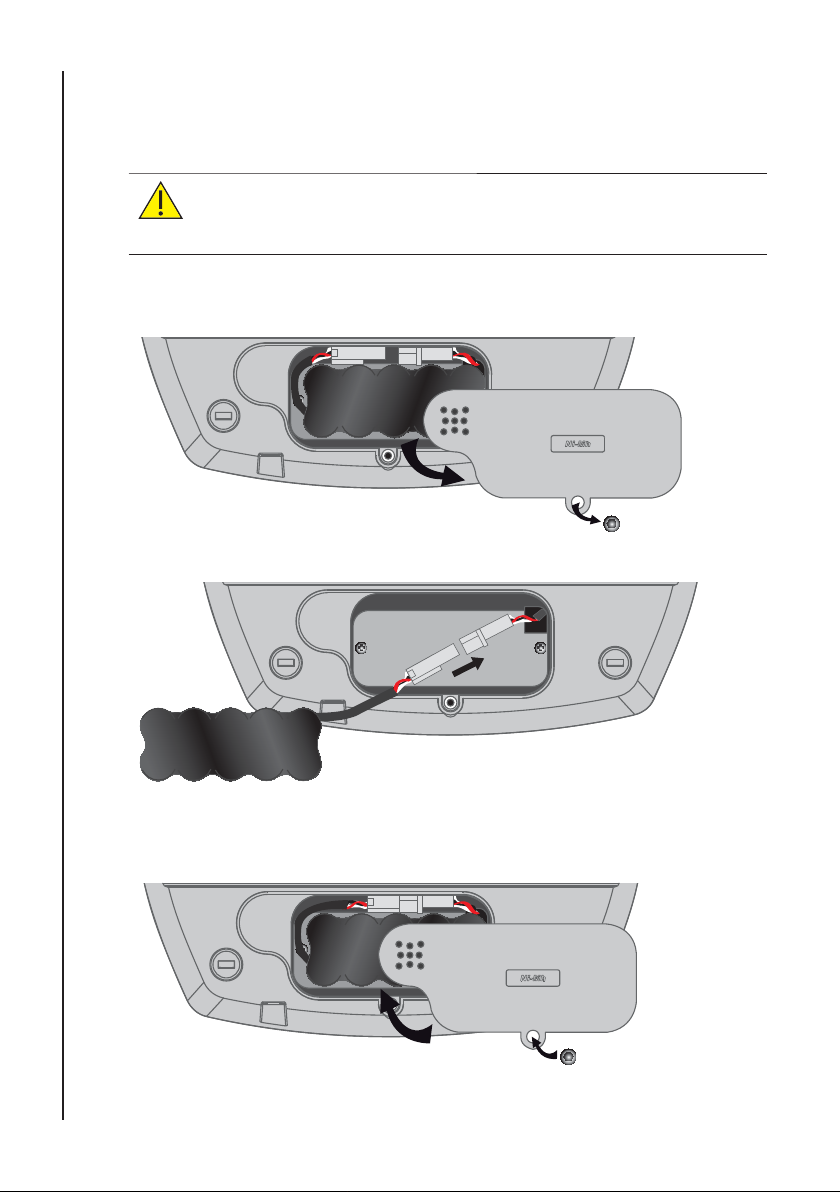
The dopplex Ability is supplied with the internal battery
disconnected. To re-connect the battery, please see instructions
below.
Initial Set-up
1. Invert the unit and remove the battery cover by removing the
securing screw using the allen key provided.
2. Lift the battery out, and connect the battery to the unit.
10
3. Replace the battery. Re-fi t the battery cover and replace the securing
screw with the allen key provided. DO NOT OVERTIGHTEN!
Page 11
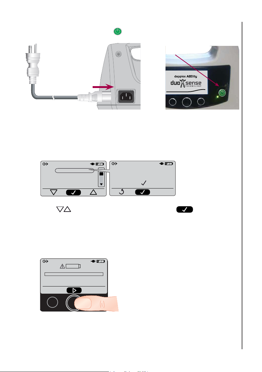
4. Connect the unit to the mains supply (1) and switch it on by pressing
the On/Off button
(2).
1
2
6.2 Setting the Language
When switched on for the fi rst time, the operating language must be selected.
The language selection screen will be displayed.
SET LANGUAGE
English
Deutsch
Francais
Italiano
English
CONFIRM
Press to highlight the required language. Press to Select.
6.3 Battery Conditioning
Initial Set-up
V1.2
Immediately after the language has been selected, the battery conditioning
screen will be displayed.
Note: The battery must be conditioned
before the unit is fi rst used. If the battery is
Battery Conditioning
(Do Not Disconnect From Mains)
not conditioned, battery operation will be
unreliable.
To start battery conditioning, press the centre
softkey.
When conditioning is complete, the unit will switch off automatically. It can then
be switched on and used from mains supply or battery.
Note: Battery conditioning can take up to 10 hours to complete.
11
Page 12

7. Use Environment
Dopplex Ability is suitable for use in hospital, primary care and community
settings. It must not be used outdoors, or in any environment where it may
come into contact with water.
A couch, or similar level support surface is required for the patient to lie on, and
the main unit requires a table or similar for support. Alternatively, a roll stand is
available as an accessory, part number ACC-VAS-013.
Use Environment
Use in strong sunlight should be avoided as display visibility is greatly reduced.
The patient support surface must be wide enough for the patient to be able to
allow their arms to lie comfortably at their sides. The patient’s arms must be
completely relaxed during the test and not pulled tight against the body. The
couch should be separated from adjacent walls etc. as pressure on the arms or
cuffs must be avoided. The patients heels must be supported on the couch and
not be allowed to overhang the end.
The test environment should be reasonably quiet, as excessive ambient noise
may prevent the patient from relaxing; an important test requirement.
WARNING: It is important for safety that the use environment is
well-lit to reduce the risk of persons tripping over the cables and
tubes. Use is not recommended in areas that are used as access
walkways.
12
Page 13

8. Line (Mains) Power Operation
Dopplex Ability is supplied with a plug-in mains lead, fi tted with a 3 pin line plug.
Connect the power cable to the line power socket. If a good, reliable earth is
not available operate the dopplex Ability from its internal battery pack.
Note: To isolate the dopplex Ability from the mains or line supply, disconnect the
power cable from the mains inlet at the rear of the unit.
8.1 Fuses
Internal fuses are fi tted in both the live and neutral lines. Correctly rated fuses
must be fi tted as below:-
T1AH 250VAC
Fuses must only be replaced by a suitably qualifi ed technician.
Line (Mains) Power Operation
13
Page 14

9. Battery Operation
The internal battery, when fully charged, provides enough power for
approximately ten ABI measurements.
An on-screen indicator shows the state of charge at all times.
Battery charging takes place when the unit is connected to the line (mains)
power. During battery charging, the battery symbol fi lls from left to right. The
time required to fully charge a completely discharged battery is approximately
two hours.
Battery Operation
When the battery reaches a critically low level of charge such that further
use is not possible, the battery symbol will appear in outline, and will fl ash
continuously. The unit will then switch off automatically when the battery is
completely discharged.
If the battery is disconnected for any reason, it must be conditioned immediately
after re-connection. Refer to section 12.3.1 (h) for instructions. Failure to do this
will result in unreliable operation from the battery.
Power Save Functions
When operated from the internal battery, power save functions are enabled:
• After three minutes of no keypad use, the display backlight will switch off.
To switch backlight back on, simply press any of the buttons below the
display once.
14
• After ten minutes of no keypad use, the unit will switch off. To switch the
unit back on, press the power on/off button and hold for three seconds.
Note: Any results will be lost unless a printout has been produced.
Page 15
10. Product Identifi cation
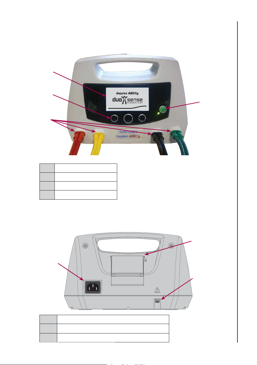
10.1 Front Panel
2
3
V1.2
1
4
1 On/Off button
2 Display
3 Function Buttons
4 Colour Coded Tubes
10.2 Rear Panel
1
Product Identifi cation
2
3
1 Mains Inlet
2 Printer Cover
3 COM Port Connector (USB)
15
Page 16
10.3 Base
3
4
1
Product Identifi cation
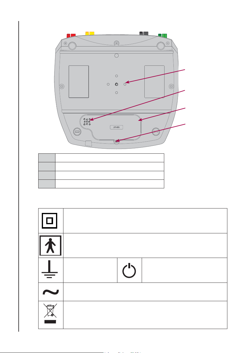
1 Battery Cover
2 Battery Cover Retaining Screw
3 Slide plate Mounting boss
4 Air Filter
10.4 Product Labelling
Dopplex Ability is Class II, double insulated according to the
defi nitions in BS EN 60601-1:1990
Applied parts (cuffs) are type BF according to the defi nitions in BS
EN 60601-1:1990
Functional Earth Power On/Off
2
16
Alternating current (AC)
This symbol signifi es that this product, including its accessories
and consumables is subject to the WEEE (Waste Electrical and
Electronic Equipment) regulations and should be disposed of
responsibly in accordance with local procedures.
Page 17
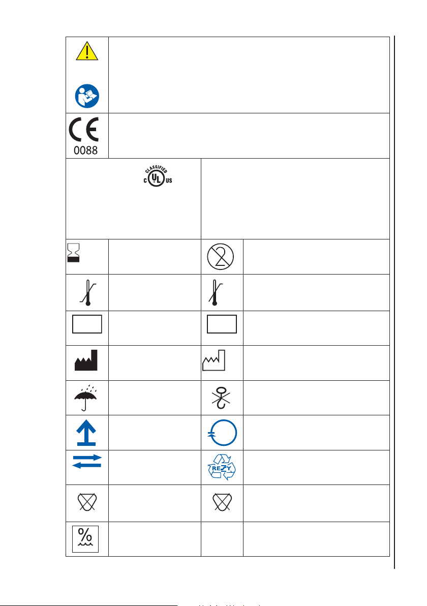
WARNING: ..... Indicates the possibility of death or serious injury
CAUTION: ...... Indicates the possibility of personal injury or
material damage.
Attention, consult accompanying documents / Instructions for Use
This symbol signifi es that this product complies with the essential
requirements of the Medical Devices Directive
93/42/EEC as amended by 2007/47/EC
ANSI/AAMI ES60601-1 (2005, 3rd ed.)
CAN/CSA-C22.2 No 60601-1 (2008)
UL60601-1, CAN/CSA C22.2 No 601.1
Use By Do Not Reuse
YYYY-MM
50°C
Temperature
-10°C
SN
Limitations
Serial Number
Manufacturer
Keep Dry Do not use hook
This way up Contents can be recycled
E364052
Medical
Electrical
Equipment
The UL mark indicates that Dopplex Ability
complies with Underwriters Laboratories
requirements for safety, and is subject to
UL’s follow up services program which
verifi es that the manufactured product
continues to comply with UL’s safety
requirements.
25°C
Upper Limit of Temperature
REF
Reference Number
Date of Manufacture
YYYY-MM
Product Identifi cation
PVC
Max 90% RH
Returnable
packaging
PVC FREE
Does not contain
PVC
Limits of Relative
Humidity
LATEX
Cardboard packaging can be
recycled.
LATEX FREE
Does not contain Latex
17
Page 18

11. System Connection
WARNING: These requirements must be met when a dopplex
Ability is connected to any other electrical equipment, such as a
PC.
1 Non-medical equipment must comply with the relevant IEC or
ISO safety standard. For Information Technology equipment, this
standard is IEC950/ EN60950.
System Connection
2 Medical equipment must comply with IEC60601-1, or equivalent.
3 The confi gured system must comply with the requirements of
IEC60601-1:2005; clause 16.
4 If non-medical equipment (e.g. the PC or printer) with enclosure
leakage currents greater than those allowed by IEC60601-1 is to
be used in the patient environment (within 1.5m of the patient),
the enclosure leakage currents must be brought within the limits laid
down by IEC60601-1. This may be achieved by using a medical
grade isolating transformer. Suitable types are available via
Huntleigh sales agents.
5 Anyone who connects additional equipment to signal input or signal
output parts of the system is confi guring a medical system, and is
therefore responsible for ensuring that the system complies with the
requirements of IEC60601-1:2005; clause 16. If there is any doubt as
to whether your system complies, consult the technical service
department or your local Huntleigh representative.
11.1 USB Port
Dopplex Ability is fi tted with a standard USB port (see item 3, section 10.2 ‘Rear
Panel’) for connection to a personal computer (PC).
Connections to this port should only be made by suitably technically qualifi ed
personnel. For technical specifi cations of this interface, refer to section 16.3.
It is intended to be used for software upgrade purposes, and has no
functionality in normal use.
For further information, contact the service department at the address given in
section 18 of this manual.
18
Page 19
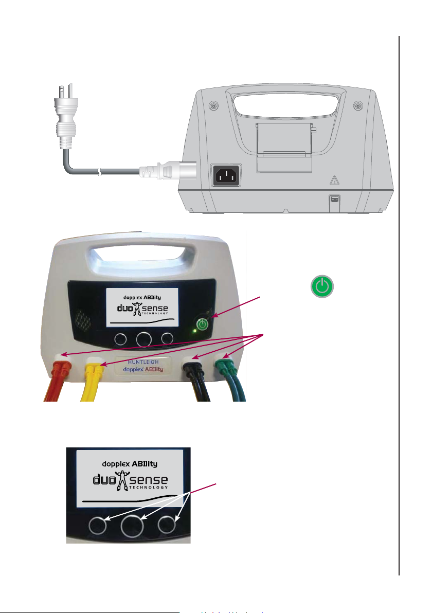
12. Operation
12.1 Getting Started
1. Connect to mains
supply.
V1.2
Operation
2. Press .
3. Connect colour coded
tubing
Note : Use the function buttons below the display to access and
change the system setting and patient measurement menus.
Function Buttons
V1.2
19
Page 20
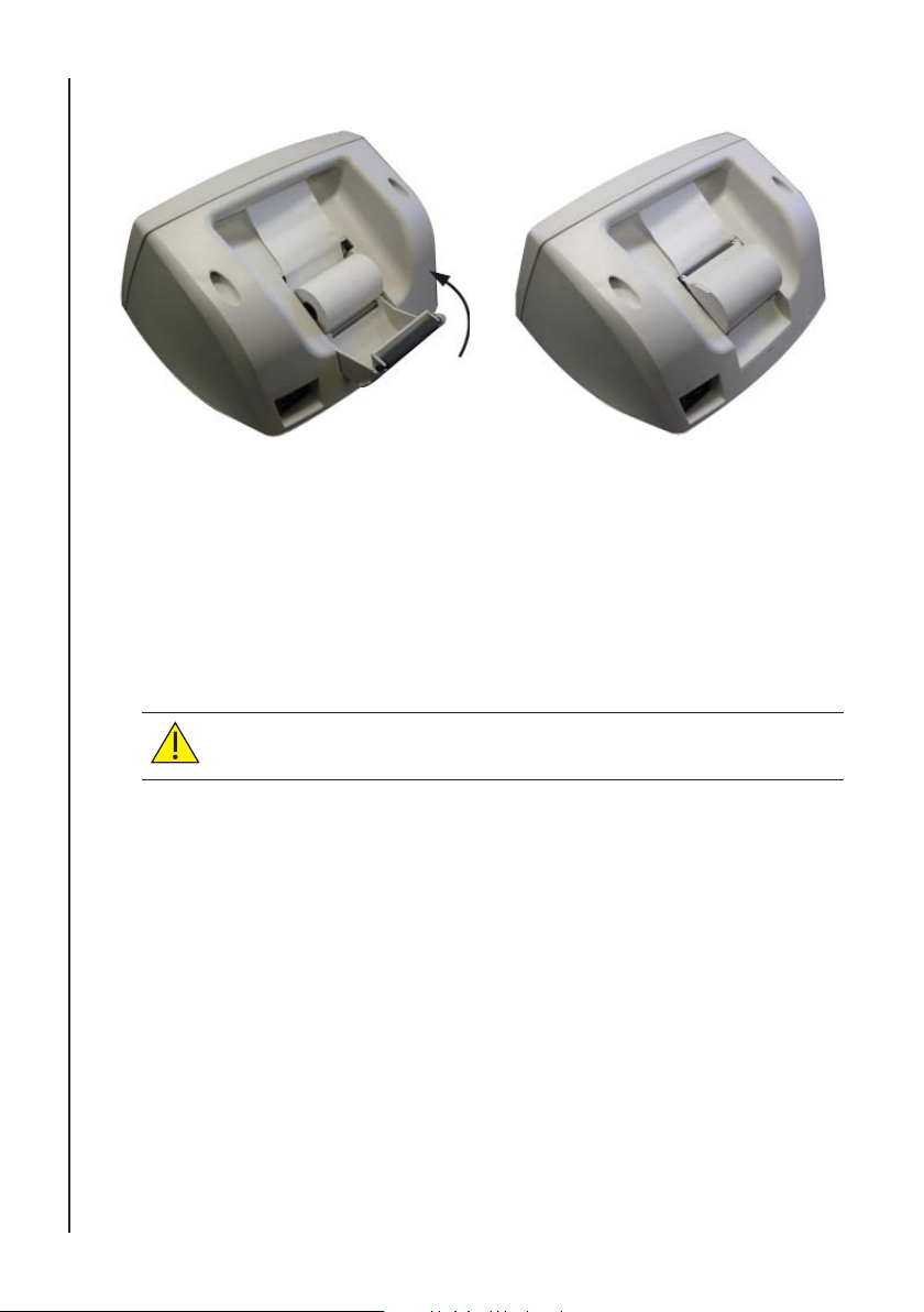
12.2 Loading Paper
Operation
1. Grasp printer door fi rmly and pull gently backwards.
2. Insert paper roll as shown and close printer door. A ‘click’ will be
heard when door is fully engaged.
3. To tear paper, hold fi rmly and tear from one edge towards the front of
the unit.
Note: If using label paper, ensure roll ends are smooth. If not, press end of
roll onto a fl at surface.
20
CAUTION: Only use paper approved by Huntleigh.
Note: The printer lid is designed to detach if forced. To replace, hook the
two lid pivots over the metal rod and press fi rmly downwards. A
positive ‘click’ will be heard as each pivot snaps into place.
Note: Standard (Plain) paper will allow approximately 55 printouts.
Label paper will allow approximately 35 printouts.
Page 21
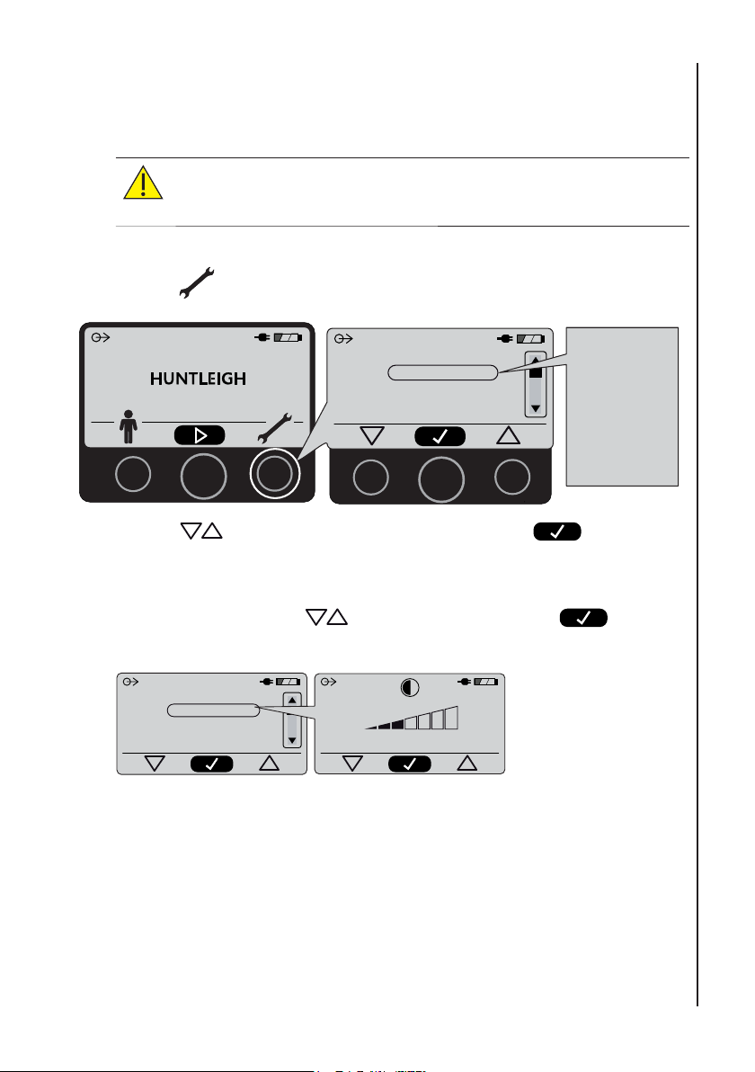
12.3 User Settings
12.3.1 System Settings
CAUTION: Do not apply excessive pressure to the buttons, or
use a sharp implement, such as a pen to press the buttons, as
damage may result.
Operation
1. Press
24/11/10 14:34
to access the system settings.
24/11/10 14:34
Exit
Contrast
Set time/date
Paper type
2. Press to scroll through the setting menus. Press to select.
a. Contrast: Press
to set Contrast value. Press to
Confi rm.
24/11/10 14:34
Exit
Contrast
Set time/date
Paper type
3
Exit
Contrast
Set time/date
Paper type
Audio volume
Classification
Waveforms
Language
Battery conditioner
Demo Mode
Cuff Leak Test
Service menu
21
Page 22
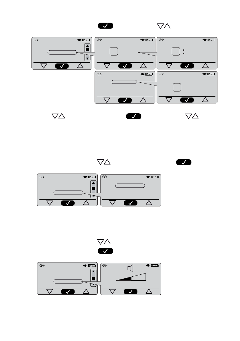
b. Time/Date: Press to Confi rm. Press to set Time.
Operation
24/11/10 14:34
Exit
Contrast
Set time/date
Paper type
SET TIME
12 24
SET DATE FORMAT
dd/mm/yy
mm/dd/yy
yy/mm/dd
SET TIME
10 36
SET DATE
dd/mm/yy
26/03/09
Press to set Date format. Press to Confi rm. Press to set
Date.
Note: As the Time and Date are printed on the printout, the time and date must
be set correctly.
c. Paper Type: Press
24/11/10 14:34
Exit
Contrast
Set time/date
Paper type
to select Paper type. Press to Confi rm.
Plain
Label
22
Note: “Label” type is the adhesive backed thermal label paper (see Section
16.6)
d. Audio Volume: Press to select required volume.
Press
24/11/10 14:34
Contrast
Set time/date
Paper type
Audio volume
to Confi rm.
1
Page 23
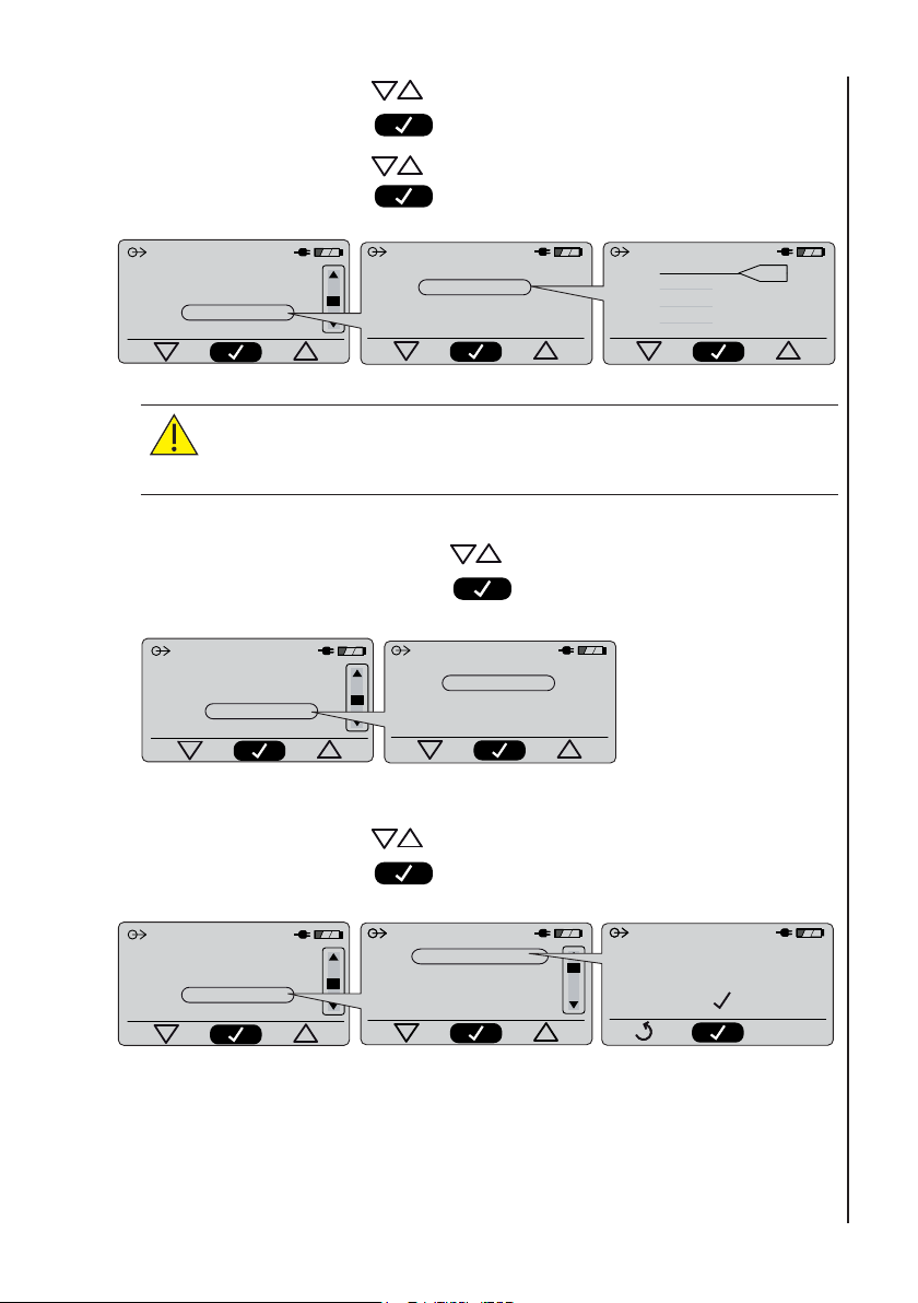
e. Classifi cation: Press to select Classifi cation ON or OFF.
Press
to Confi rm.
Press
Press
24/11/10 14:34
Set time/date
Paper type
Audio volume
Classification
CAUTION: The ABI Classifi cation thresholds, which are
adjustable via the front panel function buttons, should only be
adjusted by a suitably qualifi ed clinician.
f. PVR Waveforms: Press
Press
24/11/10 14:34
Paper type
Audio volume
Classification
Waveforms
to change thresholds.
to Confi rm.
Classification on
Classification off
to select Waveforms ON or OFF.
to Confi rm.
Waveforms on
Waveforms off
Incompressible
Normal
Mild
Moderate
Severe
1.31
0.91
0.81
0.51
Operation
g. Language: Press to select required Language.
Press
24/11/10 14:34
Audio volume
Classification
Waveforms
Language
to Confi rm.
SET LANGUAGE
English
Deutsch
Francais
Italiano
English
CONFIRM
23
Page 24
Operation
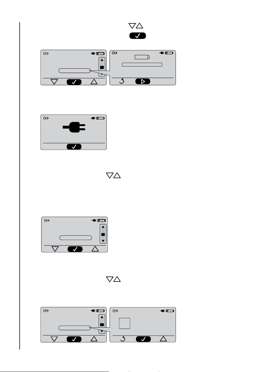
h. Battery Conditioner: Press to select Battery Conditioner.
Press
24/11/10 14:34
Classification
Waveforms
Language
Battery conditioner
Battery Conditioner
(Do Not Disconnect from Mains)
to Confi rm.
If Battery Conditioner is selected when mains (line) power is not connected, the
following message is displayed:-
CONNECT Mains Power
Note: Battery conditioning will take approximately 8-10 hours to complete.
24
i. Demo Mode: Press
to select Demo Mode.
The Demo Mode shows results that have been pre-stored in the Ability. This
mode is useful at exhibitions without the need for a full test.
The printout is clearly marked ‘Demo Mode’ and shows pre-stored results and
artifi cial waveforms.
24/11/10 14:34
Waveforms
Language
Battery conditioner
Demo Mode
j. Cuff Leak Test: Refer to Troubleshooting Section.
k. Service Menu: Press
to select Service Menu. You will require a 4
digit access code to enter this function. Please see Service
Manual for further details.
24/11/10 14:34
Battery conditioner
Demo Mode
Cuff Leak Test
Service Menu
0
xxx
Page 25
12.4 Making a Measurement
12.4.1 Patient Preparation
WARNING: Before fi tting cuffs to the patient, evaluate the cross
contamination risk. For medium/high risk situations, where
the patient has a known infection or skin is not intact, use an
infection control barrier sleeve with aseptic technique.
WARNING: Do not apply cuff directly to non-intact skin. If a
wound is present, ensure a suitable wound dressing is applied,
followed by an infection control barrier sleeve.
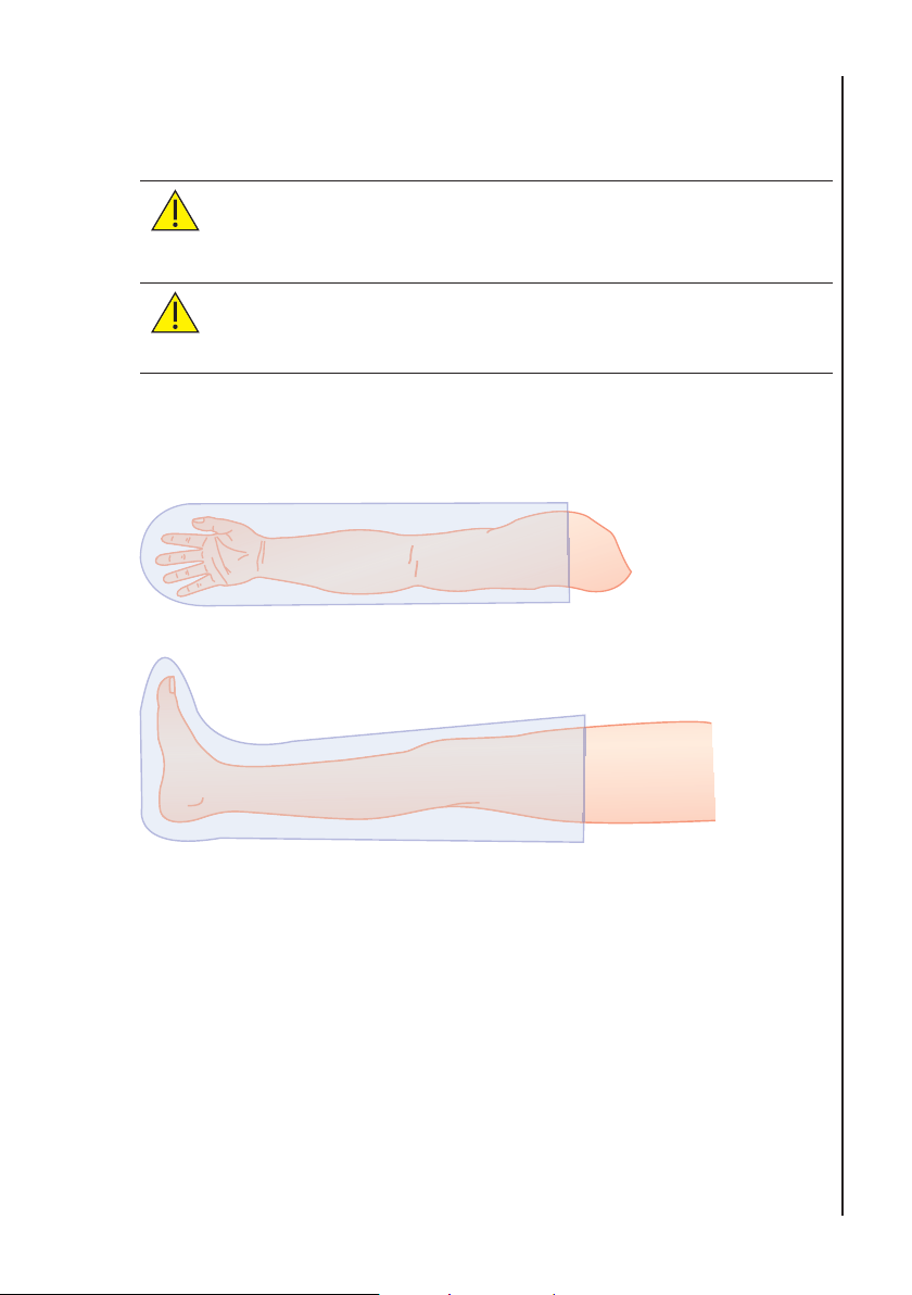
Fitting Infection Control Barrier Sleeves
Arm
Leg
Operation
Note: Remove any trapped air before tightening cuffs.
25
Page 26
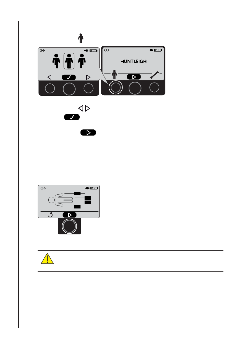
12.4.2 Setting Patient Type
1. Press .
Operation
2. Press to select patient normal or amputee mode. Press
to Confi rm.
11/03/08 14:34
3. Press
to progress to cuff placement screen.
12.4.3 Fitting the Cuffs
1. Position the cuffs on the patient.
CAUTION: Ensure all cuffs are fi tted correctly and aligned on
limbs according to the instructions. Measurement error may
occur if cuffs are fi tted incorrectly.
Please Note! For clarity purposes, the following illustrations show limbs
un-clothed. Cuffs can be fi tted and measurements taken over thin clothing
such as pantyhose, thin shirts and thin socks. Cuffs cannot be fi tted over
sweaters or pants.
26
Page 27
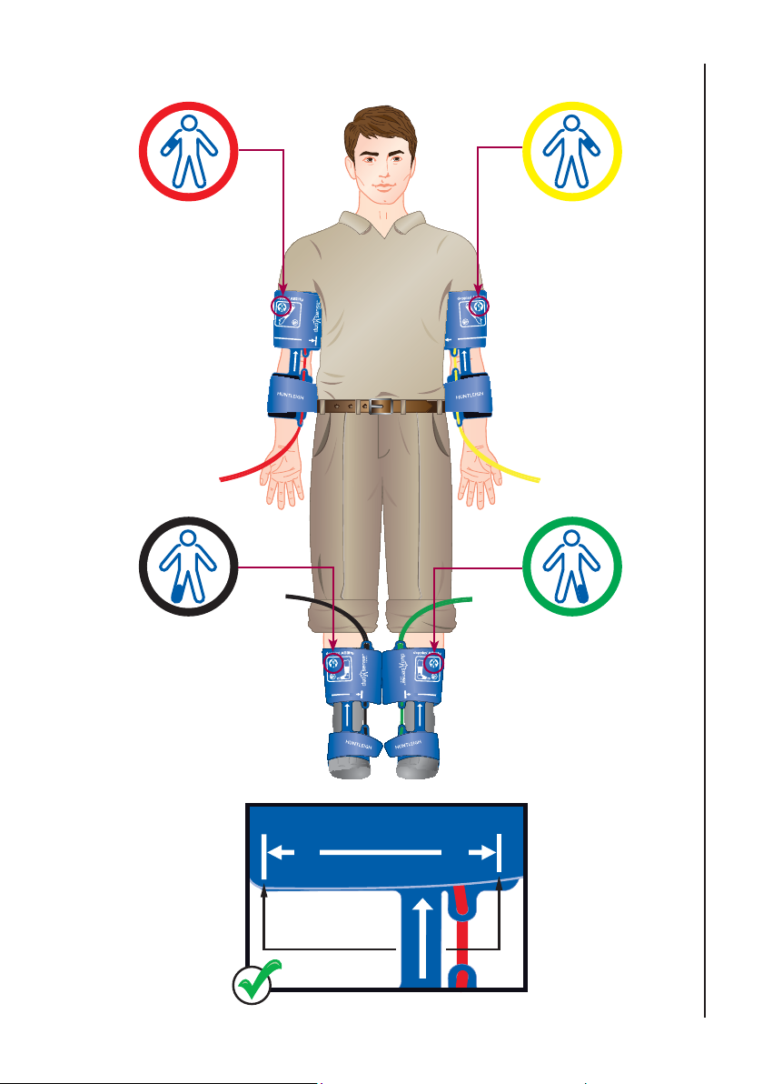
Correct Cuff Placement
REDRIGHT ARM
Operation
YELLOW -
LEFT ARM
BLACKRIGHT ANKLE
Adult
22cm - 36cm (8.7
Ý
- 14.2Ý)
Max
22cm - 36cm (8.7Ý - 14.2Ý)
Min
18cm - 28cm (7.1
Min
Adult
Ý)
- 14.2
Ý
22cm - 36cm (8.7
Max
GREEN -
LEFT ANKLE
Adult
)
Ý
Ý - 11.0
Max
Adult
18cm - 28cm (7.1Ý
Max
Adult
- 11.0
Ý
Mi
Max
27
Page 28
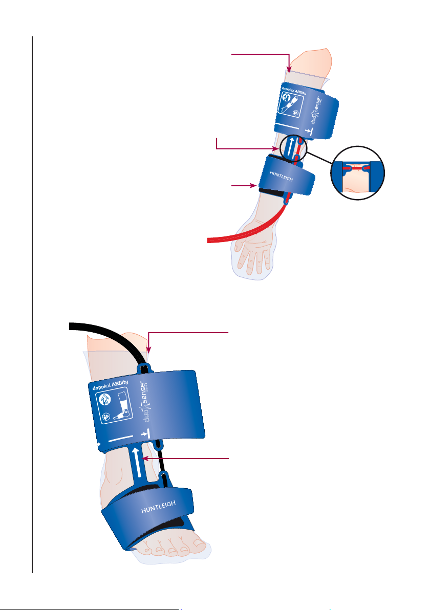
Arm
Infection Control Barrier Sleeve
Note: Remove any trapped air before
tightening cuffs.
Operation
Place strap with white line over
the inside of the arm
(Over brachial artery)
Place distal chamber just below
elbow, on largest diameter part
of the forearm.
Leg/Foot
Adult
22cm - 36cm (8.7
Ý
- 14.2
Ý
)
Max
Infection Control Barrier Sleeve
Note: Remove any trapped air
before tightening cuffs.
28
Adult
18cm - 28cm (7.1
Min
Ý - 11.0
)
Ý
Max
Ensure strap is fi tted on top of
the foot.
(Over anterior tibial artery)
Page 29
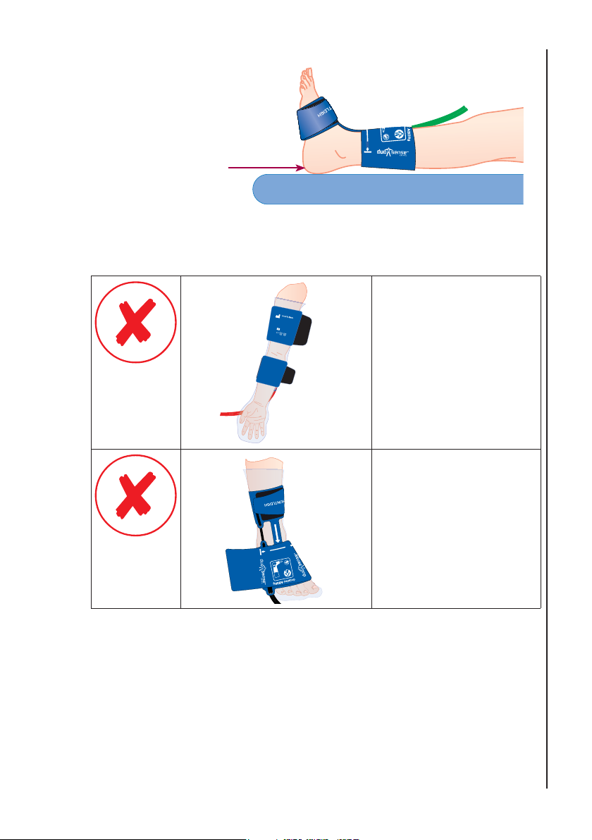
Foot Position
Ensure patients heel
is resting on the
couch. Do not rest
the leg on the cuff
as this may affect
measurement result.
Incorrect Cuff Placement
Diagnostic Products Division
Email: [email protected]
www.huntleigh-diagnostics.com
Made in UK
ACC-VAS-023
LATEX
0088
18cm - 28cm (7.1
Adult
Ý
- 11.0Ý)
Min
Operation
Ensure the cuffs are not
Huntleigh Healthcare Ltd
35 Portmanmoor Road
Cardi, CF24 5HN. UK
Tel: +44(0) 29 2048 5885
PVC
rotated around the limb.
Measurement error or
failure to take correct
measurement may
occur if cuffs are fi tted
incorrectly
Ensure the cuffs are fi tted
in the correct orientation.
Measurement error or
failure to take correct
Min
18cm - 28cm (7.1Ý - 11.0Ý)
Max
Adult
measurement may
occur if cuffs are fi tted
incorrectly
Note: Take great care to ensure that the tubing is not kinked or
obstructed in any way. Do not touch cuffs or tubing when
measurement is in progress.
Note: The patient must lie supine, be relaxed, remain still, and refrain
from talking, coughing etc.
Note: Always brief the patient before the test, explaining that the cuffs
will tighten, and that the test will take approximately 3 minutes
to complete.
29
Page 30
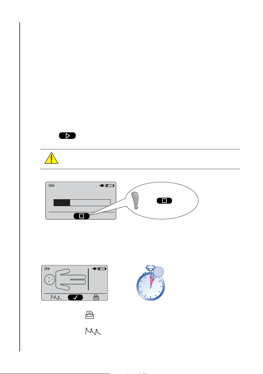
12.4.4 Performing the test
Patient Briefi ng
The patient should always be briefed on what to expect during the test to avoid
unnecessary distress. This should describe how the cuffs will infl ate, and then
Operation
after a short delay the arm cuffs will both tighten, followed by tightening of the
ankle cuffs. After approximately three minutes all cuffs will defl ate and the test
will be complete.
They should be advised that the test can be stopped at any time if they fi nd the
test unbearable. This is done by pressing the centre key below the display.
The patient should also be asked to remain perfectly still during the test, and not
to talk or cough etc.
Press
to start measurement.
CAUTION: Always remain with the patient and monitor test
progress.
Test In Progress
IMPORTANT!
Press to stop
the test at any time.
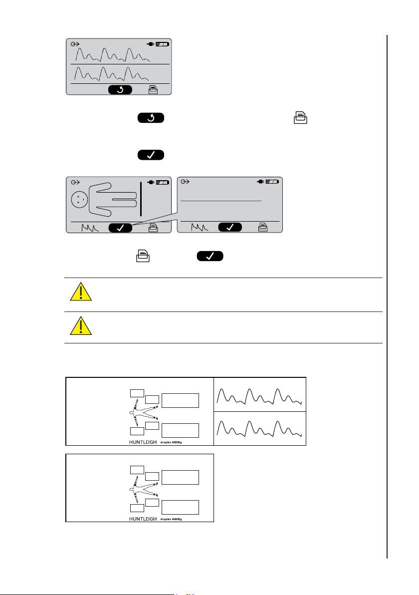
12.4.5 Viewing the results
1. The results will be displayed within 3 minutes.
122
120
129
126
1.06
ABI
1.03
L
R
2. Press to print results.
3
min
0
55
5
10
50
45
15
20
40
353025
30
3. Press
to show PVR waveforms.
Page 31
L
R
4. Press to return to previous screen or to print PVR
waveforms.
Operation
5. Press
122
129
126
120
to view the ABI Classifi cation.
1.06
ABI
1.03
L
R
Normal
Normal
1.06
ABI
1.03
6. Press to print or to start a new test.
CAUTION: Always observe ABI value, not only classifi cation, as
marginal results could be overlooked.
CAUTION: Systolic pressures are displayed for information only,
and should not be used to form a clinical diagnosis.
12.4.6 Example reports
Name.........................................
.....................................................
ID ................................................
.....................................................
Comments ..............................
.....................................................
.....................................................
.....................................................
.....................................................
120
124
11/03/08 14:34
136
1.10
Normal
ABI
134
1.08
Normal
R
771AXXXXXXXX-XX
L
V2.220
L
R
Name.........................................
.....................................................
ID ................................................
.....................................................
Comments ..............................
.....................................................
.....................................................
.....................................................
.....................................................
120
124
11/03/08 14:34
136
1.10
Normal
ABI
134
1.08
Normal
R
771AXXXXXXXX-XX
L
V2.220
Note: Always annotate patient information on report.
31
Page 32
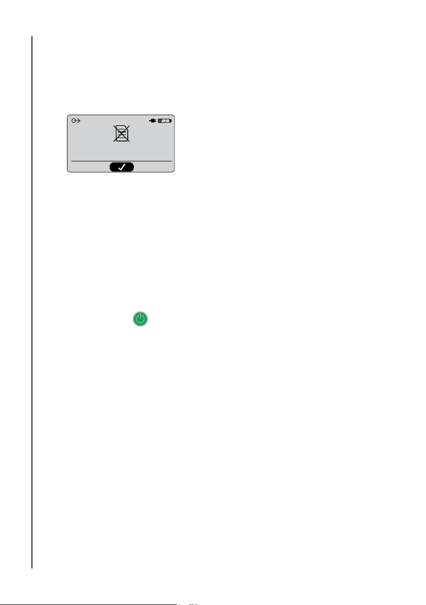
12.4.7 Paper Low Indication
When the paper approaches the end of the roll, a red marker line will be visible
on the report. Approximately 5 reports with PVR or 8 reports without PVR can
be printed before the paper runs out. If the print button is pressed when the
paper has run out, the following message will be displayed:-
Operation
No Paper
12.4.8 Report Storage Guidance
Store in a cool dry place. Do not expose to sunlight, temperatures greater than
100°F (38° C), relative humidity over 80%, or place in contact with adhesives,
adhesive tapes or plasticizers such as those found in all pvc page protectors.
It is recommended that reports are photocopied for optimum storage lifetime.
12.5 Switching the Unit Off
Press and hold button for approximately 3 seconds to switch the unit off.
32
Page 33

13. Troubleshooting
This section gives some of the more common problems encountered during use
together with possible causes. If the problem cannot be located after consulting
the table in this section, the dopplex Ability should be switched off, disconnected
from mains power source and a qualifi ed technician should be consulted.
Before attempting trouble-shooting, verify that the power cable is properly
connected to both the dopplex Ability and the mains power source.
SYMPTOM POSSIBLE CAUSE / REMEDY
Green power indicator not illuminated 1. Power cable not connected to live
power source
2. Defective power cable
3. Mains input fuses blown
Unit will not turn on Connect to live power source
Printout blank Paper inserted incorrectly
Battery Low symbol showing Connect to the power source
Battery does not hold charge Select ‘Battery Conditioner’ menu
(section 12.3.1) or replace battery
No results produced Check all tubes and cuffs and repeat
test.
Only one ankle cuff infl ates Check patient type is correctly set
(See section 12.4)
Display not clear Contrast setting is incorrect (See
section 12.3.1)
Printout not clear on label paper Check setting of paper type (See
section 12.3.1)
Paper printout jams Incorrect paper fi tted
Unit will not fi t to roll stand Ensure mounting plate is fi tted
correctly
Cuff takes a long time to infl ate Check air fi lter or check cuffs for
leaks
Troubleshooting
33
Page 34
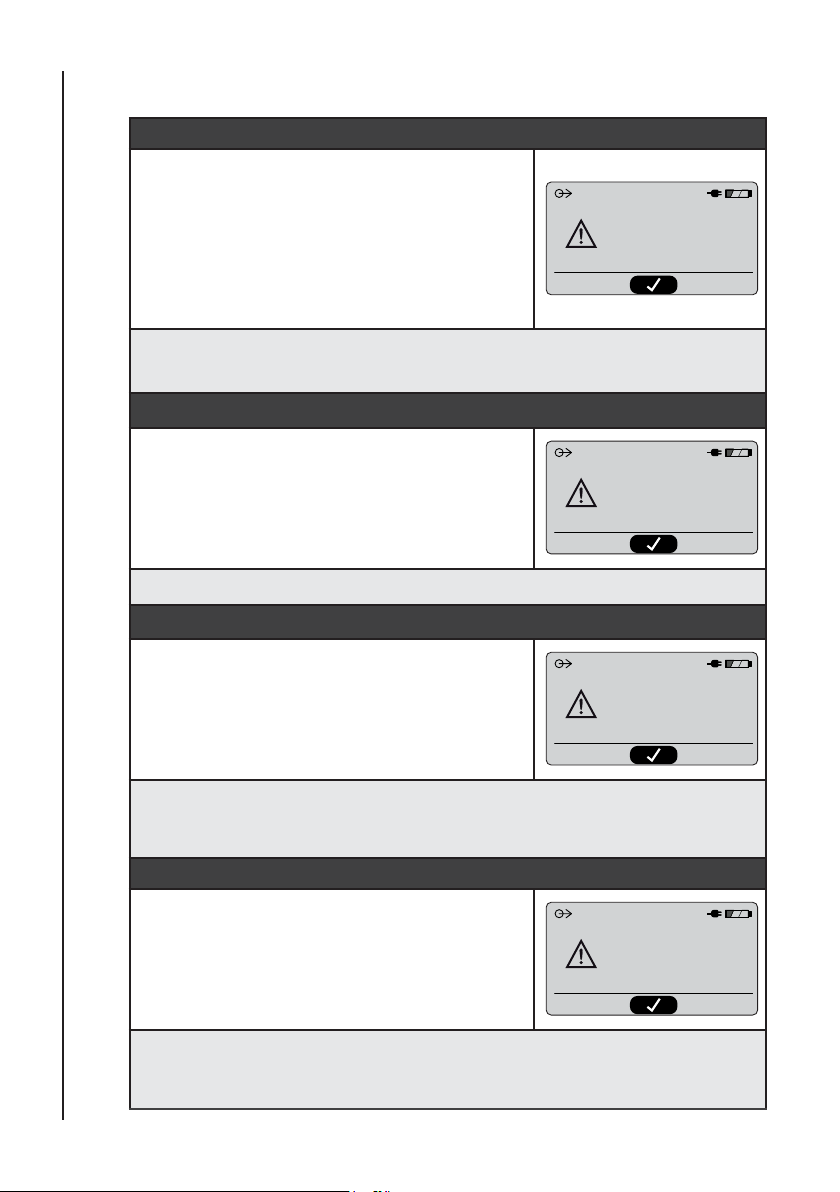
13.1 Error Messages
Cuff Not Connected
If the user fails to connect one or more of the
cuffs to the unit or the cuffs are not tensioned
correctly, one of the following messages is
displayed:-
• Left / Right Arm Cuff - Not Connected
• Left / Right Ankle Cuff - Not Connected
Troubleshooting
• Arm Cuffs / Ankle Cuffs - Not Connected
Recommended Action: Check that the cuffs are properly connected, and are
fi tted snugly. Refer to section 12.4.3.
Cuff Air Leak
If an air leak is detected in the cuffs or tubing,
one of the following messages is displayed:-
• Left / Right Arm Cuff - Leak Detected
• Left / Right Ankle Cuff - Leak Detected
• Arm Cuffs / Ankle Cuffs - Leak Detected
Recommended Action: Run the Cuff Leak test in Section 13.2.
Infl ation Problem
If any cuff fails to infl ate correctly, one of the
following messages is displayed:-
• Left / Right Arm Cuff - Infl ation Problem
• Left / Right Ankle Cuff - Infl ation Problem
• Arm Cuffs / Ankle Cuffs - Infl ation Problem
Recommended Action: Check cuffs are fi tted correctly and tubing is
not kinked or obstructed. If problem persists, refer to Service Manual for
diagnostic test procedures.
Left Arm Cuff - Not Connected
Refer To User Manual
Left Arm Cuff - Leak Detected
Refer To User Manual
Left Arm Cuff - Inflation Problem
Refer To User Manual
34
Excess Pressure
If excess pressure is detected in any cuff, one of
the following messages is displayed:-
Left Arm Cuff - Excess Pressure
• Left / Right Arm Cuff - Excess Pressure
• Left / Right Ankle Cuff - Excess Pressure
• Arm Cuffs / Ankle Cuffs - Excess Pressure
Recommended Action: Ensure the cuffs are not obstructed and are free
to infl ate properly. Do not squeeze the cuffs during tests, or allow them to
become trapped, e.g. against a wall or similar hard surface.
Refer To User Manual
Page 35
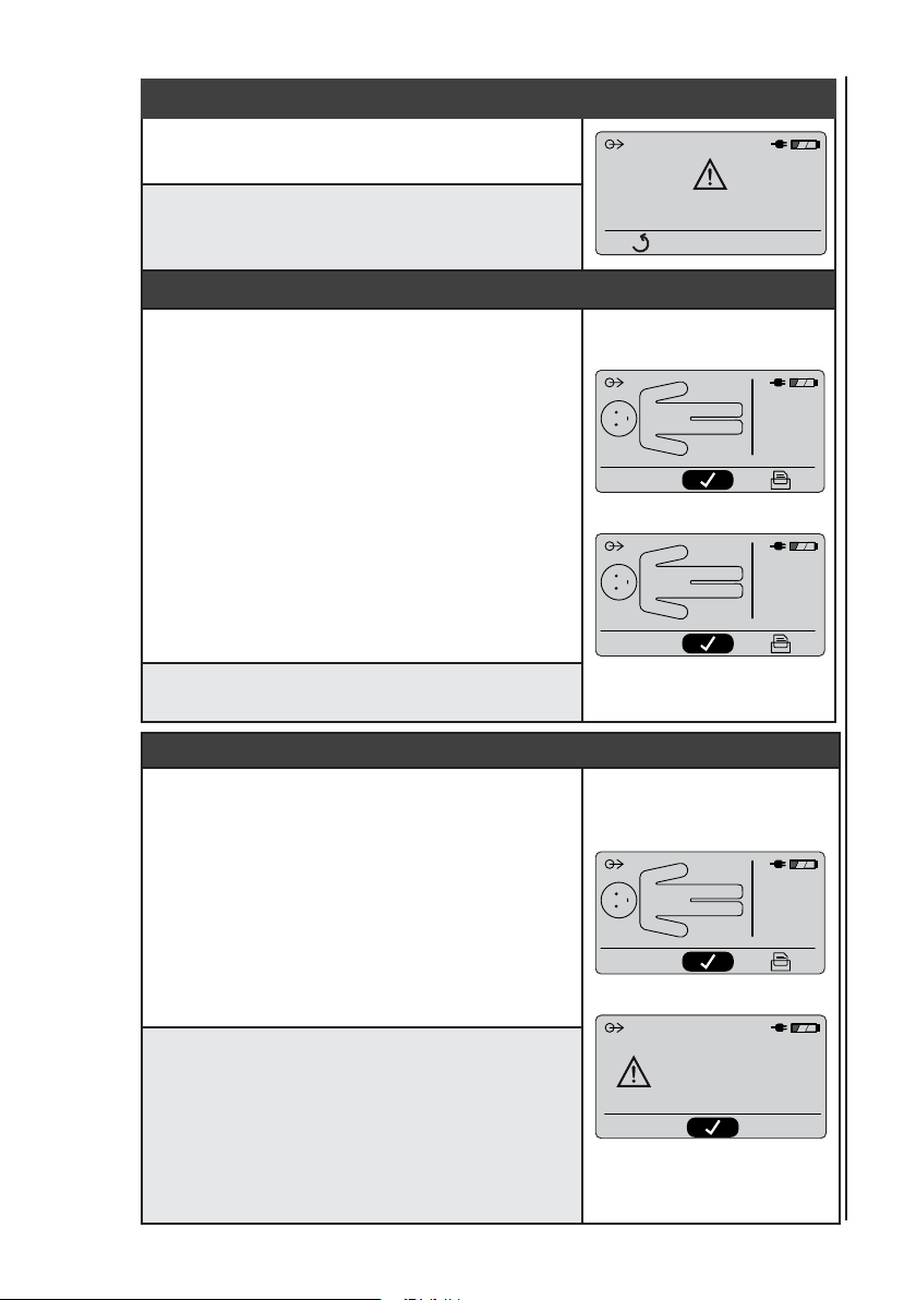
Internal Fault
If an internal fault is detected, the following
message is displayed on the screen:-
Recommended Action: The unit must be
referred for servicing and/or repair. Refer to
contact details at the rear of this manual.
Systolic Pressure Out of Measureable Range
If the pressure in an occlusion chamber is
insuffi cient to completely occlude bloodfl ow, the
systolic pressure value will be replaced by:-
“- - -”
and the corresponding ABI value will be
replaced by:
“- .- -”
For the ankles, this indicates a possible
incompressible artery, or that systolic pressure is
greater than 205 mmHg.
For the arms, this indicates that systolic
pressure may be less than 80 mmHg, or greater
than 230 mmHg.
Recommended Action: Follow local clinical
protocols for patient referral.
Unable to Calculate Systolic Pressure
If the software algorithms are unable to calculate
a systolic pressure, the systolic value will be
replaced by:
“ ? ”
and the corresponding ABI value will be
replaced by:
“- .- -”
If this occurs on both ankles, the results display
will be replaced by the “CANNOT MEASURE”
screen.
Recommended Action: A possible cause is
patient movement or incorrectly fi tted cuffs, so
a repeat test can be performed after checking
cuffs and asking the patient to remain as still as
possible.
Note: When performing repeat tests on the
same patient, allow at least 5 minutes for
stabilisation between tests.
Internal Fault AAA:XXXX
Refer To Service Manual
124
- - 196
120
- - -
134
136
- - -
124
134
120
?
CANNOT MEASURE
REPEAT TEST
-.--
ABI
1.10
-.--
ABI
-.--
1.08
ABI
-.--
Troubleshooting
L
R
L
R
L
R
35
Page 36
13.2 Cuff Leak Test
The integral cuff leak test is able to test two cuffs at a time for leakage. Each
pair of cuffs is connected to the ankle cuff connectors (black and green) on the
unit. The arm cuff channels (red and yellow) are not used in this test.
Procedure:
1. Connect a pair of cuffs to the ankle cuff connectors (black & green) on the
unit.
Troubleshooting
2. Open the cuffs and lay them fl at on a suitable surface.
3. Connect the unit to a mains supply and switch on.
4. Select the Setup menu (
5. Scroll down to Cuff Leak Test and press accept ( ).
6. Press accept (
7. The cuffs will be infl ated to a test pressure, and then defl ated. Do not touch
the cuffs during the test .
8. The test result will be displayed as Pass or Fail for each ankle channel.
9. Repeat for the remaining pair of cuffs.
).
) to begin the test.
36
Page 37

13.3 Guidance for Reliable Performance
To improve the reliability of the results, the following points should be
noted:
• Cell/smart phones etc, must be at least 4 feet away from the unit.
• The couch should be separated from adjacent walls etc. as pressure on the
arms or cuffs must be avoided.
• Check that the clothing is not too thick. The cuffs can be applied over thin
shirts, socks or pantyhose. If in doubt, remove the socks.
• Always brief the patient before the test, explaining that the cuffs will tighten,
and that the test will take approximately 3 minutes to complete.
• The patient’s arms must be supported by the couch.
• The patient’s arms must be completely relaxed during the test and not
pulled tight against the body.
• The patients heels must be supported on the couch and not be allowed to
overhang the end.
• The cuffs must have the correct tension – a snug fi t (taut but not tight)
• The arm sense chamber must be located just below the elbow on the
largest diameter part of the forearm. The connecting strap between the two
chambers should not be fl at.
• The patient must lie supine, be relaxed, remain still, and refrain from
talking, coughing etc.
• The operator must not talk to the patient – this always prompts responses
from the patient.
• The operator must not touch the cuffs or knock the tubing during the test.
• When performing repeat tests on the same patient, allow at least 5 minutes
for stabilization between tests.
Troubleshooting
37
Page 38
14. Care and Cleaning
14.1 General Care
All Huntleigh Products have been designed to withstand normal clinical use,
however they can contain delicate components which should be handled and
treated with care.
Periodically, and whenever the integrity of the system is in doubt, carry out a
check of all functions as described in the relevant section of the IFU. If there are
any defects to the housing contact Huntleigh or your distributor for repair or to
Care and Cleaning
order a replacement.
Please ensure that you check with your facility’s local infection
control policy and medical equipment cleaning procedures.
Observe warnings and guidance on cleaning fl uid labelling
regarding use and personal protective equipment (PPE).
Do not use abrasive cloths or cleaners.
Do not use automatic washers or autoclaves.
38
Do not use Phenolic detergent based disinfectants, solutions
containing cationic surfactants, ammonia based compounds or
perfumes and antiseptic solutions.
If detergent or disinfectant wipes are used ensure that excess
solution is squeezed from the wipe prior to use.
Always switch off Products and disconnect from the AC supply
before cleaning and disinfecting.
Do not allow any fl uid to enter the products and do not immerse
in any solution.
Always wipe off disinfectant using a cloth dampened with clean
water.
Page 39
14.2 Cleaning and Disinfecting Cuffs and Tubing
Before fi tting the cuffs to the patient, evaluate the cross-contamination risk
according to the defi nitions in the tables below:
1. Low Risk
For low-risk situations, when infection control barrier sleeves are not used,
clean and disinfect the cuffs & tubing after use following the instructions below:
Defi nition Procedure
Normal use or low risk
situations including
patients with intact
skin and no known
infection.
2. Medium / High Risk
Defi nition Procedure
The patient has a
known infection, or
skin is not intact.
1. Clean with soft cloth and a mild, neutral detergent
@ 40°C (104°F)
2. Disinfect using a 70% isopropyl alcohol wipe
or chlorine releasing agent @ 1000ppm available
chlorine
3. Wipe with a cloth dampened in clean water.
4. Completely dry with a clean lint-free cloth
Because of the nature of the cuff materials, effective
cleaning and disinfection in high risk situations is not
practical. Therefore, infection control barrier sleeves
are recommended as an alternative, to prevent cuff
contamination.
Care and Cleaning
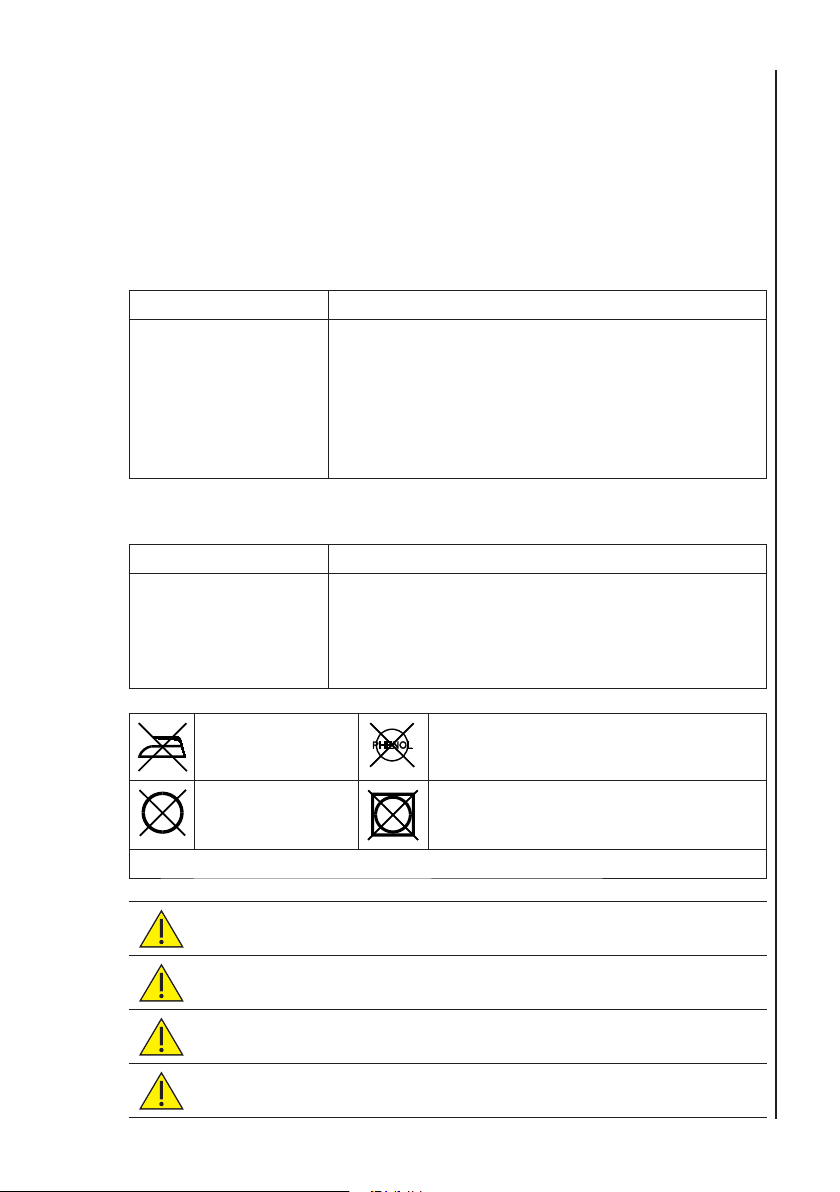
Do not iron Do not use phenol or phenol-derivative
disinfectant.
Do not dry clean Do not tumble dry.
Do not machine wash. Do not immerse tubeset in water.
CAUTION: Do not allow any fl uid to enter the cuff tubing.
CAUTION: Do not use abrasive cleaning methods.
CAUTION: Do not use alternative cleaning agents or methods as
permanent damage is likely.
CAUTION: Inspect cuffs after cleaning and prior to use.
39
Page 40

Cuff Inspection:
All four cuffs should be regularly inspected. Examine the outer cuff surfaces for
material damage, splitting, fraying etc. Make sure that labelling is clearly legible.
Check the cuff tubing and connections for damage, splits etc. If in any doubt
as to the condition, the cuff(s) should be replaced. In any case, cuffs should be
replaced every two years.
14.3 Cleaning and Disinfecting the Ability Unit
Always keep the external surfaces clean and free of dirt and fl uids using a clean
dry cloth.
1. The unit can be wiped with a soft cloth dampened with a mild
detergent solution in water. Avoid the electrical contacts, apertures
and connectors.
2. Wipe any fl uids from the surface of the product using a clean dry
cloth.
3. Wipe with a cloth dampened in 70% Isopropyl Alcohol.
4. Completely dry with a clean, dry lint free cloth.
Care and Cleaning / Maintenance
If the product becomes contaminated, follow the ‘low risk’ cleaning and
disinfection instructions given above, but use a more concentrated chlorine
agent at 10,000 ppm available chlorine.
Warning: Repeated and unnecessary use of concentrated
solutions will result in damage to the product. Do not allow
sodium hypochlorite solutions to come into contact with metal
parts.
15. Maintenance
It is recommended that the Ability unit and accessories are inspected and tested
at least annually. Full details are included in the Service Manual which can be
obtained from Huntleigh Healthcare Service Department, quoting the unit serial
number (email: [email protected] ).
Suitable test equipment and a full range of spare parts are also available.
Please refer to service manual for further information and part numbers.
40
Page 41
16. Accessories
16.1 Carry bag
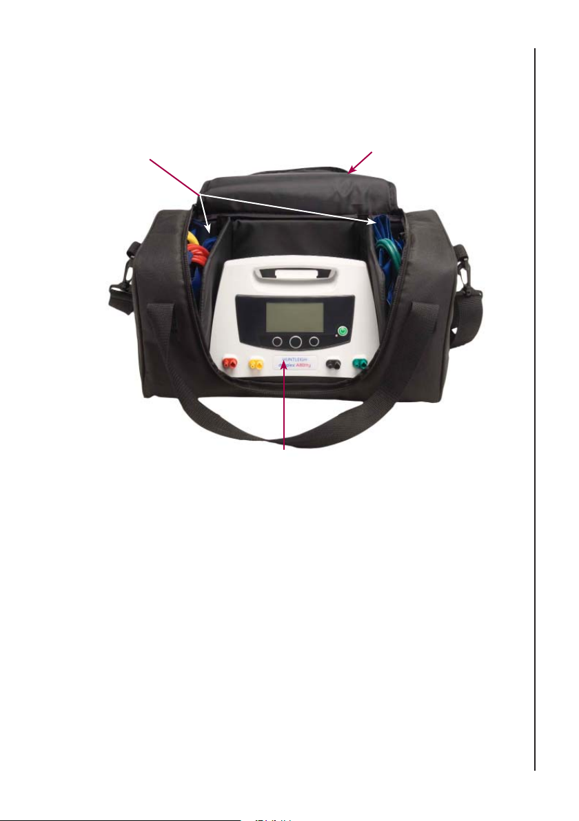
Side compartments
for cuff storage
Central compartment for
dopplex Ability
A carry bag is available for the dopplex Abilty. It is highly recommended that the
bag is always used whenever the unit is transported.
Compartment in top fl ap
can store Infection Control
Barrier Sleeves
Accessories
The bag includes a central compartment for the main unit. The side
compartments each hold two cuffs. The cuff tubing must be wrapped around the
cuffs neatly, before they are placed in the bag. This helps to keep the tubing and
cuffs away from the zipper and avoids damaging them.
A shoulder strap is included for carrying comfort.
The bag includes a separate compartment at the rear for storing paperwork and
infection control barrier sleeves.
To avoid damage to the mains cable, it should be unplugged from the unit.
41
Page 42
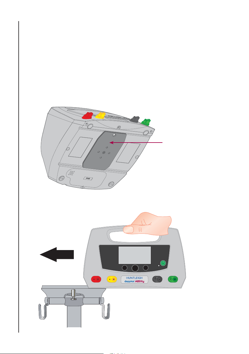
16.2 Roll Stand
A roll stand is available which provides a stable means of support, and a
convenient means of moving the unit around within the building.
Fitting the Ability Unit to the Roll Stand
The roll stand support incorporates a slide mount that allows the unit to be fi tted
Accessories
and removed safely and quickly.
Note: To use the roll stand, a mounting plate (Part No ACC-VAS-012) is required
to be fi tted to the base of the Ability unit.
1. With the mounting plate fi tted to the ability unit, slide the unit
sideways, ensuring that the plate is aligned with the grooves in the
roll stand support surface.
Mounting Plate
42
Slide Unit Sideways onto the
roll stand.
Ensure unit is fi tted in the
correct orientation.
Page 43
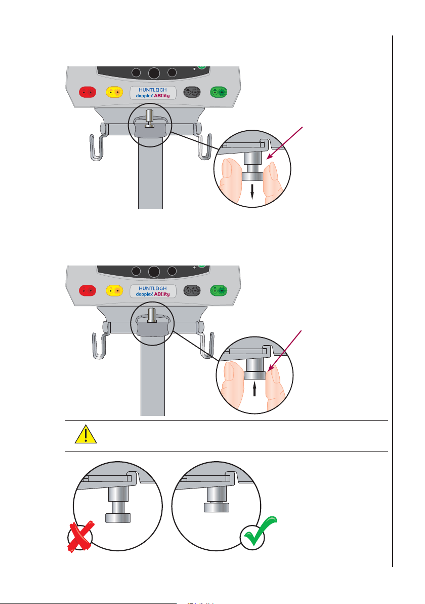
2. Locate the lock pin and pull downwards so that the Ability unit can be
positioned centrally on the support surface.
Pull lock pin
downwards
3. Release the lock pin and ensure it locates in the hole in the mounting
plate. This can be verifi ed by attempting to slide the Ability unit
sideways. It must be securely locked into position.
Release lock pin.
Ensure lock pin is
properly engaged
Accessories
CAUTION: Ensure that the Ability unit is securely fi tted to the
roll stand and that the lock pin is properly engaged.
43
Page 44
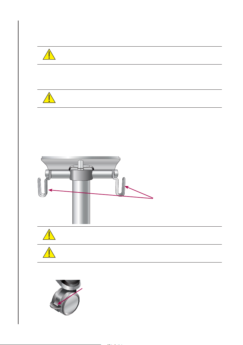
Adjusting the Platform Height
The black knob on the roll stand upright must be slowly rotated anti-clockwise
whilst supporting the platform.
CAUTION: Do not allow the platform to drop, as product
damage and personal injury may result.
Accessories
Lower the platform to the desired height and rotate the black knob clockwise to
lock it fi rmly into position.
CAUTION: Ensure the platform is fi rmly locked into position
before use.
Cuff Storage
The cuffs should be stored in the basket provided on the roll stand. The tubing
should be fi tted to the tubing supports located immediately beneath the support
platform.
CAUTION: Do not store other equipment in the basket.
Supports for cuff
tubing
44
CAUTION: Ensure the tubing is securely supported before
moving the roll stand.
Brakes
Two of the roll stand castors are fi tted with brakes. Apply
the brakes when the stand is stationary.
Page 45
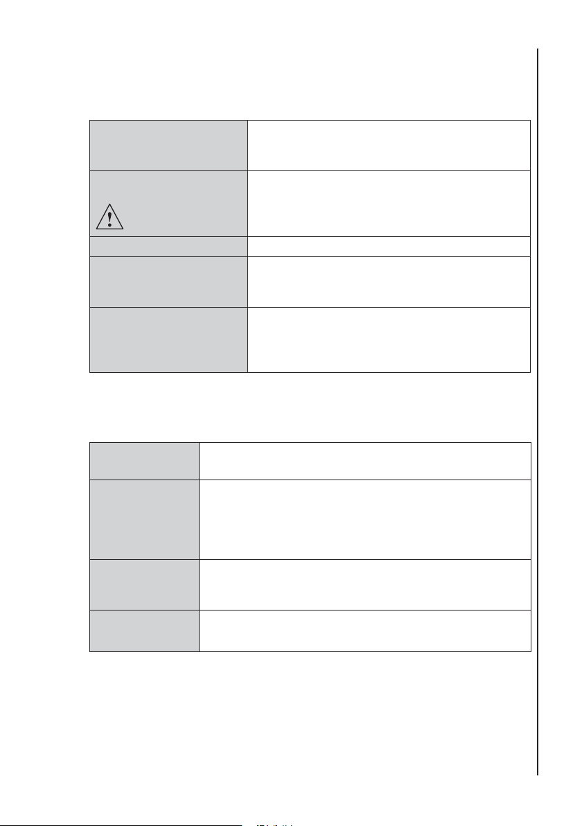
17. Specifi cations
17.1 Equipment Classifi cation
Type of protection
against electric shock.
Degree of protection
against electric shock
Mode of operation. Continuous
Degree of protection
against harmful ingress
of particles and/or water.
Degree of safety of
application in the
presence of a fl ammable
anaesthetic
17.2 Performance
Systolic
Pressure Range
ABI Dopplex Ability provides valid ABI results for at least
PVR Dopplex Ability provides fi ltered PVR waveforms from the
Maximum Cuff
Pressure
Class II and Internally powered equipment with
a functional earth terminal, which provides a
ground path for the internal mains fi lter.
Type BF - equipment with an applied part.
Specifi cations
IP30
Equipment not suitable for use in the presence of
a FLAMMABLE ANAESTHETIC MIXTURE WITH
AIR, OXYGEN OR NITROUS OXIDE
Arms : 80 - 220 mmHg
Ankles : 55 - 205 mmHg
80% of the patients tested. Valid results consist of both
compressible vessels (where Dopplex Ability agrees
with the Doppler method to ± 0.28 for the 95% limits of
agreement), and incompressible vessels.
ankles with -3dB cut-off frequencies at 0.35 Hz and
10 Hz.
230 mmHg
45
Page 46
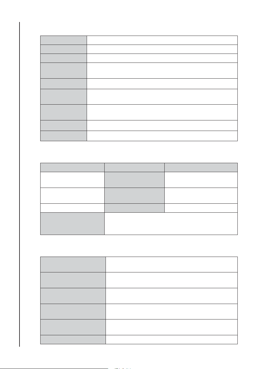
17.3 General
Supply voltage 100 to 240V ~ 50-60Hz.
Fuse Type T1AH 250V
Power input 3-80 VA
USB Connector : Mini Type: 1, full speed, 12 Mbps.
Specifi cations
Printer Integral 58 mm, thermal
Paper Roll width : 2.25” (58mm) nominal,
Size Height 6.3” (160mm), Depth 10.2” (240mm), Width 10.3”
Weight 6.6 lbs (3Kg)
Service Life 7 years
17.4 Environmental
Operating Storage
50°F to 95°F
(10°C to 35°C)
10% to 90% (non
condensing)
860mb to 1060mb Pressure 860mb to 1060mb
Paper Shelf Life Up to 5 years if stored in the original wrapping in a
Safety : Fully isolated
Roll diameter : 1.6” (40mm)
(260mm)
Temperature range -4°F to 122 °F
(-20°C to 50°C)
Relative Humidity 10% to 90% (non
condensing)
dark place at an approximate relative humidity of
50% and a temperature below 77°F (25°C).
17.5 Standards Compliance
IEC60601-1: 2005 Medical Electrical Equipment Part 1
EN60601-1-2: 2001
[collateral standard]
EN10993-1: 2009 &
AC: 2010
EN62366 :2008 General requirements for basic safety and essential
IEC 62304: 2006 Medical device software - Software life cycle
46
BS EN 980:2008 Symbols for use in the labelling of medical devices
General Requirements for Safety
General requirements for safety: Electromagnetic
compatibility
Biological Evaluation of Medical Devices; Guidance
on selection of tests
performance - Collateral standard: Usability
processes.
Page 47
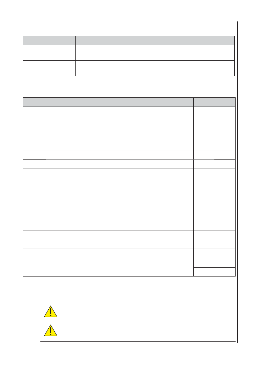
17.6 Batteries
Chemistry Voltage Compliance Part No
Rechargeable
Battery pack
Real time clock
back up battery
NiMH 12V UL2054 SP-771332
Lithium Manganese
Dioxide
3V SP-771514
17.7 Accessories
Item Part No.
Roll Stand* with integrated storage basket and tube management
(a)
Wall Mount with optional storage basket and tube management (b) ACC-VSM-154
Utility Hook (for wall mount) (c) ACC-VSM-187
Fixing plate** (d) ACC-VAS-012
Carry Bag ACC-VAS-015
Adult Cuff Set - arm and ankle cuffs ACC-VAS-027
Adult Right Arm Cuff - 8.5”-14” (22-36cm) ACC-VAS-023
Adult Right Ankle Cuff - 7”-11” (18-28cm) ACC-VAS-024
Adult Left Arm Cuff - 8.5”-14” (22-36cm) ACC-VAS-025
Adult Left Ankle Cuff - 7”-11” (18-28cm) ACC-VAS-026
Large Adult Cuff Set - arm and ankle cuffs ACC-VAS-011
Large Adult Right Arm Cuff - 13”-18” (34-46cm) ACC-VAS-007
Large Adult Right Ankle Cuff - 9.5”-14” (24-35cm) ACC-VAS-008
Large Adult Left Arm Cuff - 13”-18” (34-46cm) ACC-VAS-009
Large Adult Left Ankle Cuff - 9.5”-14” (24-35cm) ACC-VAS-010
Infection Control Barrier Sleeves (Disposable, box of 100) ACC-VAS-016
Printer
Paper
Standard Thermal Paper (Pack 5)
Adhesive Backed Thermal Label Paper (Pack 5)
ACC-VAS-013
ACC-VAS-017
ACC-VAS-019
Specifi cations
(a) + (d) - Items must be purchased together
(b) + (c) + (d) - Items must be purchased together
*Do not use dopplex Ability with other non-approved
accessories.
**Always use the Fixing plate when attaching the dopplex Ability
to approved accessories.
47
Page 48
18. Electromagnetic Compatibility
Make sure the environment in which dopplex Ability is installed is not subject to
strong sources of electromagnetic interference (e.g. radio transmitters, mobile
phones).
This equipment generates and uses radio frequency energy. If not installed
and used properly, in strict accordance with the manufacturer’s instructions,
it may cause or be subject to interference. Type-tested in a fully confi gured
system, complies with IEC60601-1-2, the standard intended to provide
reasonable protection against such interference. Whether the equipment causes
interference may be determined by turning the equipment off and on. If it does
cause or is affected by interference, one or more of the following measures may
correct the interference:
• Reorienting the equipment
• Relocating the equipment with respect to the source of interference
• Moving the equipment away from the device with which it is
interfering
• Plugging the equipment into a different outlet so that the devices are
Electromagnetic Compatibility
on different branch circuits
WARNING: The use of accessories, transducers and cables other
than those specifi ed, with the exception of transducers and cables
sold by the manufacturer of the dopplex Ability as replacement
parts for internal components, may result in increased emissions
or decreased immunity of the dopplex Ability.
WARNING: The dopplex Ability should not be used adjacent to
or stacked with other equipment and that if adjacent or stacked
use is necessary, the dopplex Ability should be observed to verify
normal operation in the confi guration in which it will be used .
48
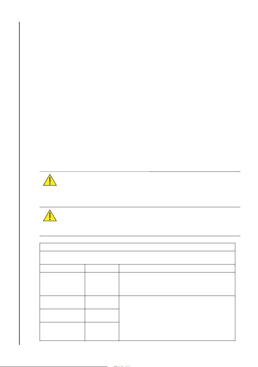
Guidance and Manufacturer’s declaration - electromagnetic emissions
The dopplex Ability is intended for use in the electromagnetic environment specifi ed below. The
customer or the user of the dopplex Ability should assure that it is used in such an environment.
Emissions Test Compliance Electromagnetic Environment - guidance
RF emissions
CISPR 11
RF emissions
CISPR 11
Harmonic emissions
IEC 61000-3-2
Voltage fl uctuations /
fl icker emissions
IEC 61000-3-3
Group 1
Class B
Class A
Complies
The dopplex Ability uses RF energy only for its internal
function. Therefore, its RF emissions are very low and are
not likely to cause any interference in nearby electronic
equipment.
The dopplex Ability is suitable for use in all
establishments, including domestic establishments and
those directly connected to the public low-voltage power
supply network that supplies buildings used for domestic
purposes.
Page 49
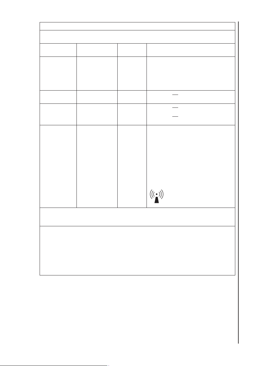
Guidance and Manufacturer’s declaration - electromagnetic immunity
The dopplex Ability is intended for use in the electromagnetic environment specifi ed below. The
customer or the user of the dopplex Ability should assure that it is used in such an environment.
Immunity Test
Conducted RF
IEC 61000-4-6
Radiated RF
IEC 61000-4-3
IEC 60601 test
level
3 Vrms
150kHz to 80MHz
3 V/m
80MHz to 2.5MHz
Compliance
level
3V
3V/m
Electromagnetic Environment - guidance
Portable and mobile RF communications
equipment should be used no closer to any
part of the dopplex Ability, including cables,
than the recommended separation distance
calculated from the equation applicable to
the frequency of the transmitter.
d = 1.2 √ P
d = 1.2 √ P
d = 2.3 √ P
where P is the maximum output power
rating of the transmitter in watts (W)
according to the transmitter manufacturer
and d is the recommended separation
distance in metres (m).
Field strengths from fi xed RF transmitters,
as determined by an electromagnetic
site survey, a should be less than the
compliance level in each frequency range b.
Interference may occur in the vicinity of
the equipment marked with the following
symbol:
80MHz to 800MHz
800MHz to 2.5GHz
Electromagnetic Compatibility
NOTE 1 At 80MHz and 800MHz, the higher frequency range applies.
NOTE 2 These guidelines may not apply in all situations. Electromagnetic propagation is affected
by absorption and refl ection from structures, objects and people.
a
Field strengths from fi xed transmitters, such as base stations for radio (cellular/cordless)
telephones and land mobile radios, amateur radio, AM and FM radio broadcast and TV broadcast
cannot be predicted theoretically with accuracy. To assess the electromagnetic environment due to
fi xed RF transmitters, an electromagnetic site survey should be considered. If the measured fi eld
strength in the location in which the dopplex Ability is used exceeds the applicable RF compliance
level above, the dopplex Ability should be observed to verify normal operation. If abnormal
performance is observed, additional measures may be necessary, such as re-orienting or relocating
the dopplex Ability.
b
Over the frequency range 150kHz to 80kHz, fi eld strengths should be less than 3V/m.
49
Page 50

Electromagnetic Compatibility
Guidance and Manufacturer’s declaration - electromagnetic immunity
The Dopplex Ability is intended for use in the electromagnetic environment specifi ed below. The
customer or the user of the Dopplex Ability should assure that it is used in such an environment.
Immunity Test
Electrostatic discharge
(ESD)
IEC 61000-4-2
IEC 60601 test
level
± 6 kV contact
± 8 kV air
Compliance
level
± 6 kV contact
± 8 kV air
Electromagnetic Environment
- guidance
Floors should be wood, concrete
or ceramic tile. If fl oors are
covered with synthetic material,
the relative humidity should be at
least 30%.
Electrical fast transient
burst
± 2 kV for power
supply lines
± 2 kV for power
supply lines
Mains power quality should be
that of a typical commercial or
hospital environment.
IEC 61000-4-4
Surge
IEC 61000-4-5
Voltage dips, short
interruptions and
voltage variations on
power supply input
lines
IEC 61000-4-11
± 1 kV for input/
output lines
± 1 kV line(s) to
line(s)
± 2 kV line(s) to
earth
<5 % U
r
(>95 % dip in Ur )
for 0,5 cycles
40 % U
r
(60 % dip in Ur )
for 5 cycles
± 1 kV for input/
output lines
± 1 kV line(s) to
line(s)
± 2 kV line(s) to
earth
<5 % U
r
(>95 % dip in Ur )
for 0,5 cycles
40 % U
r
(60 % dip in Ur )
for 5 cycles
Mains power quality should be
that of a typical commercial or
hospital environment.
Mains power quality should be
that of a typical commercial of
hospital environment. If the user
of the Dopplex Ability requires
continued operation during
power mains interruptions, it is
recommended that the Dopplex
Ability is powered from an
Power frequency
(50/60Hz) magnetic
fi eld
70 % U
r
(30 % dip in Ur )
for 25 cycles
<5 % U
r
(>95 % dip in Ur )
for 5 s
3 A/m 3 A/m Power frequency magnetic fi elds
70 % U
r
(30 % dip in Ur )
for 25 cycles
<5 % U
r
(>95 % dip in Ur )
for 5 s
uninterruptible power supply or
battery.
should be at levels characteristic
of a typical location in a
typical commercial or hospital
IEC 61000-4-8
is the a.c. mains voltage prior to the application of the test level.
NOTE U
r
environment.
50
Page 51

Recommended separation distances between portable and mobile RF communications
The dopplex Ability is intended for use in an electromagnetic environment in which radiated
RF disturbances are controlled. the customer or user of the dopplex Ability can help prevent
electromagnetic interference by maintaining a minimum distance between portable and mobile
RF communications equipment (transmitters) and the dopplex Ability as recommended below,
according to the maximum output power of the communications equipment.
Rated maximum
output power of
transmitter
W
0.01 0.12 0.12 0.23
0.1 0.38 0.38 0.73
1 1.2 1.2 2.3
10 3.8 3.8 7.3
100 12 12 23
For transmitters rated at a maximum output power not listed above, the recommended separation
distance d in metres (m) can be estimated using the equation applicable to the frequency of the
transmitter, where P is the maximum output power rating of the transmitter in watts (W) according to
the transmitter manufacturer.
NOTE 1 At 80MHz and 800MHz, the separation distance for the higher frequency range applies.
NOTE 2 These guidelines may not apply in all situations. Electromagnetic propagation is affected
by absorption and refl ection from structures, objects and people.
equipment and the dopplex Ability
Separation distance according to frequency of transmitter
150kHz to 80MHz
d = 1.2 √ P
80MHz to 800MHz
m
800MHz to 2.5GHz
d = 1.2 √ P
d = 2.3 √ P
Electromagnetic Compatibility
18.1 Electrostatic Discharge
Electrostatic discharge (ESD) is a known problem that can affect electrical
equipment. If the dopplex Ability is subjected to ESD during an ABI
measurement, it is possible that the measurement will be suspended. The air in
all cuff chambers will be rapidly exhausted, and the unit will reset to the start-up
screen.
If this happens, simply perform the usual checks and repeat the test.
51
Page 52

19. End of Life Disposal
End of Life Disposal
This symbol signifi es that this product, including its accessories and
consumables is subject to the WEEE (Waste Electrical and Electronic
Equipment) regulations and should be disposed of responsibly in accordance
with local procedures.
52
Page 53

20. Warranty & Service
a) ARJOHUNTLEIGH INC. HEREBY DISCLAIMS ALL EXPRESS OR IMPLIED
WARRANTIES (INCLUDING BUT NOT LIMITED TO WARRANTIES OF MERCHANTABILITY OR
FITNESS FOR A PARTICULAR PURPOSE) AND ANY AGREEMENTS, REPRESENTA TIONS,
AFFIRMATIONS, OR WARRANTIES, WHETHER ORAL OR WRITTEN, MADE BY ANY AGENT,
EMPLOYEE OR REPRESENTATIVE OF ARJOHUNTLEIGH INC., UNLESS SPECIFICALLY SET
FORTH IN THIS PARAGRAPH. ARJOHUNTLEIGH INC. SHALL NOT BE LIABLE FOR BREACH
OF CONTRACT ARISING FROM ANY DEFECT IN MATERIAL OR WORKMANSHIP OF THE
GOODS. ALL LEGISLATION RELATING TO EXPRESS AND IMPLIED WARRANTIES OR
OTHER OBLIGATIONS ON THE PART OF ARJOHUNTLEIGH INC. THAT MAY BE LAWFULLY
EXCLUDED ARE HEREBY EXCLUDED.
b) Notwithstanding the foregoing, ArjoHuntleigh Inc.’s sole warranty is that the Goods shall
be free from defects in material and workmanship for a period of one (1) year, following delivery
of such Goods to the original purchaser; provided that the Goods were used in an appropriate
and reasonable manner during such period and provided further that ArjoHuntleigh Inc. shall be
in no event be liable to Customer for defective Goods if: (i) the Goods are damaged in the course
of shipping; (ii) any defect is caused wholly or to any material extent by customer’s negligence,
misuse, failure to use the Goods properly or use of the Goods in conjunction with any accessory
not approved for use with the Goods by ArjoHuntleigh Inc.; (iii) the Goods are damaged as a result
of improper maintenance, failure to follow manufacturer’s instructions, including without limitation
those on washing and cleaning, or failure to follow necessary routine maintenance procedures;
or (iv) the Goods are altered, repaired or dismantled other than with manufacturer’s written
authorization using its approved procedures or by any party other than manufacturer’s properly
qualifi ed and trained technicians.
c) Customer must provide written notice to ArjoHuntleigh Inc., within said warranty period
of any defect in the Goods. Upon ArjoHuntleigh Inc.’s written request, Customer must return such
Goods adequately packed (in their original packing) and fully insured to ArjoHuntleigh Inc.#’s
place of business and shall be responsible for all shipping costs incurred therein.
Customer’s exclusive remedy and ArjoHuntleigh Inc.’s exclusive liability for any claim for loss,
damage or destruction resulting from any defects in materials and workmanship shall be limited to
repair, service, adjustment or replacement (at ArjoHuntleigh Inc.’s option) of any nonconforming or
defective Goods. ArjoHuntleigh Inc. will have a reasonable time to repair, service or replace such
Goods. Any Goods returned to ArjoHuntleigh Inc. which are found not to be defective in breach of
the warranty in Subsection (b) above, shall be returned to the Customer in the manner described
in this subsection.
Warranty & Service
d) IN NO EVENT SHALL ARJOHUNTLEIGH INC. BE LIABLE FOR ANY INCIDENTAL OR
CONSEQUENTIAL LOSSES OR DAMAGES (INCLUDING BUT NOT LIMITED TO ECONOMIC
LOSS, LOSS OF PROFITS OR SPECIAL DAMAGES) ARISING OUT OF OR INCURRED BY
CUSTOMER IN CONNECTION WITH THE PURCHASE OF ARJOHUNTLEIGH INC.’S GOODS
EVEN IF ARJOHUNTLEIGH INC. HAS BEEN ADVISED OR HAS KNOWLEDGE OF THE
POSSIBILITY OR EXTENT OF SUCH DAMAGES SUFFERED OR INCURRED BY CUSTOMER
OR ANY END USER AS A RESULT OF OR IN CONNECTION WITH ANY BREACH OF THESE
TERMS AND CONDITIONS BY ARJOHUNTLEIGH INC. OR ANY TORT (INCLUDING BUT NOT
LIMITED TO STRICT LIABILITY OR NEGLIGENCE) COMMITTED BY ARJOHUNTLEIGH
INC., ITS AGENTS OR REPRESENTATIVES IN CONNECTION WITH THESE TERMS AND
CONDITIONS OR ANY CONTRACT WITH CUSTOMER FOR THE SUPPLY OF GOODS.
53
Page 54

Warranty & Service
e) Customer shall not create, directly or indirectly, any warranty obligations on the part
of ArjoHuntleigh Inc. to the customers of Customer, and in particular, without limiting the
foregoing, Customer agrees not to pass on to its customers any warranties beyond or in
addition to those given by ArjoHuntleigh Inc. to Customer hereunder. Where the Customer
is a dealer in the Goods, it shall be responsible for the labor cost of all repairs and
ArjoHuntleigh Inc. shall be responsible for providing all repair parts during said one (1)
year. The dealer shall provide written verifi cation of warranty repairs including the original
invoice number, date of purchase, description of repairs, name of its customer and date of
sale to such customer.
f) Customer shall be deemed to have full knowledge of the nature and properties of
the Goods ordered and of any hazards they involve and the proper treatment, storage
and handling thereof. Any technical advice furnished by ArjoHuntleigh Inc. or its
representatives or agents is given only on the basis that it is followed at the Customer’s
own risk
Service Returns
If for any reason the dopplex Ability has to be returned, please:
• Clean the product following the instructions in this manual.
• Pack it in suitable packing.
• Attach a decontamination certifi cate (or other statement declaring
that the product has been cleaned) to the outside of the package.
• Call Huntleigh Service Dept. in San Antonio, TX for a return
authorization number.
54
Huntleigh Healthcare Ltd reserve the right to return product that does not
contain a decontamination certifi cate.
Page 55

© Huntleigh Healthcare Ltd
All rights reserved
The dopplex Ability is in conformity with the Medical Devices Directive
93/42/EEC as amended by 2007/47/EC and has been subject to the
conformity assurance procedures laid down by the Council Directive
Manufactured in the UK by Huntleigh Healthcare Ltd.
As part of the ongoing development programme the company reserves the right
to modify specifi cations and materials without notice.
Dopplex, Ability and Huntleigh are registered trademarks of Huntleigh
Technology Ltd. 2011.
© Huntleigh Healthcare Ltd. 2011
Page 56

201
1
771528-4
(ENGLISH - USA)
 Loading...