

Page 1

CONTENTS
Subject
Contents 1
Ilustrations 1
Limited Warranty on Seal Image Laminators 2
Introduction 3
Using this Manual 3
Features and Benefits 3
Safety Features and Benefits 4
Safety and Warranty Instructions 4
Environment 5
Safety Symbols 5
Specifications 6
Identification 6
Installation, Uncrating and Moving 7
Control Panel 8,9
Checking Operation 10
Preset Programs 11,12
Loading Film 13
Unwind Brakes 14
Roller Nip Settings 14
Encapsulation 15
Decaling 16
Mounting 17
One Step Mounting and Laminating 18
Face Mounting 19
Pre-Coating a Substrate 20
Applying Overlaminate 21
Cleaning and Maintenance 22
Technical Assistance 22
Trouble Shooting 22,23
Location of Breakers 23
Error Codes 24
Electrical Diagrams 25,26
Replacement Parts and Accessories 27
Glossary 28
For More Information 29
Page
ILLUSTRATIONS
Subject
Loading Film 13
Encapsulation 15
Decaling 16
Mounting 17
One Step Mounting and Laminating 18
Face Mounting 19
Pre-Coating a Substrate 20
Applying Overlaminate 21
Page
- 1 - H
Page 2

Limited Warranty on Seal Image Laminators
Hunt Graphics warrant to the original consumer
purchaser *that all new Image® laminators which prove
defective in materials or workmanship, within the
applicable warranty period will be repaired, or, at our
option, replaced without charge. The applicable warranty
shall be one year from the date of purchase, with the
exception of silicone roll coverings. Silicone roll coverings
will be under warranty six months from the date of
purchase. (12 months in a row.)
*“Original consumer purchaser” is the person who first
purchased the laminator. If the laminator does not remain
in the possession of the original consumer purchaser, the
warranty will be invalid.
For more information regarding this warranty, please
contact your distributor.
* Warning! Changes or modifications to this unit not
expressly approved by the party responsible for
compliance could void the user’s authority to operate the
equipment.
* Warning! This machine is designed for mounting and
laminating. Any use other than the intended may cause
damage to the machine or physical harm to the user.
* Warning! Any unauthorized changes or
modifications to this unit will void the user warranty and
transfer health and safety obligations to the user.
- 2 - 3 H
Page 3

INTRODUCTION
USING THIS MANUAL
Thank you for purchasing the Image®410 laminator, a
laminator designed to give you years of reliable service.
The Image®410 brings a new level of simplicity and ease
of use to image finishing.
Reading your Owners Manual will familiarize you with the
operational features and guidelines of your laminator.
This manual contains instructions on various laminating
techniques and diagrams that give you the
comprehensive information needed for safe and efficient
use of your laminator. This knowledge provides the
foundation for innovative uses and creativity you can
achieve through basic skill and practice. Once you have
used the Image® 410 laminator, you will understand
exactly why it is of the highest quality in design and
manufacture available.
Special Markings
Warning! Please pay attention to all passages marked
this way *. This information is vital to the proper use of
and maintenance of the laminator and to the safety of its
users.
FEATURES AND BENEFITS OF THE IMAGE® 410
n High release silicone rollers prevent adhesive build up
and make cleaning easy.
n Digital touch pad control panel with LED indicators. It
allows the operator to use 9 preset heat and motor
speed settings to match film applications. The
operator can also customize these settings.
n Pivoting Auto Grip Unwind Shafts make film switches
quicker and easier.
n Motor driven roller height adjustment allows for
accurate roller nip setting with no need for an air
compressor.
n The footswitch runs the laminator in slow mode at 2.0
feet or 0.6 meters per minute.
- 3 - 3 H
Page 4

SAFETY FEATURES AND BENEFITS
The Image® 410 is one of the safest laminators on the
market.
n The side plate covers can be opened only with an
Allen wrench, this should be done by an authorized
Service Technician.
n Photoelectric Safety Eyes prevent foreign objects
from passing between the main rollers. When a
photoelectric eye is blocked, the laminator rollers
stop.
n Emergency Stop Buttons are located on both sides of
the machine. The emergency stop buttons shut down
all power to the machine and raise the rollers. They
should only be used in case of an emergency. Once
pressed, the buttons lock and need to be turned
clockwise to reset. Thereafter, the power button must
also be turned on. If the emergency stop is
depressed, the machine will default to program 1
upon restart.
n Covered footswitch prevents accidental activation of
roller movement. It can be used to give the operator
control when feeding an image through the machine.
n Buzzer and Flashing Light warns the operator if
fingers are getting too close to the nip while using the
footswitch.
n Infeed Table has a channel to allow for easy media
feeding while keeping fingers a safe distance from the
main rolls.
n Enclosed pull system prevents foreign objects from
passing between the rollers.
n Power Disconnect Switch is located on the left side
leg. When turned to the off position, will shut off the
laminator.
SAFETY AND WARRANTY INSTRUCTIONS
n Read all safety and operating instructions before
operating the machine.
n Adhere to all warnings on the machine and in the
manual.
n Follow all operating and user instructions.
n Operate the machine with the type of power sources
indicated in this manual.
n Refer all servicing to an authorized service
representative. Servicing by any unauthorized
technician voids the warranty.
n Hunt Graphics must specify replacement parts.
n Service Technicians must perform safety checks after
completing any service or repair.
n Use only enclosed knife cutters around the machine.
n Never cut or slice directly on the rollers.
n Keep all objects such as tools, pens, etc. away from
the roller opening.
n Do not wear loose garments or loose jewelry while
operating the laminator.
* Warning! When the laminator is not in use, adjust
the nip gap to at least 3/16” (setting 5). This will prevent
flat spots from developing on the main rolls. Flat spots
will effect the quality of the output and void warranty.
* Warning! When the laminator is not in use, or while
rollers are heating up, pivot the front table away from the
rollers. This will prevent the front table from possible
distortion. Warranty will not cover distorted tables.
- 4 - 3 H
Page 5
* Warning! Authorized service technicians must
disconnect the power by using the power disconnect
(located on the left side stand leg) before any servicing.
ENVIRONMENT
n Position your laminator in a clean dust free
environment to ensure high quality output.
n Operation of a laminator near water or in an area of
high humidity requires installation of a GFI breaker.
SAFETY SYMBOLS
WARNINGS:
These warning symbols are located on the machine.
Use extreme caution in areas identified by these
symbols.
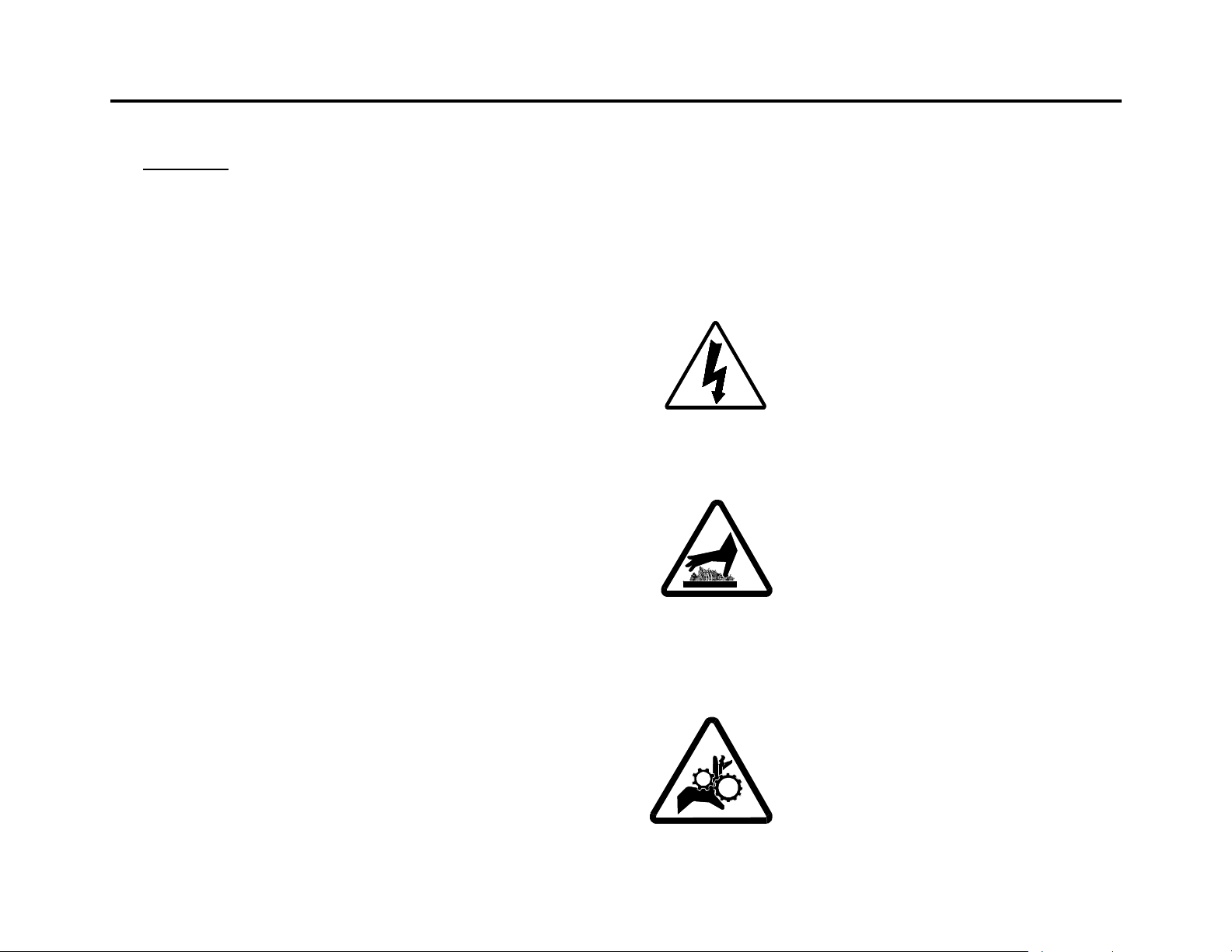
Electrical Parts – Electrical hazard
inside! Located on the back of the
side plates, near the bottom bolts
that attach the covers.
Hot Surfaces - Danger of burns
upon skin contact! Located near
the rollers.
Rotating Parts - Pinch Point,
danger of getting hands or arms
caught between! Located near the
rollers.
- 5 - 3 H
Page 6
SPECIFICATIONS
IDENTIFICATION
Maximum Working Width 43” (110 cm)
Maximum Heated Width 45.5” (115.6 cm)
Maximum Speed 10 ft./min
(304.8 cm/min)
Maximum Main Roll
Temperature
Maximum Roller Opening 1.125” (2.86cm)
Maximum Substrate
Thickness
Roller Construction High Release Silicone
Supply Shaft Capacity
(Core inner Diameter)
Maximum Material Outside
Diameter
Dimensions Width: 62” (1,575mm)
Net Weight 610 lbs. (277 Kg)
Shipping Weight 860 lbs. (391 Kg)
Electrical Requirements 200-240 VAC
Maximum Power
Consumption
Air Borne Noise Less than 70 DB(A)
250° F (121°C)
1” (2.54cm)
I.D.:3” (7.6cm)
O.D.: 8” (20.32cm)
Depth: 30” (762 mm)
Height: 46.6”(1,184mm)
50-60HZ Single Phase
16A
3840 Watts
12,065 BTU
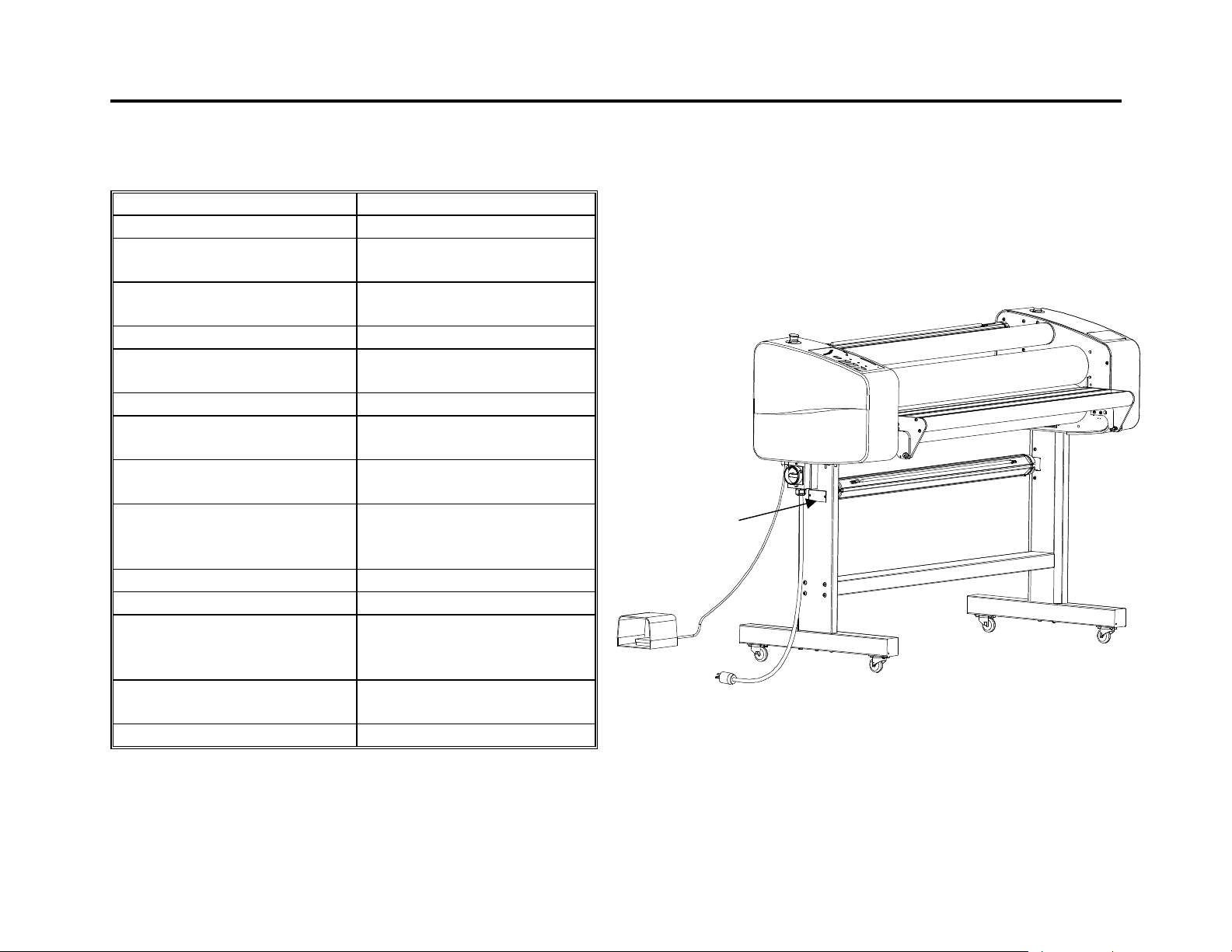
The Identification Plate details manufacturing information
and European CE mark. Refer below to diagram for
location.
- 6 - 3 H
Page 7

INSTALLATION, UNCRATING AND MOVING THE
IMAGE® 410
Seal recommends that a licensed electrician in
accordance with electrical codes in your area install
power for your laminator. Refer to the Specifications
table. Please fill out the Installation Acceptance sheet
found in your accessory pack and return to Hunt
Graphics. (U.S. only)
Please keep your shipping bolts, nuts, and plates for
possible future moves.
Your laminator is equipped with castors that allow ease in
movement. Fix your laminator in an area with adequate
space. You will need room to feed, receive, and trim
images. Once your laminator is in place, lock the
castors. Always unlock the castors before moving your
laminator.
Place the footswitch in a position that is accessible while
feeding images.
Remove wrapping from the rolls.
* Warning! Do not use sharp objects to remove the
paper from the rolls.
Plug the laminator into the recommended electrical
outlet.
Push the power button. If you have no power, refer to
Troubleshooting, pages 22,23.
- 7 - 3 H
Page 8
11
14
12
15
CONTROL PANEL
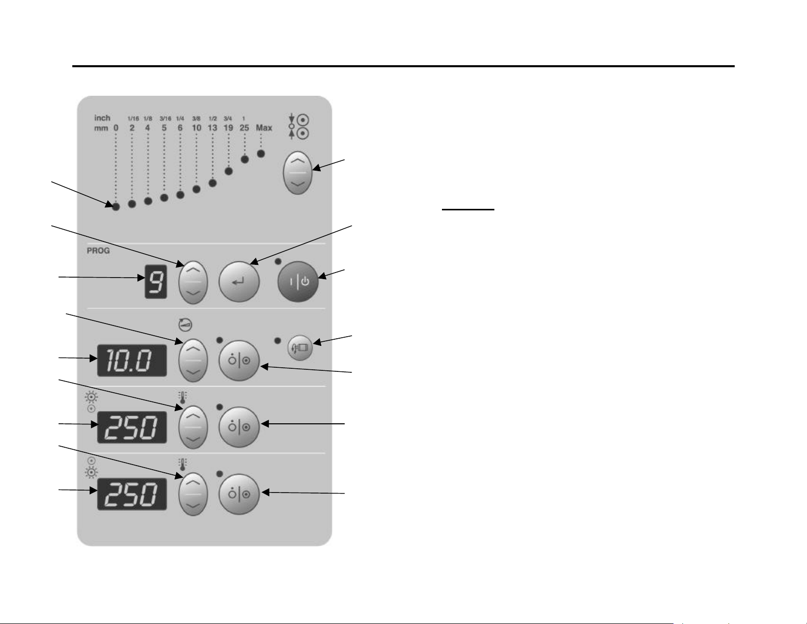
1. Power Standby Button turns the power on and off. If
an emergency stop is depressed to cease operation,
the emergency stop button must be reset. Then the
power switch can be depressed to begin operation.
n Power Indicator Light is on when the laminator is on.
* Warning! Even when the power is off the laminator
is on Standby. Authorized Service Technicians must
unplug the laminator before any servicing.
13
4
5
10
8
7
1
2. Motor Button turns the motor on and off. While the
motor is off the footswitch may be utilized. The
footswitch runs in slow mode at 2 feet or .6 meters
per minute.
3
16
3. Motor Speed Buttons increase or decrease the speed
of the motor.
4. Motor Speed readout indicates speed in feet per
minute or meters per minute.
2
n Motor Indicator Light is lit when motor is on.
5. Top Heater Temperature readout indicates the
current temperature of the top main roll.
6
6. Top Heater Power Button turns the top heater on or
off.
n Top Heater Indicator Light is lit when top heater is on.
7. Top Heater Temperature Adjust Button.
n Push either arrow (up or down) once to see top
9
temperature set point. Push and hold either arrow to
raise or lower temperature.
8. Bottom Heater Temperature Readout indicates the
current temperature of the bottom main roll.
9. Bottom Heater Power Button turns the bottom heater
on or off.
- 8 - 3 H
Page 9

n Bottom Heater Indicator Light is lit when bottom
heater is on.
10. Bottom Heater Temperature Adjust Button.
n Push either arrow (up or down) once to see top
temperature set point. Push and hold either arrow to
raise or lower temperature.
11. Nip Indicator Lights indicate which nip setting the
rolls are currently set at.
12. Nip Adjustment Button.
n Up Arrow push once to raise one setting. Push and
hold to raise multiple settings.
n Nip Adjustment Button down Arrow push once to
lower one setting. Push and hold to lower multiple
settings.
13. Program Readout indicates which program is
currently available.
14. Program Select Button. (Choose a preset program)
n Push up or down arrow once to see current program
settings. (Speed and Temperature Readouts). Push
and hold up or down arrow to raise or lower
numbered program.
15. Program Enter Button (This button has two
functions.)
Function A
n Push and release to load shown program (See item
#13).
Function B
n To program a new preset, First choose the program #
you want to set (1-9).
Set the heat and motor speeds to how you want the
program to recall them. Push and hold button 15.
The screen will go blank (approximately three
seconds), and then the program will appear on the
display. Release the button.
Note: After a program has been loaded, the operator
can still change heat and speed settings with their
respective up and down arrows.
16. Reverse Mode Button reverses the direction of the
rollers.
n The Reverse Mode Button may be utilized only when
the motor is off.
n Push the Reverse Mode Button.
n Reverse Mode Indicator light is on.
n Depress the footswitch to activate the reverse roller
movement.
n Motor Indicator light is lit while depressing the
footswitch.
n The rollers will reverse at 1 ft./min. (.3M). The speed
cannot be adjusted.
To return to forward roller movement:
n With the footswitch inactive, push the Reverse Mode
Button (Reverse Mode Indicator light will be off).
n Push the Motor Button (#2).
n Motor Indicator light is on.
- 9 - 3 H
Page 10

CHECKING OPERATION
After you are familiar with the control panel buttons,
check all operations.
Check the Rollers
n Push the Nip Adjustment up Arrow Button once. The
roller should move up smoothly and evenly on both
ends.
n Push the Nip Adjustment down Arrow once. The
roller should move down smoothly and evenly on both
ends.
Check the Motor and Footswitch
n Push the Motor Power Button once, the motor
indicator light should be lit. Push the Motor up
button. The Motor Speed should increase, and the
readout should increase in number.
n Push the Motor down button. The speed should
decrease, and the readout should decrease in
number.
Check the Photo-Eye System
n The safety photo-eye system should be checked
every 6 months (or after any internal adjustment /
repair) using a tool made from a piece of 12mm (1/2”)
diameter wood or similar material.
n To test the photo-eye system, place the tool on the
table and slowly move it towards the rotating roller.
The rotation must stop before the tool touches the
roller face.
n This test must be carried out across the whole width
of the table. If the photo-eye does not operate, switch
off the machine and do not use until it has been
adjusted and checked by an authorized service
technician.
Check the Heater Controls
n Push the top heater power button once. The Top
Heater Indicator light should be lit. Push the top
heater up button to see the top temperature set point.
Watch the Top heater temperature readout for five
minutes. The temperature should increase in
number. Push the top heater power button again.
The top heater indicator light should not be lit.
n Push the bottom heater power button once. The
bottom heater indicator light should be lit. Push the
bottom heater up button to see the bottom
temperature set point. Watch the bottom heater
temperature readout for five minutes. The
temperature should increase in number. Push the
bottom heater power button again. The bottom heater
indicator light should not be lit.
* Warning! When the rollers are heated the table may
get hot.
Check the Emergency Stop Buttons
n Press one of the Emergency Stop Buttons located on
the top of the left and right cabinet covers of the
machine. The laminator will shut down.
n Rotate the Emergency Stop Button clockwise to reset.
n Press the Power Standby Button. The laminator will
turn back on. Check to make sure that the Power
Indicator light is on.
n Repeat process with the second Emergency Stop
Button.
* Warning! If your machine does not operate correctly,
contact Technical Service immediately.
- 10 - 3 H
Page 11

PRESET PROGRAMS
When using a preset program, the temperature will
automatically activate.
Program 1: Flexible Displays (Encapsulating). Refer
to page 15 for webbing diagram. Flexible Displays are
created by encapsulating a print between two layers of
laminate.
n Settings provided are for optimal performance using
Seal’s Jet Guard Crystal Matte on the top roller and
Seal’s Jet Guard Gloss on the bottom roller.
Top Roll Temperature
Bottom Roll Temperature
95°C (200° F)
95°C (200° F)
Speed 3fpm 1mpm
Program 2: Pop-Up Displays. Refer to page 16 for
webbing diagram. Pop-Up Displays are created by
encapsulating a print between a hot laminate and a
backing film.
n Settings provided are for optimal performance using
Seal’s Jet Guard Deep Crystal on the top roller and
Seal’s Stoplight (220 or 370) on the bottom roller.
Top Roll Temperature
Bottom Roll Temperature
90°C (195°F)
100° C (210°F)
Speed 3fpm 1mpm
Program 3: Rigid Indoor Displays (Decaling). Refer to
page 16 for webbing diagram. Rigid Indoor Displays are
made by first creating a decal, by applying a laminating
film over the face of the print, and a pressure sensitive
adhesive to the back.
n Settings provided are for optimal performance using
Seal’s Jet Guard Crystal Matte on the top roller and
Seal’s Printmount One (Printmount “R”) on the
bottom roller.
Top Roll Temperature
90-95°C (205°F)
Bottom Roll Temperature Ambient 45°C (110°F)
Speed 3fpm 1mpm
Program 4: Rigid Backlit Displays. Refer to page 19
for webbing diagram. Rigid Backlit Displays are created
by face mounting an image to clear acrylic using an
optically clear pressure sensitive adhesive. Use the
laminator to coat the acrylic and mount the print.
n Settings provided are for optimal performance using
Seal’s Optimount on the top roller.
Top Roll Temperature
60°C (140°F)
Bottom roll Temperature Ambient 45°C (110°F)
Speed 3fpm 1mpm
- 11 - 3 H
Page 12

Program 5: Floor Graphics. Refer to page 16 for
webbing diagram. Floor Graphics are made by first
creating a decal. Apply a Floor Guard, a special non-slip
durable laminating film, to the face of the print and Floor
Grip 1, a permanent/removable pressure sensitive
adhesive, to the back. This can be done in one pass. Use
a hand roller or squeegee to apply the graphic to a clean
smooth floor.
n Settings provided are for optimal performance using
Seal’s Floor Guard on the top roller and Seal’s Floor
Grip 1 on the bottom roller.
Top Roll Temperature
Bottom Roll Temperature
95°C (200°F)
Ambient to 45°C (110°F)
Speed 3fpm 1mpm
Program 6: OnePass Display. Refer to page 17 for
mounting diagram. OnePass Displays are created by
taking a printable laminate and sealing it onto foam board
or a rigid board, using the laminator.
n Settings provided are for optimal performance using
Seal’s OnePass on the top roller.
Top Roll Temperature
Bottom Roll Temperature
110°C (230°F)
Ambient to 45°C (110°F)
Speed 0.5-1.0fpm 0.2-0.3mpm
Purchasers should individually determine, prior to use, the
suitability of each material for their specific purposes. Hunt
Graphics does not accept liability for risks associated with the
performance of materials in application.
- 12 - 3 H
Page 13
LOADING FILM
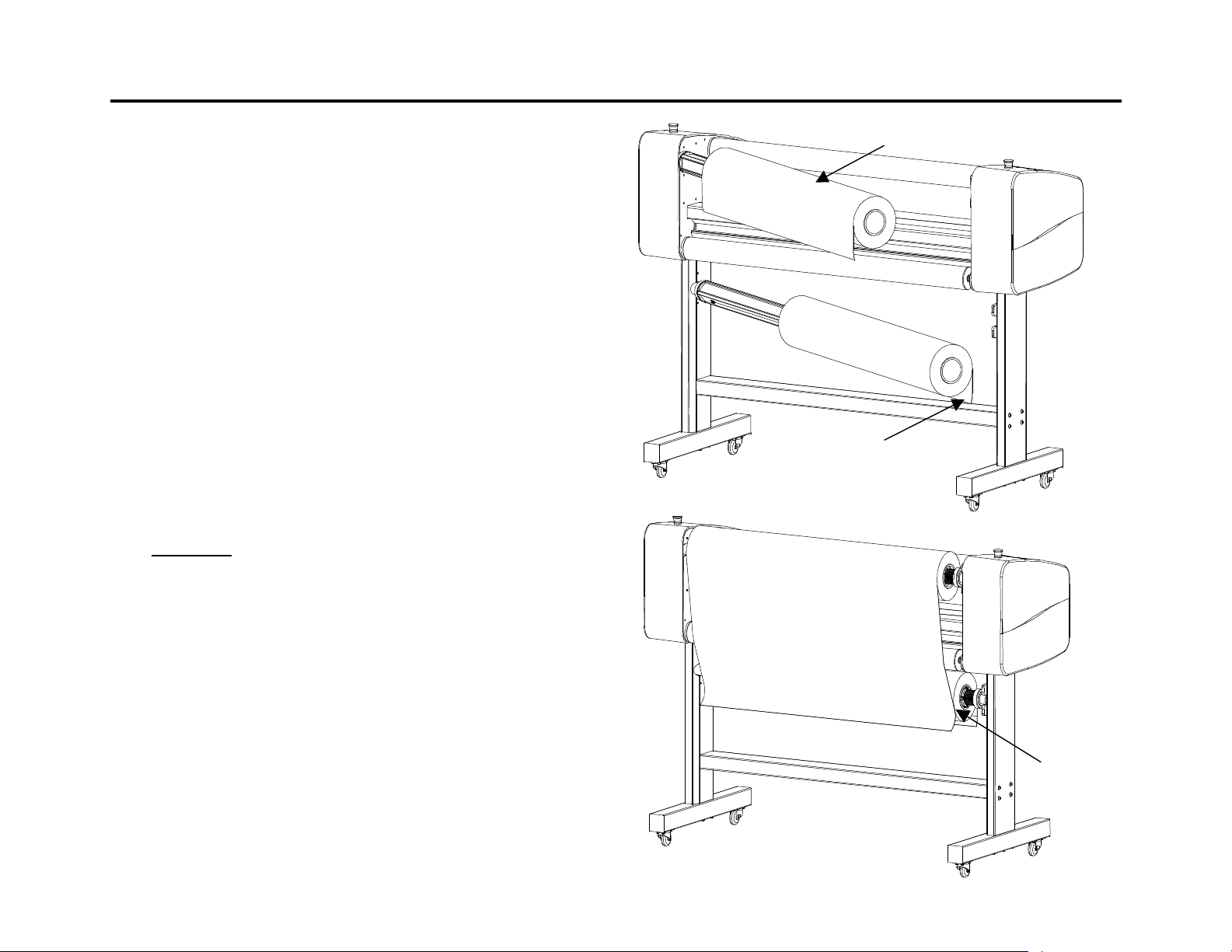
Each laminating/mounting procedure section, has web
diagrams depicting the correct way to load film.
Seal encapsulating films are wound with the adhesive
side on the inside, as in Figure A.
n The top and bottom unwind positions are to be loaded
as shown in Figure A.
n Center the rolls in relation to each other by unwinding
enough material from the top roller to reach the
bottom roll of film. Pull the film straight, then move
the bottom roll of film until the edges line up. See
figure B.
* Warning! If you choose to use a leader board to
push the film through the nips while webbing:
Laminate Side
Figure A
Adhesive Side
n Set the nip to the leader board thickness.
n After the board passes through the main rollers, you
Figure B
may set the nip to 0.
n Failure to do so will cause the machine to register an
error and shut down. To reset, use the door
disconnect.
Stretch film tight
and align edges.
- 13 - 3 H
Page 14
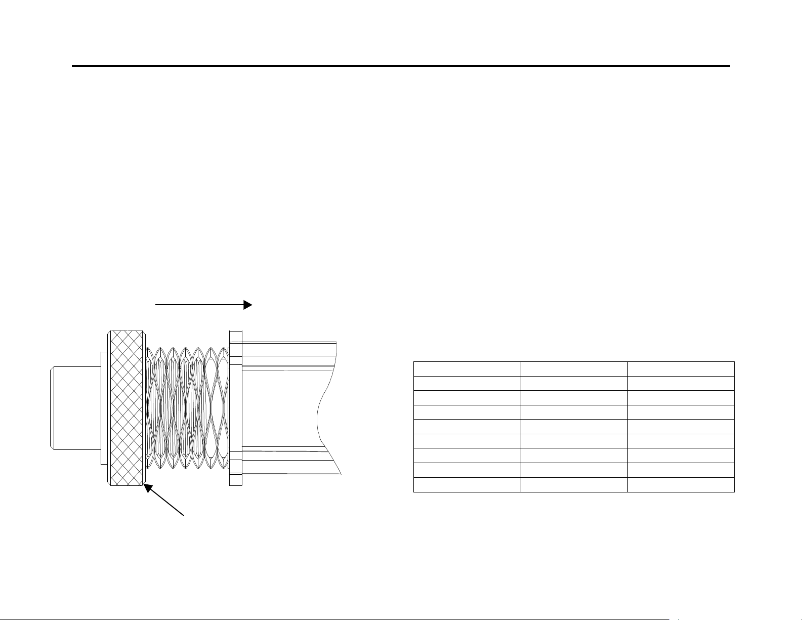
UNWIND BRAKES
Direction of compression
ROLLER NIP SETTINGS
The output of your film is greatly affected by the unwind
brakes. These are located on the autogrip unwind shafts.
How to set the brakes:
Tighten the knurled nut to compress the spring.
Compressing the spring will increase the film unwind
tension.
When using a substrate for mounting, it is important to
adjust the rollers to create a gap equal to the thickness of
the board being used. This will allow your material to
receive the correct amount of pressure and prevent
damage to the rollers.
How to set the Nip:
n Step one – Determine the thickness of the board that
you will use for mounting.
n Step two – Adjust the nip setting by pressing the??
buttons on the control panel to the same thickness
measured in step one.
Equivalent Measurements
Inches Metric (mm) Decimal
1/16 2 0.0625
1/8 3 0.125
3/16 5 0.1825
¼ 6 0.25
3/8 10 0.375
½ 13 0.5
¾ 19 0.75
1 25 1.00
- 14 - 3 H
Rotate to compress
Page 15
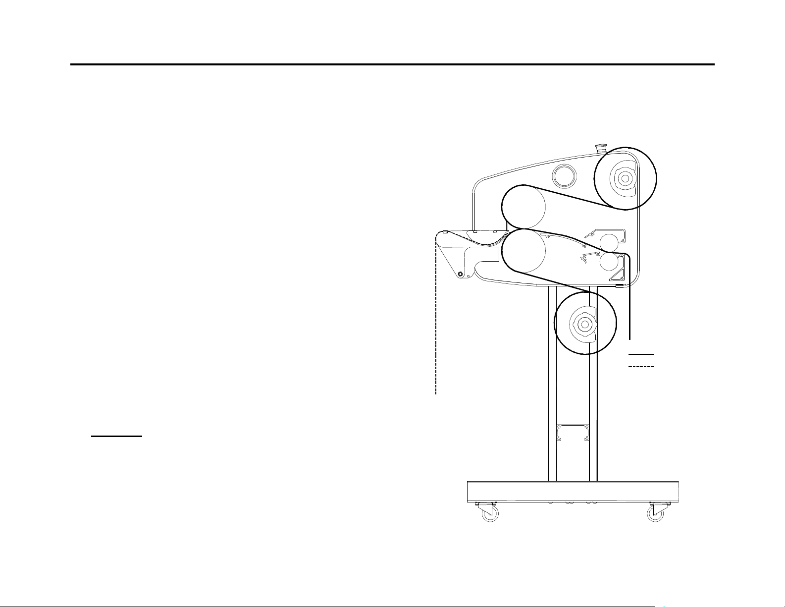
ENCAPSULATION
n Ensure that you have set the temperature of the
rollers according to the recommendations for the film
you are going to use.
The rollers should be stationary (Motor indicator light off).
Set your Nip to 0. Film should be loaded evenly on the
unwind shafts.
n Step one – The table should be pivoted into its lower
position. Pull the film down from the top unwind
position. Drape it across the face of the top and
bottom main rolls. The dull (adhesive) side should be
facing you.
n Step two – Pull the film from the bottom unwind
position up and over the top main roll. The top and
bottom films will heat and stick together.
n Step three - While the motor is off, use a piece of
leader board to push the films through the nip. Lower
the rollers. Press the footswitch and the rollers will
grab the film and pull it through.
n Step four - When the film reaches the chill shoe, cut
off the piece of leader board.
n Step six - Pivot the table up into its working position.
Feed your media into the table groove. Once into the
nip, apply a small amount of tension to the media.
Film Path
Media Path
* Warning! Do not cut or slice on the surface of the
chill shoe. This will affect the output of your images.
n Step five - Press the footswitch and feed the film into
the pull rollers. Apply brake tension to the unwind
shafts to remove wrinkles. Run the laminator for about
3 feet (1M), to work out any wrinkles. If wrinkles
persist cut the film and web the laminator again.
- 15 - 3 H
Page 16
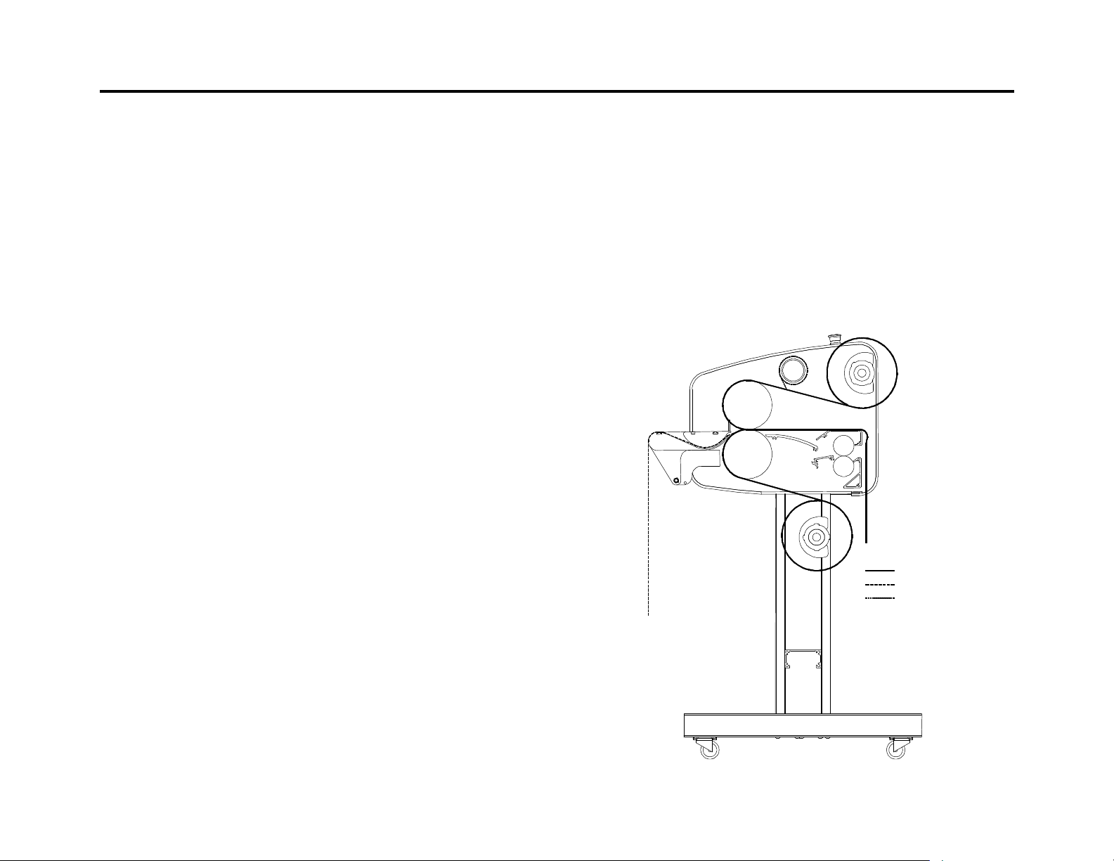
DECALING
This process involves applying a hot or cold laminate on
the face of the image and a pressure sensitive adhesive
on the back. This process is used to create self-adhesive
images for mounting on various substrates.
n Prepare the films that you will use on the top and
bottom of the images. It is advisable to use slightly
wider films in comparison to the print width. This will
allow you to trim the print and leave a border. Mount
the rolls onto the unwind shafts so the adhesive side
will not contact the rolls.
Webbing
n Step one - Pull the pressure sensitive adhesive from
the bottom unwind, around the front of the bottom
roller, and lay evenly across the top roller.
n Step two - If you are using film without a release
liner, pull the film down from the top unwind. Lay the
film down evenly over the rollers. If you are using
film with a release liner, pull the film down from the
top unwind. Separate the film from the release liner
and lay the film evenly over the face of the rollers.
The films will then stick together.
n Connect the release liner to the windup tube with a
piece of tape. Attaching the release liner to a
cardboard core (over the windup tube) will allow for
easier cleanup.
n Step three – Push the films into the main roller nip
using a leader board.
n Step four – Close the rollers and depress the
footswitch. Advance the leader board between the
rollers until it clears the back of the laminator. You
may now cut off the leader board. Do not use the
Pull rolls.
n Step five – Run the film and apply brake tension to
the unwind shafts to remove wrinkles. Run for
approximately 3 feet (1 M). If wrinkles persist cut the
film and web the laminator again.
n Step six – Feed your images.
Film Path
Media Path
Release Liner
- 16 - 3 H
Page 17
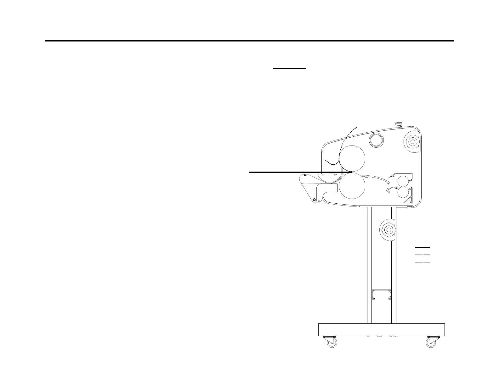
MOUNTING
This process involves mounting a decal onto a substrate.
No films or adhesives are used in this process.
n Adjust your nip setting to correspond with the
thickness of your substrate.
Procedure
n Step one - Place your substrate on a flat surface. Lay
your image face down on the substrate, peel back the
release liner along one of the edges, (approx. 1” or 25
mm exposed) and crease.
n Step two - Turn the image face up. Position the
image squarely on the substrate, be careful not to let
the exposed adhesive make contact.
n Step three - Once positioned correctly, press the
exposed adhesive firmly from the center out. This
edge will be fed into the rollers first.
n Step four - Push the bonded edge of the substrate
into the roller nip. Depress the footswitch, and be
careful not to allow the release liner to enter the nip.
n Step five – Flip the image over the top roller so that
the release liner can be peeled off. Hold the image
with slight tension against the top roller with one
hand. While depressing the footswitch, peel the
release liner away from the image.
* Warning! Take care that the release liner does not
trip the photo eyes.
Substrate
Decal
Release Liner
n Remove the mounted image from the rear of the
laminator and trim it if necessary.
- 17 - 3 H
Page 18
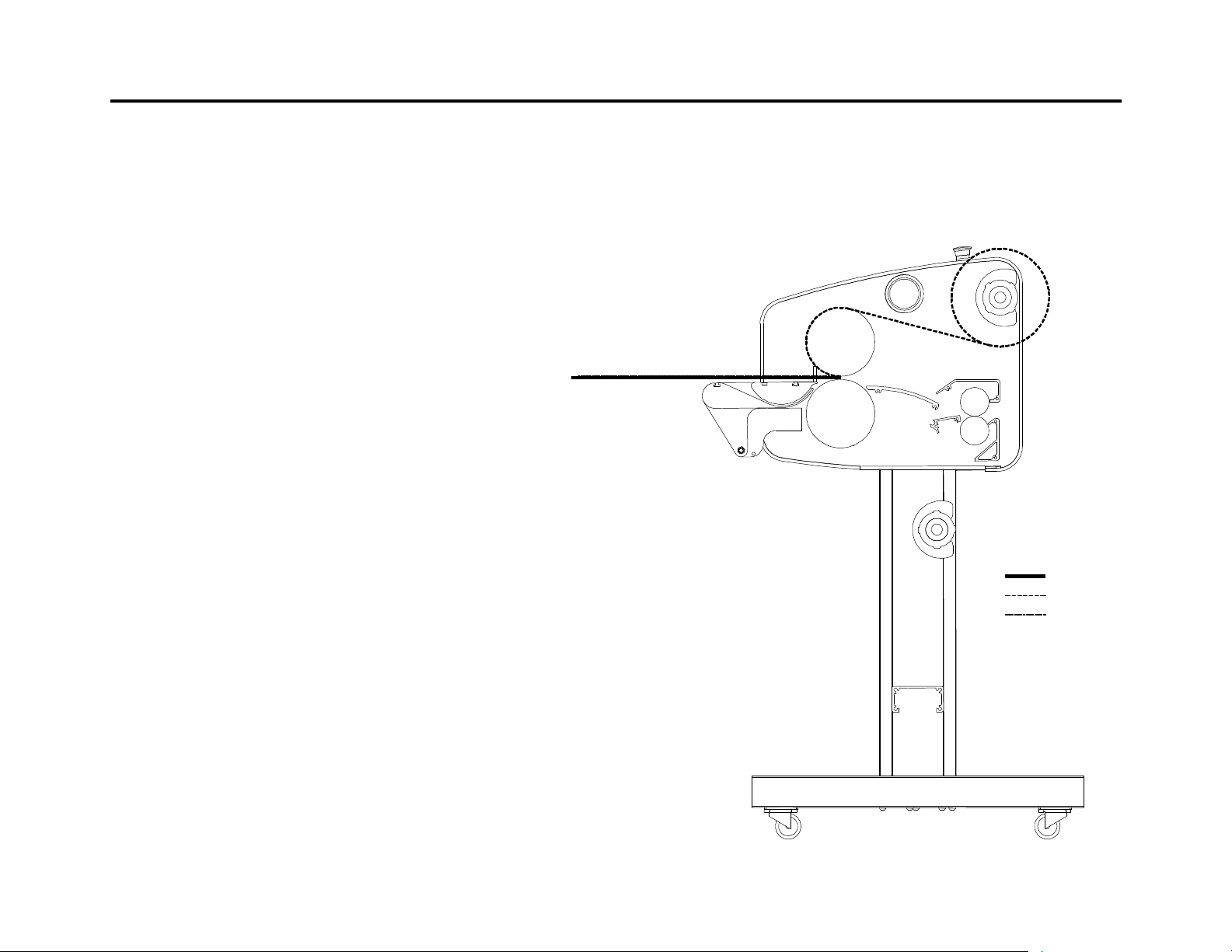
ONE STEP MOUNTING AND LAMINATING
Heat activated substrate
This process allows you to decal and mount in one step
by using a mounting board with heat activated adhesive
on one side
Preparation
n Set the top heaters roll temperature to 110ºC (230°F).
The bottom main roll off.
n Load the heat activated laminate on the top unwind
shaft.
Webbing
n Step one - Set the nip in correspondence with the
heat activated foam board you are using
n Step two - Lay the heat activated laminate across the
face of the top main roller.
n Step three - Use a piece of leader board to hold the
laminate under the top roller. When using this process
a leader board or your product must be in the nip.
This will prevent adhesive from coating the bottom
main roll.
n Step four – Run a sample piece of foam board without
an image. Check for adhesion, wrinkles, and
bubbles. Adjust your heat and brake tension
accordingly.
n Step five – A leader board should be in the nip. Place
an image on your mounting board, and press it
against the leader board. If you are mounting more
than one image, send them through consecutively.
Note: For thick laminates and images, run at a slower
speed. This will allow substrate adhesives to activate
properly.
Film Path
Media
- 18 - 3 H
Page 19
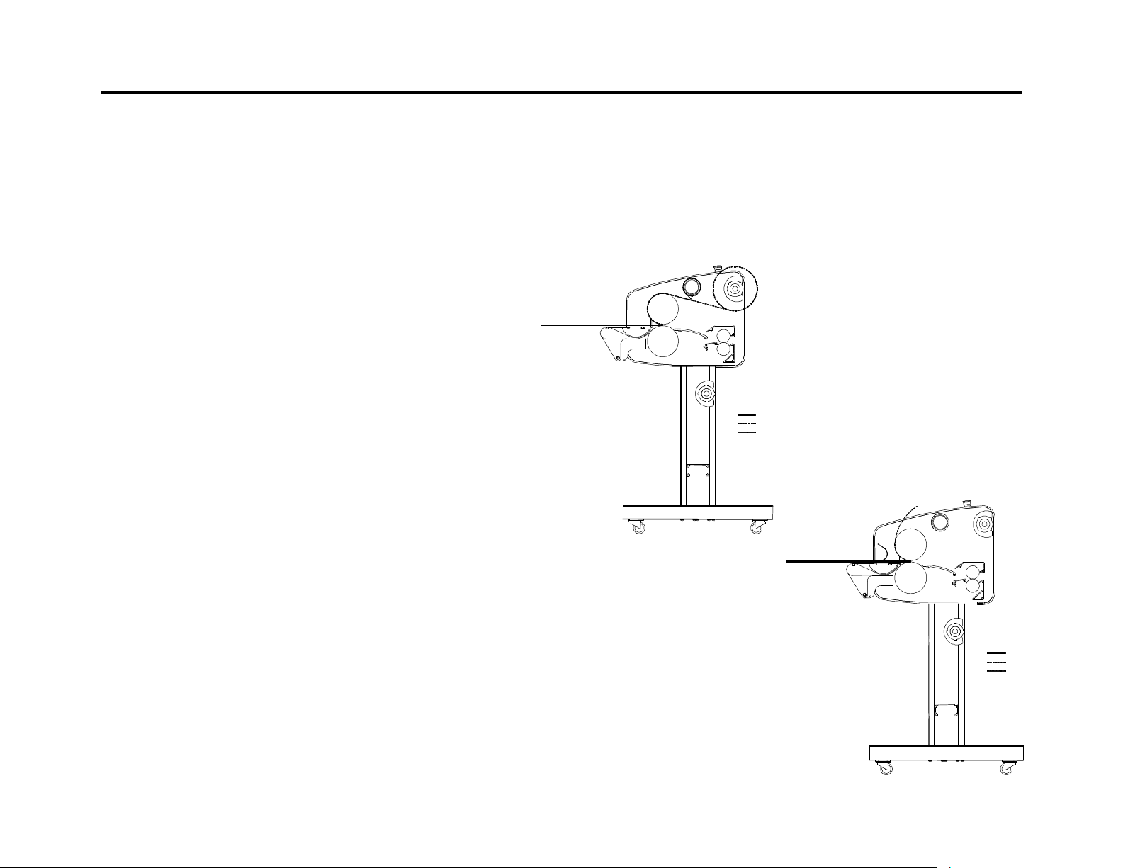
FACE MOUNTING
This process is used to cover a substrate with a clear
adhesive coating. Images can then be mounted face
down on a clear substrate.
Preparation:
Set the temperature of the top main roll to 130°F-140°F
(55 °C-60°C). The bottom main roll is off.
Load your adhesive on the top unwind.
laminating rollers. Stop the motor and raise the top
roller.
Step One
Prepare a leader board with the same thickness as the
board to be coated.
n Step one – Measure the thickness of the board being
Clear Substrate
Adhesive
Release Liner
coated and select the corresponding nip setting.
n Step two – Pull the adhesive from the top unwind and
lay it evenly over the top roller.
n Step three - Attach the top release liner to the top
Step Two
wind up station.
n Step four – Press the footswitch and push the
adhesive into the nip using the leader board. Release
the footswitch when the rear edge of the leader board
is in the roller nip.
n Step four - Position the board to be coated behind the
leader. When coating more than one board, ensure
that the boards follow each other without any gaps in
between them. You may use the footswitch or the
motor button.
n Step five - Follow the last board being coated with a
leader board. This allows the final board to clear the
- 19 - 3 H
Clear Substrate
Face Down Image
Release Liner
Page 20
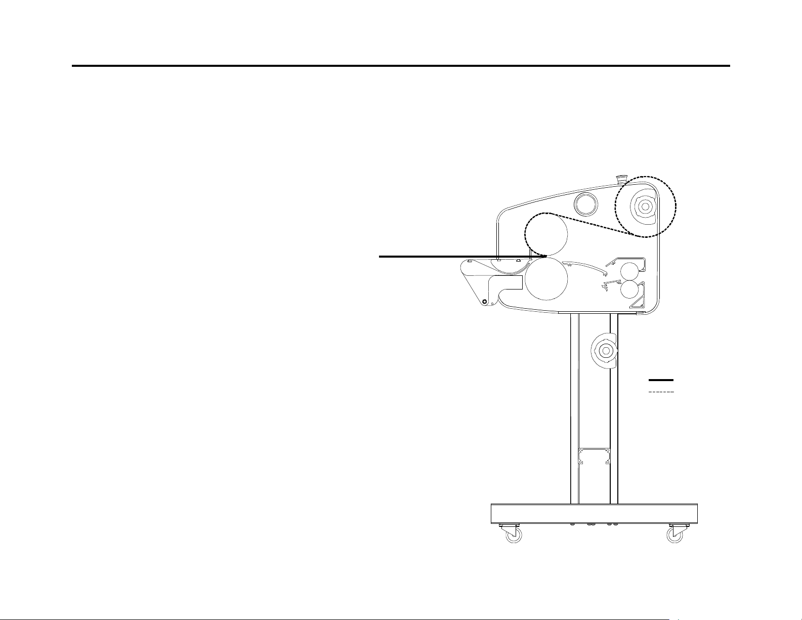
PRE-COATING A SUBSTRATE / CREATING A SLED
This process is used to cover substrates with a selfadhesive coating. Images can then be mounted on the
substrate. The same process is used to create a sled or
carrier board.
Preparation:
Set the temperature of the top main roll. Recommended
temperature is 120°F (49°C). The bottom main roll is off.
Mount your pressure sensitive adhesive on the top
unwind with the adhesive away from the roller.
Prepare a leader board with the same thickness as the
boards to be coated.
n Step one – Measure the thickness of the board to be
coated and select the corresponding nip setting.
n Step two - Pull the adhesive from the top unwind and
lay it evenly over the top roller.
n Step three - Press the footswitch and push the
adhesive into the nip using the leader board. Release
the footswitch when the rear edge of the leader board
is in the roller nip.
n Step four - Position the board to be coated behind the
leader. When coating more than one board, ensure
that the boards follow each other without any gaps in
between them. You may use the footswitch or the
motor button.
n Step five - Follow the last board being coated with a
leader board. This allows the final board to clear the
laminating rollers. Stop the motor and raise the top
roller.
Substrate
Adhesive
- 20 - 3 H
Page 21
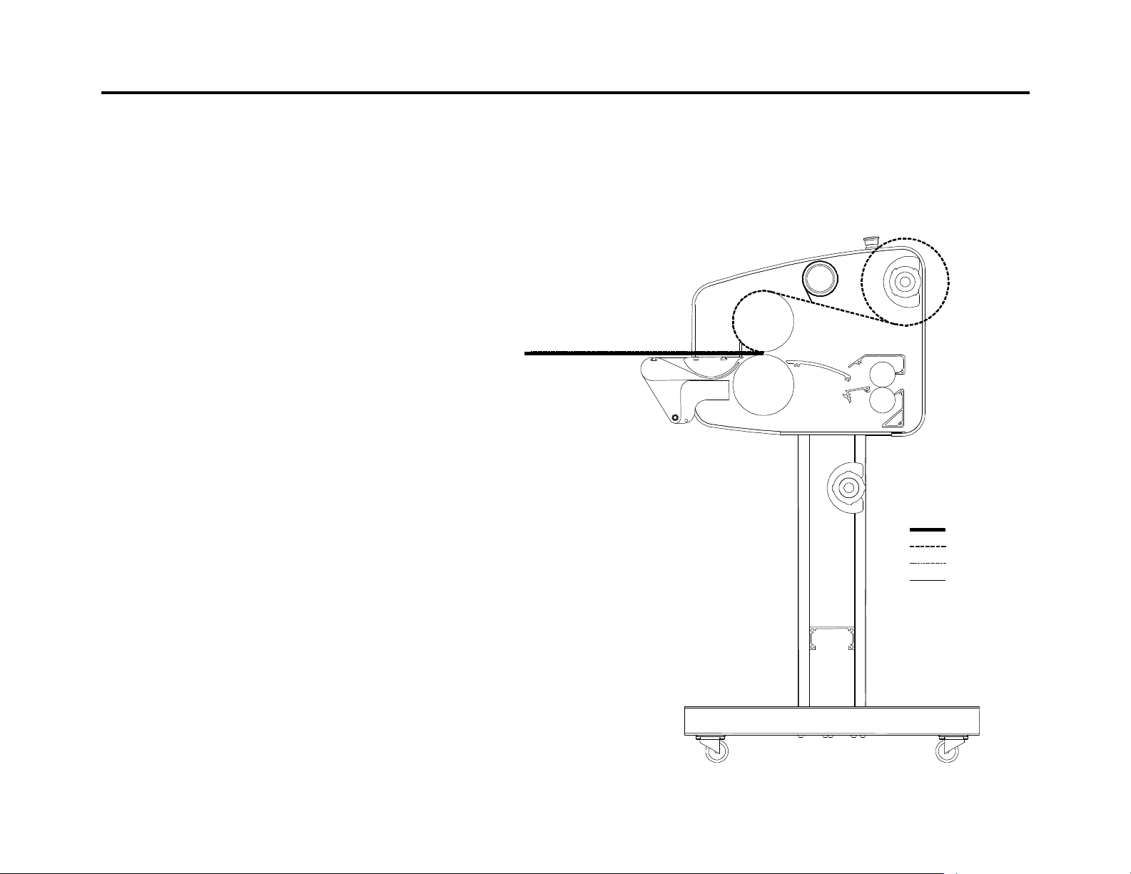
APPLYING OVERLAMINATE TO IMAGES USING
PRE-COATED SUBSTRATE
This process involves applying an over laminate to an
image with the use of a sled or pre-coated substrate.
Preparation:
Set your nip in accordance with the thickness of the
board you will be using.
Load a roll of pressure sensitive laminating film on the
top unwind shaft.
Do not remove the release liner from the sled.
Webbing
n Pull the film down from the top unwind. Separate the
film from the release liner and lay the film over the top
roller.
n Connect the release liner to the windup tube with a
piece of tape. Attaching the release liner to a
cardboard core (over the windup tube) will allow for
easier cleanup.
n Pull the film evenly across the face of the main rollers.
n Feed a leader board that is the same thickness as the
sled, into the nip. Make sure that the film is adhered
to the release liner on the leader board.
n When the sled comes through, place another leader
board between the nips to hold the film.
n You may now cut the image away from the sled.
Sled
Pressure Sensitive Film
Media
Release Liner
n Place an image face up on a sled and send it through
the nip.
- 21 - 3 H
Page 22

CLEANING AND MAINTENANCE
TROUBLESHOOTING
n Do not use an abrasive cleaner on any surface of
your laminator.
n Do not let water get onto the laminator. Water may
enter the electrical circuits and cause injury to
persons or damage to the laminator.
n Use an Image Roller cleaner to remove excess
adhesive. This is done while the rollers are hot.
When cleaning the top roller, place a piece of foam or
paper under it to keep waste adhesive from falling
onto the bottom roller.
n For a thorough cleaning, allow the rollers to cool and
then use isopropyl alcohol. Use a clean cloth.
* Warning! When using isopropyl alcohol, the rollers
must be cold. Isopropyl alcohol is flammable.
TECHNICAL ASSISTANCE
For Technical assistance, please contact your distributor.
When servicing, authorized technicians must disconnect
the power before removing side covers.
* Warning! Electrical shock hazard inside!
* Warning! The temperature readings will be affected
by high amplitude radio waves above 80MHz. If
fluctuation occurs, please contact your distributor or
technical service representative.
Problem – The machine will not turn on.
n Make sure that the emergency stop buttons were not
activated. Rotate to reset.
n Check the circuit breakers on the under side of the left
side plate.
n With the power disconnected, check the fuse in the
power supply. This should be done by authorized
safety or maintenance personnel.
Problem – The Motor will not turn.
n Check the motor circuit breaker. Refer to page 23 for
location.
n Make sure that the photo eyes are not blocked.
n With the power disconnected, check the fuse in the
motor control. This should be done by authorized
safety or maintenance personnel.
Problem – The machine is not heating up.
n Make sure the heaters are turned on. Check for the
LED to be illuminated on the control panel.
n Check the circuit breakers on the under side of the left
side plate.
- 22 - 3 H
Page 23
Problem – Images or prints are rippling as they are fed in.
n While feeding an image into the nip, place your hand
on the image to create tension.Problem – The film is
coming out rippled or boat waking.
n Make sure the machine is webbed properly.
n There may be improper film tension. Try to readjust
it.
n If you are using photo materials of heat sensitive
prints, run the laminator at a higher speed. Exposure
to heat at low speeds can cause waving.
Problem – The film is cloudy or mottled.
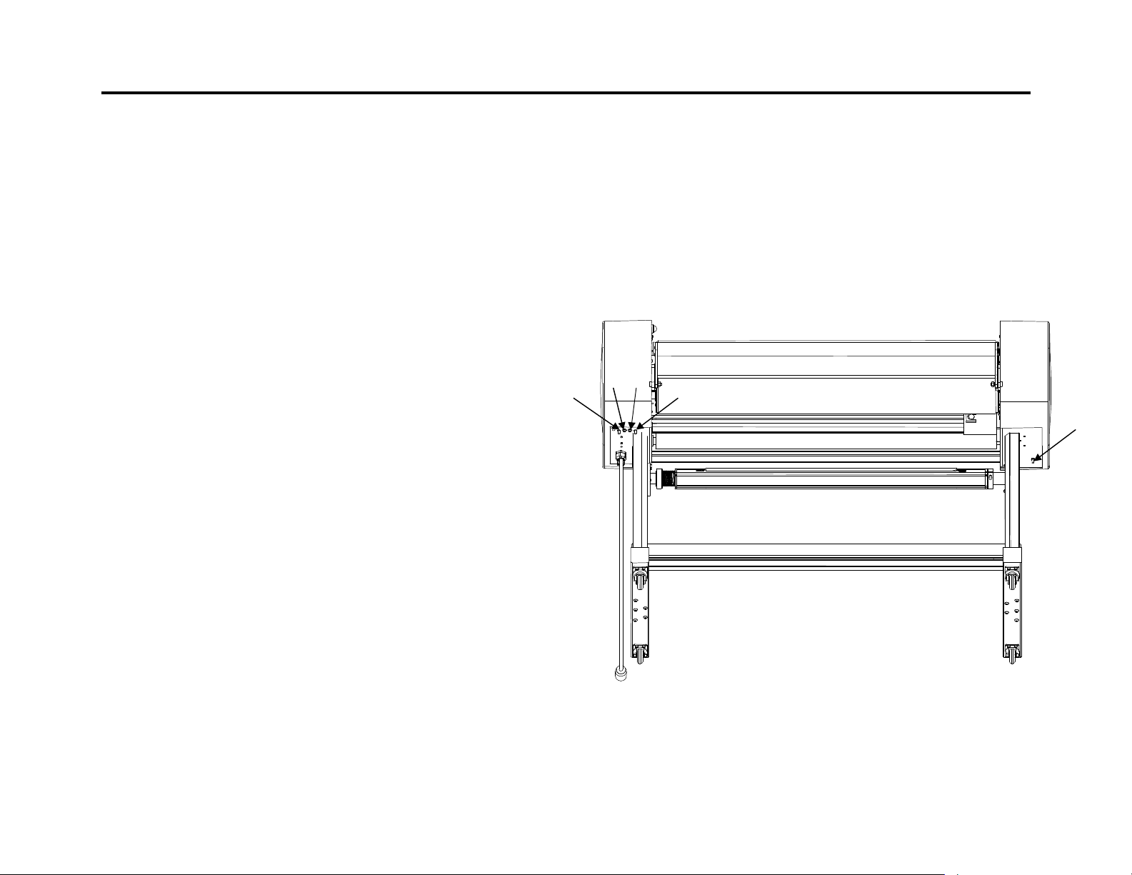
n 4. Bottom Heater (8 Amp) – Located under the control
side plate.
n 5. Common (16 Amp) for Domestic only – Located
under the control side plate.
Note: All breakers are visible and can be reset, from the
outside of the laminator.
4 3
5
2
n Increase the roller temperature or decrease the motor
speed.
Problem – Machine shuts down and display screen is
blinking.
n See page 24 Error codes for definition of problem.
LOCATION OF BREAKERS
n 1. Motor Breaker (0.8 Amp)– Located under the drive
side plate.
n 2. Control Power (2 Amp) – Located under the control
side plate.
n 3. Top Heater (8 Amp) – Located under the control
side plate.
- 23 - 3 H
1
Page 24

ERROR CODES
The machine shuts down and the display starts blinking.
This means that the software has detected an error in the
system. The numbers on the displays tell you what error
has occurred. The speed display will show the error
level. The top temperature display will show the error
data. These displays are used to find the problem. (The
bottom temperature display shows the current running
program number.) The first time an error occurs on your
machine, reset your power by depressing and resetting
the Emergency stop button. If the error occurs again, see
the chart. The chart defines some of the problems that
may have caused the error. If you cannot define the
problem, contact your distributor or sales representative
for technical assistance.
Note: After an error has shut down the system, the
power must be turned off for 10 seconds, using the
Emergency stop button. After 10 seconds, turn the power
on to restore the system.
* Warning! Authorized service technicians must
disconnect the power by using the power disconnect
before servicing.
Speed Display Top Temp Display Problem
Error Level 1.0 Error Data 1 The photo-eye has
failed.
Error Level 1.0 Error Data 5 The digital I/O (DIO)
card is defective.
Error Level 2.0 Error Data 0 Reset. If error
occurs again, the
digital I/O (DIO) card
is defective.
Error Level 2.1 Error Data 1 The Solid State
Relay for the top
main roll heater is
defective.
Error Level 2.1 Error Data 2 The Solid State
Relay for the bottom
main roll heater is
defective.
Error Level 2.1 Error Data 3 If the rollers are hot,
the Digital I/O (DIO)
card has failed. If
the rollers are cold,
The Analog Card has
failed.
Error Level 2.2 Error Data 1 The top
thermocouple is
defective or has a
bad connection.
Error Level 2.2 Error Data 2 The bottom
thermocouple is
defective or has a
bad connection.
Error Level 2.2 Error Data 3 The Analog I/O (AIO)
Card is defective.
Error Level 3.0 Error Data 0 The Nip Motor is
locked or the
encoder is defective.
- 24 - 3 H
Page 25
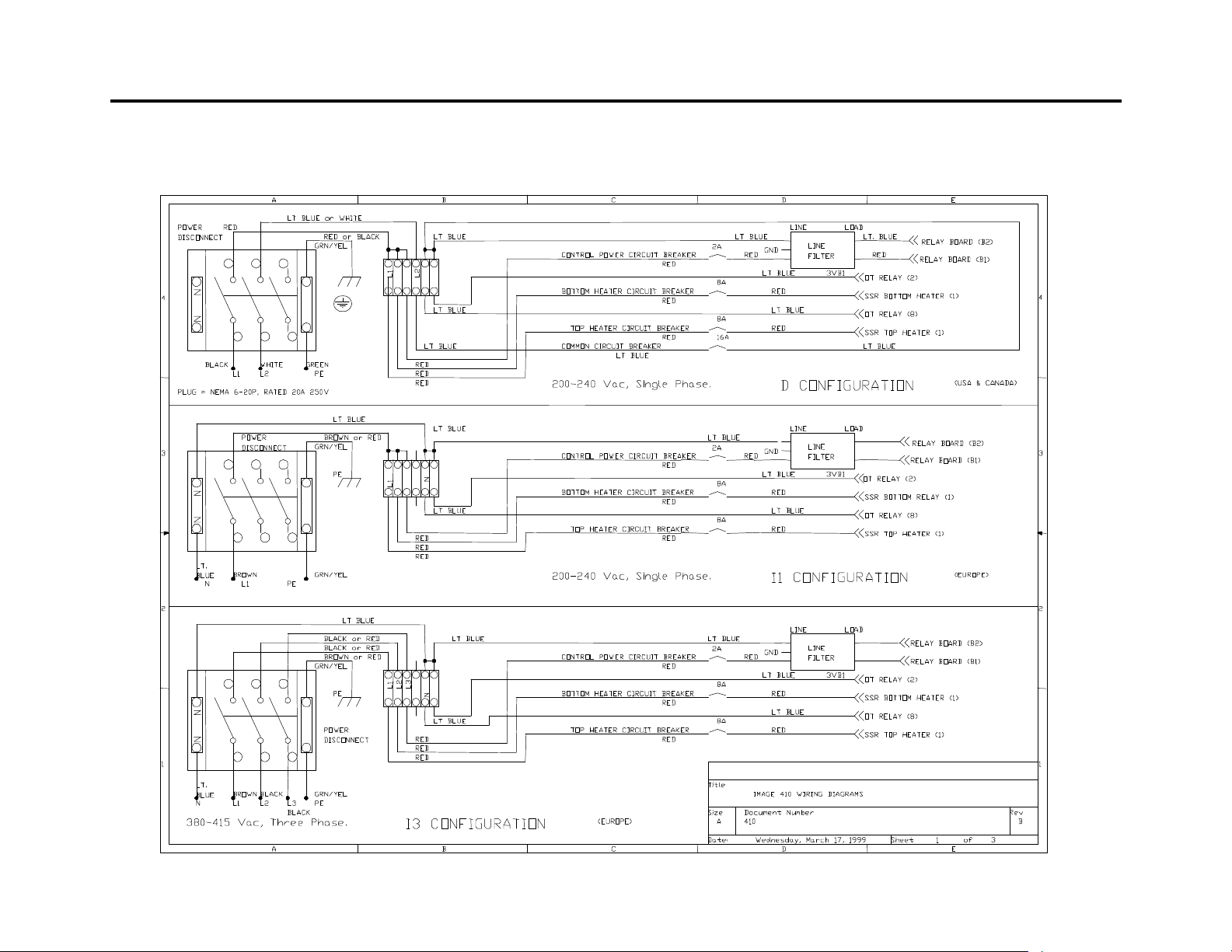
410 ELECTRICAL DIAGRAM
- 25 - 3 H
Page 26
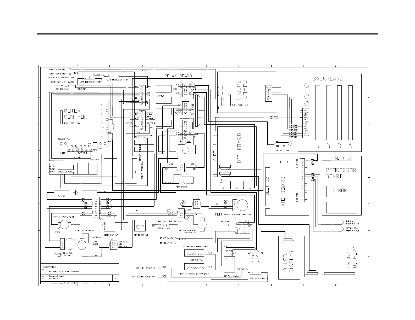
410 ELECTRICAL DIAGRAM
- 26 - 3 H
Page 27

REPLACEMENT PARTS
ACCESSORIES
Please contact your distributor or sales person for
replacement parts.
Description Part Number
Photo Eye 160104
DIO Card 131007
Solid State Relay 166060
AIO Card 131006
Thermocouple Kit 4011
Top Main Roll 691475
Bottom Main Roll 691474
Top Pull Roll 691472
Bottom Pull Roll 691473
Drive Motor 107400
Chill Shoe 729470
Motor Control 154620
The following accessories are supplied with the
laminator:
Accessory Part Number
User Manual 350051
Installation Acceptance
Terry Cloth Towel 350011
Image Roll Cleaner 350020
Zippy Cutter 350002
Edge Wrap Tool 350003
- 27 - 3 H
Page 28

GLOSSARY
Encapsulating – Sandwiching an image between two
heat activated films.
board coated with a self-wound pressure sensitive
adhesive. The silicone release liner is not removed
during coating and provides the necessary non-stick
surface.
Film – A synonym for laminate. The clear material used
in the laminating and encapsulating processes.
Mounting – Permanently affixing an image onto a backing
board.
Nip – The area where the top and bottom main rolls
meet.
Release Liner – The backing on a pressure sensitive,
heat activated laminate or mounting adhesive. Once the
release liner is peeled off, the adhesive layer becomes
exposed.
Decal – An image that has been laminates on top and
has an adhesive backing.
Leader Board – A piece of stiff card or foam board used
to lead film into the nip of the main rollers. In addition,
this is used when pre-coating to prevent adhesive getting
onto the rollers.
Pre-Coating – The process of coating a substrate with an
adhesive mounting film onto which an image can be
mounted.
Sled (Carrier Board) – A board that has a non-stick
surface that is used when laminating one side of an
image only. These are sometimes made using a flat
- 28 - 3 H
Page 29

For more information about Huntgraphics products,
contact your nearest sales office.
Hunt Graphics Americas
Railroad Ave Extension Building 8
P.O. Box 98
Beacon Falls, CT 06403-0098 USA
Phone: 203-729-5201 · 800-257-7325
Fax: 203-729-5639 · 800-966-4554
Hunt Graphics Americas
690 Gana Court
Mississauga, Ontario, L5S 1P2, Canada
Phone: +1-905-564-7717 · 0800-663-4868
Fax: 1-905-564-7079
Hunt Graphics Europe
Unit 6 Scimitar Park
Courtaulds Road
Basildon, Essex, England SS13 1ND
Phone: 00 44 1268 530331
Fax: 00 44 1268 727615
Hunt Graphics Pacific
Unit A, 13th Floor, Block 1
Leader Industrial Centre
Tsuen Wan, New Territories,
Hong Kong.
Phone: 00 852 2407 3738
Fax: 00 852 2408 0973
Hunt Graphics Europe
Kanaaldijk O.Z.3
P.O. Box 29, 8100 AA, Raalte.
The Netherlands
Phone: 00 31 572 345 500
Fax: 00 31 572 345 501
- 29 - 3 H
 Loading...