

Hunter Stoves Telford Inset 5 MKII Instructions For Installation/operation/maintenance/servicing
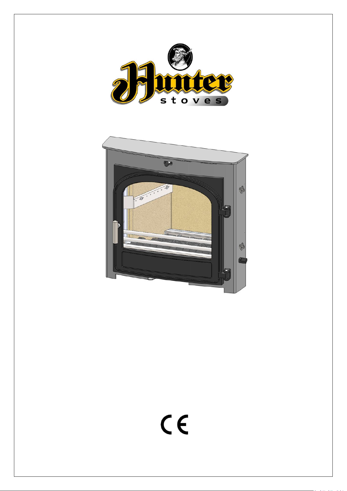
Telford Inset 5 MKII
Models: CVSTI05FM/CVTI05FM
Instructions for:
Installation/Operation/Maintenance/Servicing
JINTDI05 Rev E 20/04/15
CONTENTS INDEX:
TECHINCAL SPECIFICATION………………………………………………………………………………………………. 3
IMPORTANT INFORMATION…………………………………………………………………………………………….. 4
FLUE ADAPTOR INSTRUCTIONS............................................................................................ 6
DIRECT AIR ADAPTOR INSTRUCTIONS.................................................................................. 7
PRE INSTALLATION REQUIRMENTS…………………………………………………………………………………… 9
REMOVING INTERNAL COMPONENTS.................................................................................. 12
INSTALLATION INSTRUCTIONS………………………………………………………………………………………….. 14
COMMISSIONING AND HANDOVER………………………………………………………………………………….. 15
USER INSTRUCTIONS………………………………………………………………………………………………………… 16
MAINTENANCE & SERVICING…………………………………..……………………………………………………….. 19
SPARES INFORMATION…………………………………………………………………………………………………….. 21
COMMISSIONING & INSTALLATION CHECK LIST……………..……………….……………………………….. 24
SERVICE RECORDS…………………………………………………………………………………………………………….. 25
Hunter Stoves,
Emperor Way,
Exeter Business Park,
Exeter,
Devon. EX1 3QS
Email - info@hunterstoves.co.uk
Website - www.hunterstoves.co.uk
WARRANTY
Hunter Stoves appliances come with a standard 2 year warranty, however this excludes naturally wearing
“consumable” components and the use of un-authorised fuels.
Consumables are deemed to be;
Glass, Seals, Gaskets, Grate Components, Log Retainers, Baffles and the surface finish of the appliance.
The Warranty will only be valid if the appliance is installed by an appropriately qualified engineer in
accordance with the manufacturer’s instructions and to the appropriate Building Regulations and/or Local ByLaws and serviced within 12 months of installation.
Hunter Stoves will also support an extended 5 year warranty on external Cast Iron components such as Doors,
Flue Collars and Covers.
If this appliance is purchased through an un-authorised stockist or an internet trader Hunter Stoves are only
obliged to support the statutory requirements.
This appliance must be regularly serviced and maintained, using only Hunter Stoves approved components for
the Warranty to be valid.
JINTDI05 Rev E 20/04/54
2
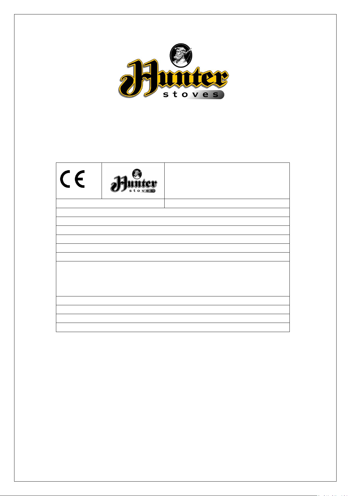
TELFORD INSET 5 MKII
Hunter Stoves, Emperor Way,
Exeter Business Park, Exeter,
Devon. EX1 3QS
BS/EN 13229
UKAS# 0692
Stove Mass: 100 kg
NOMINAL OUTPUT: 4.9 KW
CO Emission at 13% O2: 0.19%
Mean Flue Gas Temperature: 292°C
EFFICIENCY: 77.1%
Flue Gas Mass Flow: 4.3 g/s
Minimum clearance to combustible material
Top of Fire Surround:
200mm
Side of Fire Surround:
150mm
Side Wall:
300mm
This appliance is suitable for intermittent burning
This appliance is not suitable for use in a shared flue
Read and follow the operating instructions
Use only recommended fuels
15
Telford Inset 5 MKII
TECHNICAL SPECIFICATION
JINTDI05 Rev E 20/04/54
3
IMPORTANT INFORMATION
PLEASE READ THESE INSTRUCTIONS PRIOR TO INSTALLATION AND OPERATION.
KEEP THESE INSTRUCTIONS IN A SAFE PLACE FOR FUTURE REFERANCE AND SERVICING.
THIS APPLIANCE WILL BECOME HOT WHEN USED IN ACCORDANCE WITH THESE INSTRUCTIONS,
HUNTER STOVES RECOMMEND THAT AN APPROVED GUARD IS USED TO PROTECT THE YOUNG,
ELDERLY OR INFIRM FROM HARM.
THE INSTALLER COMMISSIONING SHEET CAN BE FOUND ON THE BACK COVER.
PLEASE ENSURE THAT IT IS COMPLETED PRIOR TO USE.
GENERAL GUIDANCE
It is important that your stove is correctly
installed and operated as Hunter Stoves cannot
accept responsibility for any fault arising through
incorrect installation, use, maintenance or
servicing.
These instructions cover the basic principles to
ensure satisfactory installation of the stove,
although detail may need slight modification to
suit particular local site conditions.
The installation must comply with current Building
Regulations, National and European Standards,
Local Authority Byelaws and other specifications
or regulations as they affect the installation of the
appliance.
The Building Regulations requirements may also
be met by adopting the relevant
recommendations in the current issues of British
Standards BS 8303 and BS EN 15287-1.
Only use approved fuels on this appliance.
Information about this can be found on Page 18.
This is a Domestic Appliance and must only be
used in accordance with these instructions.
Do not place articles that are affected by high
temperatures on, or near, this appliance. Do not
place furniture or other items within 900mm of
the front of this appliance. See the note on
material clearances on page 11.
Extractor Fans and/or Cooker Hoods must not be
installed in the same space or room as this can
cause the appliance to emit fumes into the room.
Do not obstruct the ventilation required for the
safe use of this appliance.
COMPETENT PERSONS SCHEME
Hunter Stoves recommend that this stove is
installed by a member of an accredited
competent persons scheme e.g. HETAS.
If the installer is not a member of a competent
person’s scheme, it is a legal requirement, in the
UK, to notify your Local Building Control Officer in
advance of any installation work starting.
HEALTH AND SAFETY PRECAUTIONS
Special care must be taken when installing the
stove such that the requirements of the Health
and Safety at Work Act are met.
HANDLING
This appliance is very heavy. Adequate facilities
must be available for loading, unloading and site
handling.
FIRE CEMENT
Some types of fire cement are caustic and should
not be allowed to come into contact with the skin.
In case of contact, wash immediately with plenty
of water.
JINTDI05 Rev E 20/04/54
4
ASBESTOS
This Stove contains no asbestos. If there is a
possibility of disturbing any asbestos in the course
of installation then please seek specialist guidance
and use appropriate protective equipment.
METAL PARTS
When installing or servicing this stove, care should
be taken to avoid the possibility of personal injury.
MODIFICATION
No unauthorized modification of this appliance
should be carried out.
SAFETY
WARNING!
This appliance will be hot when in operation and
due care should be taken. The supplied gloves
may be used to open the door and operate the air
controls.
AEROSOLS
Do not use an aerosol spray on or near the stove
when it is alight.
FIREGUARDS
Always use a fireguard in the presence of children,
the elderly or the infirm. The fireguard should be
manufactured in accordance with BS8423 –
Fireguards for use with solid fuel appliances.
DO NOT OVER-FIRE
It is possible to fire the stove beyond its design
capacity. This could damage the stove so watch
for signs of over-firing. If any part of the stove
starts to glow red, the stove is in an over-fire
situation and the controls should be adjusted
accordingly. Never leave the stove unattended for
long periods without first adjusting the controls to
a safe setting. Careful air supply control should be
exercised at all times.
FUME EMISSION
Properly installed and operated, this appliance
will not emit fumes. Occasional fumes from deashing and refueling may occur. Persistent fume
emission must not be tolerated.
This appliance should not be operated with the
door open.
If fume emission does persist then the following
action should be taken immediately;
Open Doors and windows to ventilate room.
Let the fire out, or eject and safely dispose of
fuel from the appliance.
Check for flue/chimney blockage and clean if
required.
Do not attempt to relight the fire until the
cause has been identified and corrected.
If necessary seek professional advice.
ADVERSE WEATHER
In a small number of installations, occasional local
weather conditions (e.g. wind from a particular
direction) may cause downdraught in the flue and
the stove to emit fumes. In these circumstances
the stove should not be used. A professional flue
installer will be able to give advice on solutions to
this problem (e.g. anti-downdraught cowl).
CARBON MONOXIDE DETECTOR
Hunter Stoves recommend a Carbon Monoxide
Detector that conforms to the latest issue of BS
EN 50292 is placed in the same room as the
appliance. The installation of such an alarm is not
considered as a substitute for regular
maintenance or servicing or the appliance and
Flue system.
IN THE EVENT OF A CHIMNEY FIRE:
Raise the alarm
Call the Fire Brigade
Close appliance air controls
Move furniture, ornaments etc. away
Place a fireguard in front of stove
Check the chimney breast for signs of excessive
heat.
If the wall is becoming excessively hot, move
furniture away.
Ensure the Fire Brigade can gain access to your
roof space in order to check for fire spread.
JINTDI05 Rev E 20/04/54
5
INSTRUCTIONS FOR FITTING THE
Self Tapping Screw Holes.
OPTIONAL FLUE ADAPTOR
This product is designed to fit into a standard 16
inch fireback.
An optional Flue Adaptor (Part No: HCN05074) for
Ø125mm flexible liners is supplied with this
Appliance.
N.B.The flue adaptor is designed to allow
connection of a 125mm flexible flue liner or
125mm single skin flue pipe to the flue outlet
of the Inset 5 MKII room heater. Some
modification of the fireplace opening will be
necessary to allow sufficient room to
accommodate the adaptor. The adaptor has a
125mm (5”) flue socket designed to accept
flue liner adaptors and flue pipe. Flexible flue
liners should not be directly connected to the
Inset 5 MKII Flue adaptor as this may result in
deformation of the liner.
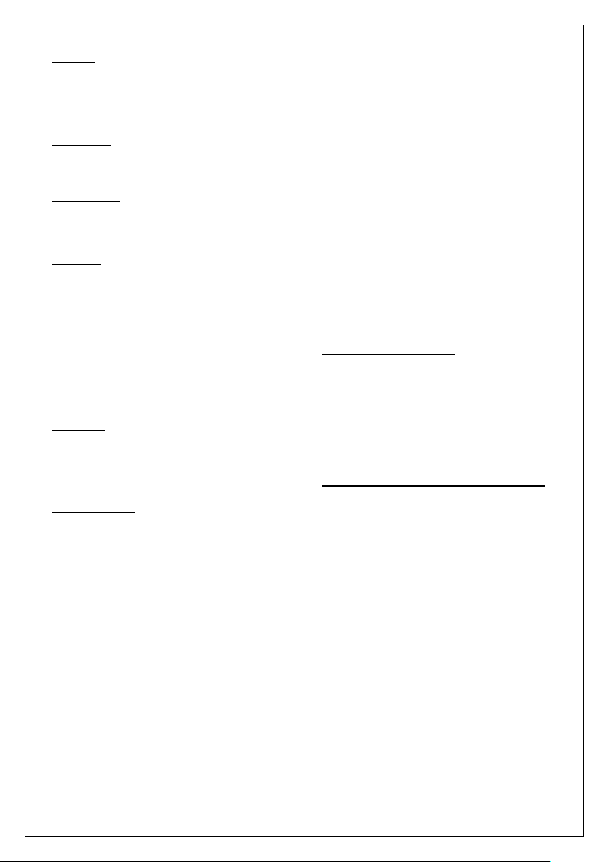
TO FIT THE FLUE ADAPTOR
Remove all the stove interior parts and door(s) as
detailed on (page 12).
Unscrew the two M8 screws from the inside of the
stove and remove the Flue Infill plate.
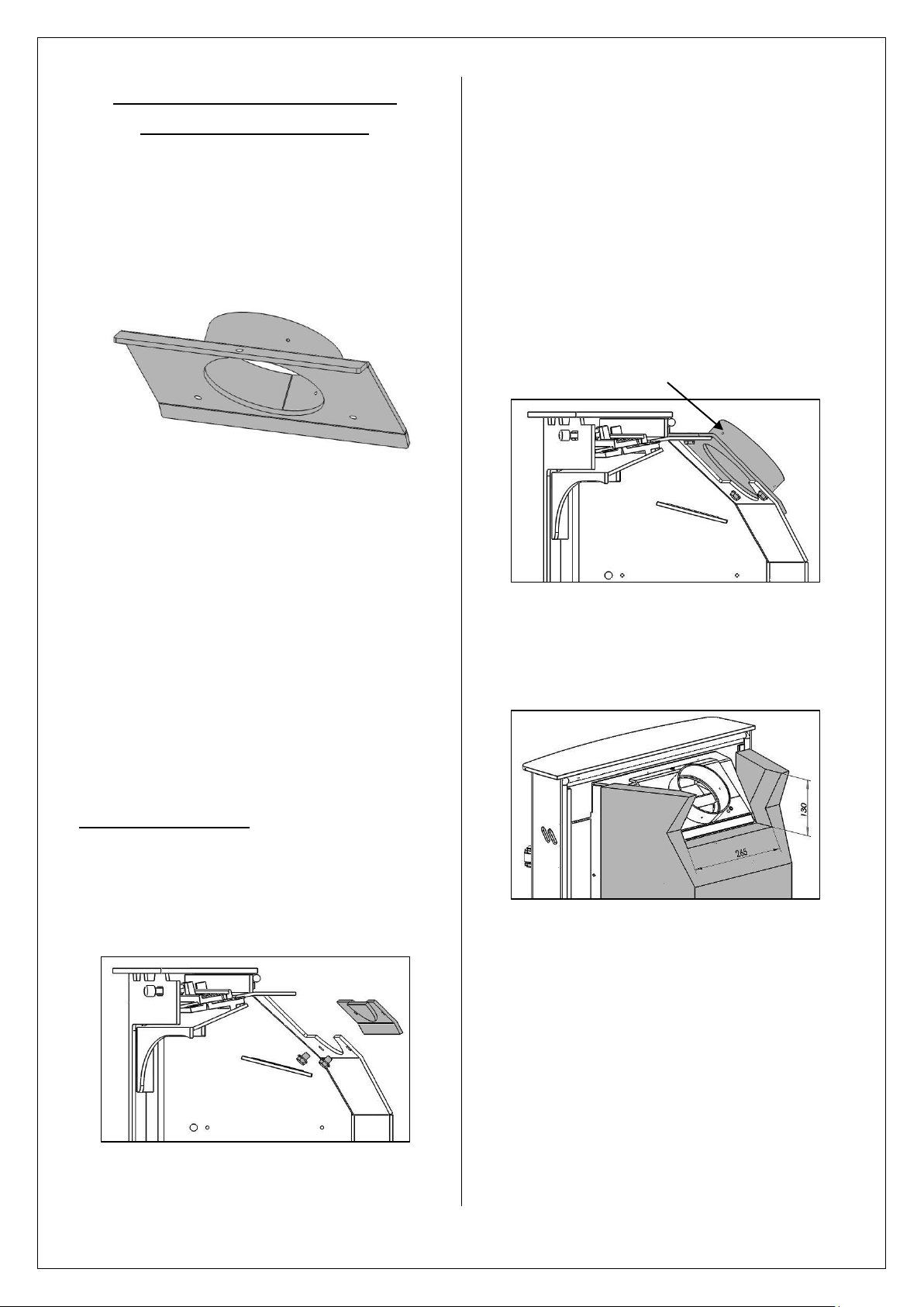
Replace the Flue Infill Plate with the Flue Adaptor.
Apply fire cement to the mating surfaces of the
adaptor and stove flue outlet.
Screw the Flue adaptor in place with the three M8
screws and washers from the inside of the stove.
If connecting to a flexible flue liner, use a flexible
flue liner to single skin flue adaptor to connect to
the Inset 5 MKII adaptor. Use self tapping screws
through the holes provided to fix the flue in place.
The upper section of the fireback will need to be
removed to fit the stove with the optional flue
adaptor fitted.
JINTDI05 Rev E 20/04/54
6
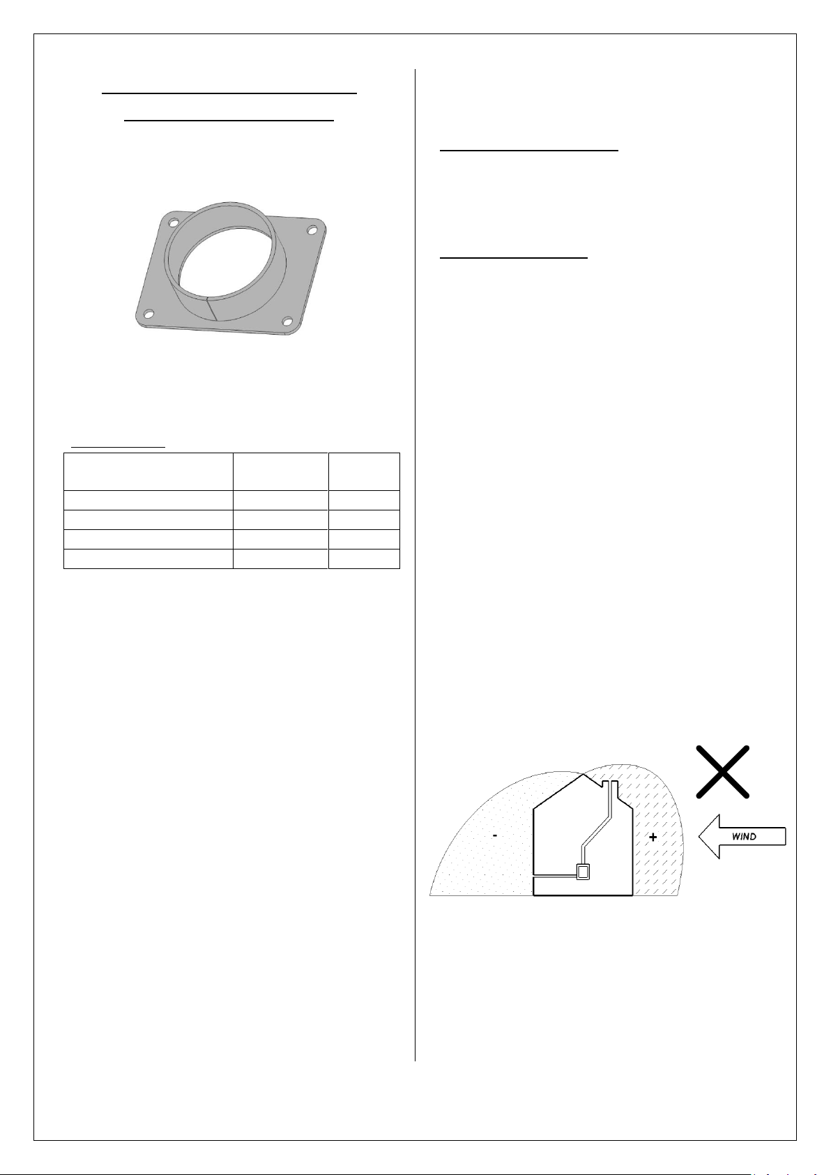
INSTRUCTIONS FOR FITTING THE
Description
Part
Number
Quantity
Adaptor Coupling
DACM80
1
Aluminium Duct
DAPM80
1
Bull Nose Vent & Flange
DAVM80 1 Duct Clip
FHC1060135
1
OPTIONAL DIRECT AIR KIT
An optional Direct Air Adaptor (Part No: HCN05079)
is supplied with this appliance.
If the Direct Air Adaptor is to be fitted a Direct Air
kit will need to be purchased.
Direct Air Kit Code: (HCE16ARRT007)
Contents of kit
These instructions cover the installation of the
Direct Air Adaptor kit to the Hunter Inset 5 MKII
stoves.
This Direct Air Adaptor allows the combustion air
for the stove to be ducted directly from outside.
N.B. This does not constitute a “room sealed
installation” as some air is allowed to pass
through the stoves inlet duct. This provides relief
from draught fluctuations and will help to clear the
air in the room should flue gas spillage occur.
It is important that your stove is correctly installed
as Hunter cannot accept responsibility for any fault
arising from incorrect use or installation.
The installation must comply with current Building
Regulations, national and European standards,
Local Authority Byelaws and other specifications or
regulations as they affect the installation of the
stove.
The Building Regulations requirements may also
be met by adopting the relevant recommendations
in the current issues of British Standards BS 8303
and BS EN 15287-1.
Competent Persons Scheme
Hunter recommend that this Direct Air Adaptor is
installed by a member of an accredited competent
persons scheme e.g. Hetas.
Siting of the Inlet Grille
Due consideration should be given to the siting of
the inlet grill to ensure that strong winds on either
the flue terminal, inlet grill or the building itself
will not cause the flow of flue gasses or
combustion air to be stalled or reversed.
If in doubt the inlet duct should be divided by a tee
piece and two inlet grills fitted on opposite sides of
the building. Alternatively the duct may be
connected to a space or chamber under the floor
on which the stove is installed which is ventilated
from all sides of the building.
Take note of prevailing winds in the area as well as
any tall buildings or trees that may be present and
could potentially create pressure zones around the
chimney terminal.
Do not fit the inlet vent on the downwind side of
the building unless the flue terminal is also on the
same side. Otherwise downdraft may occur in
windy conditions.
Care must also be taken when siting the inlet grille
to ensure that it will not become susceptible to
blockage.
JINTDI05 Rev E 20/04/54
7
Clearances to Combustible materials
In extreme circumstances it may be possible for
the flow of flue gasses in the stove to become
reversed. In this condition the duct will become
heated by the hot flue gas and consideration must
therefore be given to preventing the risk of fire.
The duct must be insulated wherever there is any
combustible material within a distance of 300mm
from the surface of the duct. It is also advisable to
insulate the duct wherever possible to reduce the
risk of condensation.
Where necessary the duct should be insulated
with 30mm thick Rockwool Rocklap H&V Pipe
Sections, having a nominal density not less than
120kg/m³, with a factory applied facing of
reinforced aluminium foil incorporating integral
lap for fixing. Fixing to be in accordance with
manufacturer’s instructions.
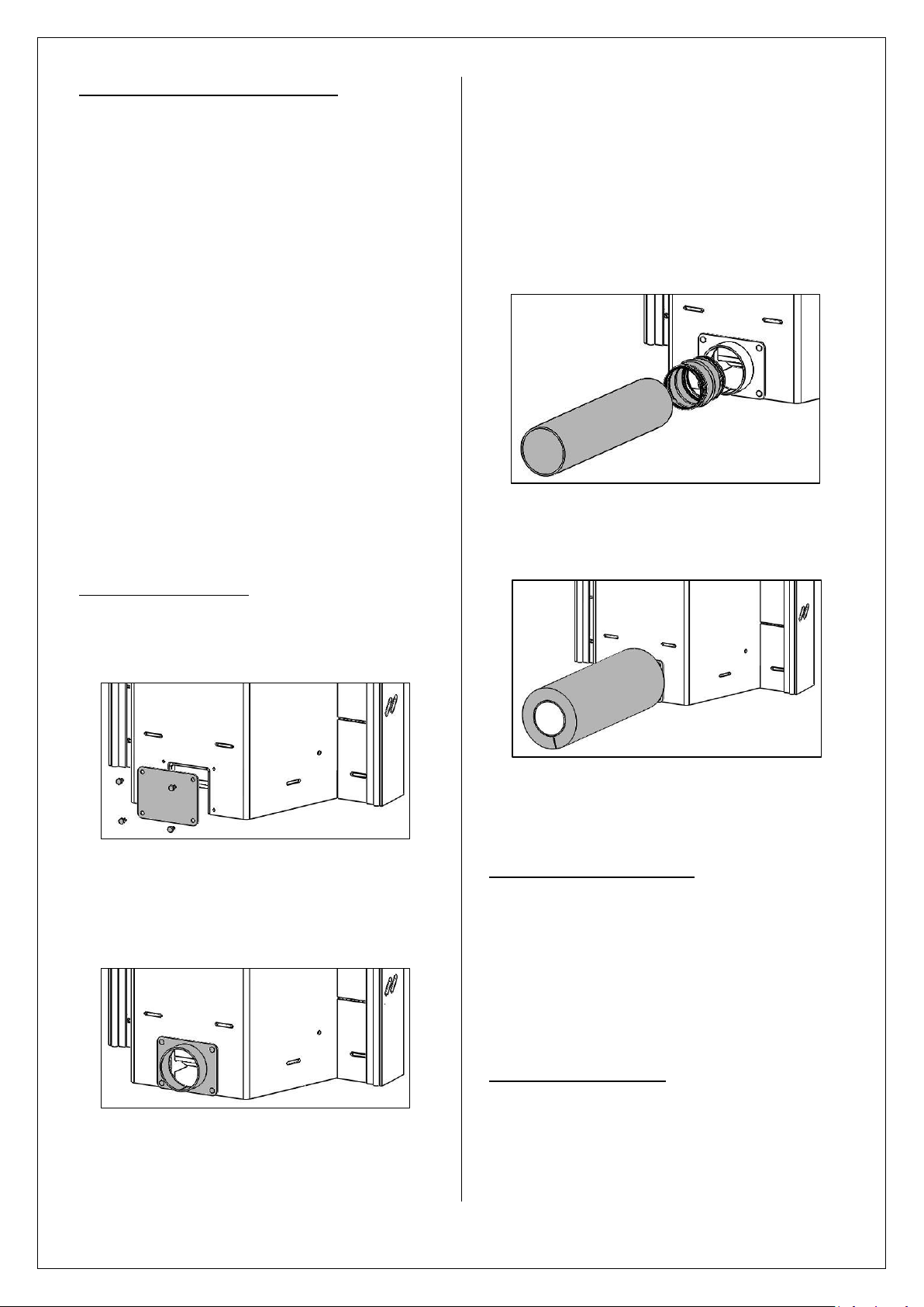
Connection to the stove
Fit the Direct Air Adaptor to the rear of the stove.
Unscrew the four M6 screws and remove the
Direct Air cover plate.
ducting and any insulation is suitably sized and
positioned. Carry out any necessary remedial
work.
Measure and cut the duct as necessary, allowing
an extra 50mm to make the connection to the inlet
grille. Connect the duct to the adaptor using the
Direct Air Coupling.
Where necessary fit the insulation to the duct,
sealing all joints with foil tape.
Replace the Direct Air Cover Plate with the Direct
Air adaptor.
Screw the Direct Air adaptor in place with the four
M6 screws and washers.
Measure the fireplace opening and check that
there is sufficient room for the Direct Air Adaptor
and that the position of any hole for the flexible
Pass the duct through the prepared hole and
manoeuvre the stove into position.
Connection to the Inlet Grille
Offer the Inlet grille into position on the outside
wall and where necessary mark and drill the fixing
holes.
Connect the Inlet grille to the duct using the clamp
provided. Apply a bead of sealant to the back face
of the inlet grille and fix the grille to the wall.
Commissioning
Carry out the commissioning procedure as
described in these instructions.
JINTDI05 Rev E 20/04/54
8
 Loading...