

Hunter Stoves Telford Inset 20DB CVWSTI08DBFM, Telford Inset 20DB, Telford Inset 20DB CVWTI08DBFM Instructions For Installation/operating/maintenance/servicing
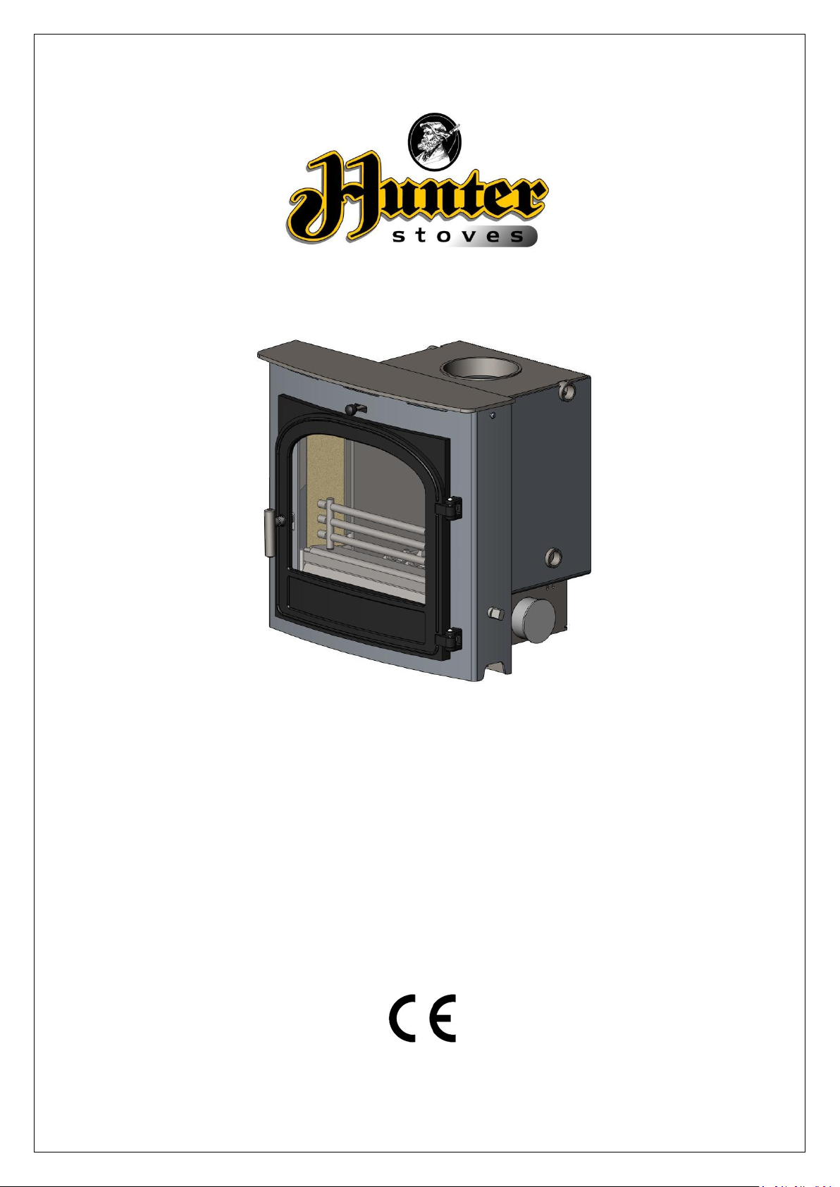
Telford Inset 20DB
Multifuel Boiler Stove
Model: CVWSTI08DBFM/CVWTI08DBFM
Instructions for:
Installation/Operating/Maintenance/Servicing
JINTDBW09 Rev B 05/03/15
CONTENTS INDEX:
TECHNICAL SPECIFICATION……………………………………………………………………………………………… 3
IMPORTANT INFORMATION……………………………………………………………………………………………. 4
REMOVING INTERNAL COMPONENTS……………………………………………………………………………… 6
APPLIANCE DIMENSIONS ……………………………………………………………………………………………… 7
PRE INSTALLATION REQUIREMENTS…………………………………………………………………………………. 8
INSTALLATION INSTRUCTIONS………………………………………………………………………………………… 11
INSTALLATION OF HEATING & HOT WATER……………………………………………………………………………. 13
COMMISSIONING AND HANDOVER………………………………………………………………………………….. 15
OPERATING INSTRUCTIONS……………………………………………………………………………………………… 16
MAINTENANCE & SERVICING…………………………………..……………………………………………………….. 19
SPARES INFORMATION……………………………………………………………………………………………………… 21
COMMISSIONING & INSTALLATION CHECK LIST……………..……………….……………………………….. 24
SERVICE RECORDS…………………………………………………………………………………………………………….. 25
Hunter Stoves,
Emperor Way,
Exeter Business Park,
Exeter,
Devon. EX1 3QS
Email info@hunterstoves.co.uuk
Website http://www.hunterstoves.co.uk
WARRANTY
Hunter Stoves appliances come with a standard 2 year warranty; however this excludes naturally
wearing “consumable” components and the use of un-authorised fuels.
Consumables are deemed to be; Glass, Seals, Gaskets, Grate Components, Log Retainers, Baffles,
Thermostat and the surface finish of the appliance.
The Warranty will only be valid if the appliance is installed by an appropriately qualified engineer in
accordance with the manufacturer’s instructions and to the appropriate Building Regulations and/or
Local By-Laws and serviced within 12 months of installation.
Hunter Stoves will also support an extended 5 year warranty on external Cast Iron components such
as Doors, Flue Collars and Covers.
If this appliance is purchased through an un-authorised stockist or an internet trader Hunter Stoves
are only obliged to support the statutory requirements.
This appliance must be regularly serviced and maintained, using only Hunter Stoves approved
components for the Warranty to be valid
JINTDBW09 Rev B 05/03/15
2
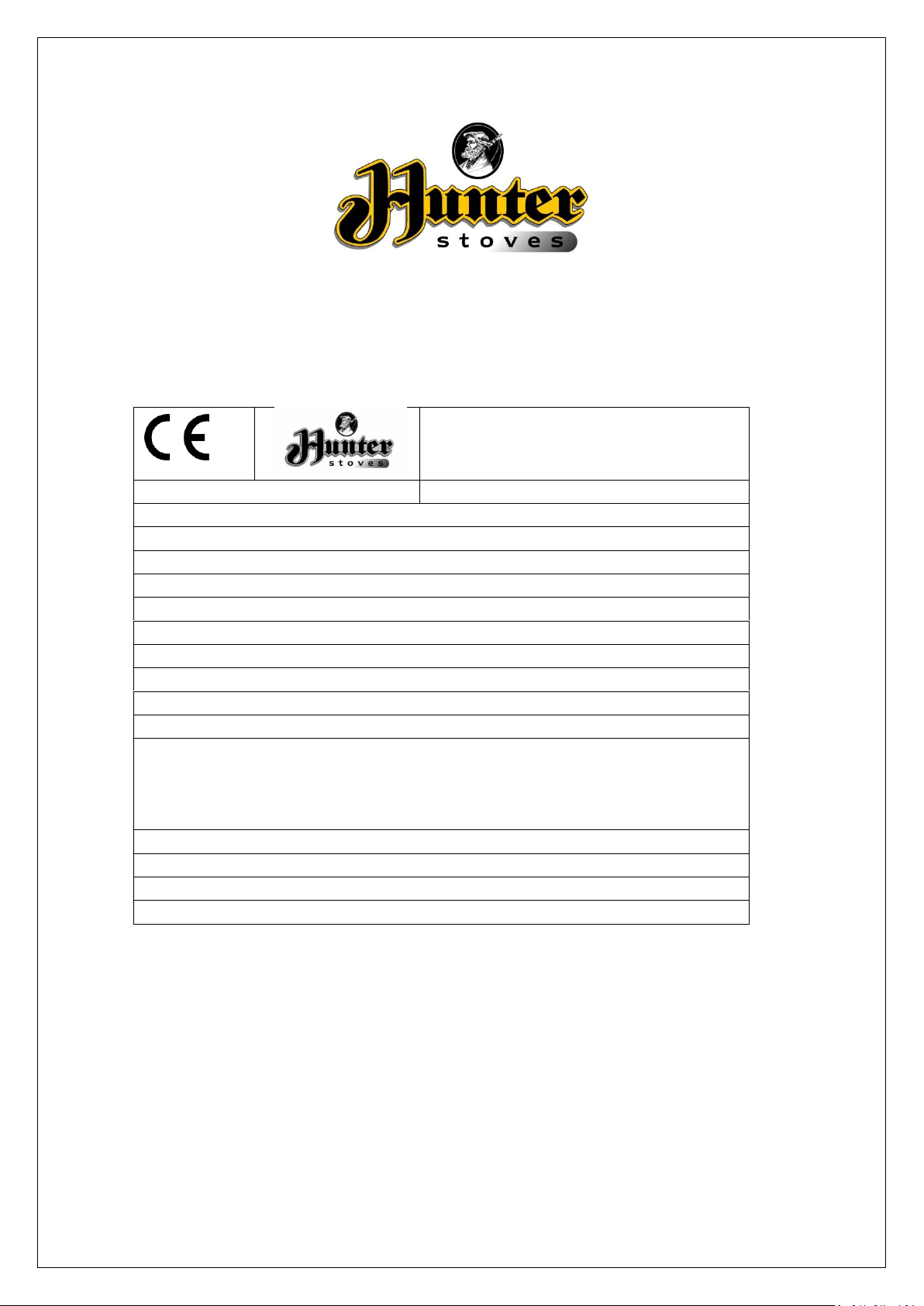
INSET TELFORD 20DB
Unit 8 Emperor Way, Exeter Business
Park, Exeter, Devon, EX1 3QS
BS/EN 13229
UKAS# 0692
Stove Mass: 127.67kg
NOMINAL OUTPUT: 15.8KW
NOMINAL OUTPUT TO WATER: 10.7KW
NOMINAL OUTPUT TO SPACE: 5.1KW
CO Emission at 13% O2: 0.33%
Mean Flue Gas Temperature: 385°C
EFFICIENCY: 69.9%
Flue Gas Mass Flow: 14.1g/s
Maximum operating water temperature in °C: 100°C
Maximum operating pressure in bar: 1.2 Bar
Minimum clearance to combustible material
Top of Fire Surround:
150mm
Side of Fire Surround:
75mm
Side Wall:
200mm
This appliance is suitable for intermittent burning
This appliance is not suitable for use in a shared flue
Read and follow the operating instructions
Use only recommended fuels
15
Inset Telford 20DB
Technical Specification
JINTDBW09 Rev B 05/03/15
3
IMPORTANT INFORMATION
PLEASE READ THESE INSTRUCTIONS PRIOR TO INSTALLATION AND OPERATION.
KEEP THESE INSTRUCTIONS IN A SAFE PLACE FOR FUTURE REFERENCE AND SERVICING.
THIS APPLIANCE WILL BECOME HOT WHEN USED IN ACCORDANCE WITH THESE INSTRUCTIONS.
HUNTER STOVES RECOMMEND THAT AN APPROVED GUARD IS USED TO PROTECT THE YOUNG,
ELDERLY OR INFIRM FROM HARM.
THE INSTALLER COMMISSIONING SHEET CAN BE FOUND ON THE BACK COVER.
PLEASE ENSURE THAT IT IS COMPLETED PRIOR TO USE.
GENERAL GUIDANCE
It is important that your stove is correctly
installed and operated as Hunter Stoves cannot
accept responsibility for any fault arising through
incorrect installation, use, maintenance or
servicing.
These instructions cover the basic principles to
ensure satisfactory installation of the stove,
although detail may need slight modification to
suit particular local site conditions.
The installation must comply with current Building
Regulations, National and European Standards,
Local Authority Byelaws and other specifications
or regulations as they affect the installation of the
appliance.
The Building Regulations requirements may also
be met by adopting the relevant
recommendations in the current issues of British
Standards BS 8303 and BS EN 15287-1.
Only use approved fuels on this appliance.
Information about this can be found on Page 18.
This is a Domestic Appliance and must only be
used in accordance with these instructions.
Do not place articles that are affected by high
temperatures on, or near, this appliance. Do not
place furniture or other items within 700mm of
the front of this appliance. See the note on
material clearances on page 10.
JINTDBW09 Rev B 05/03/15
Extractor Fans and/or Cooker Hoods must not be
installed in the same space or room as this can
cause the appliance to emit fumes into the room.
Do not obstruct the ventilation required for the
safe use of this appliance.
COMPETENT PERSONS SCHEME
Hunter Stoves recommend that this stove is
installed by a member of an accredited
competent persons scheme e.g. HETAS.
If the installer is not a member of a competent
person’s scheme, it is a legal requirement, in the
UK, to notify your Local Building Control Officer in
advance of any installation work starting.
HEALTH AND SAFETY PRECAUTIONS
Special care must be taken when installing the
stove such that the requirements of the Health
and Safety at Work Act are met.
HANDLING
This appliance is very heavy. Adequate facilities
must be available for loading, unloading and site
handling
FIRE CEMENT
Some types of fire cement are caustic and should
not be allowed to come into contact with the skin.
In case of contact, wash immediately with plenty
of water.
4
ASBESTOS
This stove contains no asbestos. If there is a
possibility of disturbing any asbestos in the course
of installation then please seek specialist guidance
and use appropriate protective equipment.
METAL PARTS
When installing or servicing this stove, care should
be taken to avoid the possibility of personal injury.
MODIFICATION
No unauthorized modification of this appliance
should be carried out.
SAFETY
WARNING!
This appliance will be hot when in operation and
due care should be taken. The supplied gloves
may be used to open the door and operate the air
controls.
AEROSOLS
Do not use an aerosol spray on or near the stove
when it is alight.
FIREGUARDS
Always use a fireguard in the presence of children,
the elderly or the infirm. The fireguard should be
manufactured in accordance with BS8423 –
Fireguards for use with solid fuel appliances.
DO NOT OVER-FIRE
It is possible to fire the stove beyond its design
capacity. This could damage the stove so watch
for signs of over-firing. If any part of the stove
starts to glow red, the stove is in an over-fire
situation and the controls should be adjusted
accordingly. Never leave the stove unattended for
long periods without first adjusting the controls to
a safe setting. Careful air supply control should be
exercised at all times.
FUME EMISSION
Properly installed and operated, this appliance
will not emit fumes. Occasional fumes from deashing and refueling may occur. Persistent fume
emission must not be tolerated.
This appliance should not be operated with the
door open.
If fume emission does persist then the following
action should be taken immediately;
Open Doors and windows to ventilate room.
Let the fire out, or eject and safely dispose of
fuel from the appliance.
Check for flue/chimney blockage and clean if
required.
Do not attempt to relight the fire until the
cause has been identified and corrected.
If necessary seek professional advice.
ADVERSE WEATHER
In a small number of installations, occasional local
weather conditions (e.g. wind from a particular
direction) may cause downdraught in the flue and
the stove to emit fumes. In these circumstances
the stove should not be used. A professional flue
installer will be able to advise on solutions to this
problem (e.g. anti-downdraught cowl).
CARBON MONOXIDE DETECTOR
Hunter Stoves recommend a Carbon Monoxide
Detector that conforms to the latest issue of BS
EN 50292 is placed in the same room as the
appliance. The installation of such an alarm is not
considered as a substitute for regular
maintenance or servicing or the appliance and
Flue system.
IN THE EVENT OF A CHIMNEY FIRE:
Raise the alarm
Call the Fire Brigade
Close appliance air controls
Move furniture, ornaments etc. away
Place a fireguard in front of stove
Check the chimney breast for signs of excessive
heat.
If the wall is becoming excessively hot, move
furniture away.
Ensure the Fire Brigade can gain access to your
roof space in order to check for fire spread.
JINTDBW09 Rev B 05/03/15
5
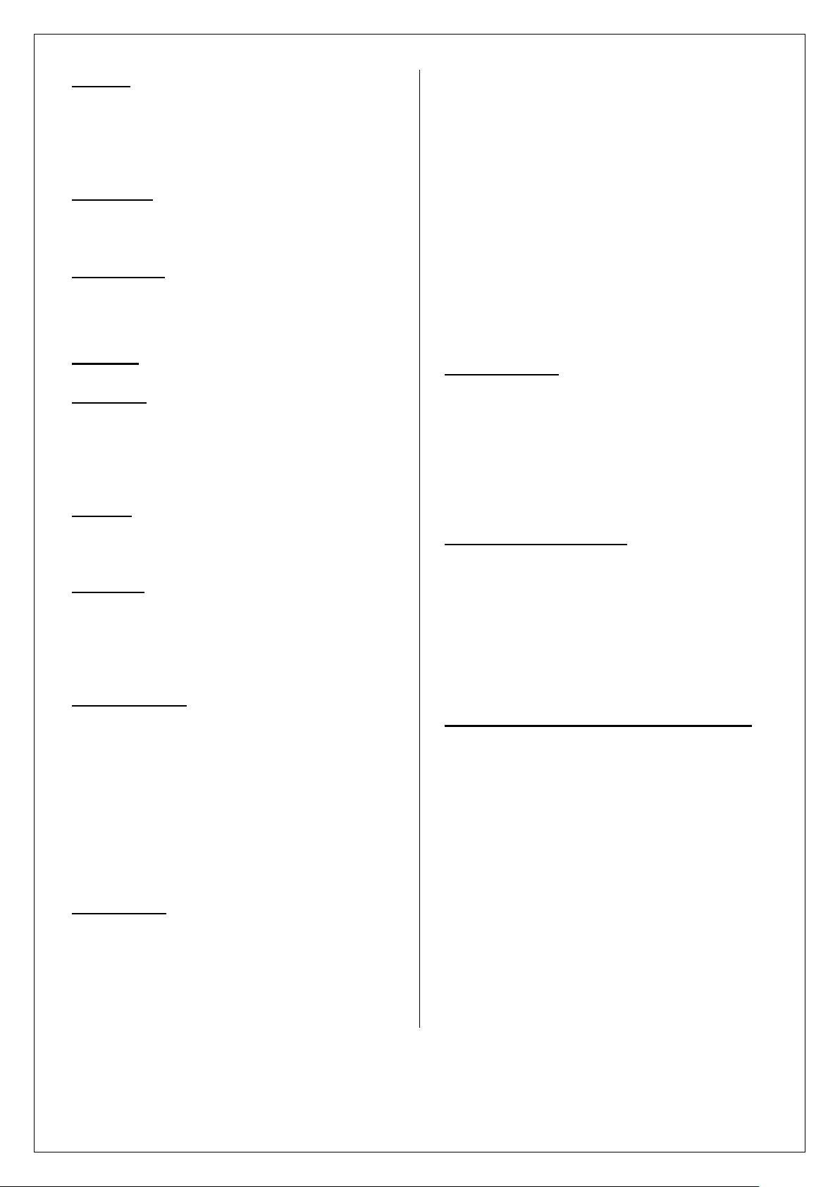
Removing Internal Components
All internal components must be removed prior
to fitting the stove. This will make handling the
stove easier; allow access to fixings and the flue
outlet; as well as protect the internal
components from damage during the installation
process.
1. Open the door(s) and remove the ashpan.
2. Remove the fuel retainer by lifting
upwards of its supports and remove from
firebox.
4. Remove the bricks by sliding forward so
they are clear of their supports and tilting
the bottom edge into the fire box.
5. Remove the grate bars by lifting the front
up off the cam bar and sliding forward off
the rear grate support and lifting out of
the firebox. Repeat with remaining grate
bars.
3. Remove the fuel retainer support (front
plate) by lifting the fuel retainer support
clear from its locating slots. Then remove.
JINTDBW09 Rev B 05/03/15
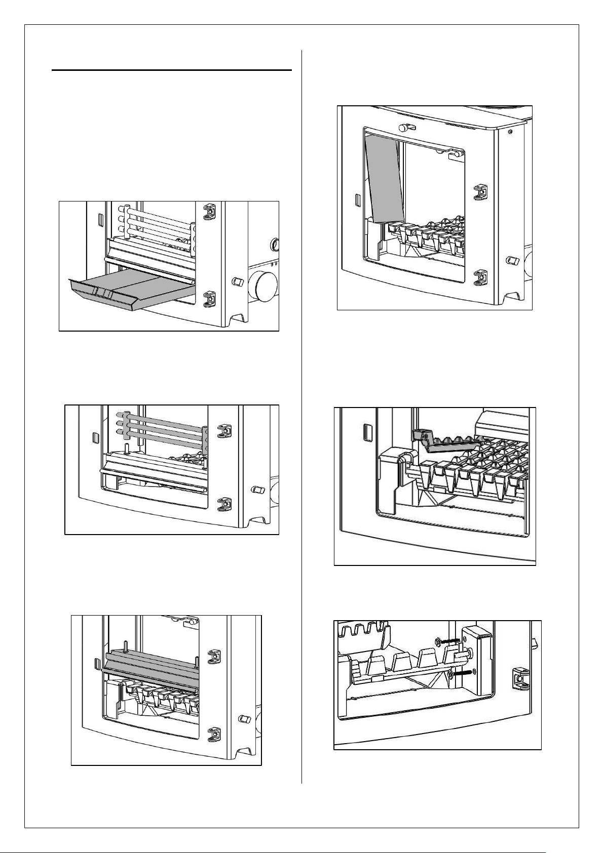
6. Remove cam bar by removing the two M6
x 50mm screws form the cam bar cover.
6
7. Remove the cam bar and cam bar cover
by lifting the cam bar from the left hand
side until clear of the support. Slide the
cam bar to the left and remove.
8.
Remove the rear grate bar support by
lifting the grate bar support clear of the
locating slots and remove.
RE-ASSEMBLING THE STOVE
Refit all the internal parts by following the
‘removing internal components’ instructions in
reverse orders.
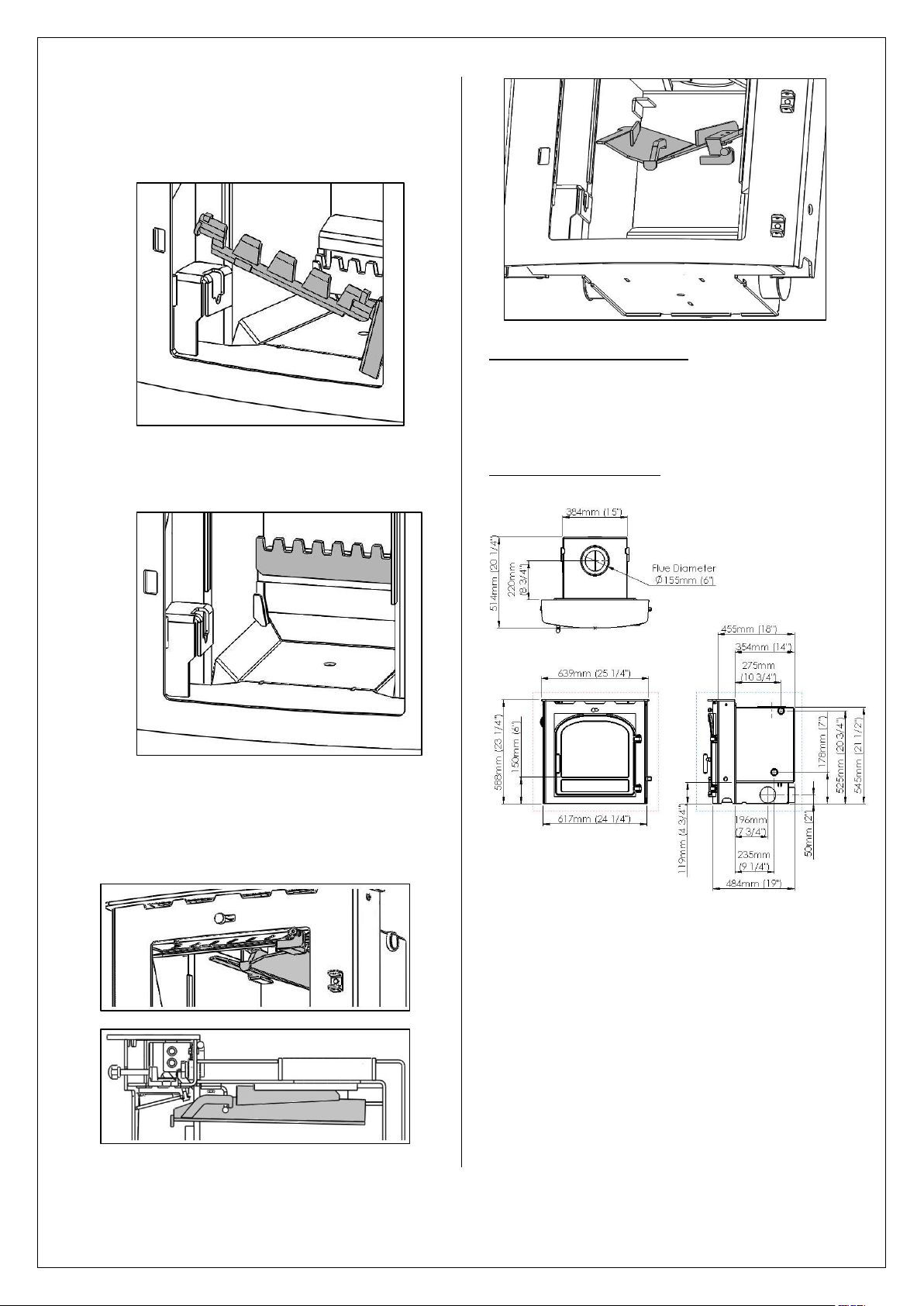
APPLIANCE DIMENSIONS
9. Remove the baffle by sliding it forward
until it reaches its stop. Then lift and slide
forward until clear of its supports and
lower into the firebox.
JINTDBW09 Rev B 05/03/15
7
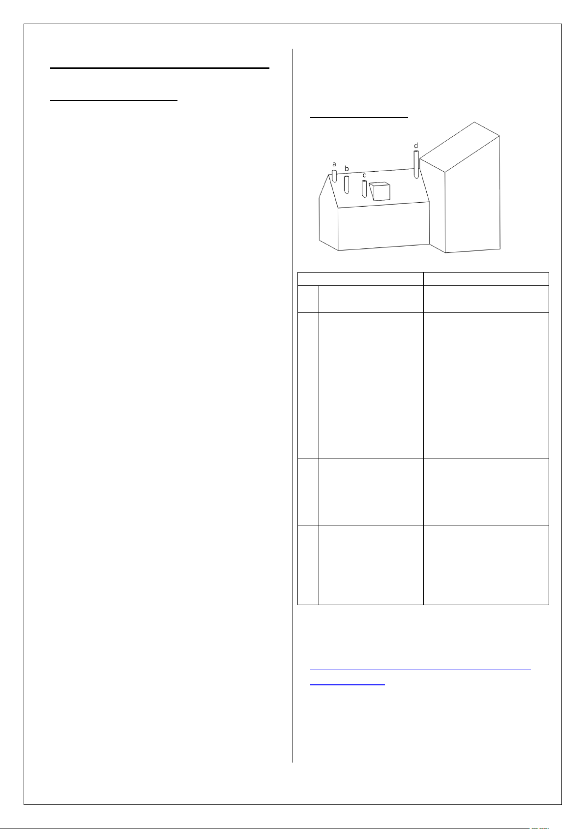
Pre Installation Requirements
Position on Roof
Clearances to flue exit
A
At or within
600mm of the ridge
At least 600mm
above the ridge
B
Elsewhere on a roof
(Pitched or Flat)
At least 2.3 M
horizontally from the
nearest point on the
weather surface and:
a) At least 1.0 M above
the highest point of
intersection between the
chimney and weather
surface; or
b)at least as high as the
ridge
C
Below (on a pitched
roof) or within 2.3 M
horizontally to an
opening window or
dormer
At least 1.0 M above the
top of the opening
D
Within 2.3 M of an
adjoining or
adjacent building,
whether or not
beyond the
boundary
At least 600mm above
any part of the adjacent
building within 2.3 M
PLEASE CHECK THE FOLLOWING:
Any existing chimney/flue system must be
confirmed as suitable for this appliance as defined
in Building Regulations Document J. It must be
swept and inspected, by a competent person (see
notes), to confirm that is structurally sound and
free from cracks and obstructions. The diameter
of the Flue should not be less than Ø150mm and
not more than Ø200mm. Do not connect to
systems that have large voids or spaces. If any of
these requirements are not met, the chimney
should be lined by a suitable method.
If the chimney is suspected of previously serving
an open fire it must be swept again, within a
month of regular use, to clear any soot that may
have been dislodged due to the variation in
combustion levels and higher flue gas
temperature levels. The chimney/flue system exit
must comply with Building Regulations Document
J. The minimum height of the chimney/flue system
must be 4.5 metres and should terminate in
accordance with Table 1.
Make provision to access the chimney/flue system
for cleaning and the removal of debris. If there is
no existing chimney then either a prefabricated
block chimney in accordance with Building
Regulations Approved Document J, or a twinwalled insulated stainless steel flue to BS4543 can
be used. These chimneys must be fitted in
accordance with the manufacturer’s instructions
and Building Regulations. New masonry and flue
block chimneys must meet the requirements of
Building Regulations Document J. Any connecting
flue pipe systems must also meet these
regulations.
Please check the suitability of the fireplace and/or
surround for use with this appliance before
installing it. Many Fire Surrounds are only suitable
for use with gas and electric fires and therefore
may not suitable for this Solid Fuel Appliance.
Please check your Fire Surround. Fire Surround
Back Panels suitable for solid fuel are usually in
three sections and slabbed.
If you have any doubts about the
suitability of your chimney, consult your
local dealer/stockist.
Both the chimney and flue pipe must be
accessible for cleaning and if ANY part of
JINTDBW09 Rev B 05/03/15
the chimney cannot be reached through the
stove (with baffle removed), a soot door
must be fitted in a suitable position.
FLUE OUTLET POSITIONS
Table 1. – Flue Terminal Positions
A full copy of Document J can be found here:
http://www.planningportal.gov.uk/uploads/br/BR
_PDF_ADJ_2010.
8
 Loading...