

Hunter Stoves Telford Inset 20DB CVWSTI08DBFM, Telford Inset 20DB, Telford Inset 20DB CVWTI08DBFM Instructions For Installation/operating/maintenance/servicing
Page 1
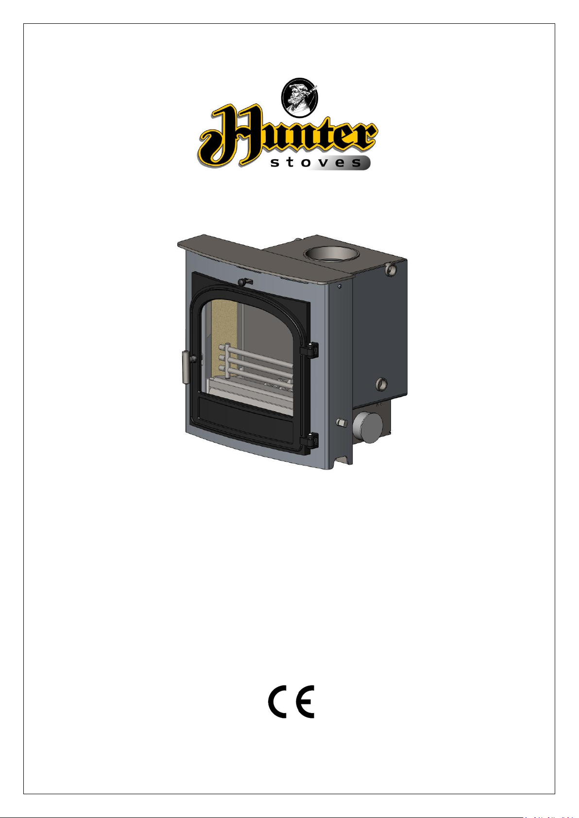
Telford Inset 20DB
Multifuel Boiler Stove
Model: CVWSTI08DBFM/CVWTI08DBFM
Instructions for:
Installation/Operating/Maintenance/Servicing
JINTDBW09 Rev B 05/03/15
Page 2

CONTENTS INDEX:
TECHNICAL SPECIFICATION……………………………………………………………………………………………… 3
IMPORTANT INFORMATION……………………………………………………………………………………………. 4
REMOVING INTERNAL COMPONENTS……………………………………………………………………………… 6
APPLIANCE DIMENSIONS ……………………………………………………………………………………………… 7
PRE INSTALLATION REQUIREMENTS…………………………………………………………………………………. 8
INSTALLATION INSTRUCTIONS………………………………………………………………………………………… 11
INSTALLATION OF HEATING & HOT WATER……………………………………………………………………………. 13
COMMISSIONING AND HANDOVER………………………………………………………………………………….. 15
OPERATING INSTRUCTIONS……………………………………………………………………………………………… 16
MAINTENANCE & SERVICING…………………………………..……………………………………………………….. 19
SPARES INFORMATION……………………………………………………………………………………………………… 21
COMMISSIONING & INSTALLATION CHECK LIST……………..……………….……………………………….. 24
SERVICE RECORDS…………………………………………………………………………………………………………….. 25
Hunter Stoves,
Emperor Way,
Exeter Business Park,
Exeter,
Devon. EX1 3QS
Email info@hunterstoves.co.uuk
Website http://www.hunterstoves.co.uk
WARRANTY
Hunter Stoves appliances come with a standard 2 year warranty; however this excludes naturally
wearing “consumable” components and the use of un-authorised fuels.
Consumables are deemed to be; Glass, Seals, Gaskets, Grate Components, Log Retainers, Baffles,
Thermostat and the surface finish of the appliance.
The Warranty will only be valid if the appliance is installed by an appropriately qualified engineer in
accordance with the manufacturer’s instructions and to the appropriate Building Regulations and/or
Local By-Laws and serviced within 12 months of installation.
Hunter Stoves will also support an extended 5 year warranty on external Cast Iron components such
as Doors, Flue Collars and Covers.
If this appliance is purchased through an un-authorised stockist or an internet trader Hunter Stoves
are only obliged to support the statutory requirements.
This appliance must be regularly serviced and maintained, using only Hunter Stoves approved
components for the Warranty to be valid
JINTDBW09 Rev B 05/03/15
2
Page 3
INSET TELFORD 20DB
Unit 8 Emperor Way, Exeter Business
Park, Exeter, Devon, EX1 3QS
BS/EN 13229
UKAS# 0692
Stove Mass: 127.67kg
NOMINAL OUTPUT: 15.8KW
NOMINAL OUTPUT TO WATER: 10.7KW
NOMINAL OUTPUT TO SPACE: 5.1KW
CO Emission at 13% O2: 0.33%
Mean Flue Gas Temperature: 385°C
EFFICIENCY: 69.9%
Flue Gas Mass Flow: 14.1g/s
Maximum operating water temperature in °C: 100°C
Maximum operating pressure in bar: 1.2 Bar
Minimum clearance to combustible material
Top of Fire Surround:
150mm
Side of Fire Surround:
75mm
Side Wall:
200mm
This appliance is suitable for intermittent burning
This appliance is not suitable for use in a shared flue
Read and follow the operating instructions
Use only recommended fuels
15
Inset Telford 20DB
Technical Specification
JINTDBW09 Rev B 05/03/15
3
Page 4
IMPORTANT INFORMATION
PLEASE READ THESE INSTRUCTIONS PRIOR TO INSTALLATION AND OPERATION.
KEEP THESE INSTRUCTIONS IN A SAFE PLACE FOR FUTURE REFERENCE AND SERVICING.
THIS APPLIANCE WILL BECOME HOT WHEN USED IN ACCORDANCE WITH THESE INSTRUCTIONS.
HUNTER STOVES RECOMMEND THAT AN APPROVED GUARD IS USED TO PROTECT THE YOUNG,
ELDERLY OR INFIRM FROM HARM.
THE INSTALLER COMMISSIONING SHEET CAN BE FOUND ON THE BACK COVER.
PLEASE ENSURE THAT IT IS COMPLETED PRIOR TO USE.
GENERAL GUIDANCE
It is important that your stove is correctly
installed and operated as Hunter Stoves cannot
accept responsibility for any fault arising through
incorrect installation, use, maintenance or
servicing.
These instructions cover the basic principles to
ensure satisfactory installation of the stove,
although detail may need slight modification to
suit particular local site conditions.
The installation must comply with current Building
Regulations, National and European Standards,
Local Authority Byelaws and other specifications
or regulations as they affect the installation of the
appliance.
The Building Regulations requirements may also
be met by adopting the relevant
recommendations in the current issues of British
Standards BS 8303 and BS EN 15287-1.
Only use approved fuels on this appliance.
Information about this can be found on Page 18.
This is a Domestic Appliance and must only be
used in accordance with these instructions.
Do not place articles that are affected by high
temperatures on, or near, this appliance. Do not
place furniture or other items within 700mm of
the front of this appliance. See the note on
material clearances on page 10.
JINTDBW09 Rev B 05/03/15
Extractor Fans and/or Cooker Hoods must not be
installed in the same space or room as this can
cause the appliance to emit fumes into the room.
Do not obstruct the ventilation required for the
safe use of this appliance.
COMPETENT PERSONS SCHEME
Hunter Stoves recommend that this stove is
installed by a member of an accredited
competent persons scheme e.g. HETAS.
If the installer is not a member of a competent
person’s scheme, it is a legal requirement, in the
UK, to notify your Local Building Control Officer in
advance of any installation work starting.
HEALTH AND SAFETY PRECAUTIONS
Special care must be taken when installing the
stove such that the requirements of the Health
and Safety at Work Act are met.
HANDLING
This appliance is very heavy. Adequate facilities
must be available for loading, unloading and site
handling
FIRE CEMENT
Some types of fire cement are caustic and should
not be allowed to come into contact with the skin.
In case of contact, wash immediately with plenty
of water.
4
Page 5
ASBESTOS
This stove contains no asbestos. If there is a
possibility of disturbing any asbestos in the course
of installation then please seek specialist guidance
and use appropriate protective equipment.
METAL PARTS
When installing or servicing this stove, care should
be taken to avoid the possibility of personal injury.
MODIFICATION
No unauthorized modification of this appliance
should be carried out.
SAFETY
WARNING!
This appliance will be hot when in operation and
due care should be taken. The supplied gloves
may be used to open the door and operate the air
controls.
AEROSOLS
Do not use an aerosol spray on or near the stove
when it is alight.
FIREGUARDS
Always use a fireguard in the presence of children,
the elderly or the infirm. The fireguard should be
manufactured in accordance with BS8423 –
Fireguards for use with solid fuel appliances.
DO NOT OVER-FIRE
It is possible to fire the stove beyond its design
capacity. This could damage the stove so watch
for signs of over-firing. If any part of the stove
starts to glow red, the stove is in an over-fire
situation and the controls should be adjusted
accordingly. Never leave the stove unattended for
long periods without first adjusting the controls to
a safe setting. Careful air supply control should be
exercised at all times.
FUME EMISSION
Properly installed and operated, this appliance
will not emit fumes. Occasional fumes from deashing and refueling may occur. Persistent fume
emission must not be tolerated.
This appliance should not be operated with the
door open.
If fume emission does persist then the following
action should be taken immediately;
Open Doors and windows to ventilate room.
Let the fire out, or eject and safely dispose of
fuel from the appliance.
Check for flue/chimney blockage and clean if
required.
Do not attempt to relight the fire until the
cause has been identified and corrected.
If necessary seek professional advice.
ADVERSE WEATHER
In a small number of installations, occasional local
weather conditions (e.g. wind from a particular
direction) may cause downdraught in the flue and
the stove to emit fumes. In these circumstances
the stove should not be used. A professional flue
installer will be able to advise on solutions to this
problem (e.g. anti-downdraught cowl).
CARBON MONOXIDE DETECTOR
Hunter Stoves recommend a Carbon Monoxide
Detector that conforms to the latest issue of BS
EN 50292 is placed in the same room as the
appliance. The installation of such an alarm is not
considered as a substitute for regular
maintenance or servicing or the appliance and
Flue system.
IN THE EVENT OF A CHIMNEY FIRE:
Raise the alarm
Call the Fire Brigade
Close appliance air controls
Move furniture, ornaments etc. away
Place a fireguard in front of stove
Check the chimney breast for signs of excessive
heat.
If the wall is becoming excessively hot, move
furniture away.
Ensure the Fire Brigade can gain access to your
roof space in order to check for fire spread.
JINTDBW09 Rev B 05/03/15
5
Page 6
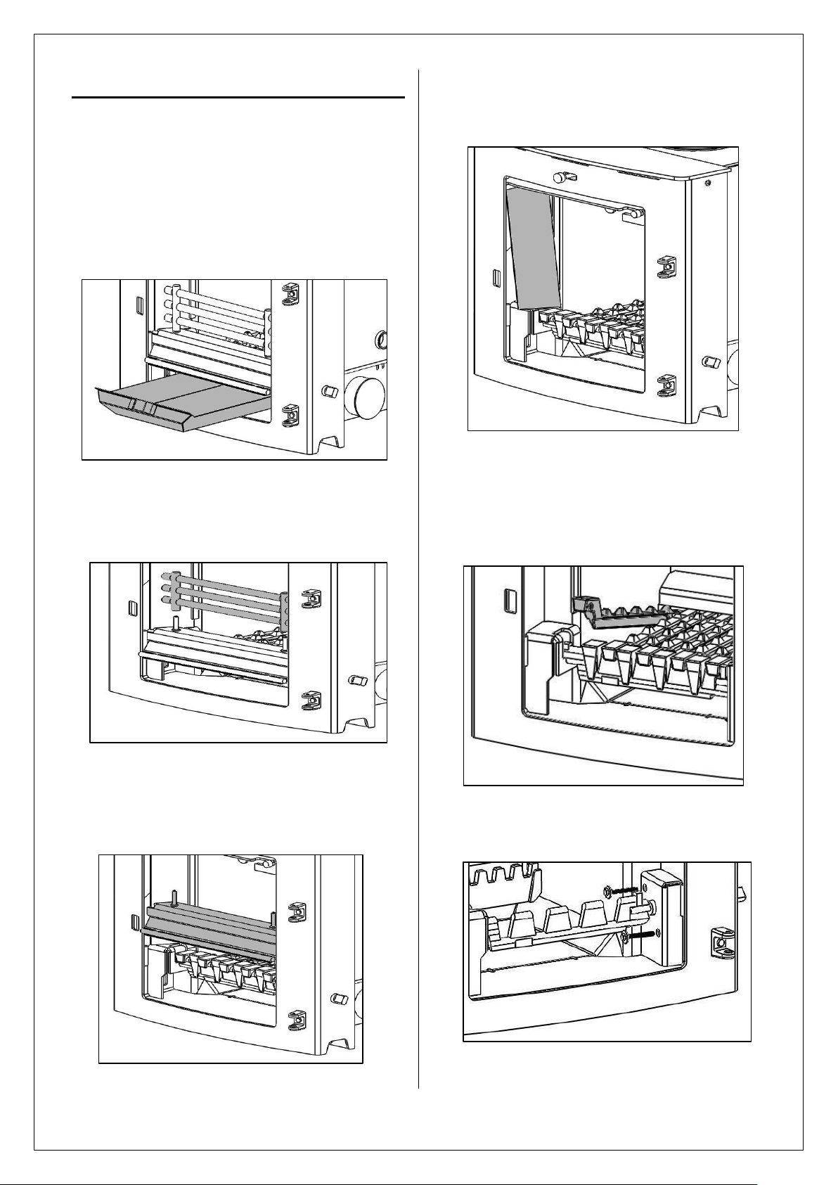
Removing Internal Components
All internal components must be removed prior
to fitting the stove. This will make handling the
stove easier; allow access to fixings and the flue
outlet; as well as protect the internal
components from damage during the installation
process.
1. Open the door(s) and remove the ashpan.
2. Remove the fuel retainer by lifting
upwards of its supports and remove from
firebox.
4. Remove the bricks by sliding forward so
they are clear of their supports and tilting
the bottom edge into the fire box.
5. Remove the grate bars by lifting the front
up off the cam bar and sliding forward off
the rear grate support and lifting out of
the firebox. Repeat with remaining grate
bars.
3. Remove the fuel retainer support (front
plate) by lifting the fuel retainer support
clear from its locating slots. Then remove.
JINTDBW09 Rev B 05/03/15
6. Remove cam bar by removing the two M6
x 50mm screws form the cam bar cover.
6
Page 7
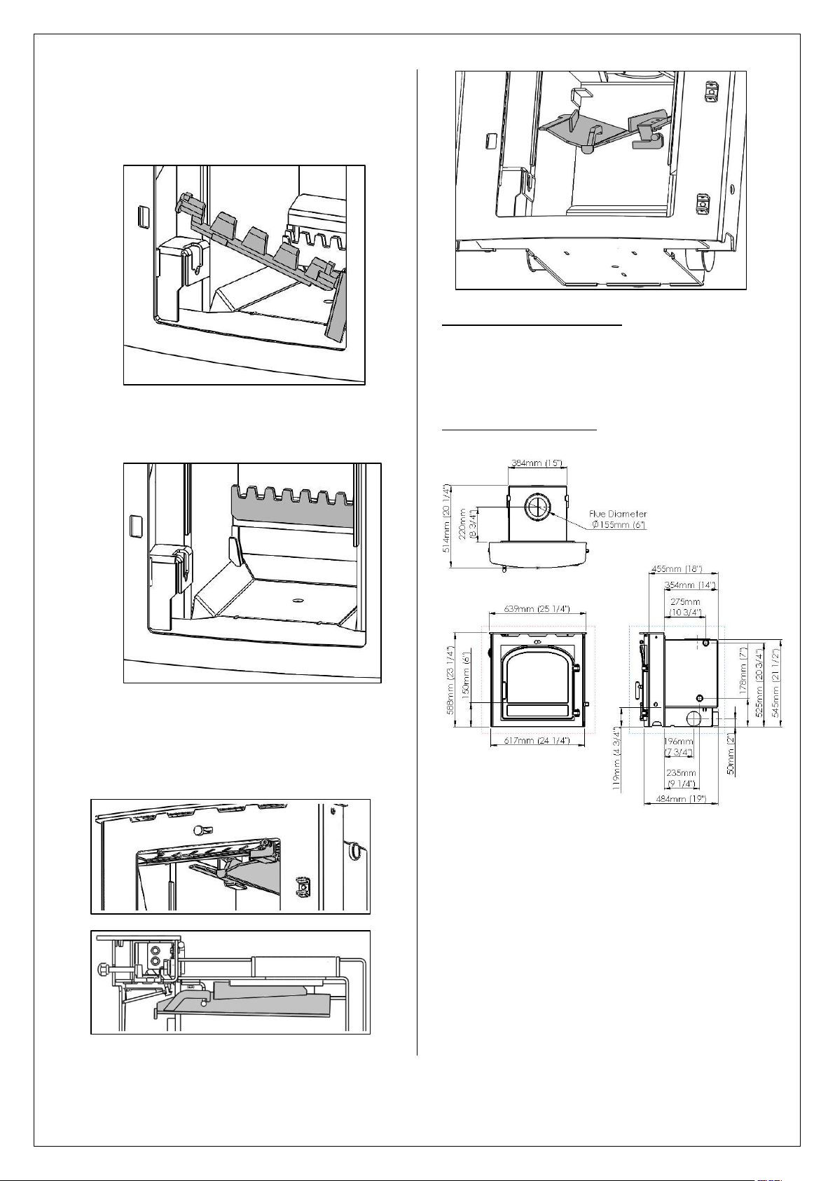
7. Remove the cam bar and cam bar cover
by lifting the cam bar from the left hand
side until clear of the support. Slide the
cam bar to the left and remove.
8.
Remove the rear grate bar support by
lifting the grate bar support clear of the
locating slots and remove.
RE-ASSEMBLING THE STOVE
Refit all the internal parts by following the
‘removing internal components’ instructions in
reverse orders.
APPLIANCE DIMENSIONS
9. Remove the baffle by sliding it forward
until it reaches its stop. Then lift and slide
forward until clear of its supports and
lower into the firebox.
JINTDBW09 Rev B 05/03/15
7
Page 8
Pre Installation Requirements
Position on Roof
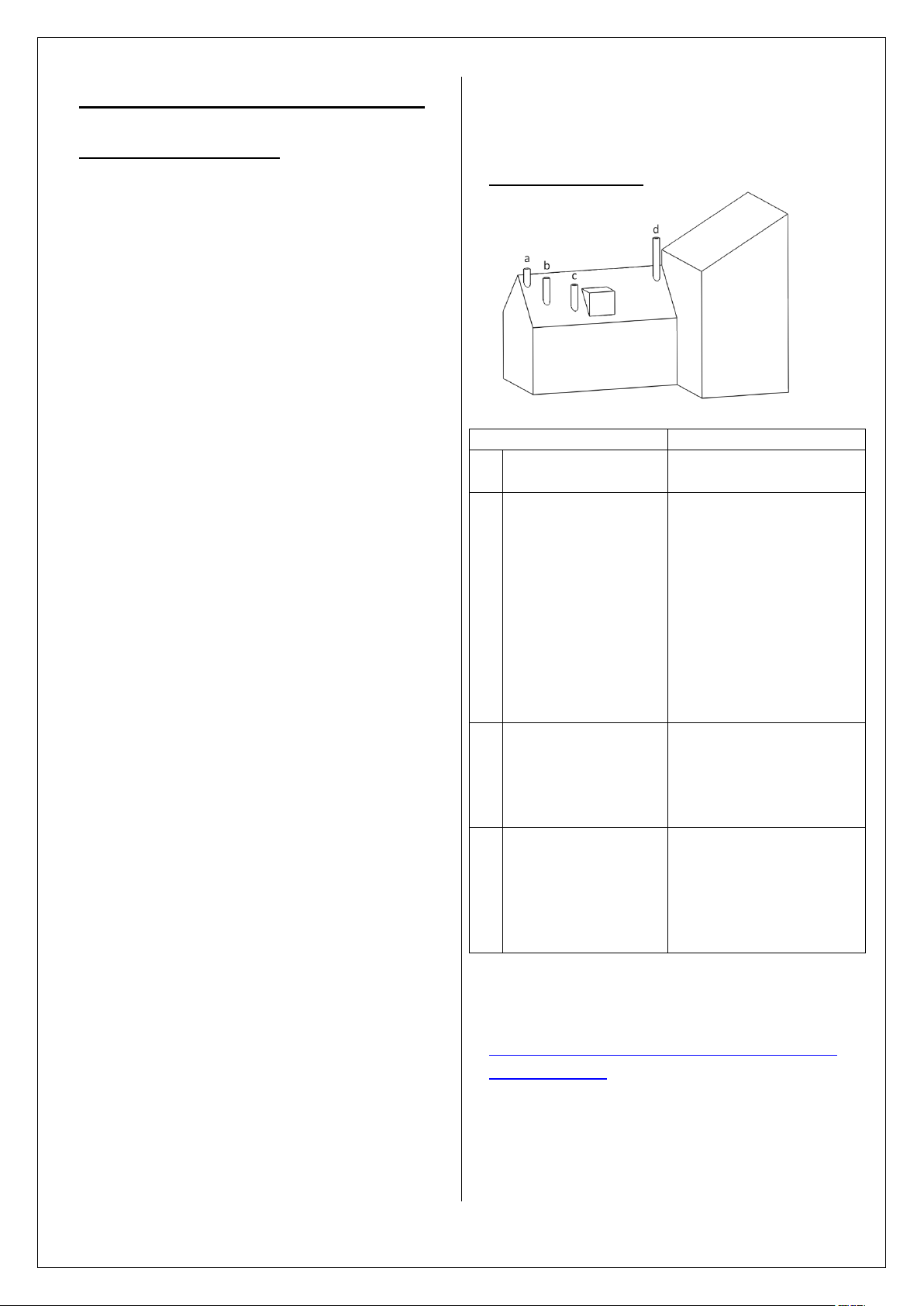
Clearances to flue exit
A
At or within
600mm of the ridge
At least 600mm
above the ridge
B
Elsewhere on a roof
(Pitched or Flat)
At least 2.3 M
horizontally from the
nearest point on the
weather surface and:
a) At least 1.0 M above
the highest point of
intersection between the
chimney and weather
surface; or
b)at least as high as the
ridge
C
Below (on a pitched
roof) or within 2.3 M
horizontally to an
opening window or
dormer
At least 1.0 M above the
top of the opening
D
Within 2.3 M of an
adjoining or
adjacent building,
whether or not
beyond the
boundary
At least 600mm above
any part of the adjacent
building within 2.3 M
PLEASE CHECK THE FOLLOWING:
Any existing chimney/flue system must be
confirmed as suitable for this appliance as defined
in Building Regulations Document J. It must be
swept and inspected, by a competent person (see
notes), to confirm that is structurally sound and
free from cracks and obstructions. The diameter
of the Flue should not be less than Ø150mm and
not more than Ø200mm. Do not connect to
systems that have large voids or spaces. If any of
these requirements are not met, the chimney
should be lined by a suitable method.
If the chimney is suspected of previously serving
an open fire it must be swept again, within a
month of regular use, to clear any soot that may
have been dislodged due to the variation in
combustion levels and higher flue gas
temperature levels. The chimney/flue system exit
must comply with Building Regulations Document
J. The minimum height of the chimney/flue system
must be 4.5 metres and should terminate in
accordance with Table 1.
Make provision to access the chimney/flue system
for cleaning and the removal of debris. If there is
no existing chimney then either a prefabricated
block chimney in accordance with Building
Regulations Approved Document J, or a twinwalled insulated stainless steel flue to BS4543 can
be used. These chimneys must be fitted in
accordance with the manufacturer’s instructions
and Building Regulations. New masonry and flue
block chimneys must meet the requirements of
Building Regulations Document J. Any connecting
flue pipe systems must also meet these
regulations.
Please check the suitability of the fireplace and/or
surround for use with this appliance before
installing it. Many Fire Surrounds are only suitable
for use with gas and electric fires and therefore
may not suitable for this Solid Fuel Appliance.
Please check your Fire Surround. Fire Surround
Back Panels suitable for solid fuel are usually in
three sections and slabbed.
If you have any doubts about the
suitability of your chimney, consult your
local dealer/stockist.
Both the chimney and flue pipe must be
accessible for cleaning and if ANY part of
JINTDBW09 Rev B 05/03/15
the chimney cannot be reached through the
stove (with baffle removed), a soot door
must be fitted in a suitable position.
FLUE OUTLET POSITIONS
Table 1. – Flue Terminal Positions
A full copy of Document J can be found here:
http://www.planningportal.gov.uk/uploads/br/BR
_PDF_ADJ_2010.
8
Page 9

LEGAL REQUIREMENTS
Scheme
Web address
Telephone
APHC (Association
of Plumbing and
Heating
Contractors
(Certification)
Limited
www.aphc.co.uk
0121 711 5030
Building
Engineering
Services
Competence
Accreditation
(BESCA Limited)
www.hvca.org.uk /
www.besca.org.uk
0800 652 5533
HETAS Ltd
(Heating
Equipment Testing
and Approval
Scheme)
www.hetas.co.uk
01684 278170
NAPIT Registration
Ltd
www.napit.org.uk
01623 811483
NICEIC Group Ltd
www.niceic.com
0870 013 0389
Hunter Stoves requests that before installation
and/or use of this appliance that you read these
instructions carefully to ensure that all the
relevant requirements are fully understood.
These instructions cover the basic principles to
ensure satisfactory installation of the stove,
although detail may need slight modification to
suit particular local site conditions. In all cases
the installation must comply with current Building
Regulations, Local Authority Byelaws, European
and National Standards and other specifications
or regulations as they affect the installation of the
stove.
It should be noted that the Building Regulations
requirements may be met by adopting the
relevant recommendations given in British
Standards BS 8303, BS 6461 and BS 7566 as an
alternative means to achieve an equivalent level
of performance to that obtained following the
guidance given in Approved Document J.
Your local Building Control Officer can advise you
regarding the interpretation of the Regulations
should there be any questions.
This appliance must be installed by a Registered
Installer (see Competent Persons Scheme) or
approved by your local Building Control Officer.
All works undertaken must be carried out with
due care and attention to meet the requirements
of the Health & Safety code of practice and any
other legislation that may have been introduced
since the publication of these instructions.
COMPETENT PERSONS SCHEME
Members of the following schemes may selfcertify the installation of this stove. If the installer
is not a member of one of these schemes, your
local Building Control Department must approve
the installation.
AIR SUPPLY
The room or space containing this appliance
should have purpose provided ventilation (where
necessary) in accordance with Building
Regulations.
Due consideration should be given to air
requirements for any other appliance in the same
room or space.
Any air opening must be kept clear from blockage
or obstruction.
This stove must be fitted on a hearth or base with
adequate load-bearing capacity.
APPLIANCE OPENING
The opening into which this stove is fitted should
be constructed wholly from non-combustible
materials. The dimensions of the opening should
be at least those shown in the diagrams on page
10.
JINTDBW09 Rev B 05/03/15
9
Page 10

This appliance will fit into a standard 16” fireplace
opening if the clay fire back is removed.
Any non-combustible walls within 50mm of this
appliance should be at least 200mm thick and
should extend at least 30mm above the top of
the appliance and at least 1.2 metres above the
hearth. Any walls more than 50mm from the
appliance may be reduced to a thickness of
75mm. Ensure the inter-connecting flue pipe also
has adequate clearances to combustible
materials
The walls surrounding the stove will become hot
and should therefore be finished in a heat
resistant plaster.
Do not hang pictures, plasma screen televisions
or ornaments above the stove, as these could be
damaged and could potentially create a fire
hazard.
HEARTH REQUIREMENTS
A constructional hearth with a minimum thickness
of 125mm should be provided. This constructional
hearth should extend to at least 300mm in front
of the stove and 150mm at the sides
The constructional hearth should be made of solid
non-combustible material and can include any
solid non-combustible floor. The boundary of the
hearth must be clearly marked. This can be done
by adding a super-imposed hearth on top of the
constructional hearth – e.g. a slate slab on top of a
solid concrete floor.
FLUE DRAUGHT
If the draught exceeds the recommended
maximum, a draught stabiliser must be fitted so
that the rate of burning can be controlled and to
prevent over firing.
If the reading is less than the recommended
minimum then the performance of the appliance
will be compromised.
The flue draught should be checked under fire at
high output.
Minimum Draught – 1.2mm Water Gauge
Maximum Draught – 2.5mm Water Gauge
CLEARANCES TO COMBUSTIBLE MATERIALS
Excluding some fire surround installations (see
below) there should be no combustible material
within 200mm of either side of the stove or
275mm above.
No combustible furniture should be placed any
closer than 700mm from the front of the stove.
JINTDBW09 Rev B 05/03/15
10
Page 11

FIRE SURROUNDS
Rope Seal
Please check the suitability of any
fireplace/surround for closed solid fuel
appliances before installation.
Hunter Stoves cannot be held responsible for any
fault arising through incorrect use or installation.
Fire surround back panels suitable for solid fuel
are usually in three sections and slabbed. Many
fire surrounds are suitable only for use with gas
and electric fires and therefore not suitable for
solid fuel.
A combustible fire surround with a depth of up to
100mm requires a minimum clearance of 75mm
from the side of the stove. For combustible fire
surrounds with a depth in excess of 100mm this
clearance must be increased to 200mm.
Installing the Stove
1. Check positions of pipe connections.
2. Make suitable access holes so you can access
the tappings and infill with vermiculite
concrete.
3. Apply fire cement around the rope seal. This
will help seal the stove when in position.
4. Move the stove into position inside the
fireplace opening, being careful not to
damage the hearth or paintwork on the stove
and making sure that the rope seal is
compressed forming a tight seal between the
stove and fireplace.
5. Drill hole into hearth through base using a
10mm drill bit.
6. Position anchor bolt provided through base
plate and fix stove in place.
7. Connect the boiler – see ‘Installation of boiler
models’.
8. Fill the boiler and check for leaks.
9. Connect the flue – see ‘Flue connection’.
10. Infill around the stove with vermiculite
concrete.
11. Fill in the access for the boiler pipe
connections.
12. Fill in the top access.
11
JINTDBW09 Rev B 05/03/15
Page 12

FLUE CONNECTION
N.B. An adjustable flue bend may be required for
some installations.
If connecting to a stainless liner, a proprietary
single wall flue adaptor will be required. It is
recommended that a short length of flue pipe is
connected before the liner.
Alternatively a connection can be made using a
register plate although it will be necessary to allow
access for fitting the flue pipe to the register plate,
infilling with vermiculite concrete and sealing all
joints.
If connecting to an existing masonry chimney it is
recommended that a flue forming pipe (short
length of flue pipe) is used and the void between
the flue forming pipe and the chimney is filled with
vermiculite concrete.
A suitable access hole will need to be made in the
chimney breast to allow the back filling to be
carried out and then filled and sealed once the
installation is complete.
JINTDBW09 Rev B 05/03/15
12
Page 13

INSTALLATION OF HEATING & HOT WATER SYSTEM
We strongly recommend that a knowledgeable,
experienced and qualified plumbing and heating
engineer is responsible for the design and
installation of the heating and hot water system.
Hunter Stoves Ltd cannot accept responsibility for
any consequential loss, however caused, due to
under or over specification of the appliance in any
installation.
Do Not – Under any circumstances connect the
stove to a sealed (pressurised)
heating system or unvented hot water
cylinder.
Do Not – Link the stove into a heating or hot
water system with an existing boiler
without the use of suitable equipment
such as a neutralizer. When fitting this
type of system the neutralizer
manufacturer’s instructions must be
followed.
Do – Fit an open cold feed and expansion
cistern with separate cold feed and
vent pipes. The cold feed and vent
pipes must be unvalued. The open vent
pipe should have a diameter of 22mm
and rise continuously from the boiler.
It is common practice to form the vent
pipe from an extension of the primary
flow (see diagram).
If a common flow and return is used, these should
also be taken from diagonally opposite sides of
the boiler, and plugs inserted into the sockets not
used.
Systems using a common flow and return to the
boiler should incorporate an injector tee on the
primary return connection from the central
heating pump (see diagram).
A HIGH LIMIT thermostat should be fitted to the
gravity flow pipe close to the boiler and set at
90°C. This should override any pump control,
switching the pump on and dissipating any excess
heat around the radiator circuit.
To prevent boiler corrosion due to condensation it
is necessary to maintain the return water
temperature above 45°C. This can be achieved by
the use of a LOW LIMIT thermostat on the return
pipe from the hot water cylinder, close to the
boiler. The thermostat should make on
temperature rise, preventing the circulating pump
from operating until the gravity circuit is up to
temperature.
Do – Connect the stove to a double feed,
indirect hot water cylinder via 28mm
copper flow and return pipe work,
rising continuously from the boiler to
the cylinder. The cylinder and heat leak
radiator must be sited higher than the
stove.
Semi pumped systems should be used on heating
and hot water systems with gravity circulation to
the hot water cylinder and one unvalved 2 KW
radiator to act as a heat leak when the central
heating is switched off.
All four tappings on wraparound boilers should be
used for systems incorporating separate gravity
and pumped heating loops. Each flow and return
should be taken from diagonally opposite sides of
the boiler.
JINTDBW09 Rev B 05/03/15
13
Page 14

Room Thermostat
High Limit
Thermostat
90°C
Circulating Pump
Low Limit Thermostat (45°C)
Time Switch
Drain Cock
Room Thermostat
High Limit
Thermostat
90°C
Circulating Pump
Low Limit Thermostat (45°C)
Time Switch
Drain Cock
Injector Tee
Four Tapping System
Two Tapping System
Wiring Diagram for general guidance only
All electrical work must be carried out by a
competent electrician in accordance with the
rules in force and the instructions provided by
the circulating pump and heating controls
manufacturer
Central Heating Control
JINTDBW09 Rev B 05/03/15
14
Page 15

Commissioning and Handover
APPLIANCE CHECK
Please check that all components are correctly
assembled and working correctly.
Ensure the Air Controls are working correctly.
Hunter Stoves recommend that you carry out a
smoke draw test to check the soundness of the
chimney/flue system and seals:
Place a Smoke Pellet in the centre of the Grate,
ensure that all of the Air Controls are fully open
and close the Door.
The smoke should now be drawn up the chimney
and you should be able to see it exit from the
chimney/flue terminal.
We recommend that you do this test with all of
the windows and doors, to the room where the
appliance is fitted, closed.
If there any adjoining room(s) that have an
Extractor Fan fitted, open the adjoining door to
ensure that the chimney/flue system is not
compromised when the fan is operating.
If there is a ceiling fan fitted in the room please
operate it and ensure that it does not affect the
operation of the chimney/flue system.
If any of these tests fail, please re-check the
suitability of the chimney/flue system together
with the ventilation.
A small fire can now be lit and allow the appliance
to heat up slowly ensuring that no products of
combustion enter into the room.
When the appliance has reached working
temperature open the door, move the Baffle to
the re-fuelling position (see instructions on page
17), and carry out a spillage test using a smoke
match around the door opening.
If there is excessive spillage please allow the
appliance to cool and then re-check the
chimney/flue system and ventilation.
Do not run the stove at full output for at least 24
hours.
On completion of the commissioning:
Upon completion, allow a suitable period of time
for any fire cement and mortar to dry out. Do not
run the stove at full output for at least 24 hours.
Please instruct the user on the safe operation of
this appliance, how the controls work and basic
maintenance requirements.
Ensure that the operating instructions and
appliance tools are left with the customer and the
check lists have been filled out correctly.
Please advise the customer on the correct use of
the appliance with the fuels likely to be used on
the stove and warn them to use only the
recommended fuels for the stove.
Advise the user on what to do should smoke or
fumes be emitted from the stove.
The user should be warned to use a fireguard to
BS 6539 in the presence of children, aged and/or
infirm persons.
Hunter Stoves also recommend that a CO alarm is
fitted into the room where the appliance is
located.
JINTDBW09 Rev B 05/03/15
15
Page 16

Operating Instructions
SHUT
OPEN
Read the ‘General Guidance’ Section at the start
of these instructions before operating your stove
for the first time.
Allow sufficient clearance between the stove and
pictures, plasma screen televisions or ornaments
etc, as these could be damaged and could
potentially create a fire hazard (For more
information read the ‘Material Clearance’ section
of these installation instructions).
WARNING – This appliance will be hot when in
operation and due care should be taken. The
supplied operating tool or gloves may be used to
open the door and operate the air controls.
USING THE APPLIANCE FOR THE FIRST TIME
We recommend that the appliance is left for 24
hours after installation to allow the fire cement,
fixing glues, etc. to cure.
We also recommend that you have two or three
small fires before you operate your stove to its
maximum heat output. This is to allow the paint to
cure in steadily and to give a long service life of the
paint finish.
During this curing in process you may notice an
unpleasant smell. It is non-toxic, but for your
comfort we would suggest that during this period
you leave all doors and windows open.
AEROSOLS
Do not use an aerosol spray on or near the stove
when it is alight.
AIR CONTROLS
This stove has been designed to burn cleaner and
more efficiently than a conventional stove. If used
correctly this stove will burn far more efficiently
than normal, with the obvious notable feature of
CLEAN GLASS.
For this product to work properly it must be used
correctly. It is essential that the stove has an
adequate air supply for combustion and
ventilation. The primary and secondary air inlets
must be kept clear from obstruction and blockage.
JINTDBW09 Rev B 05/03/15
THERMOSTAT (PRIMARY AIR)
The thermostat is controlled by the knob on the
side of the stove with settings from 0 - 10. The
thermostat generally operates between 50° to 90°.
Experiment with the settings to find the desired
temperature.
SECONDARY AIR
Secondary air is controlled via the slider above the
door(s), it is this “Airwash” that keeps a clean and
uninterrupted view of the fire.
BAFFLE OPERATION
Your Hunter Stove if fitted with a sliding baffle.
The baffle needs to be slid into its open position
when lighting and re-fuelling your stove. This will
prevent spillage while the stove door is open.
To slide the baffle forward you will need to use the
tool provided. Hook the tool onto the tab at the
front of the baffle and pull forward until it hits the
stop. This will create a 30mm gap at the back of
firebox.
16
Page 17

LIGHTING
Baffle in Closed
Position. Hook
Tool on Tab.
Baffle in Open
Position. Slide
Forward until Stop.
Baffle Arm.
Slide the baffle into its open position (see Baffle
Operation below) and open secondary air control
fully and light one or two firelighters placed
centrally on the grate, allowing the flames to
become established before placing several pieces
of small dry kindling in a criss-cross fashion above
the firelighters, taking care not to smother the fire.
Close the stove door. Once the kindling is well
alight open the door and build the fire by gradually
adding fuel, closing the door afterwards.
Once the fire is established gradually close the
secondary air control until around 20% open
(slide control to your left) and add more fuel as
necessary.
When the stove is up to operating temperature
the operating tool or gloves should be used to
operate the air controls.
The baffle will automatically slide back into its
closed position when the door is closed. This is
achieved by the door pushing onto the baffle arm.
LOCOMOTIVE GRATE
Your Hunter Stove is fitted with a locomotive type
grate. So that de-ashing can be carried out cleanly
and easily, it is riddled from the outside of the
stove with the doors closed.
GRATE OPERATION & BURNING SOLID MINERAL FUELS
It is important that the riddling tool is used to
remove the ash to ensure airflow through the fire
bed and allow the fire to burn over the entire area
of the grate. The ashpan should be emptied at
least daily and ash should never be allowed to
build up over a period of time as this will result in
damage to the fire bars. The flat end of the
riddling tool can be used to carry the ashpan.
LOADING THE APPLIANCE (SOLID MINERAL FUEL)
Solid mineral fuel should not be stacked higher
than the top of the fuel retainer as this may result
in damage to the stove.
With a full load of fuel, the stove will need to be
refuelled approximately once every 4 hours.
AIR CONTROLS (SOLID MINERAL FUEL)
Solid mineral fuel burns most efficiently with the
secondary air control around the 20% open position.
Always de-ash before refuelling and do not let the
ash level reach the underside of the grate bars.
Solid mineral fuel produces ash, which if allowed
to build-up will stifle the airflow through the
Primary air inlets and grate. This will eventually
cause the fire to die.
With some solid mineral fuels a residue of burnt
fuel or clinker will accumulate on the grate, allow
the fire to go out periodically to remove this.
IMPORTANT!
We cannot stress firmly enough how important it
is to empty the ashpan regularly. Air passing
through the fire bed cools the grate bars.
Distortion or burning out the grate bars is nearly
always caused by ash being allowed to build up to
the underside of the grate.
JINTDBW09 Rev B 05/03/15
17
Page 18

EXTENDED BURNING (SOLID MINERAL FUEL)
The stove can be banked up for extended burning.
When burning solid fuel, empty the ashpan. Open
air controls and let the fire burn brightly for a
short period. Refuel and close both air controls,
the exact setting required will depend on the fuel
used and the chimney draw so some practice may
be necessary. To revive the fire, open the air
controls until the fire is burning brightly de-ash if
necessary and refuel. Set air controls as required.
Never leave the stove unattended until you are
certain that the flames are fully established.
Should the fire fail to light correctly open the door
and use a poker to spread the fuel across the
bottom of the firebox. Close the door and allow
the fuel and stove to cool before attempting to
relight the fire.
REDUCED COMBUSTION
In order to shut down the stove, reduce the
thermostat control to ‘0’ and close the secondary
air by sliding control to the left. If the controls are
left in this position, the fire will be starved of air
and will die down. If you want to revive the fire it
is recommended that the thermostat control is
opened first, and then the secondary air control.
Warning! - The stove will remain hot for a
considerable time after the fire has been
extinguished.
REFUELLING
When the fuel has burnt down to the fire bed, add
new fuel. The air controls should not need
adjusting while refuelling.
When refuelling it is important to slide the baffle
into its open position to reduce any spillage. (see
Baffle Operation) The baffle will be hot when
refuelling so due care should be taken.
RECOMMENDED FUELS
Hunter Stoves recommend that approved
smokeless fuels are burnt in this appliance.
Only authorised smokeless fuels may be used in
smoke control areas.
Warning! - Petroleum coke fuels (e.g coal) or
household waste must not be burnt on this
appliance. This appliance must not be used as an
incinerator.
Burning wet or unseasoned wood will create tar
deposits in the stove and chimney and will not
produce a satisfactory heat output.
Should any difficulties arise over fuel quality or
suitability, consult your local approved coal
merchant or:
HETAS Ltd – Telephone 01242 673257 –
www.hetas.co.uk
Solid Fuel Association – Telephone 0800 600 000
– www.solidfuel.co.uk
JINTDBW09 Rev B 05/03/15
18
Page 19

MAINTENANCE & SERVICING
WARNING!
NO unauthorised modification of this appliance
should be carried out.
IMPORTANT!
In order to ensure continued compliance with
current Building Regulations and Local Authority
Byelaws, this appliance requires regular
maintenance by a competent person. N.B. Refer to
the ‘Removing Internal Components’ section of the
installation instructions for details on how to
remove each component.
PERIODS OF PROLONGED NON-USE
If the stove is to be left unused for a prolonged
period, then it should be given a thorough clean to
remove ash and unburned fuel residues. To enable
a good flow of air through the appliance to reduce
condensation and subsequent damage, leave the
air controls fully open. If the appliance has been
unused for a long period, such as during the spring
and summer months, a competent person should
check the chimney for potential obstructions
before lighting the stove i.e. get the chimney
swept before the start of the heating season.
BAFFLE
This should be removed and cleaned at least once
a month to prevent any build-up of soot or fly ash
that could lead to blocked flue ways and
dangerous fume emission. If the baffle is removed
the chimney/flue way can be swept through the
appliance.
STOVE BODY
The stove is finished with a heat resistant paint
and this can be cleaned with a soft brush. Do not
clean whilst the stove is hot; wait until it has
cooled down. The finish can be renovated with a
propriety high temperature stove paint.
GLASS PANEL(S)
Clean the glass panel when cool with a propriety
glass cleaner. Highly abrasive substances should
be avoided as these can scratch the glass and
make subsequent cleaning more difficult. Wet
logs on heated glass, a badly aimed poker or
heavy slamming of the doors could crack the glass
panels. The glass will not fracture from heat.
Should you need to replace a glass panel please
ensure you purchase a new Gasket at the same
time. Please check periodically that the glass clips
and screws have not become loose.
GASKETS
All gasket used on this appliance are produced
from a heat resistant material called Manniglas.
Over time you may find that the gasket changes
colour. This is due to a reduction in the pigment
used in the manufacture of the product, and is no
cause for concern
FIREBRICKS
In normal use, these can last for many years. It is
possible however, to crack them if logs are
continually jammed against them or if they are
frequently struck with a poker. Check periodically
for seriously cracked bricks, which can be replaced
with new; available from your dealer or our spares
website www.hunterstoves.co.uk.
DOOR CATCH
Should the door catch require adjustment, please
use the follow procedure: Open the Door. Slacken
the M6 grub screw, on the underside of the
Handle Boss. Turn the inside catch shaft one turn
clockwise, this will achieve a tighter lock when the
door is closed. Re-tighten the M6 grub screw.
Close and test the operation of the Handle
mechanism.
ROPE
Check the 12mm rope around the door. If rope is
becoming detached, use Hunter Stoves rope glue
to reattach it. If the rope is in a poor condition, a
replacement rope kit may be ordered from the
Hunter Stoves spares range.
CHIMNEY & FLUE WAYS
It is important that the chimney, flue ways and
any connecting flue pipe are swept regularly. This
means at least once a year for smokeless fuels and
at least twice a year for wood and other fuels.
The baffle will need to be removed from its
supports in order to sweep the chimney. Only
wire-centred sweeps’ brushes fitted with a guide
wheel should be used. If it is not possible to sweep
all parts of the chimney through the appliance,
ensure there is adequate access to cleaning doors.
If the stove is fitted in place of an open fire, then
the chimney should be swept one month after
installation to clear any soot falls which may have
occurred due to the difference in combustion
between the stove and the open fire.
JINTDBW09 Rev B 05/03/15
19
Page 20

ANNUAL SERVICE
Hunter Stoves recommend that this appliance is
serviced annually, preferably prior to the start of
the heating season, thus avoiding any delay in
receiving replacement components, should you
need them. If you are unable to undertake this
task, Hunter Stoves recommend that you contact
the installation engineer for advice.
Remove all the internal components:
Riddling Bars, Cam Bar, Catch Bar, Ashpan, Side
Plates and Baffle. Clean them with a wire brush
and inspect them for damage.
Sweep the chimney/flue system if necessary.
Clean down the internal surfaces of the appliance
using a scraper or wire brush.
Inspect these surfaces for damage.
If damage is found we advise that you consult with
your installer about rectification/repair.
Brush out or vacuum the inside of the appliance
and re-fit the internal components.
Inspect the Glass and Gasket. Clean the Glass with
a non-abrasive cleaner if required. If the Gasket is
torn or damaged we recommend that is replaced.
Brush down the outer surface and touch up the
paint if necessary.
Burn the appliance at a low rate, after
maintenance, to allow any new seals, paint or glue
to cure properly. The appliance may emit
unpleasant odours during this process, please
ensure the room is well ventilated.
TROUBLESHOOTING:
Incorrect Flue Draught in your chimney/flue
system will cause poor performance of your
appliance. Excessive Flue Draught can cause low
heat output/ Poor burning control, excessive fuel
consumption and even noise from the Air
Controls. Low Flue Draught can cause difficulty in
lighting and running the appliance, poor heat
output and smoke entering the room when the
Appliance Door is opened.
Poor quality Solid Mineral Fuel and/or damp wood
will also affect the performance of your appliance.
Please be aware of the possible warning signs that
your appliance is not functioning correctly.
Poor combustion, staining or sooting around the
appliance, condensation or dampness on walls or
windows in the room where the appliance is
fitted, a strange smell when the appliance is lit or
water leaking from the appliance.
Please consult with your installer if you are
concerned in any way about the performance of
this appliance.
TROUBLESHOOTING EXAMPLES:
FIRE WILL NOT BURN
Check that:
1. The air inlet is not obstructed in any way.
2. Chimneys and flue ways are clear.
3. A suitable fuel is being used.
4. There is an adequate air supply into the
room.
5. An extractor fan is not fitted in the same
room as the stove.
6. Flue draught is above minimum level (see
installation instructions).
FIRE BLAZING OUT OF CONTROL
Check that:
1. The doors are tightly closed.
2. The air controls are all in the closed
position.
3. A suitable fuel is being used.
4. The glass retaining clips are not loose.
5. The door rope seals are in good condition
Flue draught is below maximum level (see
installation instructions).
JINTDBW09 Rev B 05/03/15
20
Page 21

Spares Information
SINGLE DOOR
HCE09008
DOOR HANDLE
ASSEMBLY
TDI05ARRT011MB
DOOR GLASS
HCE09102
ROPE SEALING KIT
SCPCB900SDRSKREVC
GLASS GASKET
HCE09101
GLASS CLIP
HHR08046
SCREW
FSJM05008SS
SINGLE DOOR
JINTDBW09 Rev B 05/03/15
21
Page 22

LEFT HAND DOOR
TDI05008
DOOR GLASS
HCE09031
ROPE SEALING
SCPCB900DRSK
GLASS GASKET
HCE09030
GLASS CLIP
HHR08046
SCREW
FSJM05008SS
RIGHT HAND DOOR
HCE09009
DOOR HANDLE
ASSEMBLY
TDW09ARRT011MB
GLASS CLIP
HHR08046
SCREW
FSJM05008SS
GLASS GASKET
HCE09030
ROPE SEALING KIT
SCPCB900DRSK
DOOR HANDLE
AVA08020MB
DOUBLE DOORS
JINTDBW09 Rev B 05/03/15
22
Page 23

Body Assembly Spares
REAR GRATE
SUPPORT
HDW09012
GRATE BARS
UPPER: P112032
LOWER: P112033
OPERATING TOOL
HFR07040
FUEL RETAINER
HCW09ARRT025
HINGE PIN
FRRE08-1.75
HINGE
HH06050
BRICK
LEFT: HCW09051A
RIGHT: HCW09051B
SLIDER KNOB
HCE05040M
BAFFLE
HCW09ARRT011
CAM BAR
HCW09ARRT020
ASHPAN
HDW09ARRT007
BAFFLE SUPPORT
HCW09ARRT013
CATCH BAR
HDW09ARRT008
JINTDBW09 Rev B 05/03/15
23
Page 24

COMMISSIONING & INSTALLATION CHECKLIST
PURCHASE INFORMATION
Dealer/Retailer Name
Address
Telephone Number
Email
Date Purchased
INSTALLER INFORMATION
Installer Name
Address
Telephone Number
Email
APPLIANCE INFORMATION
Date Installed
Appliance Stock Code
Appliance Description
Serial Number
COMMISSIONING CHECK (Complete & Sign)
YES
NO
Does the chimney/flue system meet the appropriate standard?
Has the chimney/flue system been swept and passed the soundness test?
Has this appliance passed the smoke test?
Has this appliance passed the spillage test?
Have you explained how to operate the appliance and explained the controls?
Signature:
Print Name:
24
JINTDBW09 Rev B 05/03/15
Page 25

SERVICE RECORDS
1st Service
Date of Service
Date of next Service
Servicing Company/
Engineer
Signature
3rd Service
Date of Service
Date of next Service
Servicing Company/
Engineer
Signature
5th Service
Date of Service
Date of next Service
Servicing Company/
Engineer
Signature
7th Service
Date of Service
Date of next Service
Servicing Company/
Engineer
Signature
9th Service
Date of Service
Date of next Service
Servicing Company/
Engineer
Signature
2nd Service
Date of Service
Date of next Service
Servicing Company/
Engineer
Signature
4th Service
Date of Service
Date of next Service
Servicing Company/
Engineer
Signature
6th Service
Date of Service
Date of next Service
Servicing Company/
Engineer
Signature
8th Service
Date of Service
Date of next Service
Servicing Company/
Engineer
Signature
10th Service
Date of Service
Date of next Service
Servicing Company/
Engineer
Signature
JINTDBW09 Rev B 05/03/15
25
 Loading...