

Hunter Stoves HAWK 3, HERALD 5 SLIMLINE, HERALD COMPACT 5, KESTREL, HERALD 4 Installation, Operating And Maintenance Manual
...Page 1
1
KESTREL/HERALD COMPACT 5/
HAWK 3/HAWK 4/HERALD 4/
HERALD 5 SLIMLINE/HERALD 6/
HERALD 8 SLIMLINE/
LOW OUTPUT INGLENOOK/
HIGH OUTPUT INGLENOOK/
HERALD 8/HERALD 14/MULTIFUEL
CE VII MODEL
Instructions for:
Installation/Operating/Maintenance/Servicing
JINHHD REV A 23/05/2018
Page 2

2
CONTENTS INDEX:
WARRANTY………………………………………………………………………………………………………. 2
TECHINCAL SPECIFICATION………………………………………………………………………………. 3
IMPORTANT INFORMATION…………………………………………………………………………….. 5
SAFETY…………………………………………………………………………………………………………….. 5/6
REMOVE INTERNAL COMPONENTS………………………………………………………………….. 5/6
APPLIANCE DIMENSIONS…………………………………………………………………………………. 7 - 11
PRE INSTALLATION REQUIRMENTS………………………………………………………………….. 11
LEGAL REQUIREMENTS……………………………………………………………………………………. 12
CLEARANCES……………………………………………………………………………………………………. 12/13
COMMISSIONING AND HANDOVER…………………………………………………………………. 13/15
OPERATING INSTRUCTIONS…………………………………………………………………………….. 15 - 17
MAINTENANCE & SERVICING………………………………………………………………………….. 17/18
TROUBLESHOOTING……………………………………………………………………………………….. 19/20
OPTIONAL EXTRAS…………………………………………………………………………………………. 21
SPARES……………………………………………………………………………………………………………. 22 - 35
INSTALLATION & COMMISSIONING CHECK LIST………………………………………………. 36
SERVICE RECORDS…………………………………………………………………………………………… 37
FULL WARRANTY INFORMATION…………………………………………………………………….. 38/39
HUNTER STOVES GROUP,
8 Emperor Way,
Exeter Business Park,
Exeter, Email: info@hunterstoves.co.uk
Devon. EX1 3QS Website: http://www.hunterstoves.co.uk
WARRANTY
HUNTER STOVES GROUP OFFER A STANDARD 2-YEAR WARRANTY IF PURCHASED THROUGH A RECOGNISED DEALER. 1-YEAR
STATUTORY APPLIES IF PURCHASED THROUGH AN INTERNET COMPANY. WE ALSO OFFER AN EXTENDED 10-YEAR WARRANTY ON
NON-CONSUMABLE PARTS. PLEASE SEE THE WARRANTY SECTION AT WWW.HUNTERSTOVES.CO.UK OR ON PAGES 38/39 OF THESE
INSTRUCTIONS FOR FURTHER INFORMATION.
THE WARRANTY WILL ONLY BE VALID IF THE APPLIANCE IS INSTALLED BY AN APPROPRIATELY QUALIFIED ENGINEER IN ACCORDANCE
WITH THE MANUFACTURER’S INSTRUCTIONS AND TO THE APPROPRIATE BUILDING REGULATIONS AND/OR LOCAL BY-LAWS AND
SERVICED WITHIN 12 MONTHS OF INSTALLATION.
THIS APPLIANCE MUST BE REGULARLY SERVICED AND MAINTAINED, USING ONLY HUNTER STOVES GROUP APPROVED COMPONENTS
FOR THE WARRANTY TO BE VALID.
Page 3
3
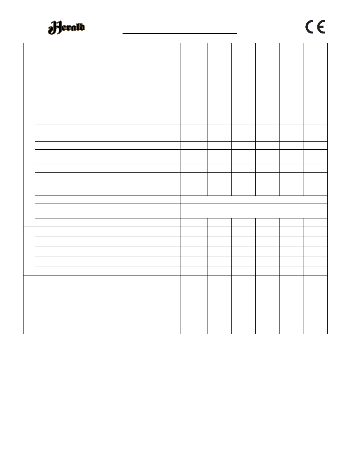
Technical Specification
GENERAL
MODELS :
Hawk 3 – CVHK03FM/CVHK03DFM/
CVHK03FWCVHK03DFW
Hawk 4 – CVHK04FM/CVHK04DFM/
CVHK04FWCVHK04DFW
Kestrel – CVSKS05FM
Herald 4 – CVHH04FMN/CVSHH04FM/
CVHH04FWN/CVSHH04FW
Compact 5 – CVC05FM/CVSC05FM/
CVC05FW/CVSC05FW
Slimline 5 – CVHH05FMN/CVSHH05FM/
CVHH05FWN/CVSHH05FW
KESTREL
HAWK 3
HAWK 4
HERALD 4
COMPACT 5
5 SLIMLINE
Energy Efficiency Class
A A+ A A A A
Nominal Heat Output
Wood
4.8kW
4.2kW
4.7kW
4.0kW
4.7kW
4.4kW
Nominal Heat Output
Ancit
NA
NA
3.3kW
NA
NA
NA
Energy Efficiency
102
108
97
104
101
98
Efficiency
Wood
76.8%
80.5%
72.8%
78.0%
76.0%
74.1%
Efficiency
Ancit
NA
NA
66.7%
NA
NA
NA
Mean CO (@13% O₂)
Wood
0.43%
0.24%
0.27%
0.44%
0.30%
0.32%
Mean CO (@13% O₂)
Ancit
NA
NA
0.54%
NA
NA
NA
Appliance Mass
75kg
62kg
71kg
90kg
99kg
90kg
Recommended Fuels
Wood
Seasoned Wood (less than 20% moisture content)
Smokeless
Fuel
Anthracite or a manufactured briquette smokeless fuel
which is suitable for closed door appliances.
Log Length (mm)
258
258
280
280
330
400
FLUES
Mean Flue Gas Temperature
Wood
271°C
227˚C
270˚C
246˚C
269˚C
268˚C
Mean Flue Gas Temperature
Ancit
NA
NA
332˚C
NA
NA
NA
Flue Gas Mass Flow
Wood
4.3 g/s
5.6 g/s
5.7 g/s
3.8 g/s
4.7 g/s
5.0 g/s
Flue Gas Mass Flow
Ancit
NA
NA
7.9 g/s
NA
NA
NA
Flue Outlet Size (Top or Rear Option) (mm)
125
125
125
125
125
125
VENTILATION
- Where leakage is greater than 5m³/hour/m²
- Ventilation normally required = 550mm² per
kW output over 5kW
NONE
NONE
NONE
NONE
NONE
NONE
- Where leakage is less than or equal to
5m³/hour/m²
- Ventilation normally required = 550mm² per
kW output
2640
mm²
2255
mm²
2585
mm²
2200
mm²
2585
mm²
2420
mm²
For further information on ventilation please refer to Building Regulations Document J or your installer.
This stove has been designed and assembled so that it may be used to burn wood logs in a Smoke Control Area.
Find out if you are in a Smoke Control Area by contacting your Local Authority.
The Kestrel, Hawk 4, Herald 4, Compact 5, 5 Slimline have been fitted with a permanent stop that prevents closure of
the secondary air slider. Removal of this will lead to the appliance potentially causing smoke emissions. Without the
permanent stop in place the appliance is not an exempt appliance and so may leave the householder liable for a fine
up to £1000.
Page 4
4
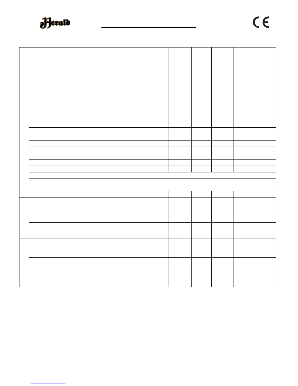
Technical Specification
GENERAL
MODELS :
Hawk 3 – CVHK03FM/CVHK03DFM/
CVHK03FWCVHK03DFW
Hawk 4 – CVHK04FM/CVHK04DFM/
CVHK04FWCVHK04DFW
Kestrel – CVSKS05FM
Herald 4 – CVHH04FMN/CVSHH04FM/
CVHH04FWN/CVSHH04FW
Compact 5 – CVC05FM/CVSC05FM/
CVC05FW/CVSC05FW
Slimline 5 – CVHH05FMN/CVSHH05FM/
CVHH05FWN/CVSHH05FW
HERALD 6
HERALD 8 SLIMLINE
LOW OUTPUT
INGLENOOK
HIGH OUTPUT
INGLENOOK
HERALD 8
HERALD 14
Energy Efficiency Class
A A
A+ A A A Nominal Heat Output
Wood
5.4kW
5.0kW
7.3kW
10.2kW
9.1kW
11.9 kW
Nominal Heat Output
Ancit
6.5kW
NA
6.0kW
NA
7.8kW
9.0 kW
Energy Efficiency
101
96
112
105
105
105
Efficiency
Wood
75.9%
72.4%
83.6%
78.4%
78.9%
78.6%
Efficiency
Ancit
67.3%
NA
68.4%
NA
68.5%
79.4%
Mean CO (@13% O₂)
Wood
0.27%
0.25%
0.30%
0.40%
0.38%
0.57%
Mean CO (@13% O₂)
Ancit
0.22%
NA
0.21%
NA
0.35%
0.18%
Appliance Mass
101kg
115kg
148kg
160kg
120kg
145kg
Recommended Fuels
Wood
Seasoned Wood (less than 20% moisture content)
Smokeless
Fuel
Anthracite or a manufactured briquette smokeless fuel
which is suitable for closed door appliances.
Log Length (mm)
380
500
480
500
500
500
FLUES
Mean Flue Gas Temperature
Wood
265°C
271˚C
214˚C
291˚C
293˚C
339˚C
Mean Flue Gas Temperature
Ancit
332˚C
NA
235˚C
NA
304˚C
275˚C
Flue Gas Mass Flow
Wood
5.7 g/s
6.2 g/s
5.5 g/s
7.3 g/s
6.4 g/s
6.4 g/s
Flue Gas Mass Flow
Ancit
7.9 g/s
NA
6.8 g/s
NA
7.2 g/s
7.2 g/s
Flue Outlet Size (Top or Rear Option) (mm)
150
125
150
150
150
150
VENTILATION
- Where leakage is greater than 5m³/hour/m²
- Ventilation normally required = 550mm² per
kW output over 5kW
220m
m²
NONE
1265
mm²
2860
mm²
2255
mm²
3795
mm²
- Where leakage is less than or equal to
5m³/hour/m²
- Ventilation normally required = 550mm² per
kW output
2970
mm²
2750
mm²
4015
mm²
5610
mm²
5005
mm²
6545
mm²
For further information on ventilation please refer to Building Regulations Document J or your installer.
This stove has been designed and assembled so that it may be used to burn wood logs in a Smoke Control Area.
Find out if you are in a Smoke Control Area by contacting your Local Authority.
The 8 Slimline only has been fitted with a permanent stop that prevents closure of the secondary air slider. Removal
of this will lead to the appliance potentially causing smoke emissions. Without the permanent stop in place the
appliance is not an exempt appliance and so may leave the householder liable for a fine up to £1000.
Page 5
5
General Guidance
It is important that your stove is correctly installed
and operated as Hunter Stoves Group cannot accept
responsibility for any fault arising through incorrect
installation, use, maintenance or servicing.
These instructions cover the basic principles to
ensure satisfactory installation of the stove, although
detail may need slight modification to suit particular
local site conditions.
The installation must comply with current Building
Regulations, National and European Standards, Local
Authority Byelaws and other specifications or
regulations as they affect the installation of the
appliance.
The Building Regulations requirements may also be
met by adopting the relevant recommendations in
the current issues of British Standards BS 8303 and
BS EN 15287-1.
Only use approved fuels on this appliance.
Information about this can be found on Page 17.
This is a Domestic Appliance and must only be used in
accordance with these instructions. Do not place
articles that are affected by high temperatures on, or
near, this appliance. Do not place furniture or other
items within 1 metre of the front of this appliance.
See the note on material clearances on pages 12/13.
Fitting a stove in a room which also contains an
extractor fan and/or cooker hood should be avoided
where possible. If this is unavoidable, the suitability
of the space for fitting this appliance must be decided
at the discretion of a qualified installer, and a flue
draught interference test must be performed.
Do not obstruct the ventilation required for the safe
use of this appliance.
COMPETENT PERSONS SCHEME
Hunter Stoves Group recommend that this stove is
installed by a member of an accredited competent
persons scheme e.g. HETAS.
If the installer is not a member of a competent
person’s scheme, it is a legal requirement, in the UK,
to notify your Local Building Control Officer in
advance of any installation work starting.
HEALTH AND SAFETY PRECAUTIONS
Special care must be taken when installing the stove
such that the requirements of the Health and Safety
at Work Act are met.
HANDLING
This appliance is very heavy. Adequate facilities must
be available for loading, unloading and site handling.
FIRE CEMENT
Some types of fire cement are caustic and should not
be allowed to come into contact with the skin. In case
of contact, wash immediately with plenty of water.
ASBESTOS
This stove contains no asbestos. If there is a possibility
of disturbing any asbestos in the course of
installation, then please seek specialist guidance and
use appropriate protective equipment.
METAL PARTS
When installing or servicing this stove, care should be
taken to avoid the possibility of personal injury.
MODIFICATION
No unauthorised modification of this appliance should
be carried out.
SAFETY
WARNING – This appliance will be hot when in
operation and due care should be taken. The supplied
operating tool or glove may be used to open the door
and operate the air controls.
PLEASE READ THESE INSTRUCTIONS PRIOR TO INSTALLATION AND OPERATION. KEEP THESE
INSTRUCTIONS IN A SAFE PLACE FOR FUTURE REFERENCE AND SERVICING.
THIS APPLIANCE WILL BECOME VERY HOT WHEN USED IN ACCORDANCE WITH THESE INSTRUCTIONS,
HUNTER STOVES RECOMMEND THAT AN APPROVED GUARD IS USED TO PROTECT THE YOUNG, ELDERLY
OR INFIRM FROM HARM.
THE INSTALLER COMMISSIONING SHEET CAN BE FOUND ON THE BACK COVER. PLEASE ENSURE THAT IT IS
COMPLETED PRIOR TO USE.
Page 6
6
AEROSOLS
Do not use an aerosol spray on or near the stove
when it is alight.
FIREGUARDS
Always use a fireguard in the presence of children, the
elderly or the infirm. The fireguard should be
manufactured in accordance with BS8423 – Fireguards
for use with solid fuel appliances.
DO NOT OVER-FIRE
It is possible to fire the stove beyond its design
capacity. This could damage the stove so watch for
signs of over-firing. If any part of the stove starts to
glow red, the stove is in an over-fire situation and the
controls should be adjusted accordingly.
Never leave the stove unattended for long periods
without first adjusting the controls to a safe setting.
Careful air supply control should be exercised at all
times.
FUME EMISSION
Properly installed, operated, this appliance will not
emit fumes. Occasional fumes from de-ashing and
refuelling may occur. Persistent fume emission must
not be tolerated.
This appliance should not be operated with the door
open.
If fume emission persists, then the following
immediate action should be taken: -
➢ Open doors and windows to ventilate the room.
➢ Let the fire go out, or eject and safely dispose of
fuel from the appliance.
➢ Check for flue/chimney blockage and clean if
required.
➢ Do not attempt to re-light the fire until the cause
of the fume emission has been identified and
corrected.
If necessary, seek expert advice.
ADVERSE WEATHER
In a small number of installations, occasional local
weather conditions (e.g. wind from a particular
direction) may cause downdraught in the flue and
cause the stove to emit fumes. In these
circumstances, the stove should not be used. A
professional flue installer will be able to advice on
solutions to this problem (e.g. anti-downdraught
cowl).
CARBON MONOXIDE DETECTOR
Hunter Stoves recommend a Carbon Monoxide
Detector that conforms to the latest issue of BS EN
50292 is placed in the same room as the appliance.
The installation of such an alarm is not considered as
a substitute for regular maintenance or servicing or
the appliance and Flue system.
IN THE EVENT OF A CHIMNEY FIRE:
➢ Raise the alarm
➢ Call the Fire Brigade
➢ Close appliance air controls
➢ Move furniture, ornaments etc. away
➢ Place a fireguard in front of stove
➢ Check the chimney breast for signs of
excessive heat.
If the wall is becoming excessively hot, move furniture
away. Ensure the Fire Brigade can gain access to your
roof space in order to check for fire spread.
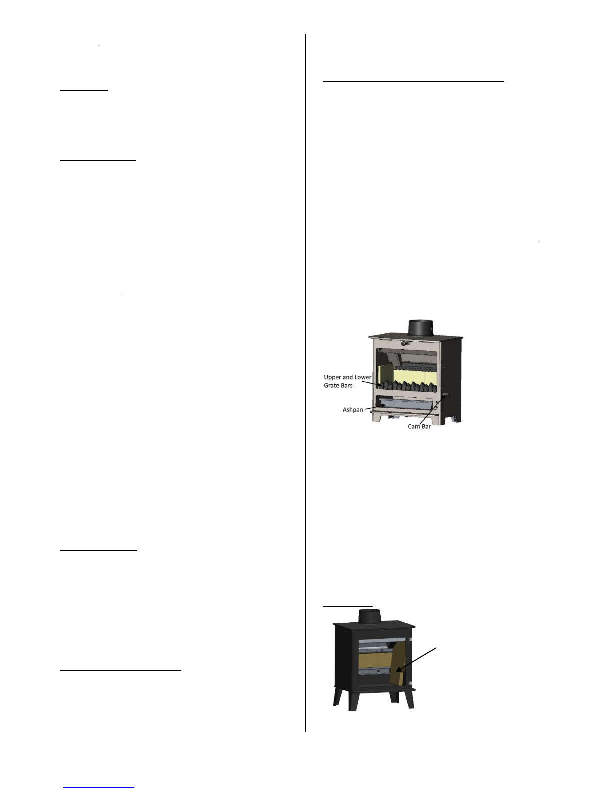
REMOVING INTERNAL COMPONENTS
All internal components must be removed prior to
fitting the stove. This will make handling the stove
easier; allow access to fixings and the flue outlet; as
well as protect the internal components from damage
during the installation process.
1. Open the door and remove the ashpan.
2. Remove the grate bars by lifting the front up
off the cam bar and sliding forward off the
rear grate support and lift out of the firebox.
3. Remove the cam bar by lifting the left-hand
end of it upwards until it clears the side
casting. Pull the left-hand end towards the
front of the stove and then slide all the way
out. Take care not to lose the cam hole plate.
4. Remove the catch bar by lifting upwards and
pulling forwards out of the stove body.
5. Remove both Side Plates by sliding out.
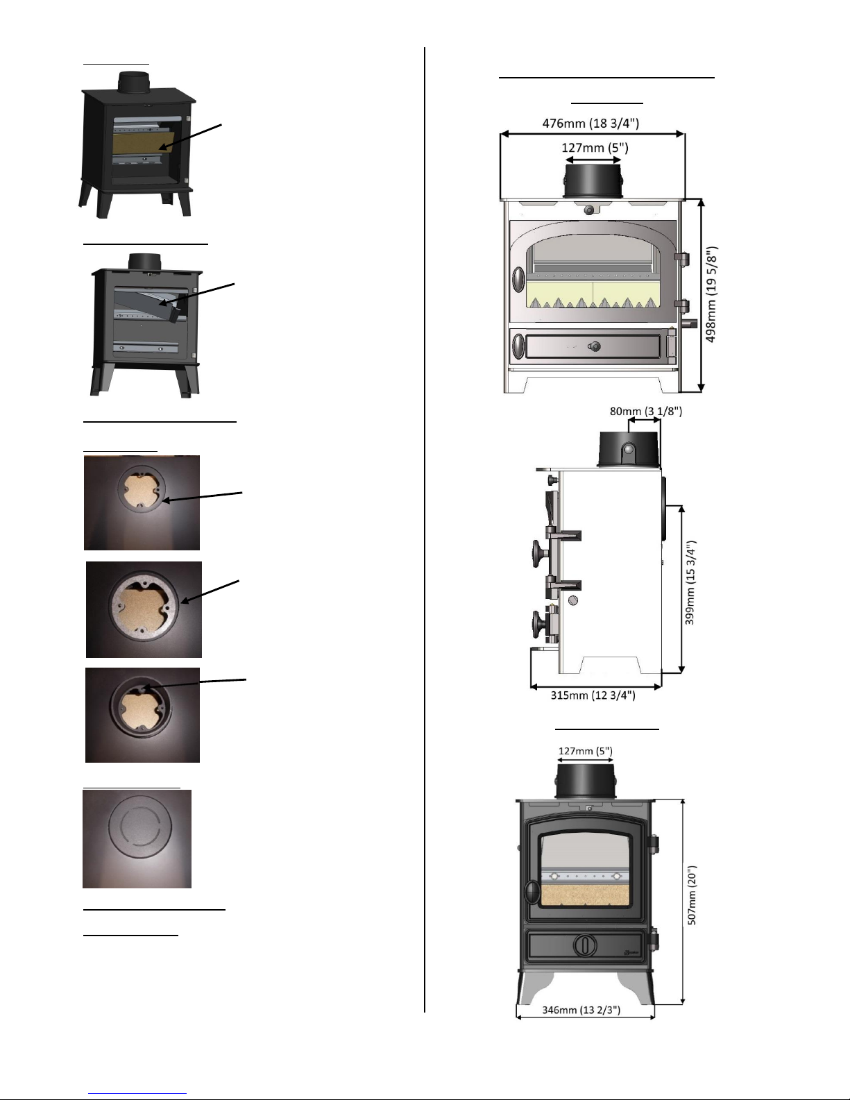
Side Bricks
Slide the base of the
Side Brick towards the
centre of the stove and
remove.
Page 7
7
Rear Brick
Baffle/Throat Plate
STOVE ASSEMBLY
Flue Collar
Blanking Plate
RE-ASSEMBLING
THE STOVE
Refit all the internal parts by following
the ‘removing internal component’
instructions in reverse order.
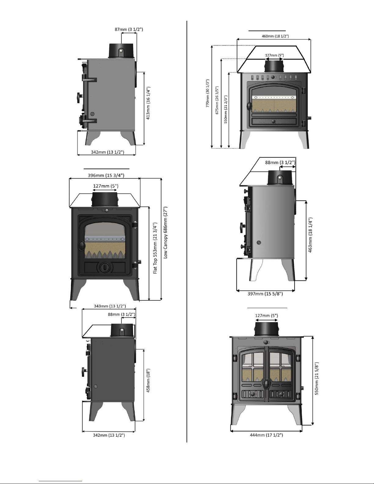
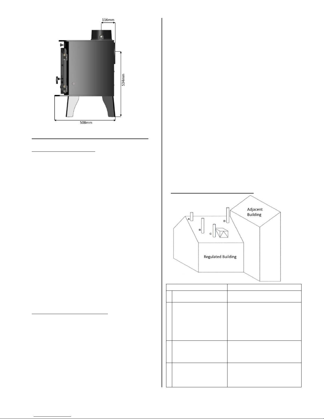
APPLIANCE DIMENSIONS
KESTREL
HAWK 3/3D
Pull the top edge of the
Rear Brick forward and lift
the brick out of the Stove.
Lift the Baffle and slide to
the right. When the left
side of the Baffle clears the
Baffle Support, lower the
Baffle into the Fire Box and
remove.
Place the bolts
downwards through the
fixing holes (head side
upwards). Then tighten
by using supplied nuts
from inside stove.
Place the gasket on the
outlet and put blanking
plate on top of this.
Screw the bolts from the
inside of the stove into
the blanking plate.
Place the flue collar
gaskets on the outlet to
be used.
Top or rear outlet
Page 8
8
HAWK 4/4D
HERALD 4
HAWK 4/4D
COMPACT 5
COMPACT 5
Page 9
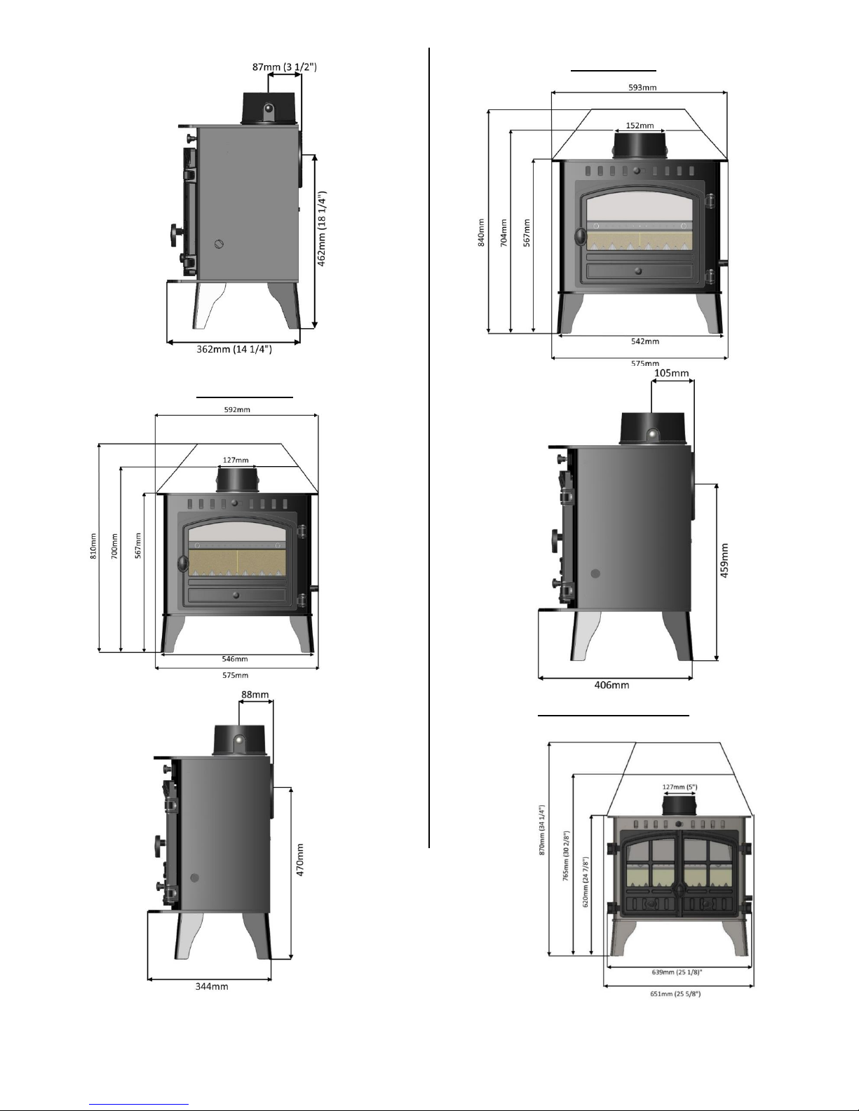
9
5 SLIMLINE
HERALD 6
HERALD 8 SLIMLINE
Page 10

10
LOW/HIGH OUTPUT INGLENOOK
HERALD 8
HERALD 14
Page 11
11
PRE-INSTALLATION REQUIREMENTS
PLEASE CHECK THE FOLLOWING:
Any existing chimney/flue system must be confirmed
as suitable for this appliance as defined in Building
Regulations Document J. It must be swept and
inspected, by a competent person (see notes), to
confirm that is structurally sound and free from cracks
and obstructions.
The diameter of the Flue should not be less than
Ø125mm (Kestrel, Hawk 3 & 4, Herald 4, 5C, 5S, 8S) or
152mm (Herald 6, Low/High Output Inglenook, 8/14)
and not more than Ø200mm or Ø230mm. Do not
connect to systems that have large voids or spaces. If
any of these requirements are not met, the chimney
should be lined by a suitable method.
If the chimney is suspected of previously serving an
open fire it must be swept again, within a month of
regular use, to clear any soot that may have been
dislodged due to the variation in combustion levels
and higher flue gas temperature levels. The
chimney/flue system exit must comply with Building
Regulations Document J. The minimum height and
should terminate in accordance with Table 1.
CONNECTION TO THE CHIMNEY
An existing fireplace opening can be bricked up or
sealed with a register plate. A short length of flue pipe
of minimum 125mm (Kestrel, Hawk 3 & 4, Herald 4,
5C, 5S, 8S) or 152mm (Herald 6, Low/High Output
Inglenook, 8/14) internal diameter may then be used
to connect the stove to the chimney. This flue pipe
should be made of 316 grade stainless steel or
vitreous enamelled steel, nominal thickness 1.2mm.
Ensure that the pipe end is no closer than 76mm to
the chimney walls. The length of any horizontal run of
flue pipe must not exceed 125mm or 152mm (as
above). It is essential that all connections between the
stove and chimney-flue are sealed and made airtight.
Make provision to access the chimney/flue system for
cleaning and the removal of debris. If there is no
existing chimney then either a prefabricated block
chimney in accordance with Building Regulations
Approved Document J, or a twin-walled insulated
stainless-steel flue to BS4543 can be used. These
chimneys must be fitted in accordance with the
manufacturer’s instructions and Building Regulations.
New masonry and flue block chimneys must meet the
requirements of Building Regulations Document J. Any
connecting flue pipe systems must also meet these
regulations.
Please check the suitability of the fireplace and/or
surround for use with this appliance before installing
it. If you have any doubts about the suitability of your
chimney, consult your local Dealer/Stockist or
Installation Engineer. Both the chimney and flue pipe
must be accessible for cleaning and if ANY part of the
chimney cannot be reached through the stove (with
baffle removed), a soot door must be fitted in a
suitable position.
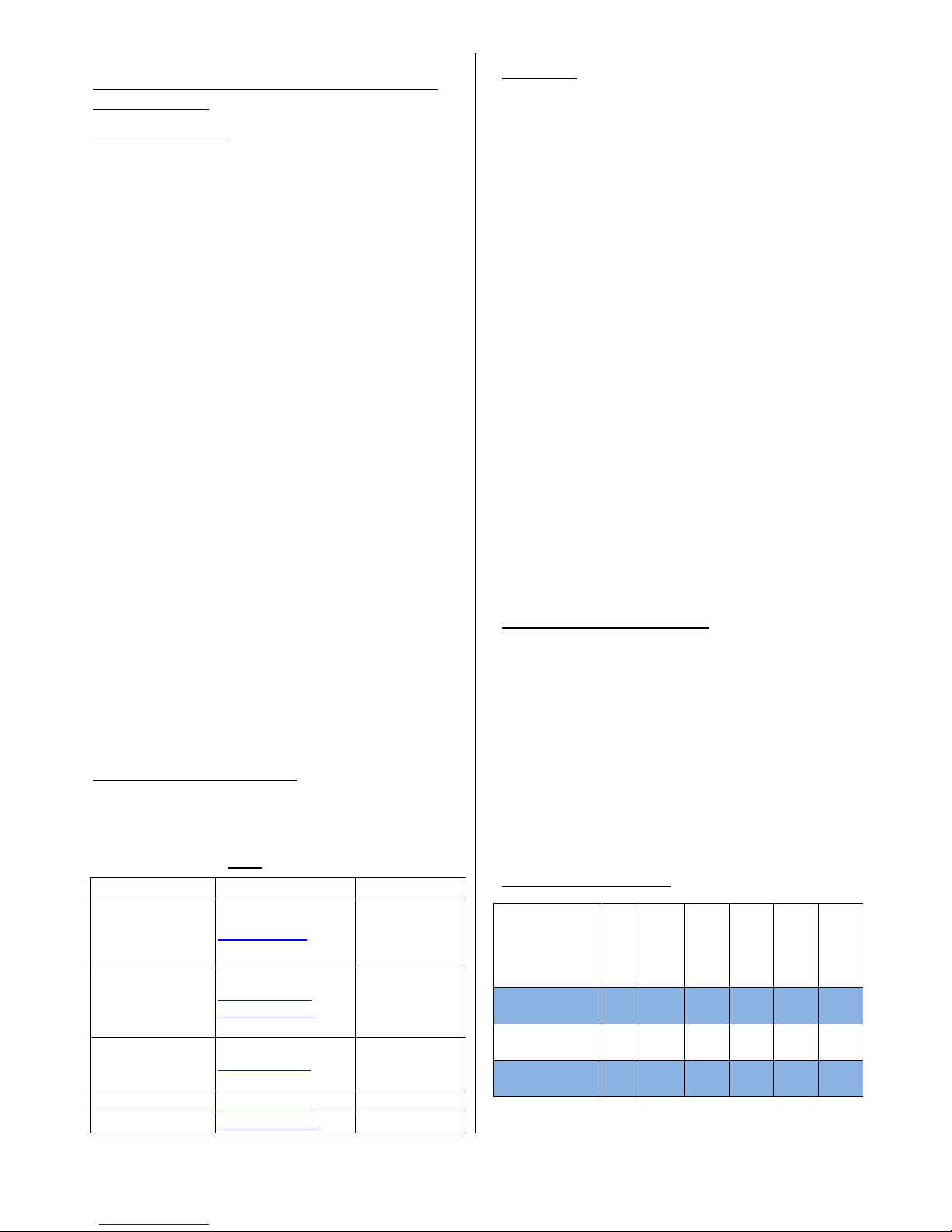
FLUE OUTLET POSITIONS (DOCUMENT J):
Position on Roof
Clearances to flue exit
A At or within
600mm of the ridge
At least 600mm
above the ridge
B Elsewhere on a roof
(Pitched or Flat)
At least 2.3 M horizontally
from the nearest point on the
weather surface and:
a) At least 1.0 M above the highest
point of intersection between the
chimney and weather surface; or
b) at least as high as the ridge
C Below (on a pitched roof)
or within 2.3 M
horizontally to an opening
window or dormer.
At least 1.0 M above the top of the
opening
D Within 2.3 M of an
adjoining or adjacent
building, whether or not
beyond the boundary
At least 600mm above any part of
the adjacent building within 2.3 M
Page 12
12
A full copy of Document J can be found here:
http://www.planningportal.gov.uk/uploads/br/BR_P
DF_ADJ_2010.pdf
LEGAL REQUIREMENTS
Hunter Stoves Group requests that before installation
and/or use of this appliance that you read these
instructions carefully to ensure that all the relevant
requirements are fully understood.
These instructions cover the basic principles to ensure
satisfactory installation of the stove, although detail
may need slight modification to suit particular local
site conditions. In all cases the installation must
comply with current Building Regulations, Local
Authority Byelaws, European and National Standards
and other specifications or regulations as they affect
the installation of the stove.
It should be noted that the Building Regulations
requirements may be met by adopting the relevant
recommendations given in British Standards BS 8303,
BS 6461 and BS 7566 as an alternative means to
achieve an equivalent level of performance to that
obtained following the guidance given in Approved
Document J.
Your local Building Control Officer can advise you
regarding the interpretation of the Regulations should
there be any questions.
This appliance must be installed by a Registered
Installer (see Competent Persons Scheme) or
approved by your local Building Control Officer.
All works undertaken must be carried out with due
care and attention to meet the requirements of the
Health & Safety code of practice and any other
legislation that may have been introduced since the
publication of these instructions.
Competent Persons Scheme
Members of the following schemes may self-certify
the installation of this stove. If the installer is not a
member of one of these schemes, your local Building
Control Department must approve the installation.
Scheme
Web address
Telephone
APHC (Association of
Plumbing and Heating
Contractors
(Certification) Limited
www.aphc.co.uk
02476 470 626
Building Engineering
Services Competence
Accreditation (BESCA
Limited)
www.hvca.org.uk /
www.besca.org.uk
0800 652 5533
HETAS Ltd (Heating
Equipment Testing
and Approval Scheme)
www.hetas.co.uk
01462 634721
NAPIT Registration Ltd
www.napit.org.uk
0870 444 1392
NICEIC Group Ltd
www.niceic.org.uk
0800 013 0900
Air Supply
The room or space containing this appliance does not
need a permanent, unobstructed air opening (Kestrel,
Hawk 3 & 4, Herald 4/5C/5S/8S. These stoves listed
below require a permanent, unobstructed air
opening:
Herald 6 – 220mm²
Low Output Inglenook – 1265mm²
High Output Inglenook – 2860mm²
Herald 8 – 2250mm²
Herald 14 – 3795mm²
If a draught stabiliser is fitted, the air opening should
be at least Kestrel - 1440mm².
Hawk 3 & 4,
Herald 4, 5C, 5S – 1230mm²
Herald 6 – 1275mm²
Herald 8 Slimline – 1500mm²
Low Output Inglenook – 4015mm²
High Output Inglenook – 5610mm²
Herald 8 – 4985mm²
Herald 14 – 5865mm²
Due consideration should be given to air requirements
for any other appliance in the same room or space.
Any air opening must be kept clear from blockage or
obstruction.
Hearth/ Material Clearances
Hearth constructions must comply with the current
building regulations.
Your stove must be installed on a floor with adequate
load-bearing capacity, otherwise suitable measures
should be taken.
If the existing construction does not meet this prerequisite, suitable measures (e.g. load distributing
plate).
Care should be taken to level the stove using the
adjusting screws in the feet.
Material Clearances
Minimum
Distances to
Combustible
Material
Kestrel
Hawk 3
Hawk 4
Herald 4
Compact 5
5 Slimline
Behind the
stove (mm)
750
400
650
650
750
650
At the side of
the stove (mm)
400
350
400
400
350
400
In front of the
stove (mm)
900
900
900
900
900
900
Page 13

13
Minimum
Distances to
Combustible
Material
Herald 6
8 Slimline
Low
Output
High
Output
Herald 8
Herald 14
Behind the
stove (mm)
650
750
600
1000
1100
1100
At the side of
the stove (mm)
400
450
300
400
700
650
In front of the
stove (mm)
900
900
900
900
900
900
Note: combustible material refers to any material that
will degrade when subjected to heat e.g. plaster.
No combustible material must be stored underneath
the stove.
FIREPLACE RECESS
The stove can be recessed in a suitable sized fireplace
but a permanent free air gap of at least 150mm on
top and 50mm at the sides (although we recommend
150mm for the sides and 50mm at the back of the
stove to obtain maximum heat output and for access
to the rear of the stove.)
The hearth should extend at least 300 mm from the
front of the stove. The stove should stand wholly
above a solid, non-combustible hearth, at least 125
mm thick (this may include the thickness of a solid
floor and a non-combustible decorative hearth).
FREE STANDING
KESTREL/HAWK 3 & 4/HERALD 4/COMPACT 5/
5 SLIMLINE/HERALD 6/LOW OUTPUT
INGLENOOK ONLY
If the stove is not to stand in a recess, it may stand
wholly above a hearth made of non-combustible
board / sheet material or tiles, at least 10mm thick.
The hearth should extend at least 150 mm from the
sides and rear of the stove, and at least 300 mm from
the front of the stove.
All walls shown in the above diagrams are noncombustible unless otherwise indicated. All noncombustible walls closer than 300mm to the stove
should be at least 75mm thick.
COMMISSIONING & HANDOVER
APPLIANCE CHECK
Please check that all components are correctly
assembled and working correctly.
Ensure the Air Controls are working correctly.
Hunter Stoves Group recommend that you carry out a
smoke draw test to check the soundness of the
chimney/flue system and seals:
Place a Smoke Pellet in the centre of the Grate,
ensure that all of the Air Controls are fully open and
close the Door.
Page 14

14
The smoke should now be drawn up the chimney and
you should be able to see it exit from the
chimney/flue terminal.
We recommend that you do this test with all of the
windows and doors, to the room where the appliance
is fitted, closed.
If there any adjoining room(s) that have an Extractor
Fan fitted, open the adjoining door to ensure that the
chimney/flue system is not compromised when the
fan is operating. If there is a ceiling fan fitted in the
room please operate it and ensure that it does not
affect the operation of the chimney/flue system.
If any of these tests fail, please re-check the
suitability of the chimney/flue system together with
the ventilation.
A small fire can now be lit and allow the appliance to
heat up slowly ensuring that no products of
combustion enter into the room.
Carry out a spillage test using a smoke match around
the door opening.
If there is excessive spillage please allow the appliance
to cool and then re-check the chimney/flue system
and ventilation.
Do not run the stove at full output for at least 24
hours.
On completion of the commissioning:
Upon completion, allow a suitable period of time for
any fire cement and mortar to dry out.
Please instruct the user on the safe operation of this
appliance, how the controls work and basic
maintenance requirements.
Ensure that the operating instructions and appliance
tools are left with the customer and the check lists
have been filled out correctly.
Please advise the customer on the correct use of the
appliance with the fuels likely to be used on the stove
and warn them to use only the recommended fuels
for the stove.
Advise the user on what to do should smoke or fumes
be emitted from the stove.
The user should be warned to use a fireguard to BS
8423 in the presence of children, aged and/or infirm
persons.
Hunter Stoves Group also recommend that a CO alarm
is fitted into the room where the appliance is located.
FLUE DRAUGHT
If the draught exceeds the recommended maximum, a
draught stabiliser must be fitted so that the rate of
burning can be controlled and to prevent over firing.
If the reading is less than the recommended
minimum then the performance of the appliance will
be compromised. The flue draught should be checked
under fire at high output with windows and doors
closed. To take the reading remove one of the coach
bolts in the flue collar and put the probe in the hole.
Minimum Draught – 1.2mm Water Gauge
Maximum Draught – 2.5mm Water Gauge
THE CLEAN AIR ACT 1993 AND SMOKE CONTROL AREAS
KESTREL/HAWK 4/HERALD 4/COMPACT 5/
5 SLIMLINE/HERALD 6/8 SLIMLINE
Under the Clean Air Act local authorities may declare the
whole or part of the district of the authority to be a smoke
control area. It is an offence to emit smoke from a chimney
of a building, from a furnace or from any fixed boiler if
located in a designated smoke control area. It is also an
offence to acquire an "unauthorised fuel" for use within a
smoke control area unless it is used in an "exempt"
appliance ("exempted" from the controls which generally
apply in the smoke control area).
In England appliances are exempted by publication on a list
by the Secretary of State in accordance with changes made
to sections 20 and 21 of the Clean Air Act 1993 by section
15 of the Deregulation Act 2015. Similarly, in Scotland
appliances are exempted by publication on a list by Scottish
Ministers under section 50 of the Regulatory Reform
(Scotland) Act 2014.
In Wales and Northern Ireland these are authorised by
regulations made by Welsh Ministers and by the
Department of the Environment respectively.
Further information on the requirements of the Clean Air
Act can be found here:
https://www.gov.uk/smoke-control-area-rules
The wood burning stoves listed above have been
recommended as suitable for use in smoke control
areas. Suitable Authorised fuels can also be used in the
appliances in Smoke Control Areas (see Authorised fuel list
https://smokecontrol.defra.gov.uk/fuels.php )
Refuelling on to a low fire bed
If there is insufficient burning material in the fire bed to
light a new fuel charge, excessive smoke emission can
occur. Refuelling must be carried out onto a sufficient
quantity of glowing embers and ash that the new fuel
charge will ignite in a reasonable period. If there are too
few embers in the fire bed, add suitable kindling to prevent
excessive smoke.
Fuel overloading
The maximum amount of fuel specified in this manual
should not be exceeded, overloading can cause excess
smoke.
Page 15

15
Operation with door left open
Operation with the door open can cause excess smoke. The
appliance must not be operated with the appliance door
left open except as directed in the instructions.
Dampers left open
Operation with the air controls or appliance dampers open
can cause excess smoke. The appliance must not be
operated with air controls, appliance dampers or door left
open except as directed in the instructions.
Operating Instructions
Read the ‘General Guidance’ Section at the start of
these instructions before operating your stove for the
first time.
Allow sufficient clearance between the stove and
pictures, plasma screen televisions or ornaments etc.,
as these could be damaged and could potentially
create a fire hazard (For more information read the
‘Material Clearance’ section of these installation
instructions).
WARNING – This appliance will be hot when in
operation and due care should be taken. The
supplied operating tool or gloves may be used to
open the door and operate the air controls.
PLEASE NOTE
Your Building Insurance Company may require you to
inform them of this new installation and that the work
has been carried out correctly. Please check your
policy to ensure that it is still valid when this
installation is complete.
USING THE APPLIANCE FOR THE FIRST TIME
We recommend that the appliance is left for 24 hours
after installation to allow the fire cement, fixing glues,
etc. to cure.
With the painted finish, we recommend that you have
two or three small fires before you operate your stove
to its maximum heat output. This is to allow the paint
to cure in steadily and to give a long service life of the
paint finish.
During this curing in process you may notice an
unpleasant smell. It is non-toxic, but for your comfort
we would suggest that during this period you leave all
doors and windows open.
AEROSOLS
Do not use an aerosol spray on or near the stove
when it is alight.
AIR CONTROL
This stove has been designed to burn far more
efficiently than a traditional stove if used correctly,
with the obvious notable feature of CLEAN GLASS.
It is essential that the stove has an adequate air
supply for combustion and ventilation.
The primary and secondary air inlets must be kept
clear from obstruction and blockage.
Primary Air
This provides a conventional air draught to the bed of
the fire.
Primary air is controlled
via the slider in the ash pit
door (Kestrel only) or in the
case of the others slider in
the door(s).
Secondary Air
Secondary air is controlled via
the slider above the door(s);
it is this “Air wash” that keeps
a clean and uninterrupted view
of the fire. The amount of air
can be increased by moving the
slider to the right.
Tertiary Air/Data Plate
Tertiary air aids in good secondary combustion of the
fuel and reducing emissions into the chimney and
environment.
Tertiary air can be controlled by
adjusting the cover plate on the
back of the stove.
Data plate
Warning! – This Appliance will be hot when in
operation and due care should be taken.
We advise that suitable gloves are used when
operating the air control, and when opening the door.
Lighting the Stove
To light the stove, open the primary and secondary air
controls fully.
Light one or two firelighters placed centrally on the
grate, allowing the flames to become established
before placing several pieces of small dry kindling in a
criss-cross fashion above the firelighters, taking care
not to smother the fire.
Close the stove door. Once the kindling is well alight
open the door and build the fire by gradually adding
slightly larger pieces of wood, closing the door
afterwards.
Page 16

16
Once you have a good fire established across the
grate bed, further fuel can be added as required and
the air controls set to the correct position.
Should the fire fail to light correctly open the door
and use a poker to spread the fuel across the grate.
Close the door and allow the fuel and stove to cool
before attempting to relight the fire.
N.B. Leaving the air controls in the closed position,
adding too much fuel or using wood that is wet or too
large will prevent the fire from establishing correctly
and may result in smoke emission from the stove.
LOCOMOTIVE GRATE
GRATE OPERATION & BURNING WOOD
Your stove is fitted with a locomotive type grate. So
that de-ashing can be carried out cleanly and easily, it
is riddled from the outside of the stove with the doors
closed.
To burn wood, push the operating tool up and away
from you.
When left in this position, air is restricted through the
bed of the fire providing a solid base to build up a bed
of ash.
Surplus ash can be removed either
by gentle riddling or with a shovel.
It might prove beneficial when
burning more reactive fuels to
leave the grate in a “neutral”
position, thus directing some
under fire air and some over fire
air to the fire bed.
GRATE OPERATION & BURNING SOLID MINERAL
FUELS
To burn solid mineral fuels, place the operating
tool over the riddling spigot and pull it towards you.
When left in that position, air is directed under and up
through the slots in the fire bed, giving the optimum
conditions for burning solid fuels.
It is important that the riddling tool is used to remove
the ash to ensure airflow through the fire bed and
allow the fire to burn over the entire area of the
grate. The ashpan should be emptied at least daily
and ash should never be allowed to build up over a
period of time as this will result in damage to the fire
bars. The flat end of the riddling tool can be used to
carry the ashpan.
LOADING THE APPLIANCE (SOLID MINERAL FUEL)
Solid mineral fuel should be placed in the stove so
that there is no more than a 30° incline of the
fuel bed from front to back. It should not be stacked
above the level of the rear firebrick as this
may result in damage to the stove. With a full load of
fuel, the stove will need to be refuelled approximately
once every 2 hours.
AIR CONTROLS (SOLID MINERAL FUEL)
Solid mineral fuel burns most efficiently with the
secondary air control in the closed position.
The primary valve lever can then be used to control
the burn rate of the stove.
Always de-ash before refuelling and do not let the ash
build up to the underside of the grate bars.
Solid mineral fuel produces ash, which if allowed to
build up will stifle the airflow through the
Primary air valve cavity and grate. This will eventually
cause the fire to die.
With some solid mineral fuels, a residue of burnt fuel
or clinker will accumulate on the grate,
allow the fire to go out periodically to remove this.
IMPORTANT!
We cannot stress firmly enough how important it is to
empty the ashpan regularly. Air passing through the
fire bed cools the grate bars. Distortion or burning out
the grate bars is nearly always caused by ash being
allowed to build up to the underside of the grate.
EXTENDED BURNING (SOLID MINERAL FUEL)
The stove can be banked up for extended burning.
When burning solid fuel, empty the ashpan. Open air
controls and let the fire burn brightly for a short
period. Refuel and close both air controls, the exact
setting required will depend on the fuel used and the
chimney draw so some practice may be necessary.
To revive the fire, open the air controls until the fire is
burning brightly de-ash if necessary and refuel. Set air
controls as required.
Never leave the stove unattended until you are
certain that the flames are fully established.
Should the fire fail to light correctly open the door
and use a poker to spread the fuel across the bottom
of the firebox. Close the door and allow the fuel and
stove to cool before attempting to relight the fire.
Notes on Woodburning
With a full load of wood, the stove will need to be
refuelled approximately once every hour. Wood can
be stacked in the stove, but care must be taken that
logs do not touch the baffle. Overloading the stove
can cause excess smoke to be emitted. Wood burns
most efficiently with the secondary air valve lever in
the open position and the primary control closed.
Moving the secondary control will control the burn
rate of the stove.
Page 17

17
Note - primary and secondary air is needed to light
the stove, see section entitled ‘Lighting the Stove’
Wood burns most efficiently on a bed of ash and it is
therefore only necessary to remove surplus ash from
the stove occasionally.
If there is insufficient burning material in the fire bed
to light a new fuel charge, excessive smoke emission
can occur.
Refuelling must be carried out with a sufficient
quantity of glowing embers and ash, so that the new
fuel charge will ignite quickly. If there are too few
embers, add some kindling to prevent excessive
smoke.
Maximum Length:
See technical table
Ensure your logs are well seasoned with a moisture
content of less than 20%
REDUCED COMBUSTION
In order to shut down the stove, close the primary
control, then close the secondary air slider by moving
the handle all the way to the left.
If the controls are left in this position, the fire will be
starved of air and will die down.
If you want to revive the fire it is recommended that
the primary air control is open first, and then open
the secondary air slider. Warning! - The stove will
remain hot for a considerable time after the fire has
been extinguished.
REFUELLING
Refuelling must be carried out with a sufficient
quantity of glowing embers and ash, so that the new
fuel charge will ignite quickly. If there are too few
embers, add some kindling to prevent excessive fuel.
The air controls should not need adjusting while
refuelling.
(When refuelling it is important to have a damper in
the open position if you have one.)
Recommended Fuels
Hunter Stoves Group recommend that only wood logs
with a moisture content of less than 20% and
anthracite or a manufactured briquette smokeless
fuel which is suitable for closed door appliances are
used on this appliance. Burning wet or unseasoned
wood will create excess smoke emissions, tar deposits
in the stove and chimney and will not produce a
satisfactory heat output.
Only authorised fuels may be used in UK smoke
control areas. A list of authorised fuels can be found
at http://uksmokecontrolareas.co.uk/fuels.php
WARNING - DO NOT BURN BITUMINOUS COAL,
PETRO-COKE, OTHER PETROLEUM BASED FUELS OR
TREATED WOOD SUCH AS PALLETS AS THIS WILL
INVALIDATE THE PRODUCT WARRANTY. HOUSEHOLD
WASTE MUST NOT BE BURNT ON THIS APPLIANCE.
A list of approved fuels can be found at: -
HETAS Ltd – Telephone 01242 673257 –
http://hetas.co.uk/public/hetas_guide.html
Solid Fuel Association – Telephone 0800 600 000 –
www.solidfuel.co.uk
MAINTENANCE AND SERVICING
WARNING!
NO unauthorised modification of this appliance
should be carried out.
IMPORTANT!
In order to ensure continued compliance with current
Building Regulations and Local Authority Byelaws, this
appliance requires regular maintenance by a
competent person. N.B. Refer to the ‘Removing
Internal Components’ section of the installation
instructions for details on how to remove each
component.
PERIODS OF PROLONGED NON-USE
If the stove is to be left unused for a prolonged
period, then it should be given a thorough clean to
remove ash and unburned fuel residues. To enable a
good flow of air through the appliance to reduce
condensation and subsequent damage, leave the air
controls fully open. If the appliance has been unused
for a long period, such as during the spring and
summer months, a competent person should check
the chimney for potential obstructions before lighting
the stove i.e. get the chimney swept before the start
of the heating season?
BAFFLE
This should be removed and cleaned at least once a
month to prevent any build-up of soot or fly ash that
could lead to blocked flue ways and dangerous fume
emission. If the baffle is removed the chimney/flue
way can be swept through the appliance.
STOVE BODY
Painted Finish - The stove is finished with a heat
resistant paint and this can be cleaned with a dry soft
brush or dry microfiber cloth. Do not clean whilst the
stove is hot. At no point should any water or other
cleaning products be used on the stove. The finish
can be renovated with Hunter Stoves paint.
Page 18

18
GLASS PANEL
Clean the glass panel when cool with a propriety glass
cleaner. Highly abrasive substances should be
avoided as these can scratch the glass and make
subsequent cleaning more difficult. Wet logs on
heated glass, a badly aimed poker or heavy slamming
of the doors could crack the glass panels. The glass
will not fracture from heat. Should you need to
replace a glass panel please ensure you purchase a
new Gasket at the same time. Please check
periodically that the glass clips and screws have not
become loose. They should only be finger tight to
allow for the expansion and contraction of the glass.
GASKETS
All gasket used on this appliance are produced from a
heat resistant material called Manniglas.
The glass gasket will have to be replaced when a new
piece of glass is fitted as the gaskets become brittle
after firing the stove.
Over time you may also find that the gasket changes
colour. This is due to a reduction in the pigment used
in the manufacture of the product and no cause for
concern.
FIREBRICKS
In normal use, these can last for many years. It is
possible however, to crack them if logs are continually
jammed against them or if they are frequently struck
with a poker. Check periodically for seriously cracked
bricks, which can be replaced with new, available
from your dealer or our spares website
www.hunterstoves.co.uk.
DOOR CATCH
The door catch may require adjustment to maintain
the door seal. By slackening the internal locking nut
and turning the catch bolt one turn towards the door
you will achieve a tighter lock when the door is closed.
ROPE
Check the rope around the door. If rope is becoming
detached, use rope glue to reattach it. If the rope is in
a poor condition, a replacement rope kit may be
ordered from the Hunter Stoves Group spares range.
CHIMNEY AND FLUE WAYS
It is important that the chimney, flue ways and any
connecting flue pipe are swept regularly. This means
at least once a year for smokeless fuels and at least
twice a year for wood and other fuels. The baffle will
need to be removed from its supports in order to
sweep the chimney (see assembly instructions). Only
wire-centred sweeps’ brushes fitted with a guide
wheel should be used. If it is not possible to sweep all
parts of the chimney through the appliance, ensure
there is adequate access to cleaning doors. If the
stove is fitted in place of an open fire, then the
chimney should be swept one month after installation
to clear any soot falls which may have occurred due to
the difference in combustion between the stove and
the open fire.
ANNUAL SERVICE
Hunter Stoves Group recommend that this appliance
is serviced annually, preferably prior to the start of
the heating season, thus avoiding any delay in
receiving replacement components, should you need
them.
If you feel unable to undertake this task, Hunter
Stoves recommend that you contact the installation
engineer for advice.
Remove all the internal components:
Riddling Bars, Cam Bar, Catch Bar, Ashpan, Side Plates
and Baffle. Clean them with a soft brush and inspect
them for damage.
Sweep the chimney/flue system if necessary.
Clean down the internal surfaces of the appliance
using a scraper or wire brush.
Inspect these surfaces for damage/corrosion.
If corrosion or damage is found we advise that you
consult with your installer about rectification/repair.
Brush out or vacuum the inside of the appliance and
re-fit the internal components.
Inspect the Glass and Gasket. Clean the Glass with a
non-abrasive cleaner if required. If the Gasket is torn
or damaged we recommend that is replaced to ensure
that no products of combustion enters the room
when the appliance is used.
Painted Finish – Use either a dry microfibre cloth or a
dry soft brush to clean the outer surface and touch up
the paint if necessary.
Burn the appliance at a low rate, after maintenance,
to allow any new seals, paint or glue cure properly.
The appliance may emit unpleasant odours during this
process, please ensure the room is well ventilated.
The paint can be ordered through our website
www.hunterstoves.co.uk.
Page 19

19
TROUBLESHOOTING
ISSUE
CAUSE
RESOLUTION
OPERATION
Problem starting the fire and
keeping it burning
Low flue draught
Speak to your installer
Wood with moisture content over 20%
Ensure use of dry seasoned wood
with less than 20% moisture content
Unable to control fire
High flue draught
Speak to your installer
Short burn time
Wood with moisture content over 20%.
Insufficient amount of fuel – refer to page 15
(Notes on Woodburning)
Ensure use of dry seasoned wood
with less than 20% moisture content
Over firing
High flue draught
Speak to your installer
Air controls left fully open
Close air control to reduce output
Low heat output
Low flue draught
Speak to your installer with advice on
a suitable flue system.
Wet wood (over 20% moisture content)
Ensure use of dry seasoned wood
with less than 20% moisture content
Excessive fuel consumption
High flue draught
Speak to your installer
Over dry wood
Do not use constructional timber of
pallet wood
SMOKE PROBLEMS
Smoke and small flames
Wood with moisture content over 20%
Ensure use of dry seasoned wood
with less than 20% moisture content
Excessive smoke into room
when appliance door is opened
Low flue draught
Speak to your installer
Incorrect additional ventilation air in to the
building
Speak to your installer
Continuous smoke spillage into
the room when stove is in use
Blocked flue
Open all doors and windows to
ventilate the room. Allow the fire to
go out. Check flue for blockage. Do
not re-use until the problem has been
identified. If in doubt speak to your
installer.
ADVERSE
WEATHER
Windy days causing spillage into
the room
Down draught in flue caused by air
turbulence due to nearby buildings or trees.
Weather conditions combined with
the flue terminal position can have an
effect on the stoves performance.
Speak to your installer.
Calm days causing spillage into
the room
Over size flue giving poor flue draught
Weather conditions combined with
the flue terminal position can have an
effect on the stoves performance.
Speak to your installer.
Damp/Rainy days lighting and
burning problems
Flue temperature low or rain water inside
flue.
Use good quality wood to start and
maintain the fire, speak to your
installer to fit a rain cowl.
Wind noise
High flue draught
Speak to your installer.
Page 20

20
ISSUE
CAUSE
RESOLUTION
THE APPLIANCE
Creosote build-up in chimney
Wood with moisture content over 20%
Use dry seasoned wood (less than
20% moisture content). Operate
at a high temperature for short
periods each time the appliance is
used to avoid large build-ups of
tars and creosotes.
Tar coming from flue joints
Appliance operated at continuous low
temperatures
Operate at a high temperature for
short periods each time the
appliance is used to avoid large
build-ups of tars and creosotes.
See user instructions for correct
use of air control
Using poor quality wood
Use dry seasoned wood (less than
20% moisture content).
Dirty firebricks/glass
Wood with moisture content over 20%
Use dry seasoned wood (less than
20% moisture content).
Glass blackening
Using poor quality wood
Use dry seasoned wood (less than
20% moisture content).
Low flue draught
Speak to your installer.
Incorrect use of air control
See user instructions for correct
use of air control
Appliance operated at low
temperatures continuously
Operate at high output for short
periods. See instructions for
correct use of air control.
FLUES
Flue systems have two main functions:
1) To remove the smoke, fumes and combustion gasses from the building safely and efficiently
2) To provide a sufficient amount of flue draught (suction) in the appliance to ensure the fire keeps
burning correctly.
The flue draught is caused by rising hot gases when the appliance is burning.
If any flue issues persist then speak to your installer before continuing to use the stove.
Page 21

21
OPTIONAL EXTRAS
These can be purchased through our website www.hunterstoves.co.uk .
FLUE DAMPER –
KESTREL/HAWK 3 & 4/HERALD 4/5C/5S/8S - HHR99992 (5”)
HERALD 6/LOW AND HIGH OUTPUT INGLENOOK/8/14 – HHR99998 (6”)
FLUE GATHER KIT (5”) –
KESTREL/HAWK 3 & 4/ HERALD 4/5C/5S/8S - HHR99987K
HERALD 6/LOW AND HIGH OUTPUT INGLENOOK/8/14 – HHR99988K
MULTIFUEL FRONT EXTENSION HAWK 4 – HCR06044
HERALD 4/COMPACT 5 – HH04048
HERALD 5S/HERALD 6/8 SLIMLINE – HH06053
LOW & HIGH OUTPUT/HERALD 8 & 14 – HHR08062
ROPE SEAL KIT –
KESTREL - SCPKRSK
HAWK 3/4 – SCPHKRSK (TRADITIONAL DOOR)
HAWK 3D/4D – SCPHKDRSK (CONTEMPORARY D DOOR)
HERALD 4/COMPACT 5 – SCPH4NDSK (DOUBLE DOOR)
SCPH4SDRSK (SINGLE DOOR)
HERALD 5S/HERALD 6 – SCPH6NDSK (DOUBLE DOOR)
SCPH6SDSK (SINGLE DOOR)
HERALD 8S/HERALD 8 & 14/
HERALD LOW AND HIGH OUTPUT INGLENOOK – SCPH8NDSK (DOUBLE DOOR)
SCPH8SDSK (SINGLE DOOR)
GLASS CLEANER (150MM AEROSOL) – SCPGC
FIRE CEMENT (500GM) – SCPFC500
ROPE GLUE (25ML) – SCPGLUE25ML
GAUNTLET GLOVES (PAIR) – SCPGNTGLV
TOUCH UP PAINT WITH BRUSH (236ML) – SCPPB
SPRAY PAINT (400ML) – 40.011400
BRASS HANDLE – HCR06059B
Page 22

22
Spares Information
KESTREL – SINGLE DOOR ONLY
ASH DOOR
HAWK 3 & 4 – SINGLE DOOR ONLY
TRADITIONAL
CONTEMPORARY
Page 23

23
HERALD 4/COMPACT 5
SINGLE DOOR
DOUBLE DOOR
Page 24

24
HERALD 5 SLIMLINE/HERALD 6
SINGLE DOOR
DOUBLE DOOR
Page 25

25
HERALD 8 SLIMLINE/HERALD 8 & 14/LOW & HIGH OUTPUT INGLENOOK
SINGLE DOOR
DOUBLE DOOR
Complete Door – DH8RN
Page 26

26
BODY ASSEMBLY SPARES
KESTREL – MULTIFUEL ONLY
HAWK 3/3D – MULTIFUEL
Page 27

27
HAWK 3/3D - WOOD
HAWK 4/4D - MULTIFUEL
Page 28

28
HAWK 4/4D - WOOD
HERALD 4 - MULTIFUEL
Page 29

29
HERALD 4 - WOOD
HERALD COMPACT 5 - MULTIFUEL
Page 30

30
HERALD COMPACT 5 - WOOD
HERALD 5 SLIMLINE/HERALD 6 – MULTIFUEL
Page 31

31
HERALD 5 SLIMLINE/HERALD 6 - WOOD
HERALD 8 SLIMLINE - MULTIFUEL
Page 32

32
HERALD 8 SLIMLINE - WOOD
LOW OUTPUT INGLENOOK – MULTIFUEL ONLY
Page 33

33
HIGH OUTPUT INGLENOOK – MULTIFUEL
HIGH OUTPUT INGLENOOK – WOOD
TOP AIR DEFLECTOR (MULTIFUEL & WOOD)
LOW OUTPUT HIGH OUTPUT
Slider HHR14069 HHR08027
Slider Plate HHR14070 HHR14070
Gasket HHR14071 HHR14071
Shaft HHR14073 HHR14073
Knob HHR08045 HHR08045
Deflector Single Door – HHR14074 Single Door – HIN16015
Double Door – HHR14072 Double Door – HIN16010
Page 34

34
HERALD 8 MULTIFUEL
HERALD 8 – WOOD
Page 35

35
HERALD 14 – MULTIFUEL
HERALD 14 - WOOD
TOP AIR DEFLECTOR (MULTIFUEL & WOOD)
LOW OUTPUT HIGH OUTPUT
Slider HHR14069 HHR08027
Slider Plate HHR14070 HHR14070
Gasket HHR14071 HHR14071
Shaft HHR14073 HHR14073
Knob HHR08045 HHR08045
Deflector Single Door – HHR14074 Single Door – HIN16015
Double Door – HHR14072 Double Door – HIN16010
Page 36

36
INSTALLATION & COMMISSIONING CHECKLIST
PURCHASE INFORMATION
Dealer/Retailer Name
Address
Telephone Number
Email
Date Purchased
INSTALLER INFORMATION
Installer Name
Address
Telephone Number
Email
APPLIANCE INFORMATION
Date Installed
Appliance Stock Code
Appliance Description
Serial Number
COMMISSIONING CHECK (Complete & Sign)
YES
NO
Does the chimney/flue system meet the appropriate standard?
Has the chimney/flue system been swept and passed the soundness test?
Has this appliance passed the flue draught test?
Please write down the flue draught reading:
Has this appliance passed the smoke test?
Has this appliance passed the spillage test?
Have you explained how to operate the appliance and explained the controls?
Signature:
Print Name:
Page 37

37
SERVICE RECORDS
1st Service
Date of Service
Date of next Service
Servicing Company/
Engineer
Signature
3rd Service
Date of Service
Date of next Service
Servicing Company/
Engineer
Signature
5th Service
Date of Service
Date of next Service
Servicing Company/
Engineer
Signature
7th Service
Date of Service
Date of next Service
Servicing Company/
Engineer
Signature
9th Service
Date of Service
Date of next Service
Servicing Company/
Engineer
Signature
2nd Service
Date of Service
Date of next Service
Servicing Company/
Engineer
Signature
4th Service
Date of Service
Date of next Service
Servicing Company/
Engineer
Signature
6th Service
Date of Service
Date of next Service
Servicing Company/
Engineer
Signature
8th Service
Date of Service
Date of next Service
Servicing Company/
Engineer
Signature
10th Service
Date of Service
Date of next Service
Servicing Company/
Engineer
Signature
Page 38

38
Hunter Stoves Group Ltd Extended 5 and 10 Year Warranty
2 Year Standard Warranty
Any appliance bought through the showroom of an authorised Hunter Stoves Group dealership will automatically be covered by
our standard 2-year conditional guarantee.
However, this standard 2-year warranty can be extended to a 5 year or 10-year conditional warranty dependent on the model
type (5 years- Boiler models, 10 years- Room heater and Gas models).
To qualify for this extended warranty option, you need to:
1. Register your purchase online at https://www.hunterstoves.co.uk/ProductRegistration
2. Retain your proof of purchase.
Warranty Conditions
For the Standard 2 year or extended 5/10-year warranty to be valid and to remain in force throughout the warranty period the
following must have been carried out:
1. The appliance must have been installed by an appropriately qualified engineer (from the Competent Person Scheme)
in accordance with the manufacturer’s instructions and in compliance of any relevant national or local building
regulations. Please visit the following link for details on the Competent Person Scheme:
https://www.gov.uk/guidance/competent-person-scheme-current-schemes-and-how-schemes-are-authorised
2. The appliance will need to be registered within two months of purchase and the commissioning and installation
documentation completed (these need to be kept by the end user).
3. The appliance must be serviced within 12 months of the installation date for the second year of the standard warranty
to be valid, and within every 12-month anniversary thereafter to maintain the validity and coverage of any extended
warranty. For this purpose, the installation and user instructions, supplied with the appliance, makes a provision for
receipts and annual services to be recorded. This is needed in the event of a claim during the warranty period.
4. Only genuine Hunter Stoves spare parts or consumables can be used in the servicing and maintenance of the appliance
during any standard or extended warranty period. These can be sourced from your authorised supplier directly or
through our website spares portal. www.hunterstoves.co.uk/spares.
5. Any problems or issues giving rise to any claim under the standard or extended warranty must be submitted to the
authorised Hunter Stoves Group retailer from whom you originally purchased the appliance. Hunter Stoves Group will
then offer appropriate support and help through your original authorised supplier to solve any issues.
6. The standard or extended warranty option is not transferable. It is solely for the benefit of the original purchaser of the
appliance. For this purpose, please retain the proof of purchase.
Warranty Exclusions
No warranty period is extended to naturally-wearing replaceable consumables and spare parts within the appliance. Such parts
include, but are not limited to:
For Solid Fuel Stoves:
Glass and rope/ceramic seals
Fire bricks
Baffles/Throat plates
Log retainers, grate supports & catch bars
Grate parts
Ash-pans
Clip-in Boilers
Page 39

39
For Gas Stoves:
Gas pilot assemblies
Thermocouples and Oxy pilots
Ceramic log & coal 'fuel -effects'
Paint and Surface Coverings
The paint or surface covering of the appliance will be covered (for 2 years after installation) provided the warranty conditions
are met. However, damage due to the following events will not be covered:
1. Damage to the paint surface caused by the appliance being stored in a damp and cold environment is not covered
under warranty. Please be aware that any moisture within the room where the stove is installed e.g. through clothes
drying, can be a cause of paint issues.
2. In the course of the initial firings of the appliance the paint or enamel surface may change colour. This is normal and as
such is therefore not covered under warranty.
3. Damaged caused by over firing, resulting in cracking, bubbling or discolouration to the paint or enamelled surface finish
is not covered under warranty.
Warranty Limitations
1. Damage to the appliance due to specific local conditions caused by draft or chimney defects.
2. Damage resulting from installation and use where installation is not in accordance with the manufacturer’s instructions
or local building and/or safety regulations.
3. Damage or premature wear caused by burning inappropriate fuels such as Bituminous coal, “Petro-Coke” or any other
Petroleum based coals. Please visit the HETAS website, www.hetas.co.uk, for a full list of approved fuels which are
covered by the warranty. Fuels outside of this list are not covered by the warranty.
4. Damage caused by burning material with high creosote content or any other painted/treated timber.
5. Consequential loss to associated non-Hunter Stoves Group products is not covered under the warranty.
6. Consequential loss relating to decorations, soft furnishings or other household assets is not covered under the
warranty.
7. Cost associated with the removal and re-installation of an appliance subject to a warranty claim.
Hunter Stoves Group total liability will only extend to the total purchase price paid for the goods in any warranty claim. Hunter
Stoves Group reserve the right to replace, repair or refund to value of goods purchased.
ANY HUNTERS STOVES GROUP PRODUCT PURCHASED VIA AN INTERNET SUPPLIER, OR THROUGH AN UNAUTHORISED
STOCKIST WILL ONLY BE SUPPORTED BY THE STATUTORY, 12 MONTH GUARANTEE AND WILL NOT QUALIFY FOR ANY
EXTENDED 5 OR 10 YEAR WARRANTY.
The Hunter Stoves Group extended warranty option does not affect your statutory rights.
This revised standard or extended 5 or 10-year warranty option comes into effect on 1st September 2015 and will apply to all
appliances sold from that date.
This standard/extended warranty applies to purchases of Hunter Stoves within the United Kingdom and the Republic of Ireland.
Purchases in all other countries are subject to the warranty conditions specified by the distributer in those markets.
Hunter Stoves Ltd, 8 Emperor Way, Exeter Business Park, Exeter, Devon, EX1 3QS
www.hunterstoves.co.uk Email: info@hunterstoves.co.uk
Page 40

40
Further Information
For extra guidance on using your stove, please visit our YouTube channel by searching ‘Hunter Stoves
Group’ or see the helpful hints section of our website; www.hunterstoves.co.uk.
This appliance is suitable for intermittent burning.
This appliance should not be used in a shared flue.
All genuine Hunter Group spares can be purchased through our website www.hunterstoves.co.uk/spares
or through your authorised dealer.
 Loading...