

Hunter Stoves Di Lusso, Eco R4 Inset, Eco R6 Inset, Eco R6 Slimline Inset, Eco R5 Inset Installation, Operation, Maintenance And Servicing Manual

1
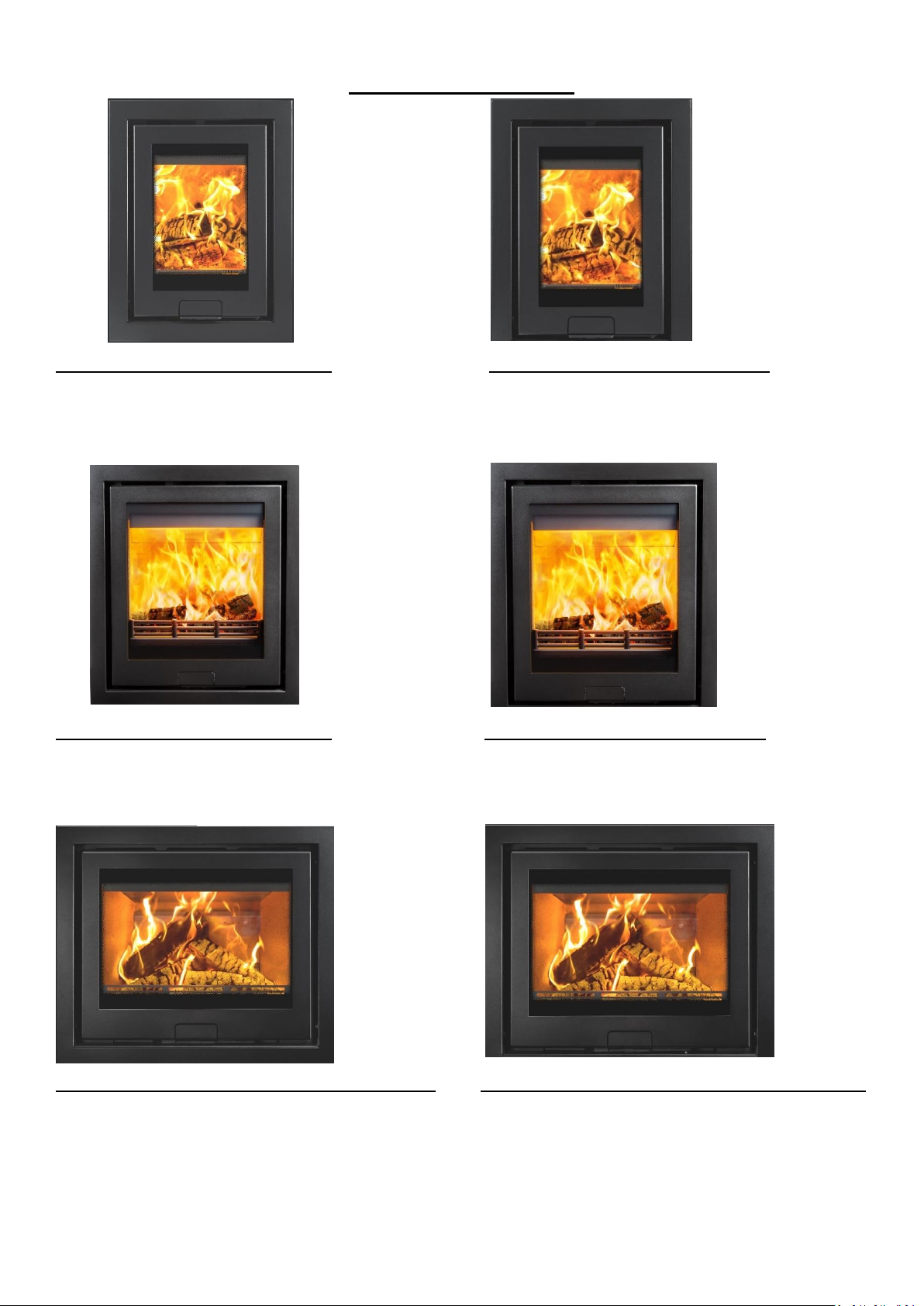
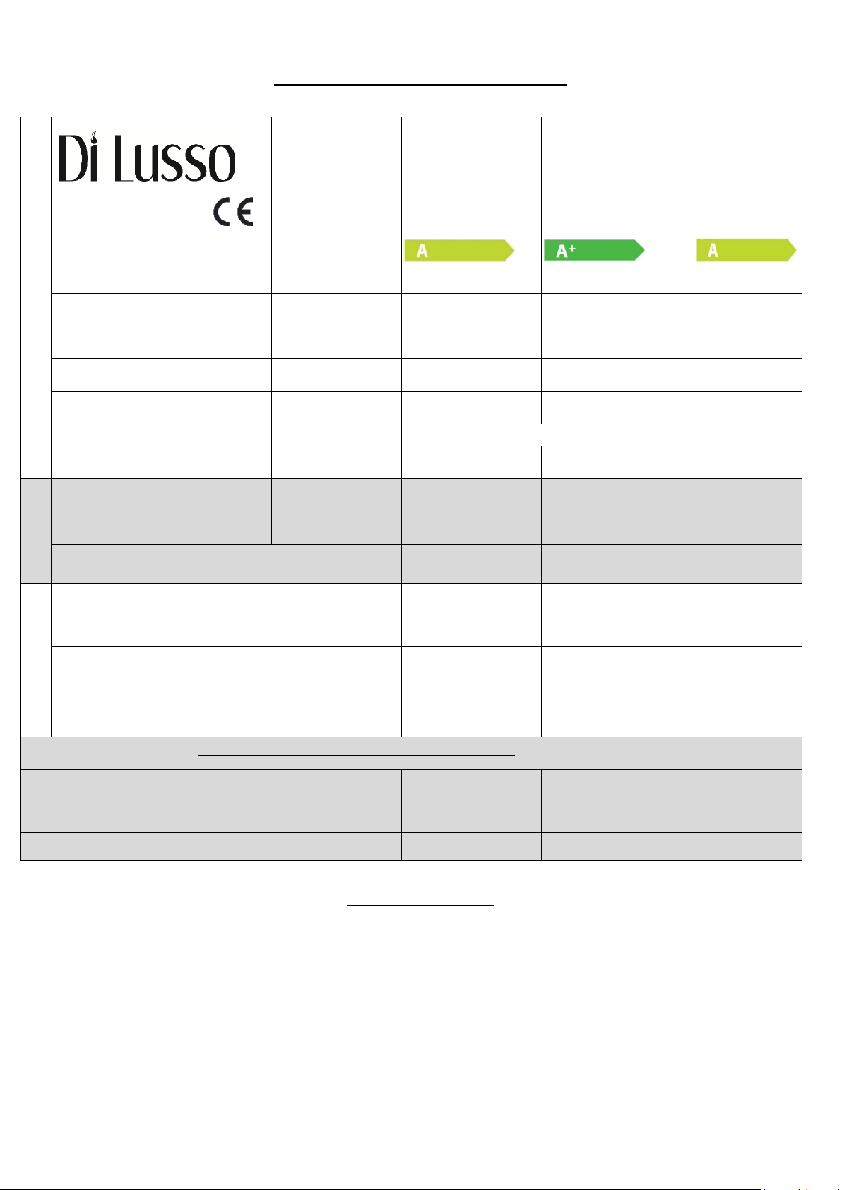
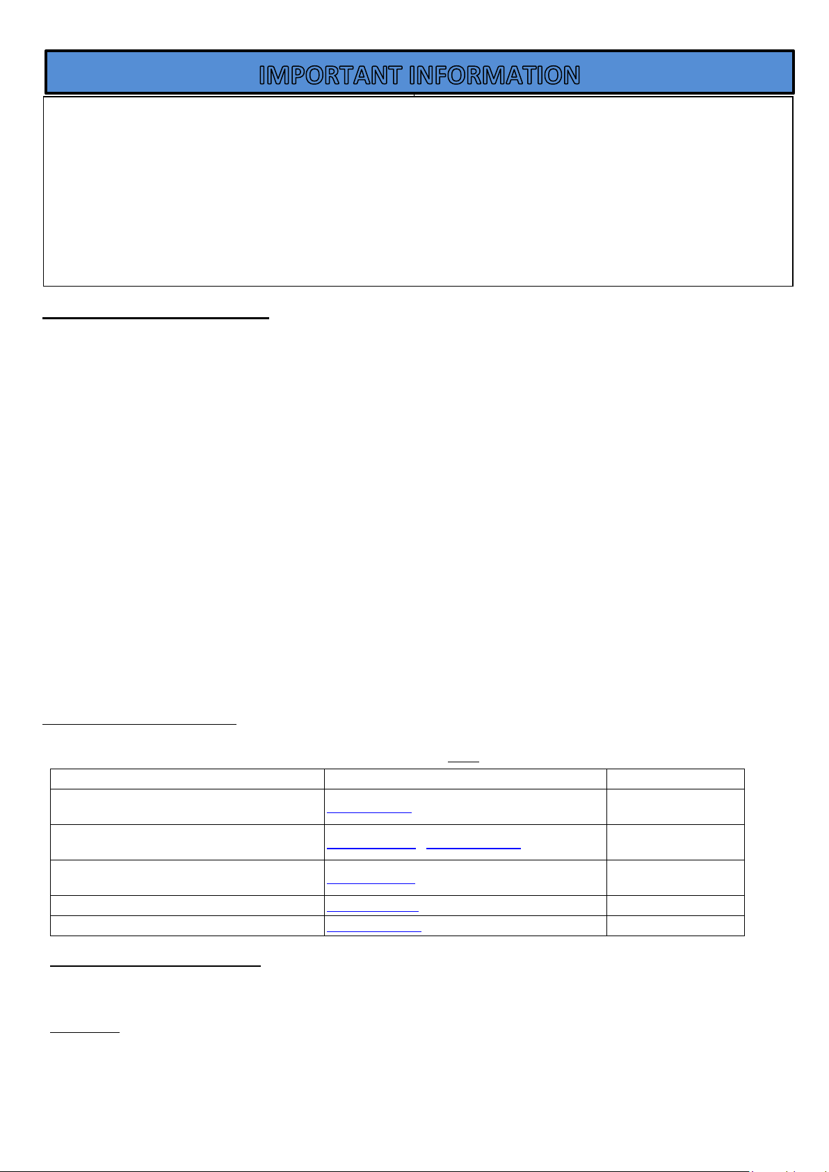
Eco R4 Inset
Eco R5 Inset
Eco R6 Inset
Eco R6 Slimline Inset
Wood Burning Inset Stove
Instructions for:
Installation/Operating/Maintenance/Servicing Instructions
JINEDLUIN REV B 27/03/2019
2
STOVE MODELS
ECO R4 INSET (FOUR-SIDED FRAME) ECO R4 INSET (THREE-SIDED FRAME)
STOVE - EDDLR04 STOVE – EDDLR04
FRAME – DLR4FP4B50 (BLACK) FRAME – DLR4FP3B50 (BLACK)
FRAME – DLR4FP4P50 (PEWTER) FRAME – DLR4FP3P50 (PEWTER)
ECO R5 INSET (FOUR-SIDED FRAME) ECO R5 INSET (THREE-SIDED FRAME)
STOVE – EDDLR05 STOVE – EDDLR05
FRAME – DLR5FP4B50 (BLACK) FRAME – DLR5FP3B50 (BLACK)
FRAME – DLR5FP4P50 (PEWTER) FRAME – DLR5FP3P50 (PEWTER)
ECO R6/R6 SLIMLINE INSET (FOUR-SIDED FRAME) ECO R6/R6 SLIMLINE INSET (THREE-SIDED FRAME)
STOVE – EDDLR06/EDDLR06S STOVE – EDDLR06/EDDLR06S
FRAME – DLR6FP4B50 (BLACK) FRAME – DLR6FP3B50 (BLACK)
FRAME – DRL6FP4P50 (PEWTER) FRAME – DLR6FP3P50 (PEWTER)

3
CONTENTS INDEX:
STOVE MODELS………………………………………………………………………………………………… 2
TECHNICAL SPECIFICATION……………………………………………………………………………… 4
GENERAL GUIDANCE………………………………………………………………………………………… 5/6
SAFETY……………………………………………………………………………………………………………… 6/7
INSTALLATION
APPLIANCE DIMENSIONS…………………………………………………………………………………… 7 - 9
FLUE REQUIREMENTS……………………………………………………………………………………….. 9/10
DI LUSSO ECO R4 INSTALLATION………………………………………………………………………. 10 - 14
DI LUSSO ECO R5 INSTALLATION………………………………………………………………………. 14 – 17
DI LUSSO ECO R6 INSTALLATION………………………………………………………………………. 17 - 19
FITTING THE STOVE – ALL ……………………………………….………………………………………. 19 - 27
DI LUSSO ECO R4 FLUE CONNECTION……………………………………………………………….. 21/22
DI LUSSO ECO R5 FLUE CONNECTION……………………………………………………………….. 22/23
DI LUSSO ECO R6/R6 SLIMLINE FLUE CONNECTION ……………………………………………. 23/24
DI LUSSO ECO R5/R6/R6 SLIMLINE ENCLOSURE INSTALLATION…………………………… 26 - 27
RE-ASSEMBLING THE STOVE……………………………………………………………………………… 31
OPERATING INSTRUCTIONS………………………………………………………………………………. 31 - 34
MAINTENANCE…………………………………………………………………………………………………. 34/35
TROUBLESHOOTING…………………………………………………………………………………………. 36/37
SPARES…………………………………………………………………………………………………………….. 38- 42
INSTALLATION AND COMMISSIONING CHECK LIST…………………………………………… 43
SERVICE RECORDS……………………………………………………………………………………………. 44
FULL WARRANTY INFORMATION……………………………………………………………………… 45/46
Welcome to the Hunter Stoves family and thank you for purchasing
an Eco Di Lusso Inset stove. This stove was designed and built to be
a high-performance heating appliance, and we hope it will bring
you great enjoyment. The natural environment is important to us,
so our stoves are manufactured to provide you with a clean and
efficient burn that will keep you warm through cold winter nights.
4
Technical Specification
Eco R4
Eco R5
Eco
R6/R6
Slimline
Energy Efficiency Class
Nominal Heat Output
Wood
4.9kW
6.3kW
6.2kW
Energy Efficiency
EEI
106
107
102
Efficiency
Wood
79%
81%
77%
Mean CO (@13% O₂)
Wood
0.09%
0.12%
0.09%
Appliance Mass
70kg
121kg
116kg
Recommended Fuels
Wood
Seasoned Wood (less than 20% moisture content)
Maximum Log Length
250mm
350mm
330mm
FLUES
Mean Flue Gas Temperature
Wood
226°C
269˚C
299˚C
Flue Gas Mass Flow
Wood
5.5 g/s
4.9 g/s
5.6 g/s
Flue Outlet Size (Top or Rear Option)
127mm
127mm
127mm
VENTILATION
- Where leakage is greater than 5m³/hour/m²
- Ventilation normally required = 550mm² per
kW output over 5kW
NONE
660mm²
715mm²
- Where leakage is less than or equal to
5m³/hour/m²
- Ventilation normally required = 550mm² per
kW output
2695mm²
3410mm²
3465mm²
Minimum Clearance to Combustible Material
At the sides of the stove
250mm (from
outside of frame)
450mm (from
outside of frame)
400mm
(from outside
of frame)
In front of the stove (to furniture etc.)
800mm
1100mm
1200mm
Smoke Control Areas
This appliance is only exempt for use in a smoke control area when fitted with a smoke control area kit (JDLU0401 –
R4) or (JDLU0501 – R5/R6). Find out if you are in a Smoke Control Area by contacting your Local Authority
5
General Guidance
It is important that your stove is correctly installed and operated as Hunter Stoves Group cannot accept responsibility
for any fault arising through incorrect installation, use, maintenance or servicing.
These instructions cover the basic principles to ensure satisfactory installation of the stove, although detail may need
slight modification to suit local site conditions.
The installation must comply with current Building Regulations, National and European Standards, Local Authority
Byelaws and other specifications or regulations as they affect the installation of the appliance.
The Building Regulations requirements may also be met by adopting the relevant recommendations in the current
issues of British Standards BS 8303 and BS EN 15287-1.
Only use approved fuels on this appliance. Information about this can be found on Pages 32.
This is a Domestic Appliance and must only be used in accordance with these instructions. Do not place articles that
are affected by high temperatures on, or near, this appliance. Do not place furniture or other items within 1 metre of
the front of this appliance. See the note on material clearances on pages – R4 – 10 - 12 and R5 – 14 - 16 and R6/R6
Slimline – 17 - 19.
Fitting a stove in a room which also contains an extractor fan and/or cooker hood should be avoided where possible. If
this is unavoidable, the suitability of the space for fitting this appliance must be decided at the discretion of a qualified
installer, and a flue draught interference test must be performed. Do not obstruct the ventilation required for the safe
use of this appliance.
Competent Persons Scheme
Members of the following schemes may self-certify the installation of this stove. If the installer is not a member
of one of these schemes, your local Building Control Department must approve the installation.
Health And Safety Precautions
Special care must be taken when installing the stove such that the requirements of the Health and Safety at Work
Act are met.
Packaging
All packaging supplied with this stove can be re-used or recycled. Please contact your local authority for information
on recycling schemes in your area.
Scheme
Web address
Telephone
APHC (Association of Plumbing and Heating
Contractors (Certification) Limited
www.aphc.co.uk
02476 470 626
Building Engineering Services Competence
Accreditation (BESCA Limited)
www.hvca.org.uk / www.besca.org.uk
0800 652 5533
HETAS Ltd (Heating Equipment Testing and Approval
Scheme)
www.hetas.co.uk
01462 634721
NAPIT Registration Ltd
www.napit.org.uk
0870 444 1392
NICEIC Group Ltd
www.niceic.org.uk
0800 013 0900
PLEASE READ THESE INSTRUCTIONS PRIOR TO INSTALLATION AND OPERATION. KEEP THESE
INSTRUCTIONS IN A SAFE PLACE FOR FUTURE REFERENCE AND SERVICING.
THIS APPLIANCE WILL BECOME VERY HOT WHEN USED IN ACCORDANCE WITH THESE INSTRUCTIONS,
HUNTER STOVES RECOMMEND THAT AN APPROVED GUARD IS USED TO PROTECT THE YOUNG, ELDERLY
OR INFIRM FROM HARM.
THE INSTALLER COMMISSIONING SHEET CAN BE FOUND ON THE BACK COVER. PLEASE ENSURE THAT IT IS
COMPLETED PRIOR TO USE.

6
Handling
Adequate facilities must be available for loading, unloading and site handling.
Fire Cement
Some types of fire cement are caustic and should not be allowed to come into contact with the skin. In case of
contact, wash immediately with plenty of water.
Asbetos
This stove contains no asbestos. If there is a possibility of disturbing any asbestos in the course of installation then
please seek specialist guidance and use appropriate protective equipment.
Metal Parts
When installing or servicing this stove, care should be taken to avoid the possibility of personal injury.
Air Supply
The room or space containing this appliance should have purpose provided ventilation (where necessary) in
accordance with Building Regulations. Due consideration should be given to air requirements for any other appliance
in the same room or space. Any air opening must be kept clear from blockage or obstruction.
Modification
No unauthorised modification of this appliance should be carried out.
Safety
WARNING – This appliance will be hot when in operation and due care should be taken. The supplied operating tool
or gloves may be used to open the door and operate the air controls.
Aerosols
Do not use an aerosol spray on or near the stove when it is alight.
Fires Can Be Dangerous
Always use a fireguard in the presence of children, the elderly or the infirm. The fireguard should be manufactured in
accordance with BS8423 – Fireguards for use with solid fuel appliances.
Do Not Over-Fire
It is possible to fire the stove beyond its design capacity. This could damage the stove so watch for signs of overfiring. If any part of the stove starts to glow red, the stove is in an over-fire situation and the controls should be
adjusted accordingly. Never leave the stove unattended for lengthy periods without first adjusting the controls to a
safe setting. Careful air supply control should be exercised at all times.
Fume Emission
Properly installed and operated, this appliance will not emit fumes. Occasional fumes from de-ashing and refueling
may occur. Persistent fume emission must not be tolerated.
This appliance should not be operated with the door open.
If fume emission does persist then the following action should be taken immediately –
• Open Doors and windows to ventilate room.
• Let the fire out or eject and safely dispose of fuel from the appliance.
• Check for flue/chimney blockage and clean if required.
• Do not attempt to relight the fire until the cause has been identified and corrected.
• If necessary, seek professional advice.
Adverse Weather
In a small number of installations, occasional local weather conditions (e.g. wind from a particular direction) may
cause downdraught in the flue and the stove to emit fumes. In these circumstances, the stove should not be used. A
professional flue installer will be able to advise on solutions to this problem (e.g. anti-downdraught cowl).
7
IN THE EVENT OF A CHIMNEY FIRE -
• Raise the alarm
• Call the Fire Brigade
• Close appliance air controls
• Move furniture, ornaments etc. away
• Place a fireguard in front of stove
• Check the chimney breast for signs of excessive heat.
If the wall is becoming excessively hot, move furniture away. Ensure the Fire Brigade can gain access to your roof
space in order to check for fire spread.
Installation
(N.B. All dimensions are in Millimetres)
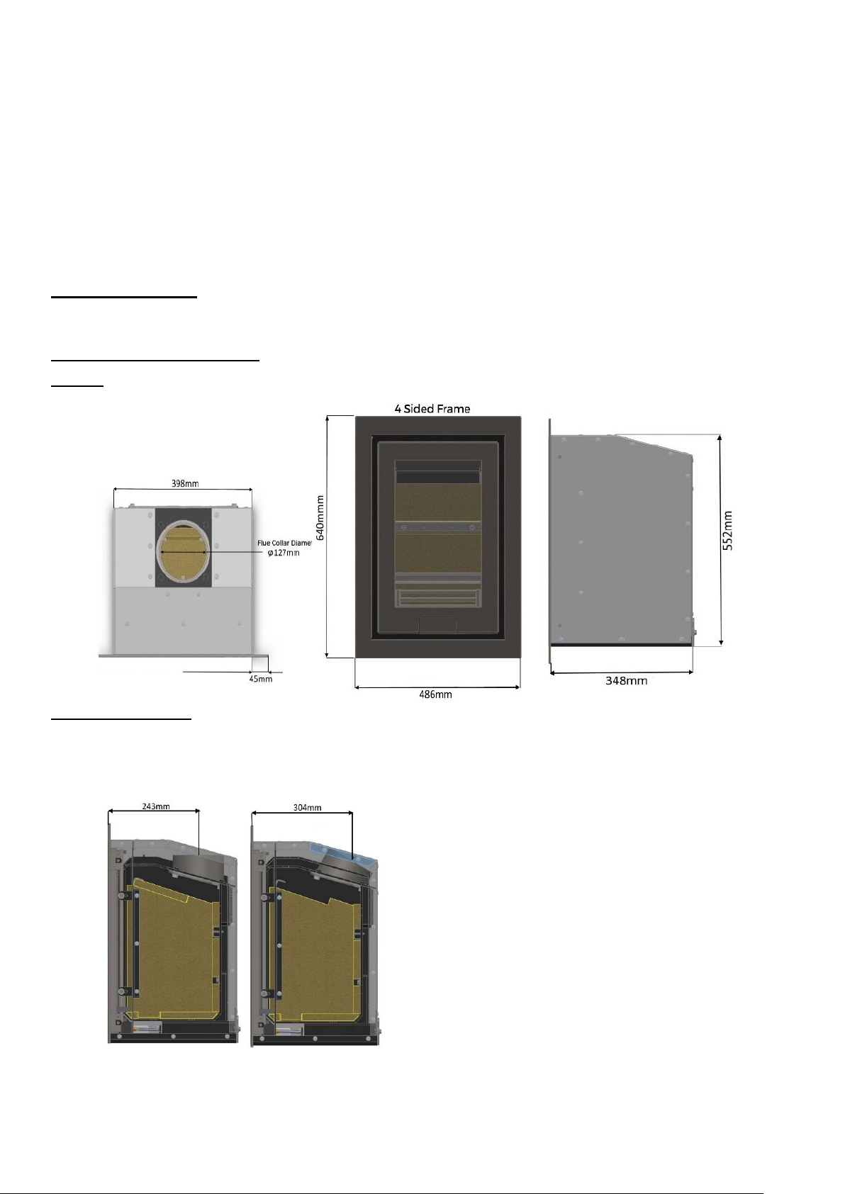
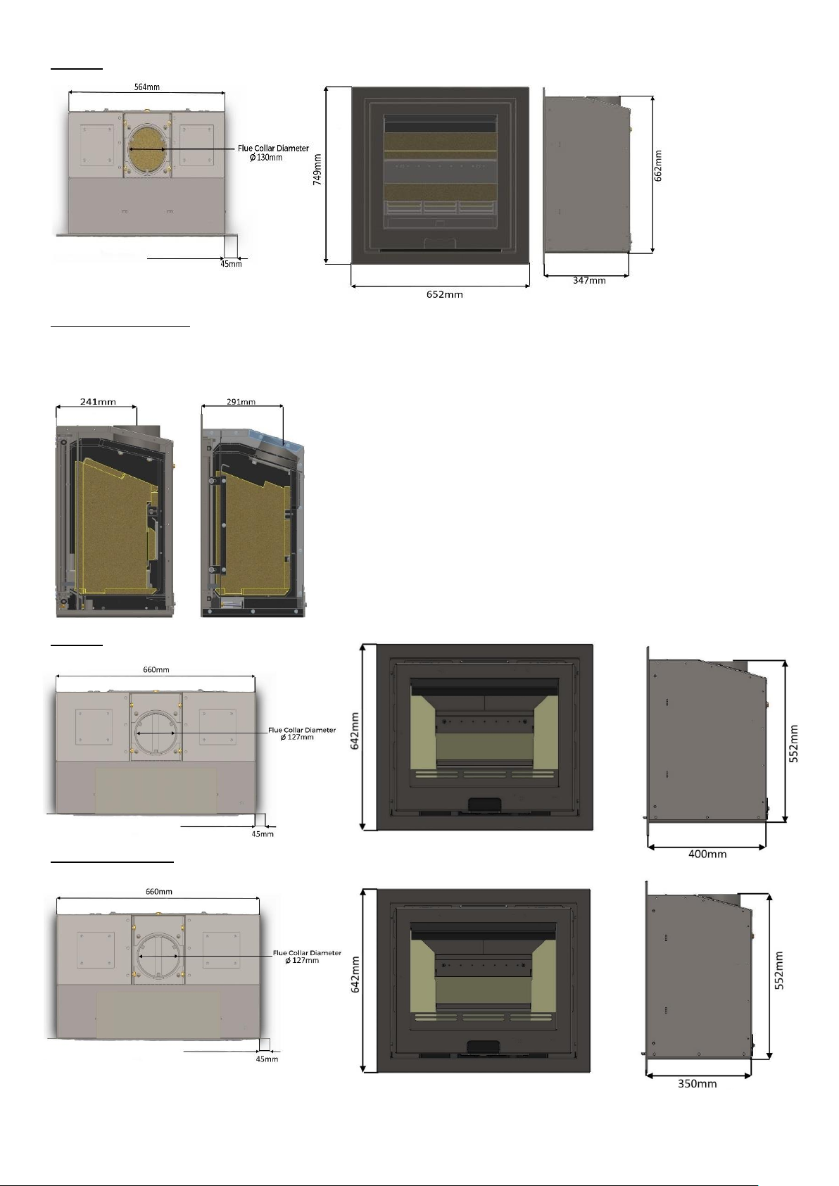
Appliance Dimensions
ECO R4
Flue Outlet Position
The flue outlet angle and position are determined by the orientation of the flue collar. The outlet can be either vertical
or leant backwards by 30°. To change the angle, rotate the flue collar by 180°. The effective centre dimensions in
millimeters are shown below.
8
ECO R5
Flue Outlet Position
The flue outlet angle and position are determined by the orientation of the flue collar. The outlet can be either vertical
or leant backwards by 30°. To change the angle, rotate the flue collar by 180°. The effective
centre dimensions in millimetres are shown below.
ECO R6
ECO R6 SLIMLINE

9
Flue Outlet Position
The flue outlet angle and position are determined by the orientation of the flue collar. The outlet can be either
vertical or leant backwards by 30°. To change the angle, rotate the flue collar by 180°. The effective centre
dimensions in millimeters are shown below.
ECO R6 ECO R6 SLIMLINE
Flue Requirements
The flue serving this appliance must be dry, free from cracks and obstructions and be in accordance with the
designations shown in Table 1.
The diameter of the flue should not be less than 127mm and not more than 200mm. If these requirements are not
met the chimney should be lined by a suitable method. If there is no existing chimney, then either a prefabricated
block chimney in accordance with Building Regulations Approved Document J or a twin-walled insulated stainless-steel
flue to BS EN 1856 can be used. These chimneys must be fitted in accordance with the manufacturer’s instructions
and Building Regulations.
The chimney/flue should have a vertical height of at least 4.5 metres and should terminate in accordance with Table
2.
If the chimney is believed to have previously served an open fire installation, it is possible that the higher flue gas
temperature from the stove may loosen deposits that were previously firmly adhered, with the consequent risk of
flue blockage. It is therefore recommended that the chimney is swept a second time within a month of regular use
after installation.
If you have any doubts about the suitability of your chimney, consult your local dealer/stockist.
Both the chimney and flue pipe must be accessible for cleaning and if ANY part of the chimney cannot be reached
through the stove (with baffle removed), a soot door must be fitted in a suitable position.
Flue Type
Minimum Designation
Masonry or flue block flue with liner
T400 N2 D3 G (BS EN 1443:2003)
Clay Flue Blocks
FB1 N2 (BS EN 1806:2006)
Clay/Ceramic Liners
B1 N2 (BS EN 1457:2009)
Concrete Liners
B2 (BS EN 1857:2003)
Factory Made Metal Chimney
T400 N2 D3 G (BS EN 1856-1:2003)
Table 1 – Minimum Flue Designations
10
Table 2.
Flue Draught
If the draught exceeds the recommended maximum, a draught stabiliser must be fitted so that the rate of burning
can be controlled and to prevent over firing.
If the reading is less than the recommended minimum, then the performance of the appliance will be compromised.
The flue draught should be checked under fire at high output.
Minimum Draught – 1.2mm Water Gauge
Maximum Draught – 2.5mm Water Gauge
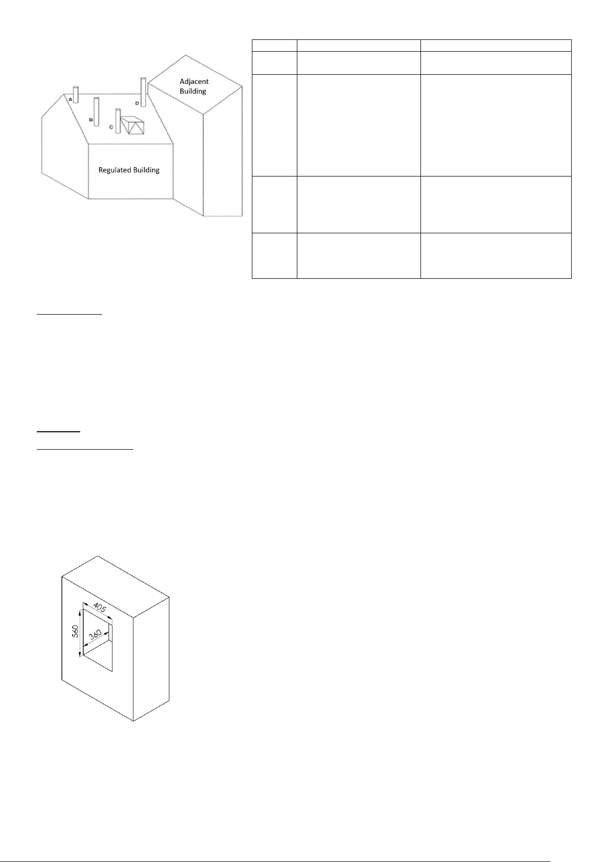
ECO R4
Appliance Opening
This stove must be fitted on a hearth or base with adequate load-bearing capacity.
The opening into which this stove is fitted should be constructed wholly from non-combustible materials. The
dimensions of the opening should be at least those shown in the diagram. Ensure there is a sufficient overlap where
the convection chamber flange meets the face of the opening. If not, either the opening should be made smaller, or
a suitable fire surround should be fitted to reduce the opening dimensions. This appliance will fit into a standard 16”
fireplace opening if the clay fire back is removed.
Any non-combustible walls within 50mm of this appliance should be at least 200mm thick and should extend at
least 300mm above the top of the appliance and at least 1.2 metres above the hearth. Any walls more than 50mm
from the appliance may be reduced to a thickness of 75mm. Ensure the inter-connecting flue pipe also has
adequate clearances to combustible materials.
Terminal
Position
Clearances to Flue Outlet
A
At or within 600mm of the
ridge
At least 600m above the ridge
B
Elsewhere on a roof (whether
pitched or flat)
At least 2300mm horizontally from
the nearest point on the weather
surface and:
a) At least 1000mm above the
highest point of intersection of
the chimney and the weather
surface or
b) At least as high as the ridge
C
Below (on a pitched roof) or
within 2300mm horizontally
to an openable roof light,
dormer window or other
opening.
At least 1000mm above the top of
the opening.
D
Within 2300mm of an
adjoining or adjacent
building, whether or not
beyond the boundary.
At least 600mm above any part of
the adjacent building within
2300mm

11
The wall above the stove will become hot and should therefore be finished in a heat resistant plaster.
IMPORTANT Do not hang pictures, electrical equipment or ornaments above the stove, as these could be damaged
and could potentially create a fire hazard.
Please check the suitability of any fireplace/surround for closed solid fuel appliances before installation. Di Lusso
cannot be held responsible for any fault arising through incorrect use or installation. Fire surround back panels
suitable for solid fuel are usually in three sections and slabbed. Many fire surrounds are suitable only for use with
gas and electric fires and therefore not suitable for solid fuel.
Direct Air Adaptor
If fitting the direct air adaptor kit, the opening depth may need to be increased. Read the instructions supplied with
the kit before proceeding.
Hearth Requirements
A constructional hearth with a minimum thickness of 225mm should be provided. The constructional hearth should
be made of solid non-combustible material and can include any solid non-combustible floor. The boundary of the
hearth must be clearly marked. This can be done by adding a super-imposed hearth on top of the constructional
hearth – e.g. a slate slab on top of a solid concrete floor.
Appliances installed with the base plate lower than 300mm above the hearth should have a constructional hearth
extending to at least 300mm in front of the stove (as per Building Regulations) however we would recommend
400mm and 150mm at the sides.

12
Appliances installed on a surface more than 300mm above the hearth require a constructional hearth with a depth
of 225mm in front of the stove. The base on which the appliance is mounted should be an extension of the
constructional hearth – i.e. all material between the stove base and the constructional hearth must be solid-
noncombustible material.
Clearances To Combustible Materials
There should be no combustible materials for a distance of 250mm either side of the stove or 680mm above. No
combustible furniture should be placed any closer than 800mm from the front of the stove.
Allow sufficient clearance between the stove and pictures, electrical equipment or ornaments etc., as these could
be damaged and could potentially create a fire hazard.
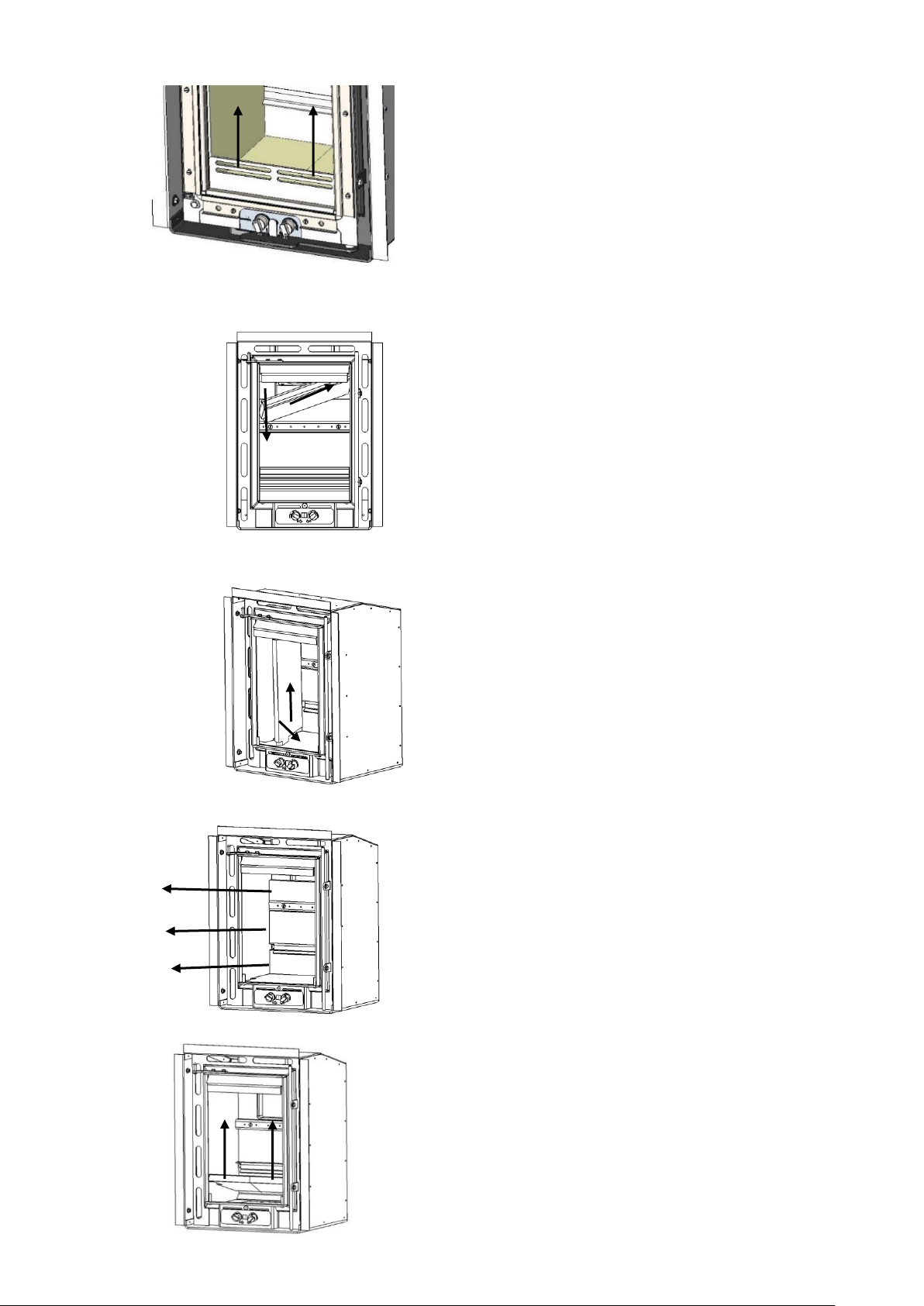
Removing Internal Components (All)
All internal components must be removed prior to fitting the stove. This will make handling the stove easier; allow
access to fixings and the flue outlet; as well as protect the internal components from damage during the
installation process.
1. To open the stove door, pull the door lever towards you to release from the magnet. Swing the handle out to the
right until the mechanism engages and the door catch is released.
N.B. When closing the door keep the door handle out to the right
until the door is closed.
13
2. Remove the log retainer by lifting it clear of the two support pins.
3. Remove the baffle brick (Eco R4/Eco R5 by lifting it up, sliding it to the right and then lowering the left-hand
edge into the firebox. For the Eco R6/R6 Slimline slide both baffle plates to the centre with left hand baffle
on top of right-hand baffle and lift out of stove together.
4. Remove the two side bricks by lifting them up to release them from the slots in the base brick. Swing the
bricks into the centre and remove them from the stove.
5. Remove the three rear brick sections (Eco R4) and two rear bricks (Eco R5/Eco R6) noting their positions and
orientation.
6. Lift up and remove the two base bricks.
14
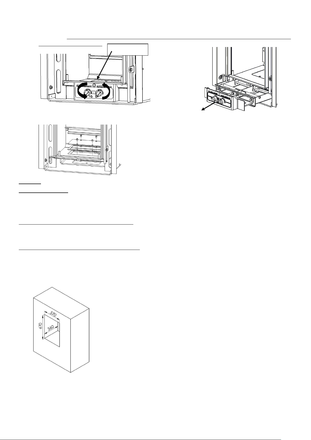
7. Remove the Air Valve Cassette by removing the socket screw holding it in place, turning both air controls to
the fully open position (clockwise) and then gently pulling on the fascia to slide the cassette out from under
the firebox. N.B. DO NOT Remove the Air Valve Cassette with the controls in the closed position as this will
damage the valve gaskets.
8. Undo the four countersunk screws and remove the base fixing access plate and gasket.
ECO R5
Appliance Opening
Important! This appliance may be installed either into a solid non-combustible opening or into an enclosure
fabricated from non-combustible sheet material as per the specifications in these instructions. For installation
instructions covering the approved enclosure design please proceed to 26.
Direct Air Adaptor And Convection Duct Kits
If fitting either the Direct Air Adaptor Kit or Convection Duct Kit the dimensions of the opening may need to be
altered. Read the instructions supplied with the kit before proceeding.
Installation Into A Solid Non-Combustible Wall
This stove must be fitted on a hearth or base with adequate load bearing capacity. The opening into which this stove
is fitted should be constructed wholly from non-combustible materials. The dimensions of the opening should be at
least those shown in the diagram. Ensure there is a sufficient overlap where the convection chamber flange meets
the face of the opening. If not, either the opening should be made smaller, or a suitable fire surround should be
fitted to reduce the opening dimensions.
Any non-combustible walls within 50mm of this appliance should be at least 200mm thick and should extend at
least 300mm above the top of the appliance and at least 1.2 metres above the hearth. Any walls more than 50mm
from the appliance may be reduced to a thickness of 75mm. Ensure the inter-connecting flue pipe also has
adequate clearances to combustible materials.
Socket screw
 Loading...