

Page 1
*Electricians are recommended to tick off all items on the quick
checklist and fill out their details onto the back page of the Fan
Owner Warranty & Operations Manual after installation
National Warranty Line
1300 360 280
Monday to Friday from 9am to 5pm EST
Only available within Australia
Hunter Pacific International Pty Ltd, Building 8, 256 New Line Road, Dural NSW 2158 Australia
ABN :18 063 521 666
ELECTRICIANS - TO PROTECT YOUR CUSTOMER’S WARRANTY, PLEASE READ
PAGE 2 OF THIS BOOKLET PRIOR TO THE INSTALLATION OF THIS PRODUCT.
CEILING FAN MUST BE INSTALLED
BY A LICENSED ELECTRICIAN
(NO OTHER PERSONS SHOULD ATTEMPT TO INSTALL THIS FAN)
Installation Manual
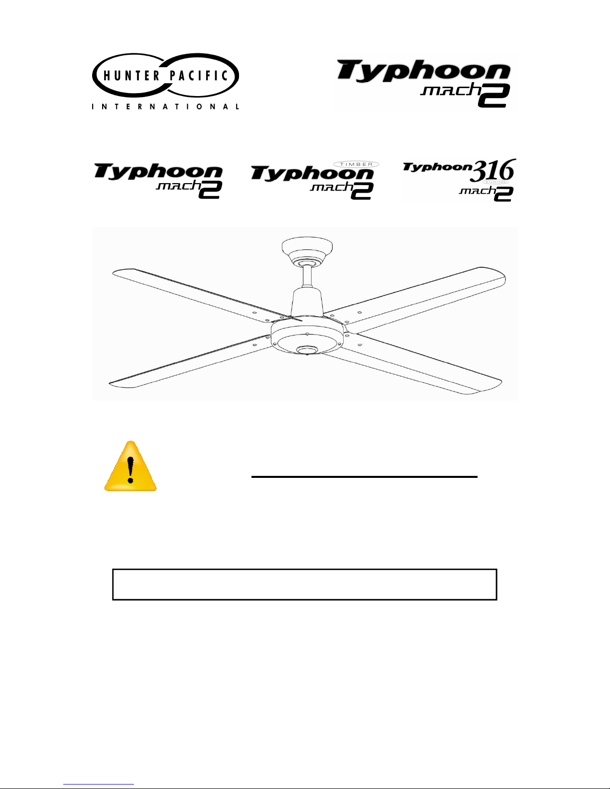
Note: Picture is of Typhoon Mach 2 Metal and is for illustrative purposes only
®
®
Page 2
2
IMPORTANT INFORMATION
EVERYONE MUST READ PRIOR TO INSTALLATION
1. Distributor and installer details and purchase receipts are essential for on-site warranty claims
and must be presented to repair personnel, make sure you record your details in the Fan Owner
Warranty and Operations Manual.
2. Fans and fixed wiring products must only be installed by persons who are appropriately licensed
by the applicable State regulatory body. Therefore, to protect our repair personnel, on-site
warranty claims will not be accepted if products have been installed by unlicensed persons.
3.
Damage caused by incorrect installation, force-majeure, electrical surges, lightning, power grid
fluctuations, water or by connection to alternative power supply sources (such as solar inverters,
etc.) is not eligible for warranty repair.
4.
When products are installed in a location requiring special access equipment (such as
scaffolding or scissor lifts, etc) the cost of providing, installing and operating special access
equipment must be borne by the site owner for all service or warranty work.
5. “This appliance is not intended for use by persons (including children) with reduced physical,
sensory or mental capabilities, or lack of experience and knowledge, unless they have been
given supervision or instruction concerning use of the appliance by a person responsible for their
safety. Children should be supervised to ensure that they do not play with the appliance.”
(AS/NZS 60335.1 C1.7.12)
DANGER: Contact with ceiling fan blades can cause serious injury or death.
To electricians and installers. The Australian Competition and Consumer Law 2010 mandates
consumer protection against defects or poor workmanship in provision of services (such as
installing a ceiling fan). To protect yourself and the consumer these instructions must be
followed. Failure to do so may result in the consumer making a claim against you for
consequential loss or damage.
6. A double pole isolation switch providing full disconnection of both fan and light must be fitted in
accordance with the wiring rules (AS/NZS 60335.1 C1.7.12.2). An RCD may fulfill this function if
suitably labeled.
For safety, and to protect your warranty, the following must be taken into account when
installing and operating the product(s):
IF THERE ARE ANY PROBLEMS WITH THE PRODUCT AT TIME OF
INSTALLATION THE INSTALLER MUST CONTACT THE WARRANTY
HOT LINE NUMBER 1300 360 280 BEFORE LEAVING THE JOB
SITE. PLEASE DO NOT REMOVE THE FAN FROM THE CEILING
ONCE INSTALLED UNLESS INSTRUCTED TO DO SO.
(a)
DO NOT USE SOLID-STATE WALL CONTROLLERS. Neither leading nor lagging edge
controllers will give satisfactory performance. Wall controls must only be types approved for
use by Hunter Pacific International.
(b)
The fan, light and bracket must be earthed.
(c)
Fan and light must be run from the same final circuit.
(d)
Mounting bracket must be firmly screwed to a solid structure such as a concrete ceiling,
steel structure or timber framing. If additional bracing is added it must be firmly secured to
the rafters and not left floating on the ceiling. Special mounts, such as T-hooks, are
available for certain types of installation.
(e)
After installation, fan blades must be at least 2.1 m (7 feet) above floor level.
Page 3
3
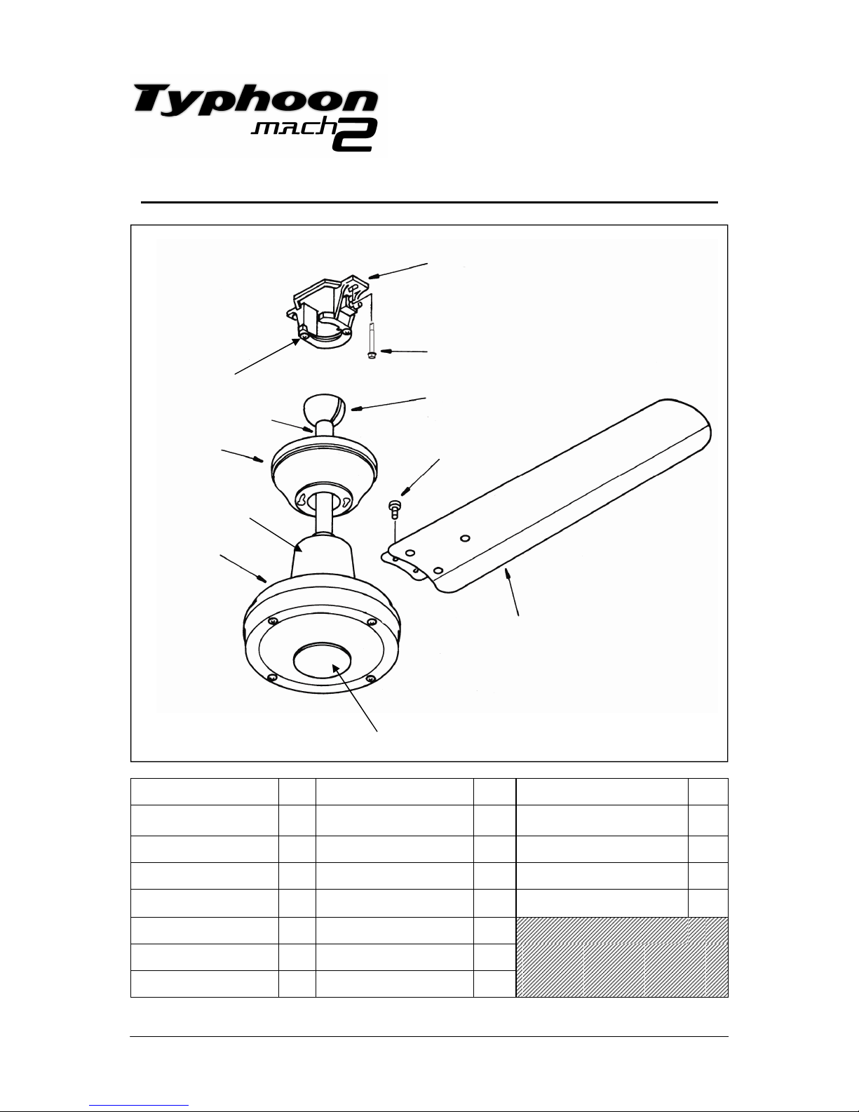
Parts List - Typhoon Mach 2 Metal and 316 Stainless Steel
Hanger Bracket
Hex Head Screw
Ball Joint
Blade Screw
Blade
Top
Canopy
Motor
Housing
Installation
Manual
Part Qty Part Qty Part Qty
Hanger Bracket 1
Down Rod
(21mm Diameter)
1 Blade Screws 8
Hex Head Screw 2 Down Rod Pin 1 Blade Washers 8
Top Canopy 1 Down Rod Short Screw 2 Wall Speed Capacitor 1
Top Canopy Screws 2 Canopy Cover 1 HPI Wall Controller 1
Ball Joint 1 Motor Housing 1
Ball Joint Screw 1 Base Plate 1
Ball Joint Pin 1 Blades 4
Base Plate
Canopy
Cover
Down Rod
Top
Canopy
Screws
Page 4
4
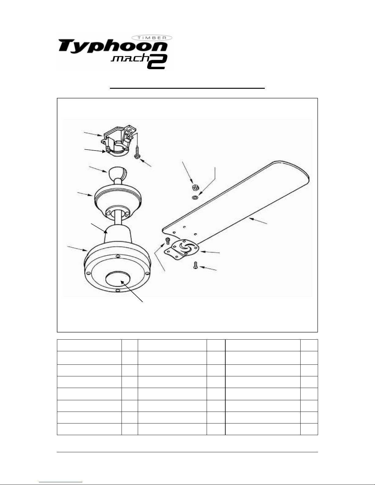
Hanger
Bracket
Hex Head
Screw
Ball
Joint
Blade Nut
Blade
Top
Canopy
Motor
Housing
Blade Washer
Blade Holder
Blade Screw
Blade
Holder
Screw
Installation
Manual
Parts List - Typhoon Mach 2 Timber
Part Qty Part Qty Part Qty
Hanger Bracket 1
Down Rod
(21mm Diameter)
1 Blade Holders 4
Hex Head Screw 2 Down Rod Pin 1 Blade Holder Screws 8
Top Canopy 1 Down Rod Short Screw 2 Blade Screws 16
Top Canopy Screws 2 Canopy Cover 1 Blade Washers 16
Ball Joint 1 Motor Housing 1 Blade Nuts 16
Ball Joint Screw 1 Base Plate 1 Wall Speed Capacitor
Ball Joint Pin 1 Blades 4 1 HPI Wall Controller 1
Canopy
Cover
Top
Canopy
Screws
Base Plate
Page 5
5
Installation Instructions
(Assembling the fan)
NOTE: If an extension down rod needs to be installed please go to page 9.
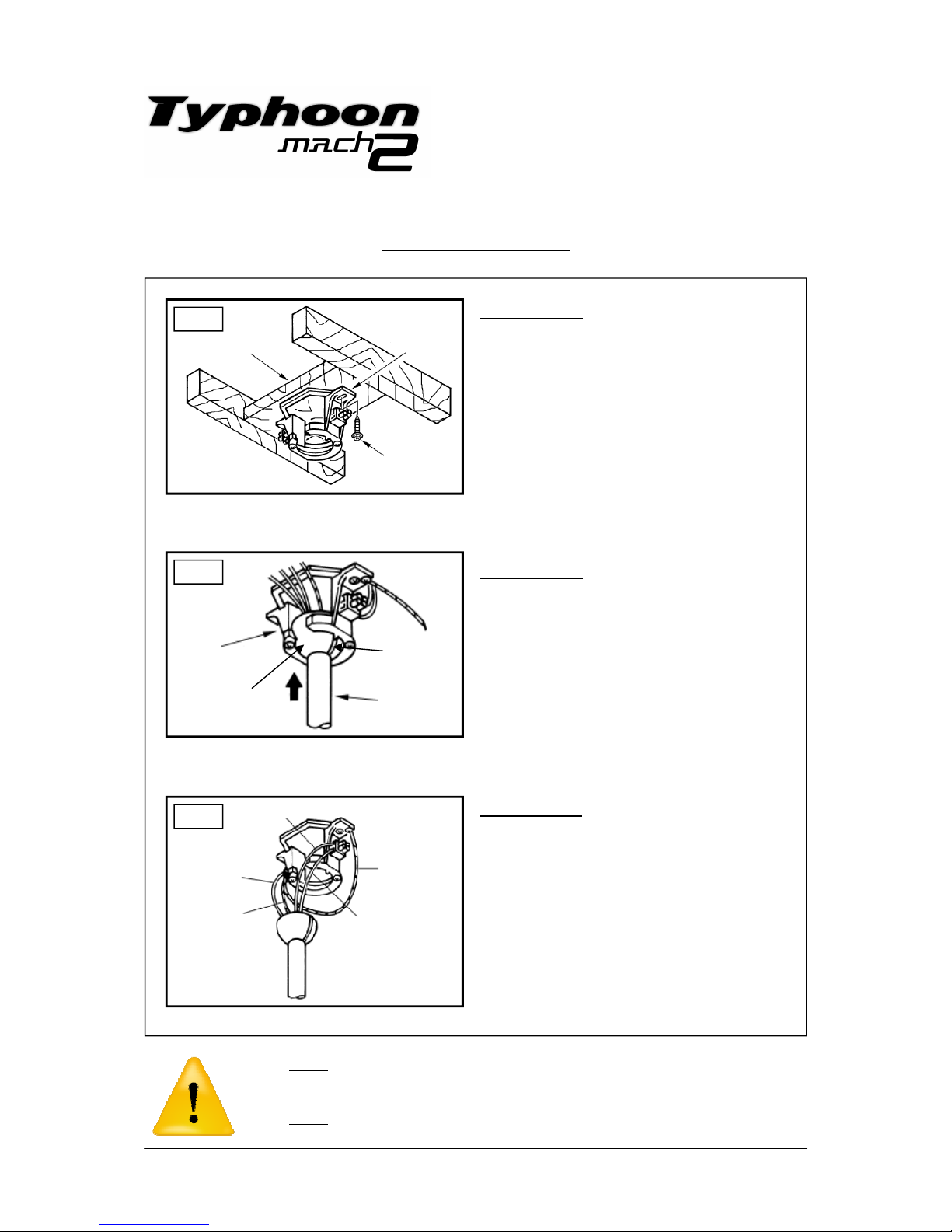
STEP 1 (Fig. 1)
a) Drill a hole in the timber nogging for wiring.
b) Secure the hanger bracket onto the timber
nogging, using the two hex head screws
provided. The timber nogging should be
supplied by the installing electrician and must
be supported between the two ceiling joists as
shown in the diagram.
Fig. 1
Timber
Nogging
Hex Head Screw
Hanger
Bracket
STEP 2 (Fig. 2)
a) Hang the ball joint into the hanger bracket.
Ensure the groove on the hanger bracket is
locked into the slot on the ball joint.
(This is important to ensure the fan will not
wobble and the weight of the fan is
supported).
Hanger
Bracket
Down
Rod
Fig. 2
Groove
Ball
Joint
Fig. 3
Green
Earth Wires
Brown
Blue
Red/White
Earth
1. Do not attempt to operate the fan (or optional light kit) with any wall control that is not approved by
Hunter Pacific International for use with its fans. DO NOT use solid state controllers. The use of
unapproved controllers may void your warranty.
2. Do not
mix blade sets from one fan to another as this may upset the balance of the fan. If only one
blade is damaged you are still required to replace with a new set.
Installation
Manual
STEP 3 (Fig. 3)
a) Connect wires from the fan with wires in
the ceiling.
b) Make sure earth wires are also connected.
c) Connect light wires (red/white) if a light
fitting is going to be used. (Cap seal light
wires if a light fitting is not going to be used).
NOTE: Terminal Block shown on bracket may
not be supplied with all models.
Page 6
6
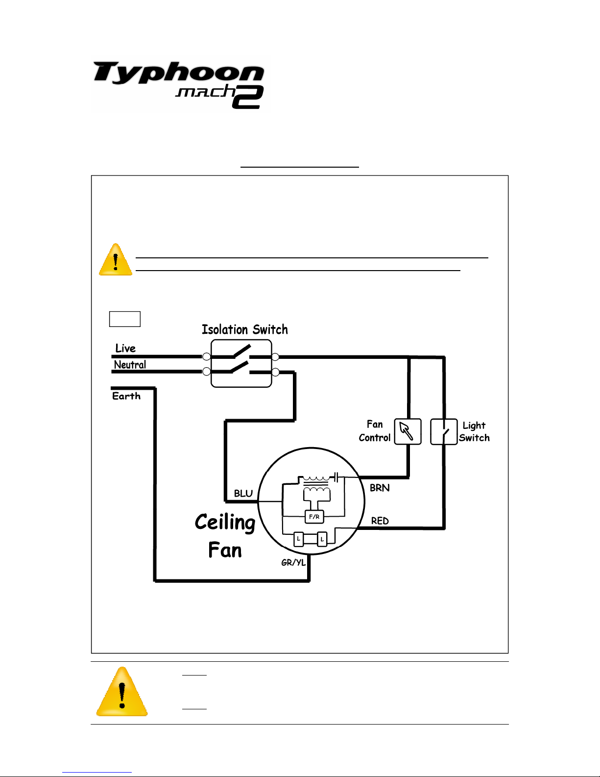
Wiring Instructions (with and without accessory light)
WARNING: To comply with AS/NZS 60335.1 a Double Pole Isolation
switch must be fitted in series with the supply of this product.
(an RCD may fulfill this function if suitably labeled)
Fig. 4
Installation Instructions
(Assembling the fan)
1. Do not attempt to operate the fan (or optional light kit) with any wall control that is not approved by
Hunter Pacific International for use with its fans. DO NOT use solid state controllers. The use of
unapproved controllers may void your warranty.
2. Do not
mix blade sets from one fan to another as this may upset the balance of the fan. If only one
blade is damaged you are still required to replace with a new set.
Installation
Manual
Page 7
7
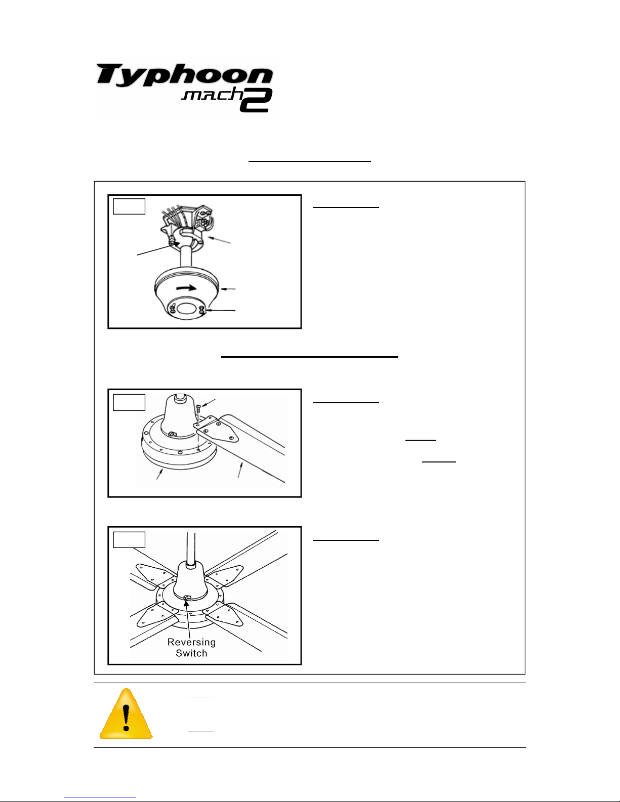
STEP 5 (Fig. 5)
a) Loosen canopy screws half way
b) Slide canopy cover up and over the
hanger bracket and position canopy screws
through the keyway in canopy cover .
c) Rotate the canopy clockwise and tighten
screws until canopy cover is tightly held.
d) Check rim of canopy is not touching the
ceiling. Add packing washers between canopy
and bracket to lower canopy
Fig. 5
Fig. 6
Hanger
Bracket
Top Canopy
STEP 6 (Fig. 6)
a) Attach blades to the motor housing using
the 2 screws provided. Tighten the Blade
Holder Screws firmly. Do not use power tools.
b) Repeat this step for all four blades. Install
each blade individually. Do not mix blades
from different fans as this can upset the
balance of the fan.
Motor Housing
Canopy Screw
Blade Holder
Screw
Blade
Ball
Joint
Installation Instructions
(Assembling the fan)
NOTE: If installing an Accessory Light refer to the light installation instructions enclosed in the light kit
1. Do not attempt to operate the fan (or optional light kit) with any wall control that is not approved by
Hunter Pacific International for use with its fans. DO NOT use solid state controllers. The use of
unapproved controllers may void your warranty.
2. Do not
mix blade sets from one fan to another as this may upset the balance of the fan. If only one
blade is damaged you are still required to replace with a new set.
Installation
Manual
Attaching the blades (Metal)
If attaching Timber blades please turn to page 8
STEP 7 (Fig. 7)
a) Check to ensure the reverse switch is
locked into position. Make sure it is either set
in the Summer or Winter position.
b) Test and ensure fan is operating correctly
on all three speeds in both forward and
reverse.
Fig. 7
Page 8
8
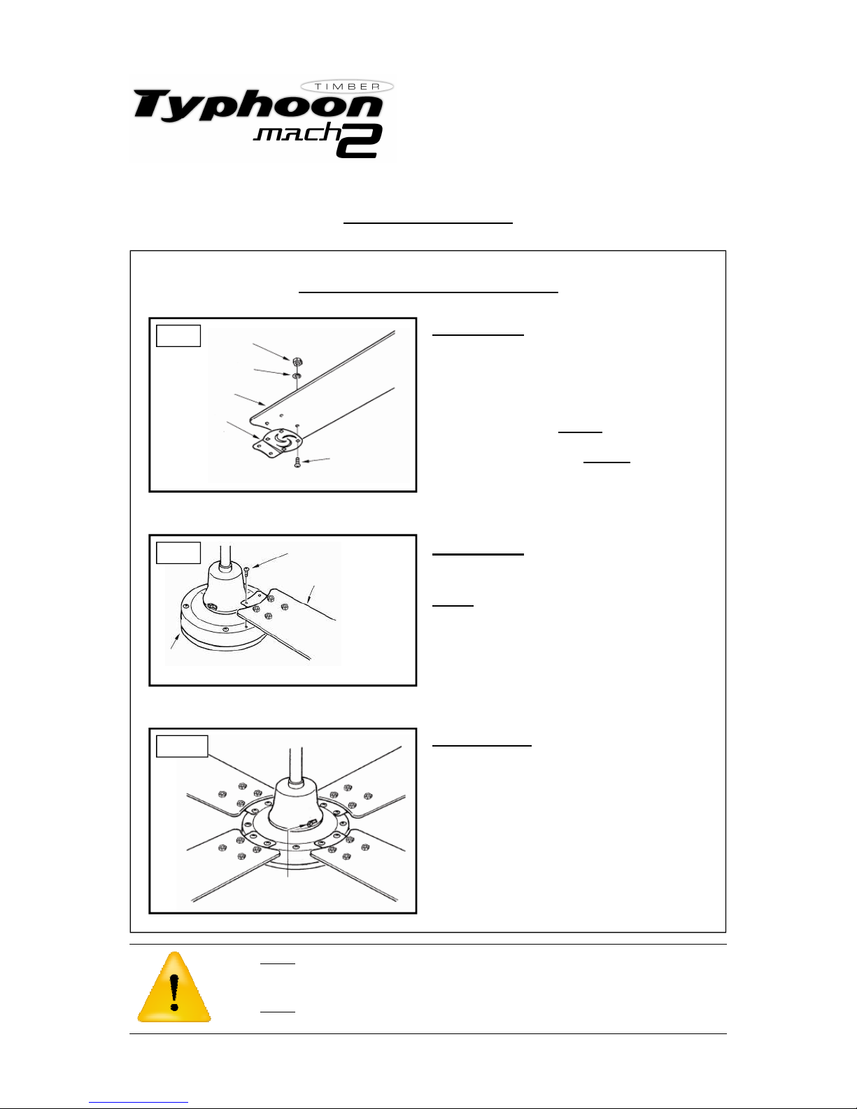
Motor
Housing
Blade
Fig. 9
STEP 7 (Fig. 9)
a) Attach blades with blade holders to the
motor housing using the 2 screws provided.
Do not use power tools.
b) Repeat this procedure for the other 3
blades.
Blade Holder Screw
Installation Instructions
(Assembling the fan)
1. Do not attempt to operate the fan (or optional light kit) with any wall control that is not approved by
Hunter Pacific International for use with its fans. DO NOT use solid state controllers. The use of
unapproved controllers may void your warranty.
2. Do not
mix blade sets from one fan to another as this may upset the balance of the fan. If only one
blade is damaged you are still required to replace with a new set.
Installation
Manual
Attaching the blades (Timber)
STEP 8 (Fig. 10)
a) Check to ensure the reverse switch is
locked into position. Make sure it is either set
in the Summer or Winter position.
b) Test and ensure fan is operating correctly
on all three speeds in both forward and
reverse.
Fig. 10
Reverse
Switch
Fig. 8
STEP 6 (Fig. 8)
a) Place Blade onto Blade Holder
b) Insert Blade Screw through Blade Holder
and Blade
c) Place washer over Blade screw and
thread nut onto Blade Screw. Now tighten the
Blade Screws firmly. Do not use power tools.
Repeat this step for all four blades. Install
each blade individually. Do not mix blades
from different fans as this can upset the
balance of the fan.
Blade
Screw
Blade
Holder
Blade
Nut
Washer
Page 9
9
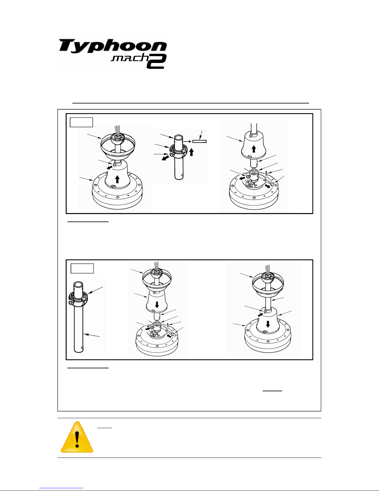
Step 1 (Fig. 11)
a) Loosen screws holding the Canopy Cover and Ball Joint.
b) Loosen the down rod screws and unlock the cotter pin to remove the standard down rod
from the motor housing.
c) Remove Ball Joint Pin and slide off Ball Joint, Top Canopy and Canopy Cover.
Step 2 (Fig. 12)
a) Now install the extension rod in reverse order of Step 1 to secure the extension down rod
to the fan.
b) Tighten Canopy Cover screws to Down Rod to prevent it from rattling. Do not use power
tools.
Canopy
Cover
Screw
Connection Collar
Down Rod Pin
Cotter Pin
Fig. 11
Down Rod
NOTE: If the extension rod needs to be shortened, cut the rod to the required length and drill the appropriate hole size to fit the ball joint pin. The cut end of the rod should be used on the ball joint end only.
The hole for the pin must be exactly positioned to pass through the centre of the rod, drilled straight and
horizontal. When installing a 1.8m extension rod the wiring will need to be extended and joined. This
should be done using crimp style connectors and properly insulated. The distance from the bottom of
the blades to floor must not be less than 2100mm.
Installation
Manual
Installation of an Extension Down Rod
(NOTE: Hunter Pacific International Down Rods to be used ONLY)
Fig. 12
Canopy
Cover
Screw
Connection Collar
Down Rod Pin
Cotter Pin
Down Rod
Top
Canopy
Top
Canopy
Canopy
Cover
Down Rod
Motor
Housing
Canopy
Cover Screw
Down Rod
Ball Joint
Pin
Ball Joint
Ball
Joint
Screw
Top
Canopy
Motor
Housing
Canopy
Cover
Screw
Extension
Down
Rod
Ball
Joint
Page 10
10
National Warranty Line 1300 360 280
Monday to Friday from 9am to 5pm EST
Only available within Australia
Trouble Shooting Tips for Electricians
Fan will not start
• Check that the reversing switch is pushed into its Summer or Winter position.
• Check wire connections in the wall switch and terminal blocks, ensure all wires
are making proper contact.
• Check isolation switch is ‘on’.
Fan is not responding to the wall controller
• Check the speeds on the wall controller has been wired correctly and are making
proper contact. Brown = speed 1, Purple = speed 2, Red = speed 3.
• Check wires in the terminal block are connected properly, wires should be
stripped back at the connection point and unused wires should be sealed and
capped off.
• Check that the reversing switch is pushed into its Summer or Winter position.
Fan is not responding to the remote control (if fitted)
• Check for flat battery. Make sure the dipswitch settings in the hand piece and the
remote receiver match.
Fan is wobbling
• Check the ball joint slot is locked onto the hanger bracket tab.
• Make sure blades are a matching set; the figures on matching sets of blades
should be identical with the numbers varying within 3 grams of each other.
• Check blade screws are tightened firmly. If necessary and as a last resort use
balancing kit provided to settle the wobble.
• Make sure bracket is tight against ceiling and the ceiling and the ceiling structure
are not moving. Do not use counter-sunk screws or unsuitable fasteners to attach
bracket to ceiling. Use the screws provided.
Fan is noisy
• Check all screws and parts are secured firmly. Ensure there are no loose parts
moving inside the motor housing.
• Make sure the fan is installed with a Hunter Pacific International wall controller
only, do not use solid state controllers as they will cause unpleasant motor
noises. If the customer is in an area receiving ripple control signals (off-peak
services) then the fan may make an audible noise caused by the ripple control
signal. This is not a defect and signal reduction filters are available for additional
cost.
1. Do not attempt to operate the fan (or optional light kit) with any wall control that is not approved by
Hunter Pacific International for use with its fans. DO NOT use solid state controllers. The use of
unapproved controllers may void your warranty.
2. Do not
mix blade sets from one fan to another as this may upset the balance of the fan. If only one
blade is damaged you are still required to replace with a new set.
Installation
Manual
Page 11
11
Quick Checklist
1.
Ceiling fan is not installed to a solid-state wall controller. Neither leading nor
lagging edge controllers will give satisfactory performance. Wall controllers must
only be types approved for use by Hunter Pacific International.
2.
The fan, fan light (if fitted) and bracket is earthed.
3.
Fan and optional fan light are run from the same final circuit.
4.
Mounting bracket must be firmly secured to a solid structure such as a concrete
ceiling, steel structure or timber framing. If additional bracing is added it must be
firmly secured to the rafters and not left floating on the ceiling. Special mounts,
such as T-hooks, are available for certain types of installation.
5.
Fan blades are at least 2.1m (7 feet) above floor level.
6.
Check the fan is operating correctly on all three speeds using the pull cord or wall
controller.
7.
If light is installed. Check light is working and light switch is functioning properly.
8.
If remote control is installed. Check the fan (and light if installed) is responding to
the remote control.
9.
A separate isolation switch has been installed.
10.
Check Electrician’s details have been recorded onto the back page of the Fan
Owner’s Operations and Warranty Manual.
Electricians make sure everything on this checklist is ticked off before you leave the installation site.
If you have trouble installing our product please refer to the trouble shooting section on the previous
page first then phone the Hunter Pacific Warranty Line on 1300 360 280 (open 9am to 5pm EST).
DO NOT uninstall the fan and DO NOT return fan to retailer without calling the support line first.
1. Do not attempt to operate the fan (or optional light kit) with any wall control that is not approved by
Hunter Pacific International for use with its fans. DO NOT use solid state controllers. The use of
unapproved controllers may void your warranty.
2. Do not
mix blade sets from one fan to another as this may upset the balance of the fan. If only one
blade is damaged you are still required to replace with a new set.
Installation
Manual
Page 12

FOR ANY INSTALLATION QUERIES PLEASE CALL
National Warranty Line
1300 360 280
Monday to Friday from 9am to 5pm EST
Only available within Australia
HUNTER PACIFIC INTERNATIONAL
Building 8, 256 New Line Road
DURAL NSW 2158
TYPM2IMV1.0
®
 Loading...