

Page 1
TRAK
INSTALLATION
MANUAL
Page 2

CONTENTS
The Hunter legacy is not only
about quality—it’s about longevity.
We invented the modern ceiling
fan. We build fans that last, fans
that are designed as fans. We
design our fans while considering
each person in the process—from
the installer to the owner.
BEFORE YOU BEGIN
!
SAFETY & PRECAUTIONS 3
FAN PLACEMENT 6
PRE-INSTALLATION 9
TOOLS NEEDED 10
IN THE BOX 11
INSTALLATION
STEP 1: PREPARATION 12
STEP 2: CEILING BRACKET 13
STEP 3: DOWNROD 14
STEP 4: MOTOR ASSEMBLY 15
STEP 5: RETENTION SYSTEM 16
STEP 6: WIRING 17
STEP 7: MOUNTING 18
STEP 8: BLADES 19
STEP 9: REMOTE CONTROL 20
REFERENCE
LEGACY
1886
MAINTENANCE 21
TROUBLE SHOOTING 22
AUTHENTICITY
In a world full of impersonators,
be an original. We invented the
modern ceiling fan, and we stand
behind our products.
2
Page 3
!
BEFORE YOU BEGIN
SAFETY & PRECAUTIONS
Important Safety Information
To prevent SERIOUS INJURY, DEATH and PROPERTY DAMAGE, you should read, understand and follow the warnings and instructions in this
manual before installing or operating the fan.
READ AND SAVE THESE INSTRUCTIONS. This manual must always be kept with the fan and should remain with the fan if
it is transferred or sold. Always give manual to fan owner following installation.
FIRE, ELECTRIC SHOCK and CRUSH HAZARDS.
To prevent SERIOUS INJURY or DEATH:
• To reduce the risk of re, electrical shock, or personal injury, mount fan directly from building structure and/or an
outlet box marked acceptable for fan support of 70 lbs (31.8 kg) and use the mounting screws provided with the
outlet box.
• To avoid possible electrical shock, before installing or servicing your fan, disconnect the power by turning off the
circuit breakers to the outlet box and associated wall switch location. If you cannot lock the circuit breakers in the
off position, securely fasten a prominent warning device, such as a tag, to the service panel.
• To reduce the risk of electric shock, this fan must be installed with an isolating wall control/switch.
• To reduce the risk of personal injury, do not insert foreign objects in between rotating fan blades.
• Chemical burn hazard. Keep batteries away from children. This remote contains a lithium button cell battery. If a new
or used lithium button/coin cell battery is swallowed or enters the body, it can cause severe internal burns and can
lead to death in as little as 2 hours. Always completely secure the battery compartment. If the battery compartment
does not close securely, stop using the product, remove the batteries, and keep it away from children. If you think
batteries might have been swallowed or placed inside any part of the body, seek immediate medical attention.
Dispose of cells properly and keep away from children. Even used cells may cause injury.
Installation, Adjustment, Repair or Maintenance Must Be Performed By Qualied Personnel.
Follow all safety practices and instructions during the installation, operation and servicing of the fan. Failure to apply these safety practices
could result in death or serious injury. If you do not understand the instructions, please call our Technical Department at 1-844-593-FANS
(3267) for guidance.
Always Check Federal, State and Local Codes Before Installing Fan.
Code compliance is the responsibility of the installer. Check all relevant codes to make sure that all product certications, product listings
and building regulations are met.
5007479
3
Page 4
!
BEFORE YOU BEGIN
SAFETY & PRECAUTIONS
Electric Shock Hazard
To prevent serious injury or death:
• BEFORE installing or servicing your fan, ALWAYS disconnect the power by turning off the circuit breaker or breakers, to the
fan locations and conrm Lockout/Tagout procedures are in place. If you cannot lock the circuit breakers in the off position,
securely fasten a prominent warning device, such as a tag, to the electrical panel.
• All wiring must be in accordance with national and local electrical codes, including ANSI/NFPA 70. If you are unfamiliar with
wiring or are in doubt, consult a qualied electrician.
• Do not use extension cord with fan.
• Do not remove covers while power is on.
• Do not use improper voltage source.
All fan controls and incoming power should be installed only by qualied technicians familiar with the requirements of the National Electrical Code
and local codes. Failure to follow these guidelines will void the manufacturer’s warranty.
All electrical controls are congured at the factory and are ready to use. No user adjustments are available. Follow the included installation
instructions when installing this device to ensure proper operation. Do not make any changes to any part of the fan without rst consulting Hunter
Industrial Fan. Installation is to be in accordance with ANSI/NFPA 70: National Electrical Code and local codes.
The user is responsible for compliance with all international and National Electrical Code requirements with respect to grounding of all equipment.
Many of the parts of this unit operate at line voltage.
Before installing, servicing or cleaning the unit, switch power off at the service panel, lock the service disconnecting means and conrm Lockout/
Tagout procedures are in place to prevent power from being switched on accidentally. When the service disconnect means cannot be locked,
securely fasten a prominent warning sign, such as a tag, to the service panel.
To reduce the risk of electric shock, serious injury and death, only use this unit as intended by the manufacturer. If you have any questions, call
our Technical Department at 1-844-593-FANS (3267).
4
Page 5

!
BEFORE YOU BEGIN
SAFETY & PRECAUTIONS
CRUSH HAZARD
To prevent serious injury or death, ALWAYS attach the Retention Cable to the fan motor and secure to the building structure on
EVERY fan.
The Retention Cable limits the distance the fan could fall in the unlikely event of mounting system failure. Failure to install and to secure the
Retention Cable will void your warranty.
Weight and Torque Considerations
Always mount fan directly to building structure that can withstand approximately double (2x) the maximum hanging weight of the fan.
The hanging weight of a 8’ fan with a standard 11” downrod is 50 lbs. The maximum hanging weight of a 8’ fan with a 59” downrod is 55
lbs and a maximum torque of 7 ft-lbs.
Hunter Fan provides guidelines for mounting fans; however, it is the sole responsibility of the building owner and installer to ensure the
safety of the mounting system and Retention Cable, the building structure is sound, and the installation complies with all federal, state and
local codes.
Always Use Personal Protective Equipment
You should always wear Personal Protective Equipment, such as a Hard Hat, Safety Glasses and a Fall Harness when installing fans.
Damaged Equipment
Never operate or install any fans or fan accessories that appear to be damaged. Failure to follow this instruction can result in death, serious
injury or equipment damage.
To reduce the risk of personal injury, do not bend the blades or blade holders when installing or cleaning the fan.
Do not insert foreign objects in between rotating fan blades.
Service
If the fan does not operate properly using the procedures in this manual, remove all power to the unit and contact our Technical Department
for further assistance at 1-844-593-FANS (3267).
5
Page 6
!
Checking the Ceiling Angle:
Angled Mounting
BEFORE YOU BEGIN
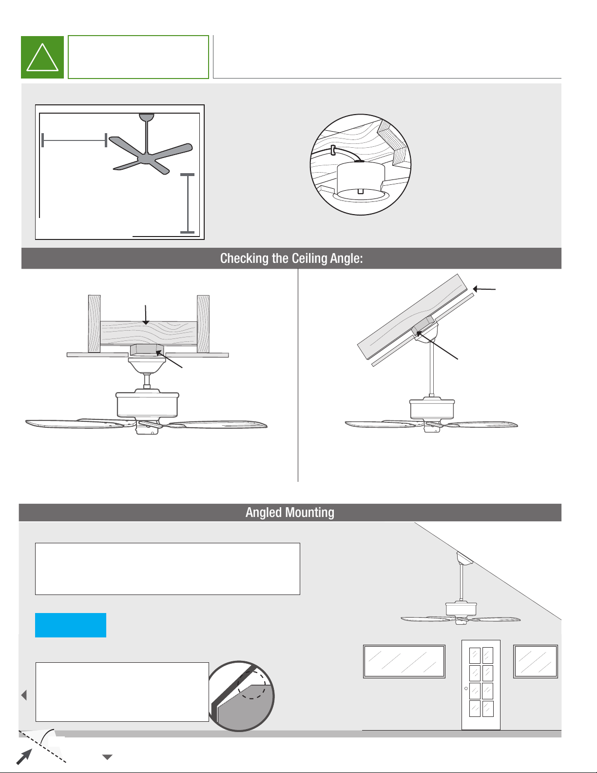
CHOOSE THE RIGHT LOCATION
Check the room dimensions: Check the outlet box:
30 inches
from blade tip to
nearest wall or
obstruction
10 feet
from bottom edge
of blade to the
oor
Standard Mounting
Support Structure
Ceiling Outlet
Box (required)
You must be able to
secure the fan to building
structure or fan-rated
outlet box and clearly
marked acceptable for
fan support of 70 lbs
(31.8 kg) or less.
Support
Structure
Angled Mounting
Ceiling Outlet
Box (required)
If you have a at ceiling:
Hang your fan by a standard downrod. For tall ceilings
you may need a longer downrod.
A little more information on Angled Mounting:
For optimum performance and appearance, a longer downrod should be
used with your Hunter ceiling fan when installing on high or angled ceiling.
Fan can not be mounted on to a
NOTICE
Hunter Pro Tip:
WALL
Determining angle of ceiling:
Fold on the dotted line. Place long edge againts the
wall. Slide towards the ceiling. If the guide touches
the wall but not the ceiling, your ceiling is greater
than 34°.
ceiling with an angle greater than 34°
If you have an angled or vaulted ceiling:
1. You will need a longer downrod.
6
34°
CEILING
Page 7
!
BEFORE YOU BEGIN
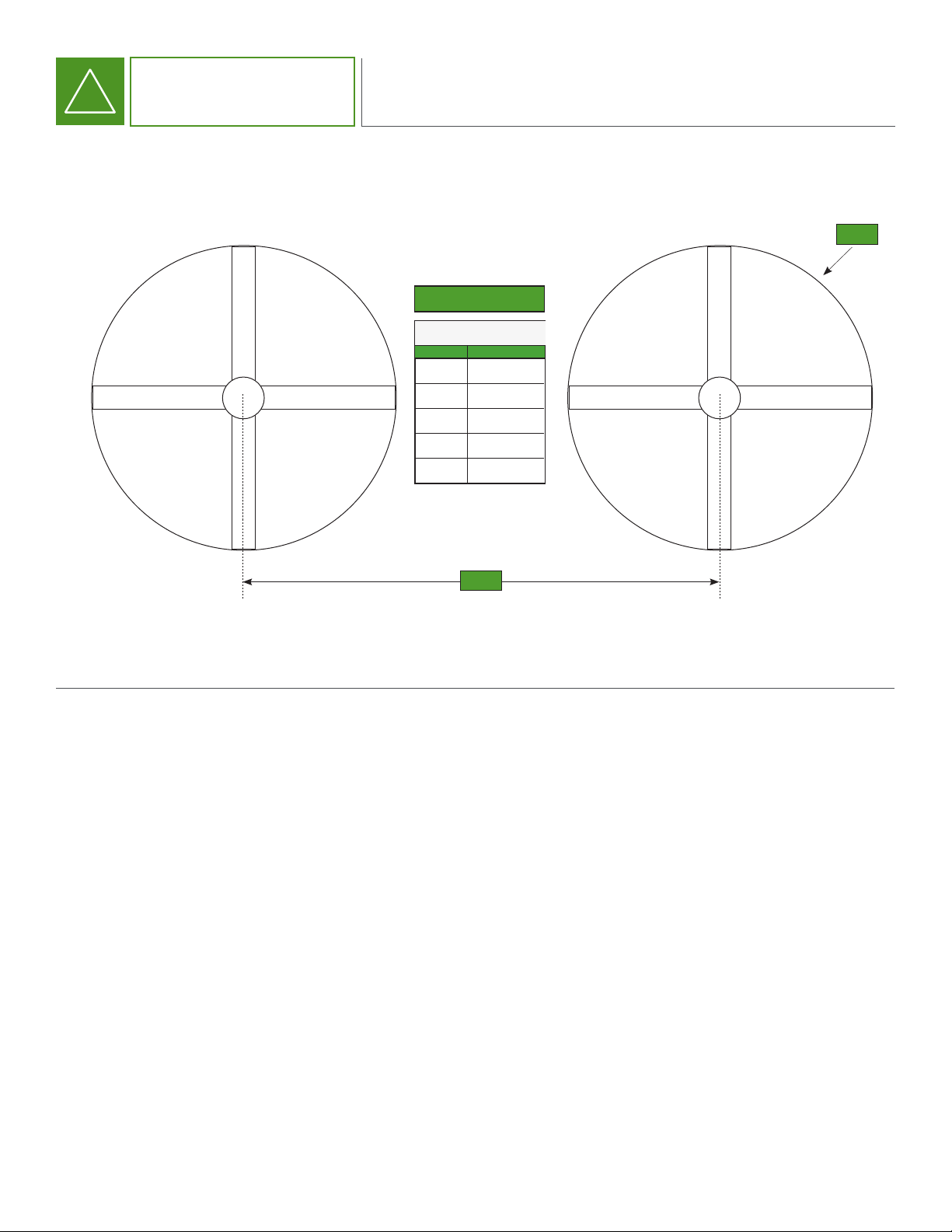
FAN PLACEMENT
FAN PLACEMENT
FAN SPACING CHART
TRAK
A B
MIN - MAXDIA
8ft (96”)
7ft (84”)
6ft (72”)
5ft (60”)
20ft - 32ft
18ft - 28ft
16ft - 24ft
14ft - 20ft
B
A
7
Page 8

!
BEFORE YOU BEGIN
FAN PLACEMENT
ALWAYS mount fan so the bottom edge of blade to the oor is at least 10 feet.
Always mount fans away from the following:
Sprinkler Systems
Prior to installing fans, review all codes applicable to sprinkler systems and fans to ensure code compliance and refer to NFPA 13: Fire
Sprinkler System Installation. In any installation where re sprinklers are present, the fan should not interfere with their operation.
o Fans should be located at least 3 feet below a sprinkler deector.
o Fans should be centered between 4 adjacent sprinklers.
It is your responsibility that the installation complies with the applicable codes. For assistance, please call our Technical Department at 1-844593-FANS (3267).
Walkways and Mezzanines
If the building has elevated walkways or mezzanines, mount the fans so that a person cannot reach the rotating blades in any way. Position
fans so that the tips of the blades are at least 5 feet away from any area where a person may be able to extend outward to reach them.
Lights and Skylights
If possible, avoid mounting fans directly below lights or skylights to avoid any strobe effect caused by moving blades.
There should be a minimum of 2 feet between the blades and any light xture.
Air Discharge Locations
Fans should not be located directly beneath or in line with any air discharge. This includes air conditioning units and evaporative coolers.Such
equipment can be used effectively in conjunction with ceiling fans however the discharge of the unit must be located outside the swept area
of the fan and at a distance of at least two times the diameter.
8
Page 9

!
BEFORE YOU BEGIN
Must be able to
secure the fan to
building structure or
fan-rated outlet box
PRE-INSTALLATION CHECKLIST
The location of the fan will alow for a minumum of 2 feet of blade clearance from
any obstruction and at least 10 feet of clearance above the oor.
If installing multiple fans, reference the fan placement chart for optimal spacing.
The control panel voltage markings (either 100-120VAC or 220-240VAC) should match
your building supply power.
If you are unfamiliar
with wiring, use a
qualied electrician.
30 inches
from blade tip to
nearest wall or
Know your wiring
obstruction
Assess location
10 feet
from bottom
edge of blade
to the oor
Maximum ceiling
angle is 34°.
Assess ceiling angle
Standard Downrod
1
for ceilings 12-14 feet high
Longer Downrod
2
for ceilings 14 feet or higher
Select a downrod length
9
Page 10

!
BEFORE YOU BEGIN
TOOLS NEEDED
Included
1/2”/ M4 Wrench
Ladder
Screwdrivers
x2
Right Angled Screwdriver
Allen Wrench
10
Blade Installation Tool
Page 11

!
BEFORE YOU BEGIN
IN THE BOX
FAN COMPONENTS
G
I
x12
H
x4
E
x2
J
x2
F
K
1 2
E (1) Downrod
F (1) Motor
G (4) Blades
H (1) Ceiling Bracket
I (1) Canopy
J (1) Motor Housing Cover
M
L
K (K1)Data Cable Connector;
(K2) Power Cable Connector
L (1) Remote Control Assembly
M Hanger Bracket Guide
N (1) Installation Manual (not shown)
11
Page 12

INSTALLATION
1
PREPARATION
A
If you have a building
management system you will
need to set the dip switches for
your fan IP address. Use the chart
to set your switches. On is 1. 0 is
the dip switch in the off position.
IP Bit 1 Bit 2 Bit 3 Bit 4 Bit 5
192.168.1.61 0 0 0 0 0
192.168.1.62 0 0 0 0 1
192.168.1.63 0 0 0 1 0
192.168.1.64 0 0 0 1 1
192.168.1.65 0 0 1 0 0
192.168.1.66 0 0 1 0 1
192.168.1.67 0 0 1 1 0
192.168.1.68 0 0 1 1 1
192.168.1.69 0 1 0 0 0
192.168.1.70 0 1 0 0 1
192.168.1.71 0 1 0 1 0
192.168.1.72 0 1 0 1 1
192.168.1.73 0 1 1 0 0
192.168.1.74 0 1 1 0 1
192.168.1.75 0 1 1 1 0
192.168.1.76 0 1 1 1 1
192.168.1.77 1 0 0 0 0
192.168.1.78 1 0 0 0 1
192.168.1.79 1 0 0 1 0
192.168.1.80 1 0 0 1 1
192.168.1.81 1 0 1 0 0
192.168.1.82 1 0 1 0 1
192.168.1.83 1 0 1 1 0
192.168.1.84 1 0 1 1 1
192.168.1.85 1 1 0 0 0
192.168.1.86 1 1 0 0 1
192.168.1.87 1 1 0 1 0
192.168.1.88 1 1 0 1 1
192.168.1.89 1 1 1 0 0
192.168.1.90 1 1 1 0 1
192.168.1.91 1 1 1 1 0
192.168.1.92 1 1 1 1 1
A
F
12
Page 13

INSTALLATION
WARNING
2
CEILING BRACKET
CRUSH HAZARD
To prevent SERIOUS INJURY or DEATH, ALWAYS mount fan directly from building structure or outlet box marked acceptable for fan support
of 70 lbs (31.8 kg).
• CAUTION: Do not install the fan from a single structure such as a purlin, truss, I-beam or bar joist.
• For any questions or concerns regarding the building structure, consult a structural engineer.
A
Remove the four screws
from the restraining bracket
and set aside. Remove the
restraining bracket from
the hanging bracket (H) and
set aside.
Remove any existing bracket prior to installation. Only use the provided Hunter ceiling bracket that came in your fan’s box.
To avoid possible electrical shock, before
installing your fan, disconnect the power by
turning off the circuit breakers to the outlet
box associated with the wall switch location.
Turn Power
A
OFF
Do this rst!
HH
Machine Screws
Use machine screws
(provided with outlet box)
H
and washers when securing
to existing ceiling fan-rated
outlet box. Make sure it is
securely installed and is
acceptable for fan support of
31.8 kg (70 lbs) or less.
MOUNTING TIP
ANGLED
For angled ceilings,
point opening
toward peak.
If you are unable to do this,
call Technical Department at
1-844-593-FANS(3267) for guidance.
13
Page 14

INSTALLATION
WARNING
3
DOWNROD
A
Place the preassembled
downrod (E) through the
canopy(I) and upper motor
housing (J).
A
I
B
Place the bottom of the downrod
into the bracket of the fan while
aligning the holes. Make sure power
cable and communication cable are
facing the power and data ports to
ensure a connection.Place a bolt
through each hole and secure each
bolt with a nut.
E
J
Large End
x2
C
Connect the communication
cable from the downrod to the
fan. Connect the power cable
from the downrod to the fan.
(*240V will have a different
power cable port)
B
I
J
E
D
Attached the secondary hanging
cable to the fan by threading the
cable eye through the upper slot
of the motor shaft. Attach the
D-shackle to the wire as shown and
secure by screwing the pin through
unthreaded wall of shackle and the
cable eye into the threaded wall of
shackle until it is tight.
C
Power Cable
Communication Cable
A
F
D
J
E
Motor Shaft
Upper Slot
F
F
*For 240 V models the power cable
will need to attach to module (A)
14
FAN FALL HAZARD
To prevent SERIOUS INJURY or DEATH, make
sure bolts are securely tightened and shackle
is secure.
Page 15

INSTALLATION
4
CRUSH HAZARD. To prevent serious injury or death, ALWAYS attach the
Retention Cable to the fan motor and secure to the building structure
on EVERY fan.
MOTOR ASSEMBLY
A
Lower the upper motor
housing (J) and twist
clockwise to secure.
Ensure the fan is sealed
by eliminating any gap
between the housing
and fan.
A
F
B
Place hanger guide (M) through the
back of the hanger bracket (H) until
the back of the guide and bracket
are ush. It should snap into place
when correctly installed.
E
J
C
Lift motor assembly and insert hanger
ball into hanger bracket (H), guiding the
hanger ball tabs along the hanger guide
rails until the hanger ball is secure. The
hanger groove should be in between both
hanger ball tabs. REMOVE HANGER
GUIDE FROM BRACKET by squeezing
ends together and sliding away from
bracket.
B
H
D
To secure the motor assembly
take the restraining bracket and
place over the ceiling bracket and
align the holes. Insert and secure a
screw into each hole.
M
C
Hanger
Ball Tabs
Hanger Guide Rails
D
H
H
Hanger Groove
E
H
E
E
15
Page 16

INSTALLATION
5
CRUSH HAZARD. To prevent serious injury or death, ALWAYS attach the
Retention Cable to the fan motor and secure to the building structure
on EVERY fan.
RETENTION SYSTEM
A
Wrap retention cable around
building structure that can
withstand double the installed
fan weight. Use mounting slot in
the canopy to allow the retention
cable to pass out of the canopy
and through the gasket.
B
Secure remaining cable to itself
with cable clamps.
NOTICE
the downrod opening.
A A
Leave approximatlely 3” of slack in
the wire and the cable, at the top of
Dead End
Secure rst clamp on the
loose end of the cable.
Live End
Secure the second clamp to the
cable approximately 6” from
the rst clamp.
H
H
Small End
I
NOTICE
Retention Cable. If done incorrectly, the U-bolt could crush the wire when tightened and can reduce the strength of the wire.
When attaching cable clamps, remember: “Never saddle a dead horse.”
Place the u-bolt on the “dead” end of the Retention Cable and the saddle on the “live” portion of the
I
16
Page 17

INSTALLATION
6
WIRING
Electric Shock Hazard
Electric Shock Hazard.
To prevent serious injury or death:
• BEFORE installing or servicing your fan, ALWAYS disconnect the power by turning off the circuit
breaker or breakers to the fan locations and conrm Lockout/Tagout procedures are in place.
• If you cannot lock the circuit breakers in the off position, securely fasten a prominent warning
device, such as a tag, to the electrical panel.
• All wiring must be in accordance with national and local electrical codes, including ANSI/NFPA
70. If you are unfamiliar with wiring or in doubt, consult a qualied electrician.
A
Fully unscrew data connector and remove the gasket from either
end. Slide data connector end over data cable. Slip gasket onto
data cable text side out and insert gasket into data connector end.
Push gasket until it is ush with data connector end. Slip data
connector housing over data cable. Plug data cable into center
connector and thread data connector housing onto data connector
center by twisting clockwise until tight. Thread data connector end
onto data connector housing by twisting clockwise until tight and
gasket seals the cable. Repeat for the other end.
Data Connector
Housing
A
Data Connector
End
K1
Gasket
B
Fully unscrew power connector. Place power cable and canopy ground wire through power connector
end. Next, slide male power connector housing over wires. Using a small phillips head screw driver,
back off screws on one half of wire terminal. The ridged side of the power cable is the neutral and goes
into the hole marked (N). The center wire from the power cable is ground. Twist together with ground
wire from canopy and insert into hole with ground symbol ( ). The outer wire without ridges is the
Live (L) and goes into the hole marked (L). Tighten down all terminal screws securely to make wire
connections. Repeat for wires from ceiling with female power connector housing and the other power
connector end. To secure the power connector, tighten male to female and then the connector ends by
twisting clockwise. (all sections of the power connector)
Data Connector
Center
Data Cable
Data Connector
Housing
Data Cable Sealed
Data Connector
End
Gasket
B
Canopy
Ground Wire
K2
Power Connector
End
Ridged
Side
Downrod Wiring Ceiling Wiring
Male Power
Connector Housing
N
L
Power Connector
Center Wiring Engaged
Power
Connector Center
Female Power
Connector Housing
N
L
Power Cable Sealed
Power Connector
End
K
17
Page 18

INSTALLATION
7
A
Position data connector, power connector, and excess wiring inside
the ceiling bracket. Lift the canopy and align the single ridge on the
canopy with the single ridge on the ceiling gasket. Twist clockwise
to secure. The singe ridge of the canopy will align with the two
ridges of the ceiling gasket.
A
MOUNTING
H
I
H
I
J
E
18
Page 19

INSTALLATION
8
BLADES
A
Match blade with colored circle to blade iron with the
same colored circle. Slide blade over blade iron and
align the blade screw holes with the blade iron holes.
Place blade installation tool into hole closest to the
fan to help align screw holes.
A
G
F
B
Insert a screw into the remaining two
screw holes. Tighten both screws
G
C
Remove installation tool and insert a
screw into the remaining screw hole
and tighten. Repeat for each blade.
F
B
C
Repeat x4
F
G
NOTICE
personal injury, do not bend the blades or blade holders when installing the fan.
ALWAYS conrm the colors on each fan blade holder matches the colors on the blade. This will ensure
that the fan is properly balanced to prevent possible damage due to wobble. To reduce the risk of
19
Page 20

INSTALLATION
9
REMOTE CONTROL
A
To access the battery compartment, remove the
small Phillips head screw that secures the battery
door to the transmitter assembly. The battery should
be installed with the positive (+) side up. Replace
with a CR2032 battery when necessary.
The remote transmitter is already paired to the
receiver and ready to use.
Note: If you would like to operate multiple fans or
multiple remotes, or if your remote is not working,
please see the Troubleshooting section at the end of
this manual.
A
Battery
Door
Press = Fan Off
Single Press = Set Fan to Speed 1
Press Twice= Set Fan to Speed 2
Single Press = Set Fan to Speed 3
Press Twice = Set Fan to Speed 4
Single Press = Set Fan to Speed 5
Press Twice = Set Fan to Speed 6
Single Press = Set Fan to Speed 7
Press Twice = Set Fan to Speed 8
Single Press = Incremental Light Output 10%
Long Press = Light On Output 100%
Single Press = Decremental Light Output 10%
Long Press = Light Off
Slide Up = Updraft
Slide Down = Downdraft
Phillips
Head
Screw
B
Your remote comes with three mounting options.
B.1
Option one is a wall
plate that has two posts
on which to mount your
remote transmitter
when not in use.
B.2
Option two and three use an extended wall plate
that replaces your pre-existing light switch plate.
Option two combines the extended wall plate with
an additional plate that has two posts on which to
mount your remote transmitter when not in use.
Install the extended wall plate. Then install the
x2 x2
secondary plate to the extended wall plate.
NOTICE
Toggle dimming mode by holding OFF ( ) and quickly press
Light Down ( ) two times
B.3
Option three adds two cradle arms overtop
of the remote transmitter onto the extended
x2
wall plate. This locks the remote transmitter
into place so that it can only be removed by
removing the two cradle arms.
x4
x2
20
Page 21

REFERENCE
MAINTENANCE
Electric Shock Hazard
Electric Shock Hazard
To prevent serious injury or death:
• BEFORE performing maintenance or service, ALWAYS disconnect the power by turning off the circuit
breaker or breakers to the fan locations and conrm Lockout/Tagout procedures are in place.
• If you cannot lock the circuit breakers in the off position, securely fasten a prominent warning device,
such as a tag, to the electrical panel.
• Do not remove covers while power is on.
Blade Cleaning
Depending on the commercial application, dust or other particulates can build up on the fan blades over time. At
least every 12 months, a maintenance person or skilled trade professional should clean the blades using a rag or
sponge and hot water or regular cleaning solutions.
DO NOT use chlorine or any chemicals containing chlorine as they may cause damaged to the blades.
Retention System Check
Each fan is installed with a retention system. Every 12 months, check that the Retention Cable is properly attached
to the building structure. Inspect the visible portions of the Retention Cable for damage, including fraying.
The Retention Cable is an important part of the safety system and protects users in the
unlikely event of a catastrophic situation. It is critical for fan owners to ensure that it is intact and properly secured.
Replacement Parts
Please call 1-844-593-FANS (3267) for replacement parts.
Service
If the fan does not operate properly using the procedures in this manual, follow Lockout/Tagout procedures for your
facility and lockout all power to the unit and contact our Technical Department for further assistance at 1-844-593FANS (3267).
21
Page 22

REFERENCE
TROUBLESHOOTING
Symptom
FAN WILL NOT START
MOTOR IS PULLING
EXESSIVELY HIGH AMPS
FAN IS “SWINGING” AS IT
RUNS
A FAN BLADE APPEARS TO
BE ‘SAGGING’
Possible solution
• Verify that the fan’s circuit breaker has power and that it is on.
• Check for secured plug connections. Each connection should be checked to
ensure they are fully engaged.
• Inspect for loose wiring connections. Each termination should be checked
to be sure they are rmly tightened.
• Make sure the motor voltage is a match for the supply voltage.
• Check for correct fan blade installation. Be sure that all blades have been
properly installed according to color and are tightened.
• Ensure all downrod hardware has been tightened.
• Check for improper incoming air discharge. Make sure that no discharge is
blowing directly on the fan.
• Make sure that the ‘sagging’ blade has been properly tightened.
TO PAIR A REMOTE TO
A FAN(S):
TO UNPAIR A REMOTE
FROM A FAN(S):
TO TOGGLE DIMMING MODE:
• Turn OFF Power to Fan for at least 5sec, and then restore Power. Hold down
both the “Fan OFF” and “ ” button at the same time. The remote LED will
ash after several seconds. Fan will emit audible “BEEP” to conrm the
operation.
1. Power Cycle the Fan
2. Long hold on both button and DOWN. You will see LED is on.
3. Wait until the LED is off
4. While still pressing button , release button DOWN.
5. Keep pressing button and have a short press on the button DOWN.
6. You will see LED blinks 5 times for command sent conrmation. Release
button .
1. Long hold on both button OFF and DOWN. You will see LED is on.
2. Wait until the LED is off
3. While still pressing Power button, release button DOWN.
4. Keep pressing button OFF and have a short press on the button DOWN.
5. You will see LED blink once for command sent conrmation. Release the
power button.
For situations beyond the scope of this Guide,
please call our Technical Service Department at
22
1-844-593-3267 (FANS).
180 Threet Industrial Road
Suite 120, Smyrna, TN 37167
HUNTERFAN.COM
©2020 Hunter Fan Company. All rights reserved.
MI001-01 020620
 Loading...