

Page 1
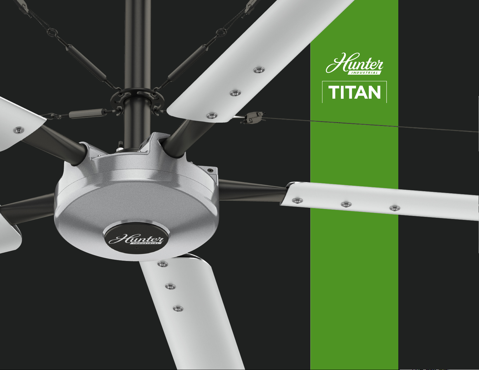
INSTALLATION MANUAL
Page 2

The Hunter legacy is not only about
quality—it’s about longevity. We invented
the ceiling fan. We build fans that last, fans
that are designed as fans. We design our
fans while considering each person in the
process—from the installer to the owner.
CONTENTS
BEFORE YOU BEGIN
!
SAFETY & PRECAUTIONS 2-3
FAN PLACEMENT 4
MAINTENANCE 5
IN THE BOX 6
TOOLS NEEDED 7
INSTALLATION
STEP 1: MOUNTING 8
STEP 2: MOTOR ASSEMBLY 9
STEP 3: RETENTION SYSTEM 10
STEP 4: CONTROL PANEL 11
STEP 5: TOUCHSCREEN 12
STEP 6: GUY WIRES 13
STEP 7: BLADES 14
TOUCHSCREEN
LEGACY
1886
TOUCHSCREEN TYPES 15-16
HOME SCREEN 17
FAN SCREEN 18
REFERENCE
ELECTRICAL 19
TOUCHSCREEN TEMPLATE 20
CONTROL PANEL 21
TROUBLESHOOTING 22
AUTHENTICITY
In a world full of impersonators, be an
original. We invented the ceiling fan,
and we stand behind our products.
Page 3
!
BEFORE YOU BEGIN
SAFETY & PRECAUTIONS
READ THE ENTIRE MANUAL BEFORE OPERATING THE FAN
Read and understand this manual before installing or operating a fan unit. Installation, adjustment, repair or maintenance must be performed by qualied personnel.
Follow all safety practices and instructions during the installation, operation and servicing of the fan. Failure to apply these safety practices could result in death or serious
injury. If you do not understand the instructions, please call our Technical Department for guidance. Technical Department contact information can be found on page 22.
All fan controls and incoming power should be installed only by qualied technicians familiar with the requirements of the National Electrical Code and local codes.
Failure to follow these guidelines will void the manufacturer’s warranty. All electrical controls are congured at the factory and are ready to use. No user adjustments are
available. Follow the included installation instructions when installing this device to ensure proper operation. Do not make any changes to any part of the fan without rst
consulting Hunter Industrial Fan. Installation is to be in accordance with the National Electrical Code, ANSI/NFPA 70-1999 and local codes.
WARNING! Be aware of electric shock hazard, explosion, or arc ash
The user is responsible for compliance with all international and National Electrical Code requirements with respect to grounding of all equipment. Many of the parts of
this unit operate at line voltage. DO NOT TOUCH. Install all covers before applying power or starting and stopping the unit. To reduce the risk of electric shock or injury,
use this unit only in the manner intended by the manufacturer. If you have questions, call our Technical Department at 1-844-593-FANS (3267).
Before servicing or cleaning the unit, switch power off at the service panel and lock the service disconnecting means to prevent power from being switched on
accidentally. When the service disconnecting means cannot be locked, securely fasten a prominent warning sign, such as a tag, to the service panel. At all times, leave
the power off at the service panel. To reduce the risk of electric shock or injury, use this unit only in the manner intended by the manufacturer. If you have questions,
call our Technical Department at 1-844-593-FANS (3267).
DAMAGED EQUIPMENT
Do not operate or install any fans or fan accessories that appear to be damaged. Failure to follow this instruction can result in death, serious injury, or equipment damage.
SERVICE
If the fan does not operate properly using the procedures in this manual, remove all power to the unit and contact our Technical Department for further assistance at
1-844-593-FANS (3267). Keep all body parts clear of moving parts at all times. All electrical troubleshooting and repair must be done by a qualied technician and meet
all applicable codes.
2
Page 4

!
BEFORE YOU BEGIN
KEY RETENTION SYSTEM COMPONENTS
Our fans are engineered with key features to prevent pieces of the fan from falling in the unlikely event of a catastrophic failure. Used together, these systems provide
comprehensive protection of people, equipment and property.
Install the retention cable on EVERY fan. The retention cable, if installed per Hunter Industrial Fan specications, will prevent the fan from falling in the unlikely event
that the mounting system should fail.
SAFETY & PRECAUTIONS
CAUTION!
The fan should never be run without a properly installed retention cable, which is supplied with every fan along with all required hardware.
If the retention cable is not installed, the warranty will be voided.
MARK THE FLOOR TO ALERT PERSONNEL
When mounting a fan in an area where materials may be elevated into its path, we recommend marking or painting the oor with a large crosshatched circle to alert
personnel of the overhead location of fans.
WEIGHT CONSIDERATIONS
We recommend that a building structure be capable of holding approximately twice the stated hanging weight of the fan.
The maximum hanging weight for the 24-foot fan is 204 lbs., adding the weight of an additional drop length.
If there is any uncertainty in the strength of the building structure, a professional structural engineer should perform a thorough evaluation of the building prior to
purchasing the fans. Hunter Fan provides guidelines for mounting fans; however, it is the sole responsibility of the building owner and installer to ensure the safety of the
mounting system, that the building structure is sound, and that the installation complies with all federal, state, and local codes.
CHECK FEDERAL, STATE, AND LOCAL CODES
Check all relevant codes to make sure that all product certications, product listings, and building regulations are met.
Code compliance is the responsibility of the installer.
WINDY CONDITIONS
Fans should not be operated in windy conditions. Fans should not be installed in locations where it is frequently windy.
3
Page 5
!
BEFORE YOU BEGIN
FAN PLACEMENT
SPRINKLER SYSTEMS AND FAN PLACEMENT
In any installation where re sprinklers are in place, the fan should
not interfere with their correct operation. Fans should be located
no less than 3 feet below a sprinkler, and placed central to each
sprinkler quadrant. Our industrial control panel can be connected
to a re relay system, which, in an emergency, will stop fans in case
of re.
Prior to installing fans, review all codes applicable to sprinkler
systems and fans to ensure code compliance and refer to NFPA 13
Standard from the National Fire Prevention Association.
Please call our Technical Department for guidance at 1-844-593-FANS
(3267). However, it is your sole responsibility to see that the
installation is completed to code and that it is correct.
OTHER INFORMATION ON PLACEMENT AND SPACING
If possible, avoid mounting fans directly below lights or skylights to
avoid any strobe effect caused by moving airfoils. Note, a large fan,
20 to 24 feet in diameter, performs best at 20 to 30 feet above the
oor, but acceptable performance has been demonstrated as low as
10 feet and as high as 50 feet.
If the building has a mezzanine, fans should be mounted so a
person cannot reach a fan in any way from the upper level/deck.
Make certain that fans are positioned so that the airfoil tips are at
least 3 feet away from any area where a person may be able to
extend outward to reach them.
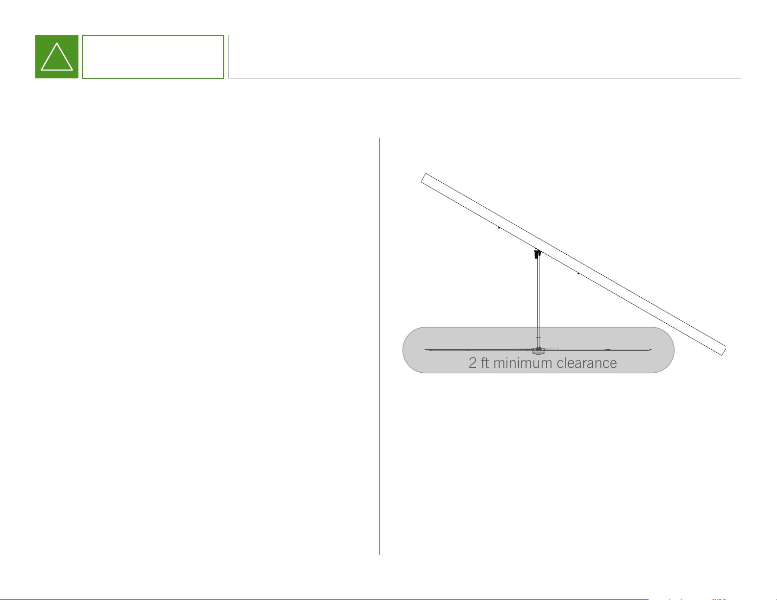
ROOF PITCH
2 ft minimum clearance
Fans should not be located directly beneath any air discharge.
This includes air conditioning units and evaporative coolers. Such
equipment can be used effectively in conjunction with HVLS fans
but the discharge must be located outside of the swept area of
the fan.
4
Page 6

!
BEFORE YOU BEGIN
GUY WIRE CHECK
Checking a fan’s guy wires for tension and inspecting for frayed sections could prevent a problem before it occurs. Fan owners should conrm that the guy wires are not
wrapped around any sharp edges. We recommend attaching guy wires to the building with provided clamps to prevent fraying. Turnbuckles should be checked to ensure
tightness. If they are loose, the guy wire cables need to be re-tensioned.
AIRFOIL CLEANING
Depending on the commercial application of the fan, there can be quite a bit of dust or other particulates that cling to the fan’s airfoils. While this may not affect fan performance, we recommend fan owners keep airfoils clean by having a maintenance person or skilled trade professional–who has experience using a lift–wipe the fan airfoils with
a rag or sponge using hot water or regular cleaning solutions. Please do not use chlorine or any chemicals containing chlorine.
RETENTION SYSTEM CHECK
Each fan is installed with a retention system. The retention cable is attached to the motor and wraps around the building structure. The safety cable is an important part of
the safety system and protects users from if a catastrophic event occurs. It is critical for fan owners to ensure that it is intact and properly secured.
REPLACEMENT PARTS
MAINTENANCE
Please call our Technical Department at (844) 593-3267.
5
Page 7
!
BEFORE YOU BEGIN
IN THE BOX
FAN COMPONENTS
a)
f)
b)
d) e)
c)
TITAN
MOUNTING HARDWARE KIT
a)
c)
b)
COMMUNICATON KIT
a)
b)
GUY WIRE KIT
a)
b)
c)
FAN COMPONENTS
a) (1) Downrod
b) (1) Motor & (5) Motor Nuts
c) (1) ICP (industrial Control Panel)
d) (1) Touchscreen
e) (1) Installation Manual
f) (5) Blades
MOUNTING HARDWARE KIT
a) (2) Shims
b) (2) Clamps
c) (4) Bolts, Washers, Nuts
GUY WIRE KIT
a) (1) Gripple kit
b) (4) Beam Clamps
c) (4) Turnbuckles
COMMUNICATION KIT
a) (1) 100 ft Terminated Cat5 Cable
b) (2) RJ45 Connectors
6
Page 8
!
BEFORE YOU BEGIN
TOOLS NEEDED
Metric Ratcheting Wrench Set
Metric (Deep & Short) Socket and Ratchet Set
Metric Allen Wrench Set
Metric Allen Socket Set
Tape Measure
Magnetic Level
Torque Wrench
Wire Rope Cutters
Phillips and Flat Head Screwdrivers
#10 to #14 AWG Strippers
Multimeter
Cat5 Termination Tools (optional)
7
Page 9

INSTALLATION
1
MOUNTING
A
Secure bracket and downrod to lift
and raise to I-beam.
B
Assemble the mount with shims
and clamps on bracket. Hook the
clamp on one side of the I-beam and
tighten hardware until the mount is
snug but can still be moved.
C
Assemble the opposing shim
and clamp on to the I-beam and
hand tighten.
D
Center the mount under the I-beam.
Ensure the clamps have maximum
engagement on both sides and
tighten hardware.
A
D
B
BOLTS
WASHERS
CLAMPS
SHIMS
C
NUTS
8
Page 10

INSTALLATION
A
Insert clevis pin into retention rod
and secure with clip provided.
B
Join the two connectors and twist,
making sure they lock together.
C
Lift motor assembly (see tip) while
pushing cables into downrod. Feed
the press studs through downrod
ange. Avoid pinching cable
between motor ange and downrod
ange and secure with nylon lock
nuts. Pull excess wire and cable
through top of downrod.
2
MOTOR ASSEMBLY
A B
C
TIP
Use packaging to
transport motor
onto lift equipment.
Raise lift to install
motor to downrod.
9
Page 11

INSTALLATION
A
Wrap retention cable around
beam or building structure.
B
Secure remaining cable to itself
with cable clamps. Coil excess
cable and secure.
3
RETENTION SYSTEM
A B
10
Page 12

INSTALLATION
4
CONTROL PANEL
A
Position panel with plug connectors
facing down. Mount control panel
with fasteners, one in each corner
of the panel.
B
Connect VFD cable from fan to
control panel. Twist connector to
lock in place. Secure excess cable to
ceiling or beam.
C
Connect the communication
cable to one of the comm terminals
and run down to user touchscreen
location.
A B
C
D
TIP
For detailed
control panel wiring
diagram see
Page 21
NOTE
Twist Lock will act
as a disconnect.
D
Connect electrical plug to panel.
Twist connector to lock into place.
CAUTION: DO NOT CONNECT POWER
UNTIL MECHANICAL INSTALLATION
IS COMPLETE.
11
WARNING!
Before completing the mechanical installation, ensure breaker is off and all Lockout/Tagout procedures are
in place. The electrical receptacle for the panel should be installed prior to panel installation. For a chart of
receptacles, refer to page 19.
If the retention cable is not installed, the warranty will be voided.
Page 13

INSTALLATION
5
TOUCHSCREEN
A
Mount touchscreen enclosure
to wall.
B
Connect communication cable
from control panel to the
COMM 1 port at base of
touchscreen unit.
C
Connect pre-wired 110 plug to
input power receptacle.
D
Attach screen panel to enclosure
using screws in each corner.
A
COMM 1 COMM 2
B
TIP
Use Mounting
Template on
Page 20
D
INPUT
POWER
C
NOTE
For more information on operating the
Touchscreen, refer to Page 15
110 PLUGRJ45
12
Page 14

INSTALLATION
A
Attach guy wire to building structure
with provided beam clamps while
maintaining a 45-degree angle
between the ceiling and the guy wire.
DO NOT WRAP GUY WIRES
AROUND THE BUILDING STRUCTURE.
B
Hook end of turnbuckle to
the guy wire disc located on
the downrod.
6
GUY WIRES
A
C
GUY WIRE DISC
C
Attach guy wire to closed
turnbuckle end with provided
gripple (refer to direction on
gripple package).
D
B
D
Place level against the downrod
and tighten the turnbuckles by
hand in a crisscross pattern.
Periodically check to make sure
fan is level. Tighten set screws.
13
Page 15

INSTALLATION
A
Line up the pin on the post with
the opening on the blade holder.
B
Using our quick connect system,
insert the blade tube into the
blade hub. The blade will click into
place at the correct pre-set angle.
C
Use a torque wrench to tighten
the two set screws to 20 ft. lbs.
7
BLADES
A
(240 lbs.)
D
Repeat steps A-C for each of the
four remaining blades.
B
14
Page 16

TOUCHSCREEN
STARTUP SCREEN
TOUCHSCREEN TYPES
HOME SCREEN
15
Page 17

TOUCHSCREEN
FAN SCREEN
TOUCHSCREEN TYPES
CONFIGURATION
SCREEN
16
Page 18

TOUCHSCREEN
Date and time display
Arrows take you to individual fan screens and display the speed and direction of each fan. Speed is indicated by
the lit green bars, while airow direction is shown by the up or down placement of the arrows.
Powers all fans on and off.
HOME SCREEN
Settings button will take
you to the version screen.
Congure button takes you to
individual fan input screens.
17
Takes you back to
main screen.
Page 19

TOUCHSCREEN
Press to turn individual fan on or off. When button is green,
fan is on. When button is gray, fan is off.
Press to set downward airow direction.
Press to set upward airow direction.
FAN SCREEN
Press “+” to increase fan speed, “-” to reduce.
Use “+” and “-” as toggle to congure multiple fans.
Congure button takes you to
the current fan input screen.
Takes you back to
main screen.
NOTE
For all buttons, “green” indicates
an “ON” status
18
Page 20

REFERENCE
ELECTRICAL
19
Page 21

REFERENCE
TOUCHSCREEN TEMPLATE
5.51 in
(140 mm)
5.51 in
(140 mm)
20
Page 22

REFERENCE
1-844-593-FANS HunterIndustrialFan.com
FOR REFERENCE ONLY
CONTROL PANEL
TO FAN
COMM 1
AC POWER IN
COMM 2
Titan
INPUT
9-40 VDC
E-STOP
+
-
21
NO
NC
Page 23

REFERENCE
TROUBLESHOOTING
FAN WILL NOT START
TOUCHSCREEN IS BLANK
FAULT SCREEN ON UI?
Check to see if all plugs are securely connected.
Verify the touchscreen has power.
Conrm supply power is adequate and functional.
Verify UI has power.
For fault codes, please call our
Technical Department at (844) 593-3267.
22
Page 24

2434 ATRIUM WAY
NASHVILLE, TN 37214
1-844-591-3267
TECHNICAL DEPARTMENT: 1-844-593-FANS (3267)
HUNTERINDUSTRIALFAN.COM
©2016 Hunter Fan Company. All rights reser ved. | REV A.
 Loading...