

Page 1
CAUTION:
1. Read entire instructions carefully before beginning installation.
2. To avoid possible electrical shock, be certain electricity is
shut off at main panel before wiring.
3. All wiring must be in accordance with national and local
electrical codes. If you are unfamiliar with wiring, you should
use a qualified electrician.
4. To reduce the risk of personal injury, install the fan only to
the building structure according to these instructions, and use
only the hardware supplied.
WARNING:
1. To reduce the risk of fire or electrical shock, do not use a solid
state speed control with this fan. Use Hunter Controls only.
2. To reduce the risk of personal injury, do not bend the blade
brackets when installing the brackets or cleaning the fan. Do
not insert foreign objects in between rotating fan blades.
Step 1: Pre-Installation Instructions
A.
Select installation site. Check to see that in normal use no
object can come in contact with the rotating fan blades. The
mounting site should also meet the precautions listed in Step 3
below.
B. Installation hardware is included for a standard drywall or
plaster ceiling. You will need a 4" x 1-1/2" or a 4" x 1/2" outlet
box and wire nuts (2) which can be purchased from any hardware store or electrical supply house.
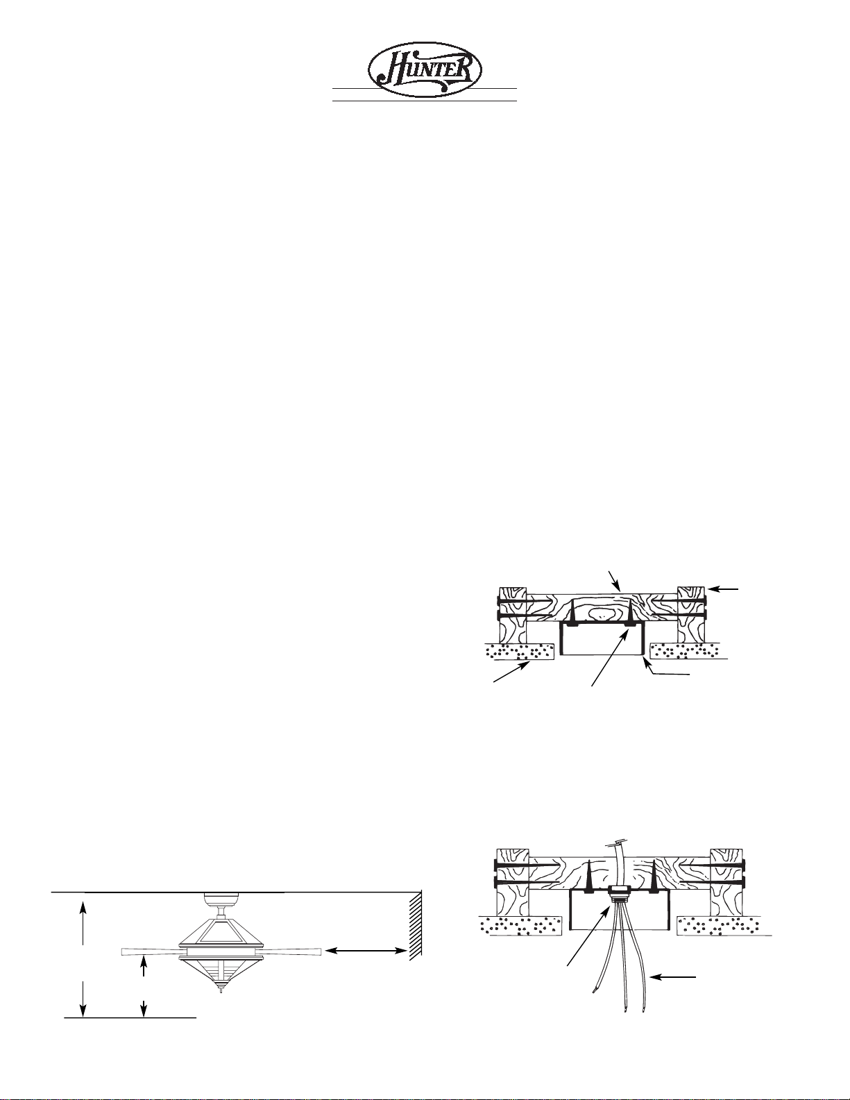
C. The fan blades must be mounted at least 7' above the floor.
For maximum efficiency, they should not have any obstruction
(walls, posts, etc.) within 24" of the blade tips. See Figure 1 for
mounting distances.
Step 2: Inspection of Fan
A.
Unpack the fan carefully to avoid any damage to the components.
B. Check for any shipping damage to the motor and the fan
blades. If more than one fan is being installed, keep the matched
and balanced fan blades in sets, as they were shipped. Should
one of the fan blades become damaged during shipment, return
all blades in the set for replacement.
C. Check contents to be certain it contains a bag of parts.
Step 3: Installation of Outlet Box and
Rough-In Wiring
CAUTION: Your Hunter ceiling fan with accessories can weigh
up to 35 lbs. The following precautions must be taken for safety
and to ensure that your fan is securely mounted to the ceiling.
¥ Be certain electricity is ÒoffÓ at fuse panel when inspecting or
repairing installation site.
¥ All wiring must meet local and national electrical codes.
¥ Do not mount directly to an unsupported ceiling or to an elec-
trical outlet box. Mounting must support a 35 lb. fan with
accessories.
A. Secure metallic outlet box 4" x 1-1/2" or 4" x 1/2" deep to
2 x 4 cross brace between two ceiling joists as shown in Figure 2.
The outlet box must be recessed into the ceiling by 1/16" minimum. Secure the outlet box to the cross brace by drilling (2)
pilot holes no larger than the minor diameter of the wood screws
(5/64") and use two #8 x 1-1/2" wood screws and washers. Use
the innermost holes for securing the box. Orient the box so the
outermost holes will be used in Step 4B.
CAUTION: Do not use a lubricant on screws.
B. Bring electrical cable into the outlet box and attach with an
approved connector. Make certain that wiring meets all national
and local electrical codes. Wire leads should extend at least 6"
beyond outlet box for ease in making connections. See Figure 3.
41225-01 10/95 - 1 - ©1995 HUNTER FANCO.™
INSTALLATION INSTRUCTIONS
FOR HUNTER CEILING FAN TYPE 2
READ AND SAVE THESE INSTRUCTIONS
SINCE 1 8 8 6
FIGURE 2. Outlet Box
Figure 1. Wall Clearances
2 X 4 BRACE
CEILING
OUTLET BOX
CEILING
JOIST
#8 WOOD SCREW & WASHER
FIGURE 3. Wiring Outlet Box
CONNECTOR
6" MIN.
LEAD
LENGTH
8' MIN.
CEILING
TO FLOOR
7' MIN.
TO FLOOR
24"
CLEARANCE TO
OBSTRUCTIONS
®
Page 2
Step 4A. Assemble Top Housing
CAUTION: Do not lift motor by wires.
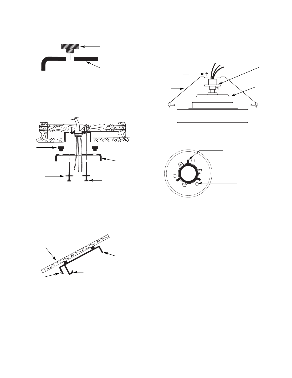
A. Assemble the housing to the hanger adapter using (3) #8-32
screws. See Figures 4C and 4D. First align the (3) raised tabs of
the hanger adaptor with the (3) narrow notches in the housing.
Make certain the housing sits flat on top of the adaptor. Tighten
the screws securely.
NOTE: Assembly Methods For
InstallerÕs Choice Hanging System
Your new Hunter fan can be hung in (2) different manners. (1) as
a low profile fan or (2) as a ball type hanging fan. Please read
Steps 5 through 7 and decide which style mounting to use.
Step 4: Installation of Ceiling Plate
A.
Install the (3) rubber bushings into the top of the ceiling
plate by inserting small side of the rubber bushing into the three
holes in the ceiling plate. See Figure 4.
B. Insert the lead wires through the opening in the ceiling plate
and install the ceiling plate to the 2 x 4 brace which supports the
outlet box. Use (2) #10 wood screws 3" long and (2) flat washers
for mounting. Drill (2) pilot holes for the mounting screws 9/64"
diameter. See Figure 4A.
NOTE: When mounting the fan on a vaulted ceiling, make sure
that one set of elongated slots in the ceiling plate is aligned vertically with the ceiling joist, or horizontally with the cross brace if
a cross brace is used. Be sure one of the threaded screw holes in
the side of the ceiling plate is facing down. See Figure 4B. The
hook in the ceiling plate should be in the down position.
NOTE: When attaching ceiling plate to the outlet box support,
make certain bushings remain in place.
NOTE: Tighten the ceiling plate mounting screws only enough to
provide slight compression of the bushings. Do not overtighten.
41225-01 10/95 - 2 - ©1995 HUNTER FANCO.™
FIGURE 4. Rubber Bushings
FIGURE 4C. Assemble Housing
RUBBER
BUSHING
CEILING
PLATE
FIGURE 4A. Installing Ceiling Plate
RUBBER
BUSHING
CEILING
PLATE
FLAT
WASH-
3" WOOD SCREW
VIEW: LOOKING DOWN ON TOP OF FAN
SHOWING TAB AND NOTCH ALIGNMENT
FIGURE 4D. Assembling Housing
ALIGN RAISED TABS
ON ADAPTOR WITH
NARROW NOTCHES ON
TOP HOUSING
ASSEMBLY
SCREW
LOCATIONS
CEILING
PLATE
HOOK
SCREW HOLE
VAULTED
CEILING
Figure 4B. Vaulted Ceiling
HANGER
ADAPTOR
MOTOR
HOUSING
#8-32
Page 3
Step 5-1: Fan Assembly, Low Profile Version
A.
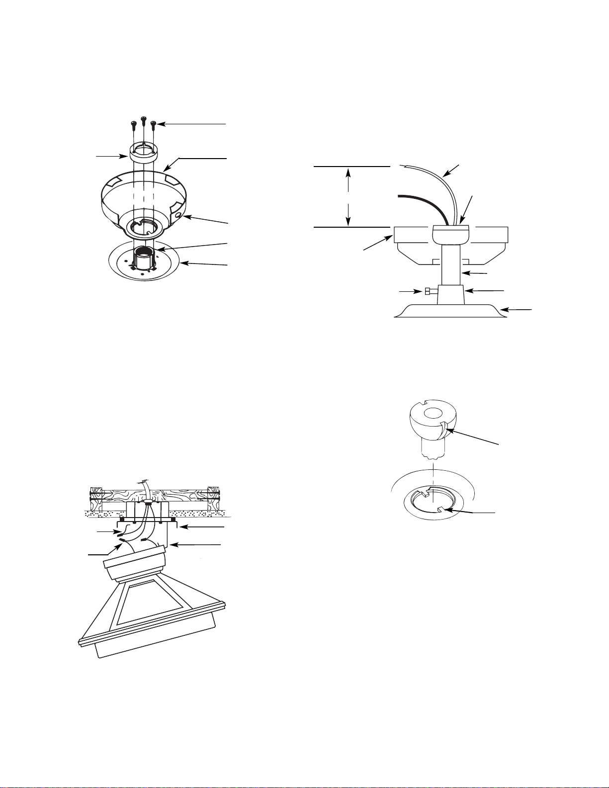
Place the canopy on top of the fan so the hole in the bottom
of the canopy fits over the adaptor on the top of the fan. See
Figure 5. Place the canopy assembly washer inside the canopy
with the vertical flange of the washer resting on the inside of
the canopy.
B. Position the (3) slots in the canopy assembly washer over
the (3) threaded holes in the adaptor. see Figure 5.
C. Secure the canopy to the top of the fan using the (3) #8-32
x 7/8 long screws with lock washers. Make certain all screws
ae tight. Failure to do so could result in the fan falling.
CAUTION: To ensure proper engagement of the canopy
assembly screws, the canopy must fit snug against the top of
the fan.
CAUTION: Do not lift motor by wires.
D. Being careful not to scratch the canopy finish, hang the fan
from the hook in the ceiling plate using the round hole in the
top of the canopy. See Figures 5 and 5A.
Step 5-2: Ball Hanging Version
CAUTION: Do not lift motor by wires.
A. Insert the pipe nipple through the canopy and feed the wires
from the fan through the pipe nipple. Screw the pipe nipple into
the fan adaptor until it is tight (at least 4-1/2 turns). Tighten the
pipe nipple setscrew very securely, locking the pipe nipple to the
fan adaptor. See Figure 5B.
CAUTION: Failure to securely tighten the fan adaptor setscrew
could result in the fan falling.
B. Before hanging the fan from the ceiling plate align and
engage the (2) tabs in the bottom of the canopy with the (2)
grooves in the hanger ball. See Figure 5C.
Using the round hole in the top of the canopy, hang the fan from
the hook in the ceiling plate. Make sure both tabs in the canopy
remain engaged with the grooves in the ball. Be careful to not
scratch the finish while hanging the fan. See Figure 5A.
Step 6: Final Wiring
A.
Connect electrical supply leads from the motor, using
approved connectors. Connect the black electrical supply lead to
the black motor lead and the black with white stripe motor lead
(see note). Connect the white electrical supply lead to the white
motor lead. Connect the ground wire to the green leads from the
pipe nipple and ceiling plate. See Figure 5A.
NOTE: If a separate wall switch will be used to control the light
fixture, connect the black wire with white stripe to the wall
switch lead. The wall switch must be acceptable for use as a general use switch.
41225-01 10/95 - 3 - ©1995 HUNTER FANCO.™
Figure 5. Low Profile Version
Figure 5B
ASSEMBLY
WASHER
#8-32 SCREW
CANOPY
ROUND HOLE
LEAD WIRES
PIPE NIPPLE BALL
PIPE NIPPLE
FAN ADAPTOR
MOTOR
PIPE NIPPLE
SETSCREW
CANOPY
ADAPTOR
TOP OF FAN
Figure 5A. Hanging the Fan
GREEN
GROUND
CONNECTOR
CEILING PLATE
HOOK
Figure 5C. Aligning Tab & Groove
GROOVE IN
HANGER BALL
TAB IN BOTTOM
OF CANOPY
6" MINIMUM
Page 4

CAUTION: No bare wire or wire strands should be visible after
making connections.
B. After making the wire connections, the wires should be
spread apart with the white and green wires on one side of the
outlet box, and the black and black/white wires on the other side
of the box.
C. The splices should be turned upward and pushed carefully
into the outlet box.
Step 7: Finish Fan Assembly
A.
Remove the fan from the ceiling plate hook. Make sure you
do not break any wire connections. The canopy has (3) suspension flanges located on top. See Figure 6. The ceiling plate has
(3) mating slots. See Figure 6A.
B. Lift the fan and position the (3) flanges in the canopy into
the (3) mating slots in the ceiling plate. Lift the fan until it is free
to rotate in either direction. Rotate the fan until the (3) holes in
the canopy line up with the (3) mating holes in the ceiling plate.
Using (3) 10-32 x 1/2'' long Phillips round head screws, secure
the canopy to the ceiling plate.
CAUTION: Failure to properly tighten the (3) screws could
result in the fan falling.
NOTE: For the ball hanging fan configuration make sure the (2)
grooves in the ball are engaged with the (2) tabs in the canopy.
Failure to do so could result in the fan falling. See Figure 5C.
Step 8: Fan Blade Assembly,
Installation, and Balancing
A.
Slide wood blade through slot in belly band and line up the
(2) holes in the blade with the rubber grommets in the blade
bracket. Insert rubber grommets into the (2) holes in the blade
and assemble the blade to the blade bracket using the shoulder
screws provided in sack parts. When properly assembled, the end
of the blade grommets will fit inside the bracket grommet. Snug
the shoulder screws to prevent vibration and wobble when the fan
is operating. See Figure 7.
NOTE: When the screws are tight the blades may feel loose.
This is normal when using grommets and will not be a problem.
B. Repeat the step shown above until all the blades are securely
attached.
C. A blade balancing kit has been provided with your fan.
Should the fan wobble in operation, you may use this kit to correct the balance per the instructions supplied with the kit.
NOTE: After installing all the blades, check the (10) blade
bracket assembly screws which attach the brackets to the motor.
Make certain they are tight. See Figure 7.
Failure to tighten these screws will result in noise and wobble
when the fan is operating.
Step 9: Aligning the Fixture Fitter
A.
Looking up at the bottom of the fan trim. Locate the raised
arrow on the bottom of the trim. See Figure 8. Before proceeding
with the next step make sure youÕve located the arrow.
NOTE: You may have to rotate the fan blades in order to see the
arrow.
41225-01 10/95 - 4 - ©1995 HUNTER FAN CO.™
FIGURE 7. Installing Fan Blades
BLADE
BRACKET
GROMMET
RAISED
ARROW
FAN
TRIM
BELLY
BAND
FAN
BLADE
BLADE
GROMMET
SHOULDER
SCREW
BLADE
BRACKET
ASSEMBLY
SCREWS (10)
BLADE
BRACKET
MOTOR
CANOPY
CEILING
PLATE
SLOT
FLANGE
Figure 6 Figure 6A
Figure 8
VIEW LOOKING UP AT BOTTOM OF FAN
Page 5

Step 9B. Attaching the Light Fixture
Plug the upper and lower plug connectors together. See Figure
9C. The connectors are keyed and will only go together one way.
Before assembling the light fixture to the fixture fitter locate the
arrow shaped hole positioned directly behind one of the (3)
screw clearance holes on the outside flange of the light fixture.
See Figure 9D.
Align the arrow in the light fixture with the arrows previously
used to align the fan trim and fixture fitter. See Figure 9D.
Attach the light fixture to the fixture fitter using (3) 3/8" long
Phillips round head screws with lockwashers. See Figure 9C.
Tighten the screws securely.
CAUTION: Failure to securely tighten the (3) assembly screws
could result in the light fixture falling.
Install (2) candelabra base lamps. Refer to maximum wattage
label on light fixture for maximum lamp wattage.
B. The (8) sides of the fitter must be aligned with the matching
(8) sides of the fan trim. To orient the fitter locate the (3) arrow
shaped holes near the outer edges of the fitter. See Figure 9.
Select the arrow which has a screw hole directly behind it, and
align this arrow with the arrow in the trim. See Figure 9.
Step 9A: Installing the Fixture Fitter
Thread the upper plug connector from the motor through the
large hole in the center of the fitter. See Figure 9A.
Check the (3) elongated slots in the top of the fitter to see if they
are aligned with the (3) mating screw holes in the fitter mounting
plate. If any of the screw holes in the mounting plate are covered
by the fitter, rotate the fitter ninety degrees either direction to
allow access to the (3) mounting holes in the mounting plate.
See Figure 9B.
Assemble the fitter to the fitter mounting plate using (3) 3/8"
long Phillips round head screws with lockwashers. See Figure
9A. Tighten the (3) screws securely.
CAUTION: Failure to securely tighten the (3) assembly screws
could result in the light fixture falling.
41225-01 10/95 - 5 - ©1995 HUNTER FAN CO.™
ARROW SHAPED HOLE
SCREW HOLE
ASSEMBLY
SCREWS
ELONGATED
SLOTS
FIXTURE FITTER
FITTER MOUNTING PLATE
UPPER PLUG
Figure 9. Fixture Fitter
FIXTURE
UPPER PLUG CONNECTOR
LOWER PLUG
ASSEMBLY
SCREWS
LIGHT
FIXTURE
LIGHT FIXTURE
ARROW
FIXTURE FITTER
ARROW
FIXTURE TRIM ARROW
Figure 9C
Figure 9A
Figure 9B
Figure 9D
Page 6

Step 10: Install Glass Globe
A.
Before installing the globe, determine which of the (2) pull
chains is used to control the fan. Located on the bottom of the
light fixture, next to the fan pull chain switch is a label marked
Òfan.Ó After installing the globe, pull this chain to control the
fan. Pull the other chain to control the light. After the globe and
finial have been installed, attach the wood balls with the extension chains to the ends of the fan and light pull chains using the
breakaway connector attached to the end of the extension chains.
See Figure 10C.
B. Locate the (3) pins at the bottom of the (3) flanges on the
plastic spacer. See Figure 10.
Align the (3) pins with the (3) small clearance holes in the metal
plate at the bottom of the globe assembly. See Figure 10A. Make
certain the (2) pull chains are aligned with the (2) larger outboard holes in the metal plate.
Guide the threaded tube and both chains through the larger holes in
the metal plate. See Figure 10A. Lift the globe until the metal plate
in the bottom of the globe bottoms out against the plastic spacer
with the (3) pins sticking through the small holes in the metal plate.
Keeping the globe in position, place the large flat washer over the
threaded tube and against the bottom of the globe. Thread the assembly nut onto the threaded tube, running it up tight against the bottom
of the washer. Tighten the nut very securely. See Figure 10A.
NOTE: Check and make certain the metal plate in the bottom of
the globe is tight against the plastic spacer.
Assemble the finial to the bottom of the light fixture by guiding
the (2) pull chains and threaded tube through the (3) openings in
the finial. See Figure 10B.
NOTE: If the reversing switch plastic pull does not extend
below the threaded tube, tap on the threaded tube and the plastic
pull should drop down into the proper position.
The breakaway connector is designed to separate from the chain
at a predetermined force. If a separation occurs, simply reinsert
the connector. It can be reused again and again.
Step 11: Operation of the Fan
A.
Turn electrical service on at main panel.
B. The fan switch operates in this sequence: ÒHigh,Ó
ÒMedium,Ó and ÒLow.Ó Pull the chain slowly and straight down
to operate. Also release the chain slowly.
The motor reversing switch may be engaged by pulling down on
the plastic rod extending out the bottom of the finial assembly
nut. If you wish to reverse the fan direction slowly pull straight
down on the plastic rod. See Figure 10B.
If needed, an extension chain may be added to the end of the
reversing switch rod.
41225-01 10/95 - 6 - ©1995 HUNTER FAN CO.™
Figure 10
Figure 10B
Figure 10C
PLASTIC SPACER
FINIAL
REVERSING SWITCH
CHAIN
BREAKAWAY
CONNECTOR
(8) SIDED NUT
FLANGE
PINS
Figure 10A. Globe Assembly
METAL
PLATE
THREADED NUT
WASHER
PULL CHAIN
SECURE THE FINIAL TO THE GLOBE
WITH THE (8) SIDED THREADED NUT.
WOOD BALL
Page 7

41225-01 10/95 - 7 - ©1995 HUNTER FAN CO.™
TROUBLESHOOTING GUIDE
PROBLEM PROBABLE CAUSE SOLUTION
*NOTE: If blades will not turn by hand, contact your nearest service representative.
When switching from medium to low speed, you may notice some fan wobble. When fan speed stabilizes at low speed, wobble will
disappear. If you have checked the above problems and still have trouble, call (901) 745-9222.
1. Nothing happens;
fan does not move.*
2. Noisy operation.
3. Excessive wobbling.
1. Power turned off or fuse blown.
2. Loose wire connections or wrong connections.
3. Pull chain switch not ÒON.Ó
1. Blade brackets loosely screwed to motor.
2. Blade screwed loosely to blade bracket.
3. Blade cracked.
4. Non-Approved speed control being used.
1. Blade brackets not attached at proper locations.
2. Unbalanced blades.
3. Fan too close to vaulted ceiling.
4. Loose blades or blade brackets.
5. Fan not secure on hanger assembly.
1. Turn power on or replace fuse.
2. Loosen canopy. Check all connections.
(Turn power off while checking.)
3. Pull switch chain.
1. Tighten screws until snug.
2. Tighten screws.
3. Replace all blades
4. Change to approved speed control.
1. Carefully review Step 8.
2. Use blade balancing kit. (See Step 8C.)
3. Lower or move fan.
4. Tighten all screws.
5. Turn power off. Support fan very carefully.
Loosen canopy and hang correctly.
Page 8

41225-01 10/95 - 8 -
©1995 HUNTER FAN CO.™
HUNTER FAN COMPANY
2500 FRISCO AVENUE
MEMPHIS, TN 38114
RUBBER
BUSHINGS
CEILING
PLATE
CANOPY
PIPE NIPPLE ASSEMBLY
BELLY BAND
GLOBE ASSEMBLY WASHER
ASSEMBLY NUT
HANGER ADAPTER
BLADE BRACKET
WOOD
BLADE
RUBBER
GROMMETT
SHOULDER SCREW
GLOBE
ASSEMBLY
FINIAL
FINIAL
ASSEMBLY NUT
LIGHT FIXTURE
TOP HOUSING
FITTER MOUNTING
PLATE
FITTER FIXTURE
®
 Loading...