

Page 1
www.ventiladoreshunter.com.br
MD506-01 • 09/19/14 • © Hunter Fan Company
ENGLISH
Page 2

Important Instructions: Keep Instructions for future use
Page 3
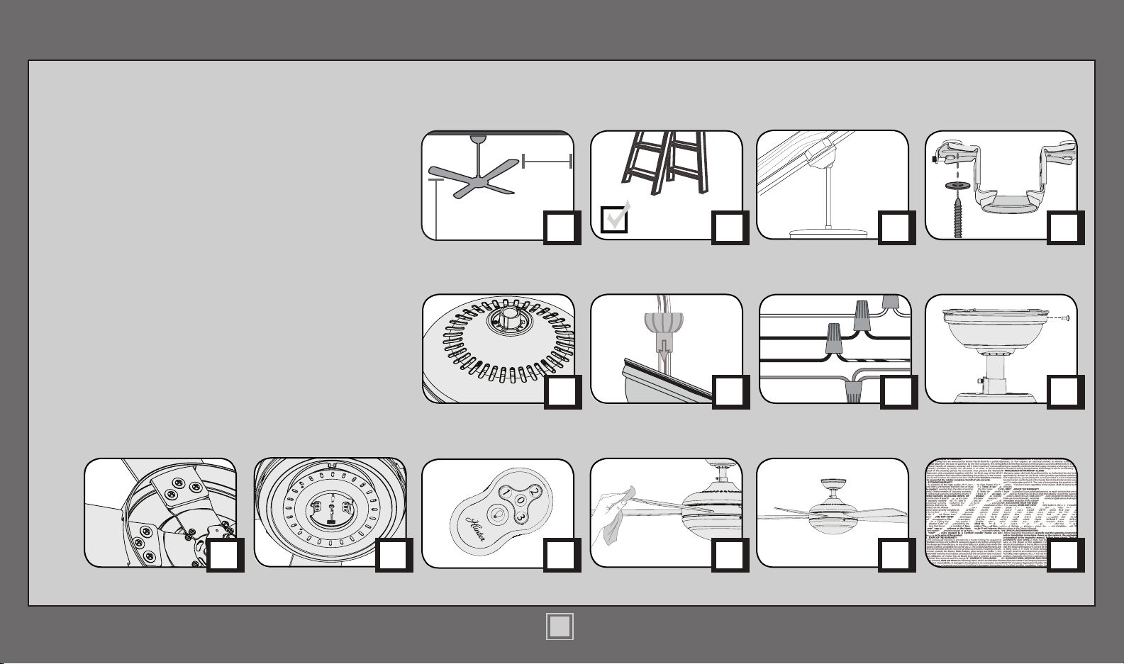
Table of Contents
Ladder
30 inches
7 feet
Congratulations on purchasing your new Hunter®
ceiling fan! It will provide comfort and performance
in your home or ofce for many years. This
installation and operation manual contains complete
instructions for installing and operating your fan.
We are proud of our work and appreciate the
opportunity to supply you with the best ceiling fan
available anywhere in the world.
What to Expect with
Your Installation
2
Assembling the Top
Housing
www.hunterfan.com.br
Tools Needed
PAG E
3
Downrod Canopy
Mounting Options
PAG E
4
Wiring
Ceiling Bracket
PAG E
PAG E
5
Blades
12
7
PAG E
Troubleshooting
10
PAG E
Warranty Statement
PAG E
11
Light Kit
Remote Control
PAG E
6
Operation,
Maintenance & Cleaning
?
?
PAG E
13
PAG E
PAG E
17
18
PAG E
?
PAG E
19
1
MD506-01 • 09/19/14 • © Hunter Fan Company
PAG E
20
Page 4
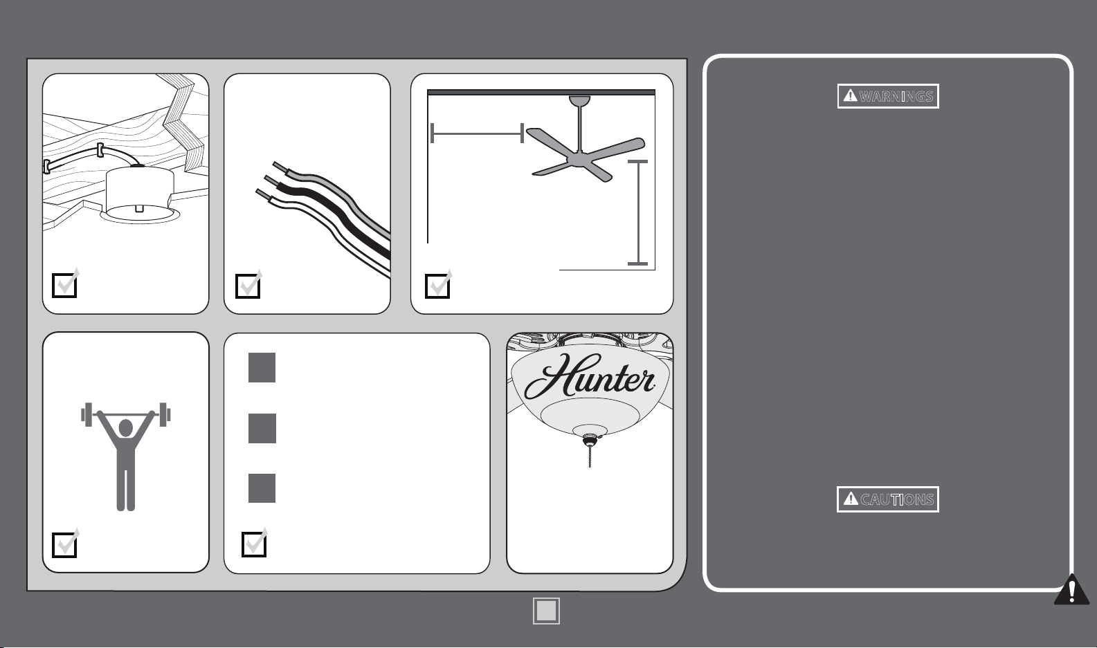
What to Expect with Your Installation
www.hunterfan.com.br
This product conforms to UL Standard 507.
Must be able to
secure the fan to
building structure or
fan-rated outlet box.
Do not use a plastic
outlet box.
You may need a
friend to help you.
Check box to see
fan weight
If you are unfamiliar
with wiring, use a
qualied electrician.
Know your wiring
Standard Downrod
1
for ceilings 2,4 -3 meters high
Shorter Downrod
2
for fans installed close to ceiling
Longer Downrod
3
for ceilings 3 meters or higher
Select a downrod length
0,50 meters
from blade tip to
nearest wall or
obstruction
Assess location
2,3 meters
from bottom
edge of blade to
the oor
Use ONLY Hunter
Ceiling Fan branded
accessory light kits.
WARNINGS
w.1 - To reduce the risk of re, electrical shock, or personal injury,
mount fan directly from building structure and/or an outlet
box marked acceptable for fan support of 31.8 kg and use the
mounting screws provided with the outlet box.
w.2 - To avoid possible electrical shock, before installing or
servicing your fan, disconnect the power by turning off the circuit
breakers to the outlet box and associated wall switch location. If
you cannot lock the circuit breakers in the off position, securely
fasten a prominent warning device, such as a tag, to the service
panel.
w.3 - To reduce the risk of re, electrical shock, or motor damage,
use only Hunter Solid State Speed Controls.
w.4 - To reduce the risk of personal injury, do not bend the blade
brackets when installing the blade brackets, balancing the blades, or
cleaning the fan. Do not insert foreign objects in between rotating fan
blades.
w.5 - This appliance is not intended for use by persons (including
children) with reduced physical, sensory or mental capabilities, or
people with a lack of experience and knowledge, unless they have
received instructions regarding the use of the device or under the
supervision of a person responsible for their safety.
w.6 - It is recommended that children be supervised to ensure that
they are not using the appliance improperly
CAUTIONS
c.1 - All wiring must be in accordance with national and local
electrical codes. If you are unfamiliar with wiring, use a qualied
electrician.
c.2 - Use only Hunter replacement parts.
2
MD506-01 • 09/19/14 • © Hunter Fan Company
Page 5
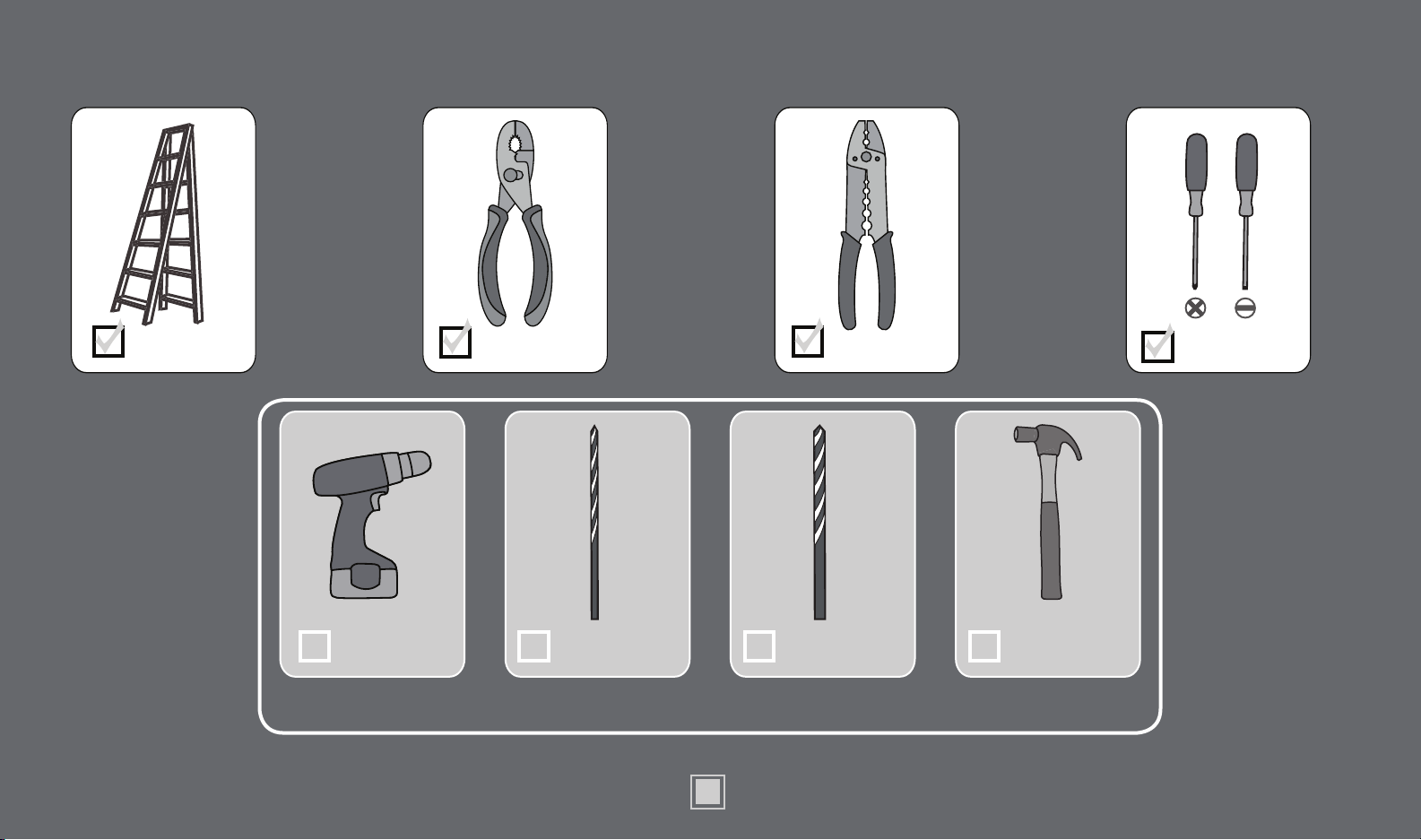
Tools Needed
www.hunterfan.com.br
Ladder
Power Drill
(optional)
Pliers Wire Strippers
3.5 mm Drill
Bit (optional)
If mounting to a support structure, you
will also need these tools.
8 mm Drill Bit
(optional)
3
MD506-01 • 09/19/14 • © Hunter Fan Company
Screwdrivers
Hammer
(optional)
Page 6
Mounting Options Ceiling Bracket
www.hunterfan.com.br
Support
Structure
Angled
Mounting
Style
Ceiling
Outlet Box
(required)
Structure
Standard
Mounting
Style
Support
Ceiling
Outlet Box
(required)
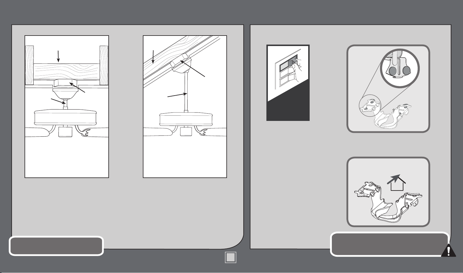
If you have a at ceiling: If you have an angled ceiling:
Hang your fan by a standard downrod
(included) or use a shorter downrod (sold
separately) for Low-Prole Mounting.
You will need a longer downrod (sold
separately) to hang the fan from a
vaulted or angled ceiling.
Note: Do not hang the fan from a
ceiling that is angled greater than 34°
Turn Power
OFF
Make sure all four (4) bumpers
are still attached.
For angled ceilings, point
opening toward peak.
Carefully choose the installation location
that allows for optimal air ow.
The support structure must be able to support 5
times the weight of the fan. The weight of the fan is
located on the product packaging.
4
MD506-01 • 09/19/14 • © Hunter Fan Company
Page 7
Ceiling Bracket (continued)
www.hunterfan.com.br
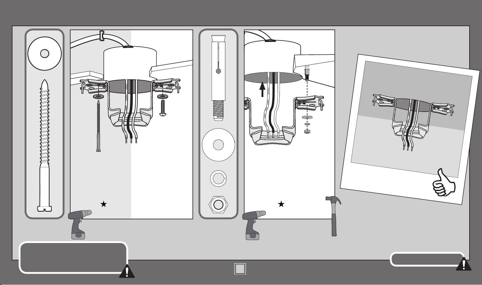
Use wood screws
(included) when securing
to support structure with
approved electrical outlet
box. Drill 3.5 mm pilot
holes in support structure
to aid in securing ceiling
bracket with hardware
found in the hardware
bag.
Note: Do not mount ceiling fan
to a plastic outlet box.
To avoid possible electrical shock, before
installing your fan, disconnect the power by
turning off the circuit breakers to the outlet
box associated with the wall switch location.
Use machine screws
(provided with outlet
box) when securing to
existing ceiling fan-rated
outlet box. Make sure
it is securely installed
and is acceptable for fan
support of 31.8 kg or less.
Use concrete anchors (included)
when securing to support structure
with approved outlet box in a concrete
ceiling. Drill 8 mm pilot holes in
support structure. Hammer the M6
expansion anchors into the holes until
the ends are ush with the ceiling.
Install the washer, isolator, and nut
found in the hardware bag to
the expansion anchors.
Refer to warning w.1 on pg. 2
5
MD506-01 • 09/19/14 • © Hunter Fan Company
Page 8

Assembling the Top Housing
KEEP!
E
E
P
K
!
www.hunterfan.com.br
Upper Motor
Cover Screw
Remove the pre-installed
setscrew so that the downrod
can be inserted.
To assemble the housing to the
hanger adapter, align the three
raised tabs on the hanger adapter
with the three narrow notches in
the top housing. Make certain the
housing sits at on the adapter.
MD506-01 • 09/19/14 • © Hunter Fan Company
Install three upper motor
cover screws, found in the
hardware bag, and tighten
them securely.
6
Page 9

Downrod
www.hunterfan.com.br
Standard
Downrod
for ceilings 2,4-3 m
high
Option 1Option 2
Shorter
Downrod
for fans installed
close to ceiling
Included
(pre-assembled)
Longer
Downrod
for angled
ceilings or
Option 3
ceilings 3 m or
higher
skip to next page
If you need a different downrod length follow these steps:
Steps 1-5 to remove standard downrod pipe
1 2 3 4 5
S lide
S lide
678910
Sold Separately
Sold Separately
Steps 6-10 to reassemble with new pipe
7
MD506-01 • 09/19/14 • © Hunter Fan Company
Page 10

Downrod (continued)
www.hunterfan.com.br
Hand tighten the downrod (at least 4-5 full
turns) until it stops.
1 cm
T
U
C
P
I
R
T
S
&
20 cm
(not to scale)
The wires can be cut, but leave at
least 20 cm extending from the top
Tighten the setscrew with pliers.
DO NOT HAND TIGHTEN.
of the downrod.
20 cm 1 cm
8
MD506-01 • 09/19/14 • © Hunter Fan Company
If the setscrew is not tightened
securely, the fan may fall.
Page 11

Downrod (continued)
www.hunterfan.com.br
Put the wires and downrod through the canopy.
Let the canopy sit loosely on top of the fan.
DO NOT PICK THE FAN UP BY THE CANOPY
OR WIRES. Place the downrod ball into the slot
in the ceiling bracket.
9
MD506-01 • 09/19/14 • © Hunter Fan Company
Page 12

Wiring
Note: To connect
www.hunterfan.com.br
the wires, hold the
E
C
I
L
I
M
N
O
R
F
G
bare metal leads
together and place a
wire connector over
C
E
E
I
R
V
M
O
R
F
E
R
E
I
C
L
I
N
M
O
R
F
G
them, then twist
clockwise until tight.
F
A
M
N
O
R
F
Using an orange wire
connector from
the hardware bag,
connect the 3 grounding
wires (green, green/
yellow stripe, or bare
copper) coming from the
ceiling, downrod, and
hanging bracket.
Refer to CAUTION c.1 on pg. 2
Green/Yellow
Stripe
F
R
O
M
C
Stripe
E
I
L
(Grounding)
Green/Yellow
I
G
N
blue
Using the orange wire
connectors from the remote
control hardware bag,
connect the blue wire from
the receiver to the black
with white stripe wire from
the fan. Connect the yellow
wire from the receiver to the
brown wire from the fan.
T
E
K
C
A
R
B
black with
white stripe
F
yellow
Using the orange wire
connectors from the
hardware bag, connect the
brown wire (ungrounded)
from the ceiling to the
black wire from the
receiver. Connect the blue
brown
R
N
O
A
F
M
wire from the ceiling to
both the white wire from
the receiver and the blue
wire from the fan.
Turn the splices upward and push them carefully back through the hanger bracket
into the outlet box. Spread the wires apart, with the grounded wires on one side of
the outlet box and the ungrounded wires on the other side of the outlet box.
brown
black
F
R
O
M
blue
F
A
M
N
O
R
F
blue
white
R
E
V
I
E
R
C
E
10
MD506-01 • 09/19/14 • © Hunter Fan Company
Page 13
Canopy
www.hunterfan.com.br
Screw
Holes
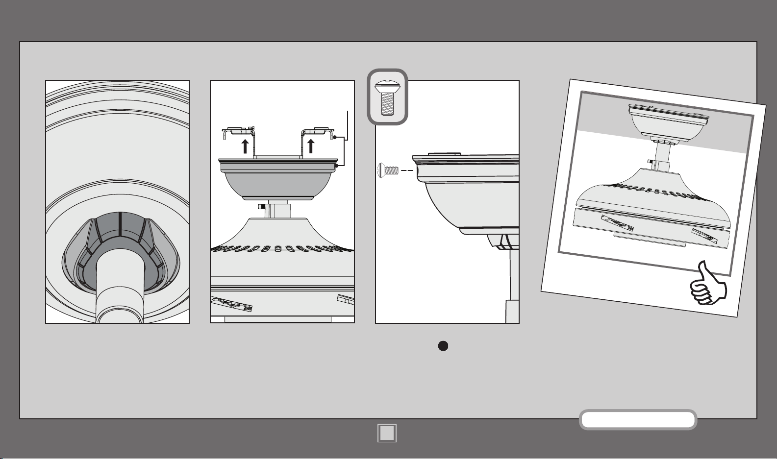
Position the canopy so that, when
lifted into place, the canopy ts into
the hanging bracket as shown.
Lift the canopy into place so that
the screw holes are aligned.
MD506-01 • 09/19/14 • © Hunter Fan Company
Insert the two canopy screws
found in the hardware bag.
Note: Fan style may vary.
11
Page 14

Blades
www.hunterfan.com.br
Holes
Insert blade into slot. Align the holes on the
blade with the holes in the fan motor.
Attach the blade to the motor using the at
washers from the hardware bag and blade
assembly screws found in the hardware bag.
Repeat for each blade.
12
MD506-01 • 09/19/14 • © Hunter Fan Company
Your blades are shielded with Dust Armor® which
is a nanotechnology coating that repels dust. For
cleaning the fan, use soft brushes or cloths to prevent
scratching. Cleaning agents may damage the nishes.
Page 15

Light Kit
www.hunterfan.com.br
Attachment Screw
Partially install two attachment
screws, found in the hardware
bag, into the light kit mounting plate.
Thread the 9-pin plug connector from the
fan through the light kit.
13
MD506-01 • 09/19/14 • © Hunter Fan Company
Align the keyholes in the light kit
with the two partially installed
screws and turn the light kit
clockwise until the screws are in the
narrow ends of the keyholes.
Page 16

Light Kit (continued)
www.hunterfan.com.br
Attachment Screw
Install the remaining attachment
screw to secure the light kit to the
mounting plate. Securely tighten all
three screws.
Make sure the light kit is securely attached to the mounting
plate. Failure to properly secure all three assembly screws
could result in the light xture falling.
Wire Slot
Thread the 2-pin connector through the
wire slot in the the switch housing.
14
MD506-01 • 09/19/14 • © Hunter Fan Company
Connect the upper 9-pin plug connector
from the fan to the lower 9-pin plug
connector in the light kit.
Page 17

Light Kit (continued)
www.hunterfan.com.br
Align the two screw screw holes and
install the switch housing assembly
screws, found in the hardware bag.
Wire Slot
Connect the the 2-pin plugs from the
switch housing and the LED assembly.
Push excess wiring into the switch
housing through the wire slot.
15
MD506-01 • 09/19/14 • © Hunter Fan Company
Light
Assembly
Screw
Attach the LED assembly to the
switch housing by installing two light
assembly screws, found in the
hardware bag, through the slots, not
the screw holes.
Page 18

Light Kit (continued)
www.hunterfan.com.br
Globe
Assembly
Screw
CONGRATULATIONS!
YOU’RE DONE!
Trim Ring
Glass Globe
Place the glass globe into the globe trim ring.
Align the three holes in the trim ring with
the three holes in the light kit. Install and
securely tighten all three globe assembly
screws, found in the hardware bag.
MD506-01 • 09/19/14 • © Hunter Fan Company
16
16
See next page for fan
operation instructions.
Page 19

Remote Control
Battery
Door
Phillips
Head
Screw
Fan Off
High
Fan
Off
Low
Speed
Medium
Speed
High
Speed
Light
www.hunterfan.com.br
Switch Cover
Plate
Removed
Tabs
Rocker- Style
Plate
To access the battery compartment,
remove the small Phillips head screw
that secures the battery door to the
transmitter assembly. The battery
should be installed with the positive
(+) side up. Replace with a CR2032
battery when necessary.
Turn Power
ON
Note: The remote must be paired
before the fan will operate.
Within 3 minutes of restoring power
to the fan, press both the Fan Off
button and the High button for at
least 4 seconds. Your fan will turn on
low to indicate successful syncing.
If it does not, turn off power to your
fan, wait 1 minute then try again. If
using the transmitter with multiple
fans, repeat this process for each fan.
MD506-01 • 09/19/14 • © Hunter Fan Company
To turn on fan, press a fan speed
button. Speeds range from off (0)
to high (3). Quickly press the Light
button to turn the lights off and on.
17
To install the transmitter cradle, remove
the two screws holding the switch
cover plate. Do not remove the cover
plate. Orient the cradle by lining up
the two mounting holes with those on
the cover plate. Insert and tighten the
screws. Do not over tighten.
Note: For rocker-style cover plates,
break off the tabs by pushing outward.
Page 20

Operation, Maintenance, & Cleaning
Safe-Exit
The Safe-Exit Program gives
you about thirty seconds of light
when you turn the lights off to
exit the room before the lights go
out. To use Safe-Exit:
• Press the Fan Off button for at
least three seconds to initiate the
Safe-Exit Mode.
• The lights will ash for visual
conrmation.
• The lights will stay on 50%
brightness for 15 seconds and
then begin to dim. After a total
of 30 seconds, the lights will be
completely off.
Note: For CFL lighting, the lights
will stay on 100% brightness for 30
seconds. After a total of 30 seconds,
the lights will be completely off.
Reverse
Switch
To switch the direction of air ow, remove
the globe on the fan by removing the globe
assembly screws, the glass, and trim ring. Flip
the black switch to change the direction.
www.hunterfan.com.br
For cleaning the fan, use soft brushes or
cloths to prevent scratching. Cleaning
products may damage the nishes.
18
MD506-01 • 09/19/14 • © Hunter Fan Company
Page 21

Troubleshooting
www.hunterfan.com.br
Fan doesn’t work
• Make sure power switch is on.
• Pull the pull chain to make sure
it is on.
• Push the motor reversing switch
rmly left or right to ensure that
it is engaged.
• Check the circuit breaker to
ensure the power is turned on.
• Make sure the blades spin freely.
• Turn off power from the circuit
breaker, then loosen the canopy
and check all the connections
according to the wiring diagram
on page 9.
• Check the plug connection in
the switch housing.
Excessive wobbling
• Tighten all of the blade and
blade iron screws until they
are snug.
• Turn the power off, support
the fan carefully, and check
that the hanger ball is
properly seated.
Remote control of fan is erratic
• Make sure the battery is
installed correctly.
• Install a fresh battery.
Transmitter only works when
held at close range
• Install a fresh battery.
Noisy Operation
• Tighten the blade and blade
iron screws until they are snug.
• Check to see if any of the
blades are cracked. If so, replace
all of the blades.
Lights dim when turned on or
do not turn on at all.
• Make sure the wattage of the
light bulbs installed matches
the specications on the light
sockets.
19
MD506-01 • 09/19/14 • © Hunter Fan Company
Page 22

I - TERM AND PROOF OF WARRANTY
1. Hunter Ceiling Fans are warranted by Hunter Fan do Brasil for a period of 1 (one) year from the date of purchase by the
rst consumer, this being:
• 3 (three) months of statutory warranty; and
• 9 (nine) months of contractual warranty provided by Hunter Fan do Brasil.
2. In order to demonstrate proof of the warranty period, the consumer must present this Warranty Statement, duly
completed, together with the 1st. (rst) copy of the bill of sale (or equivalent scal document identifying the product), in
the manner and at the location described in Section V below.
It is therefore necessary to ensure that the retailer completes the bill of sale correctly.
II - EXTENDED WARRANTY
1. As evidence of the high quality of Hunter Ceiling Fans, Hunter Fan do Brasil offers an Extended Warranty free of charge
for:
a. Three (3) years on the product, counted from the date of purchase by the rst consumer, this being:
• 3 (three) months of statutory warranty; and
• 33 (thirty three) months of contractual warranty provided by Hunter Fan do Brasil.
b. 10 (ten) years limited warranty on possible defects with the product motor, counted from the date of purchase by
the rst consumer, this being:
• 3 (three) months of statutory warranty; and
• 117 (one hundred and seventeen) months of contractual warranty provided by Hunter Fan do Brasil.
2. The Extended Warranty shall only be offered if the consumer registers the installation of the product on the Hunter
Fan do Brasil internet site (www.hunterfan.com.br) and correctly complete all required elds, including the date of
issue of the 1st (rst) copy of the bill of sale (or equivalent tax document) and details of the “Certied Hunter Installer
Certication Code” (*).
3. The Extended Warranty DOES NOT COVER the following parts:
a. Capacitors;
b. Fan blades and blade irons;
c. Glass xtures and parts thereof;
d. Controls and remote controls;
e. Ceiling fan mounting system.
*The “Certied Hunter Installer Certication Code” will be provided by the “Certied Hunter Installer” at the time that the product is installed.
4. You can locate a “Certied Installer Hunter” near your residence at the Hunter Fan do Brasil internet site (www.
hunterfan.com.br) or at Hunter Ceiling Fan retail outlets.
5. Installation costs charged by a Certied Installer Hunter are not included in the price of the product.
III - SCOPE OF THE WARRANTY
1. This contractual warranty is provided for a Hunter Ceiling Fan acquired in Brazilian territory and is offered exclusively
against any defects arising from the design and manufacture, or any other defects in quality, that render the product
unt or unsuitable for normal use.
2. The Contractual Warranty and the Extended Warranty do not cover product accessories, including controls, remote
controls, fan blades, blade holders, glass lamps and bulbs.
3. Any extended warranty that may be contracted by the consumer does not place any obligation on Hunter Fan do Brasil,
since such a contract is executed between the consumer and the insurer.
IV - WARRANTY EXCLUSIONS
1. The warranty does not cover the following items, which are therefore the consumer’s responsibility:
a) damage to the product or its accessories due to accident, abuse, or improper and incorrect handling;
b) damage to the product as a result of its use for purposes other than those specied by Hunter Fan do Brasil, or that are
incompatible with the purpose of the product;
c) improper installation, or installation on a structure that is not suitable to support the product, or that exposes an
electrical product to adverse conditions;
d) defects in the electrical parts of the product caused by deciencies in external wiring or caused by the local electrical
supply company.
e) damages resulting from accidents during transportation and storage or due to mishandling.
WARRANTY STATEMENT
www.hunterfan.com.br
V - PROCEDURE FOR WARRANTY CLAIMS
1. Warranty repairs shall only be performed by an Authorized Service Center appointed by Hunter Fan do Brasil, which
provides specialized technicians and original parts, guaranteeing the service provided.
2. A list of Authorized Service Centers can be found at the Hunter Fan do Brasil internet site:
www.hunterfan.com.br.
3. The cost of transporting the product to the Authorized Service Center, regardless of the reason, shall be borne by the
consumer.
VI - RESCISSION OF THE WARRANTY
1. Repair of a product by unauthorized persons or repair services that are not accredited by Hunter Fan do Brasil shall
immediately rescind the warranty.
2. Hunter Ceiling Fans are solely and exclusively designed for domestic use. Their use in non-domestic, industrial or
commercial applications shall signify immediate rescission of the warranty.
VII - EXCLUSIONS FROM THE WARRANTY
1. This warranty DOES NOT COVER:
a. light bulbs;
b. the cost of installing the product;
c. calls related to information that is contained in the Owner’s Manual, or is shown on the product itself. These service
calls shall be charged if they occur;
d. damage to plastic parts;
e. implicit warranties - This warranty replaces all other warranties, implicit or implied, and no representative or third party
is authorized to assume any other obligation relating to the sale of Hunter ventilators on behalf of Hunter Fan do Brasil.
2. Hunter Fan do Brasil shall not be liable for any direct, indirect or consequential damages resulting from the use or
performance of the product, nor other losses relating to material damage or pecuniary losses due to non-compliance
with the instructions in the Owner’s Manual.
VIII - SPECIAL RECOMMENDATIONS
1. Before operating the product, carefully read the operating instructions and/or installation instructions shown on
the product, the packaging, or contained in the respective manual. Follow them closely. They are provided for
your safety.
2. Make sure that the voltage to be used is the same as that shown on the appliance (127 V or 220 V). Ensure that the
electrical installation at the location is correct and in perfect order, and also that the electrical frequency is correct for the
country in which the product is being used.
3. In order to avoid damage, keep the product clean and properly stored in an environment protected from the weather
(rain, wind, humidity, solar radiation, etc.).
4. Do not insert any foreign objects into the product, especially when it is in operation, in order to avoid accidents.
IX - MANUFACTURER, IMPORTER AND PRODUCT INFORMATION
Manufacturer: Hunter Fan Company
Importer: Hunter Fan do Brasil Ltda.
011.2985.7454
CNPJ: 20.089.903/0001-06
contatobrasil@hunterfan.com
Product Model:
Lot:
Certied Installer Installation Code:
Consumer:
Personal Tax Number (“CPF”):
Place of purchase:
Date of Purchase:
Bill of Sale or Tax Invoice Number:
20
MD506-01 • 09/19/14 • © Hunter Fan Company
 Loading...