

Page 1

11
1
11
© 2003 Hunter Fan Company 41814-01 01/14/2003
Page 2
22
2
22
®
Your new Hunter® ceiling fan is an addition to your home or office
that will provide comfort and performance for many years. This
installation and operation manual gives you complete instructions
for installing and operating your fan.
We are proud of our work. We appreciate the opportunity to supply you with the best ceiling fan available anywhere in the world.
Before installing your fan, record the following information for your
records and warranty assistance. Please refer to the carton and the
Hunter nameplate label (located on the top of the fan motor housing) for the proper information.
Model Name: __________________________
Catalog/Model No.: ______________
Serial No.: _____________________
Date Purchased: ___ / ___ / ______
Where Purchased: _______________________________
Please also attach your receipt or a copy of your receipt for reference.
cautions and warnings
••
RR
ee
aa
d ed e
nn
tt
irir
e be b
oo
oo
kk
ll
ee
t ct c
aa
rr
ee
ff
ullull
y by b
ee
ff
oo
rr
e be b
ee
gg
inninn
inin
g ing in
ss
tt
•
R
e
a
d e
n
t
ir
e b
o
o
k
l
e
t c
a
r
e
f
ull
y b
e
f
o
r
e b
e
g
••
RR
ee
aa
d ed e
nn
tt
irir
e be b
oo
oo
kk
ll
ee
t ct c
aa
rr
ee
ff
ullull
y by b
ee
ff
oo
ll
aa
tt
ii
oo
nn
. S. S
aa
vv
e te t
hh
ee
ss
e ine in
ss
tt
rr
uu
cc
tt
ii
oo
nn
ss
l
a
t
i
o
n
. S
a
v
e t
h
e
s
e in
s
t
r
ll
aa
tt
ii
oo
nn
. S. S
aa
vv
e te t
hh
ee
••
UsUs
e oe o
nlnl
y Hy H
unun
tt
ee
•
Us
e o
nl
e oe o
o ro r
o r
o ro r
ee
e
ee
oo
rr
o
r
oo
rr
aa
rr
a
r
aa
rr
o ao a
o a
o ao a
oo
ur fur f
o
ur f
oo
ur fur f
uiui
ui
uiui
ww
ii
w
i
ww
ii
rr
s in ts in t
r
s in t
rr
s in ts in t
aa
rr
a
r
aa
rr
ll wll w
ll w
ll wll w
oo
cc
o
c
oo
cc
ff
f
ff
rr
ii
cc
r
i
c
rr
ii
cc
o ro r
o r
o ro r
ll
aa
l
a
ll
aa
r cr c
r c
r cr c
ww
ee
w
e
ww
ee
o ro r
o r
o ro r
aa
mm
a
m
aa
mm
hh
ii
s fs f
h
i
s f
hh
ii
s fs f
ee
e
ee
cc
c
cc
dindin
din
dindin
e se s
e s
e se s
t bt b
t b
t bt b
tt
cc
t
c
tt
cc
nn
n
nn
aa
l el e
a
l e
aa
l el e
aa
a
aa
ii
aa
i
a
ii
aa
ee
e
ee
dd
d
dd
ll
l
ll
ee
e
ee
ee
e
ee
dudu
du
dudu
tt
t
tt
vv
v
vv
h lh l
h l
h lh l
inin
in
inin
irir
ir
irir
mm
m
mm
nn
n
nn
dudu
du
dudu
e ae a
e a
e ae a
ee
e
ee
n rn r
n r
n rn r
dudu
du
dudu
aa
a
aa
aa
a
aa
nlnl
oo
o
oo
aa
a
aa
gg
g
gg
ll
l
ll
aa
a
aa
r
nn
n
nn
y H
y Hy H
y ty t
y t
y ty t
g tg t
g t
g tg t
upup
up
upup
ii
d pd p
i
d p
ii
d pd p
nn
n
nn
rr
ee
e
rr
ee
o
hh
h
hh
g dg d
g d
g dg d
inin
in
inin
ll
ee
l
e
ll
ee
iliili
ili
iliili
..
.
..
cc
c
cc
tt
t
tt
nn
n
nn
oo
o
oo
ee
e
ee
. Us. Us
. Us
. Us. Us
cc
c
cc
aa
a
aa
oo
oo
cc
c
cc
, d, d
, d
, d, d
••
UsUs
••
TT
•
T
••
TT
dirdir
dir
dirdir
cc
c
cc
ww
w
ww
••
TT
•
T
••
TT
yy
y
yy
cc
c
cc
ss
s
ss
ee
e
ee
ww
w
ww
••
AA
•
A
••
AA
ll
l
ll
unun
un
unun
tt
t
tt
••
TT
•
T
••
TT
bb
b
bb
oo
o
oo
tt
t
tt
••
TT
•
T
••
TT
dd
d
dd
tt
t
tt
un
unun
e te t
e t
e te t
o to t
o t
o to t
o to t
o t
o to t
pp
lili
p
li
pp
lili
, di, di
, di
, di, di
kk
ee
k
e
kk
ee
cc
aa
c
a
cc
aa
e oe o
e o
e oe o
ee
e
ee
g mug mu
g mu
g mug mu
cc
tt
rr
c
t
r
cc
tt
rr
aa
r wr w
a
r w
aa
r wr w
e te t
e t
e te t
tt
aa
cc
t
a
c
tt
aa
cc
inin
g tg t
in
g t
inin
g tg t
tt
aa
tt
t
a
t
tt
aa
tt
e te t
e t
e te t
o no n
o n
o no n
hh
h
hh
hh
h
hh
hh
h
hh
ee
d.d.
e
d.
ee
d.d.
oo
ss
o
s
oo
ss
ss
cc
s
c
ss
cc
rr
s ts t
r
s t
rr
s ts t
tt
ii
oo
t
i
o
tt
ii
oo
ff
f
ff
vv
ii
v
i
vv
ii
ii
cc
i
c
ii
cc
ii
i
ii
hh
e re r
h
e r
hh
e re r
hmhm
hm
hmhm
h
inin
in
inin
hh
h
hh
e oe o
e o
e oe o
t
tt
e re r
e r
e re r
e se s
e s
e se s
ee
e
ee
sibsib
sib
sibsib
oo
o
oo
f pf p
f p
f pf p
cc
c
cc
aa
a
aa
tt
h wh w
t
h w
tt
h wh w
hh
hh
g fg f
g f
g fg f
e re r
e r
e re r
oo
o
oo
e
ee
ss
s
ss
nnnn
nn
nnnn
nn
n
nn
ee
e
ee
ss
s
ss
l cl c
l c
l cl c
ee
e
ee
e fe f
e f
e fe f
nl
r rr r
r r
r rr r
e ine in
e in
e ine in
o to t
o t
o to t
. I. I
. I
. I. I
, s, s
, s
, s, s
t bt b
t b
t bt b
ii
i
ii
t ut u
t u
t ut u
nlnl
nlnl
ss
ii
i
ii
ll
l
ll
oo
o
oo
ss
s
ss
nn
n
nn
aa
a
aa
ii
i
s
ii
ss
s
ss
upup
up
upup
o
k ok o
k o
k ok o
ss
ss
e ine in
k ok o
k o
k ok o
e ee e
e e
e ee e
ee
e
ee
sisi
si
sisi
uu
u
uu
oo
oo
irir
ir
irir
t st s
t s
t st s
aa
a
aa
n bn b
n b
n bn b
k ok o
k o
k ok o
y Hy H
y H
y Hy H
ss
ee
pp
ll
aa
e
p
l
a
ee
pp
ll
aa
f pf p
f p
f pf p
pp
oo
p
o
pp
oo
ss
tt
rr
s
t
r
ss
tt
rr
ll
ee
l
e
ll
ee
cc
t tt t
c
t t
cc
t tt t
hh
e oe o
h
e o
hh
e oe o
f yf y
oo
f y
o
f yf y
oo
tt
ii
oo
t
i
o
tt
ii
oo
cc
h ah a
c
h a
cc
h ah a
e in ae in a
e in a
e in ae in a
dd
ee
s as a
d
e
s a
dd
ee
s as a
inin
gg
in
g
inin
gg
f pf p
f p
f pf p
yy
ss
y
s
yy
ss
nn
. N. N
n
. N
nn
. N. N
ll
aa
l
a
ll
aa
f ff f
f f
f ff f
ss
e a se a s
s
e a s
ss
e a se a s
unun
un
unun
tt
rr
cc
c
cc
rr
r
t s
rr
uu
u
uu
cc
c
cc
hh
h
hh
u cu c
u c
u cu c
nn
n
nn
s a ts a t
s a t
s a ts a t
, y, y
, y
, y, y
ee
e
ee
tt
ee
t
e
tt
ee
dd
d
dd
u
uu
ee
e
ee
t st s
t st s
cc
c
cc
tt
t
tt
e pe p
e p
e pe p
uu
u
uu
, s, s
, s
, s, s
n
ee
e
ee
irir
ir
irir
tt
t
tt
c
t
cc
tt
mm
m
mm
ee
rr
ss
e
r
s
ee
rr
ss
tt
t
tt
tt
ii
oo
t
i
o
tt
ii
oo
rr
ii
cc
r
i
c
rr
ii
cc
tt
ll
ee
t
l
e
tt
ll
ee
aa
nnnn
a
nn
aa
nnnn
ee
e
ee
cc
cc
c
c
cc
cc
nn
d Ad A
d A
nn
d Ad A
oo
u su s
o
u s
oo
u su s
rr
ss
oo
r
s
o
rr
ss
oo
m wm w
m w
m wm w
vv
ee
v
e
vv
ee
ee
ss
e
s
.
ee
ss
ee
, e, e
e
, e
ee
, e, e
oo
lili
o
li
oo
lili
ee
r sr s
e
r s
ee
r sr s
i
o
ii
oo
ee
e
ee
oo
o
oo
rr
uu
r
u
rr
uu
nn
n
nn
aa
a
aa
oo
o
oo
t bt b
t b
t bt b
cc
c
cc
aa
a
aa
oo
o
oo
nn
n
nn
r inr in
r in
r inr in
..
..
d-d-
d-
d-d-
pp
p
pp
nn
n
nn
ww
w
ww
urur
ur
urur
rr
r
rr
nn
n
nn
l sl s
l s
l sl s
gg
g
gg
dd
d
dd
NN
N
NN
hh
h
hh
aa
a
aa
hh
h
hh
ll
l
ll
ss
s
ss
n
nn
t pt p
t p
t pt p
cc
c
cc
ss
s
ss
oo
o
oo
ee
e
ee
ee
e
ee
s
ss
aa
l inl in
a
l in
aa
l inl in
tt
urur
t
ur
tt
urur
, a, a
, a
, a, a
hh
h
hh
ee
e
ee
oo
o
oo
t lt l
t l
t lt l
ee
e
ee
, t, t
, t
, t, t
aa
a
aa
SS
S
SS
oo
o
oo
l inl in
l in
l inl in
ee
e
ee
ss
s
ss
cc
c
cc
tt
aa
t
a
tt
aa
ee
e
ee
..
.
..
aa
a
aa
nn
n
nn
oo
o
oo
r br b
r b
r br b
x ax a
x a
x ax a
oo
o
oo
ll
y fy f
l
y f
ll
y fy f
o to t
o t
o to t
nn
cc
n
c
nn
cc
I/NI/N
I/N
I/NI/N
ulul
d ud u
ul
d u
ulul
d ud u
jurjur
jur
jurjur
n inn in
n in
n inn in
ee
rr
e
r
ee
rr
tt
rr
ii
t
r
i
tt
rr
ii
tt
e se s
t
e s
tt
e se s
d cd c
d c
d cd c
rr
r
rr
e oe o
e o
e oe o
t ft f
t f
t ft f
rr
tt
t
tt
jurjur
jur
jurjur
d ud u
d u
d ud u
cc
kk
c
k
cc
kk
y ty t
y t
y ty t
n
cc
k tk t
c
k t
cc
k tk t
aa
a
aa
hh
h
hh
e we w
e w
e we w
cc
aa
c
a
cc
aa
oo
o
oo
ss
s
ss
nn
nn
FF
F
FF
ss
s
ss
e be b
ee
..
.
..
yy
, a, a
y
, a
yy
, a, a
f tf t
hh
f t
h
f tf t
hh
ss
e oe o
s
e o
ss
e oe o
, b, b
ee
, b
e
, b, b
ee
urur
nn
ur
n
urur
nn
d ad a
d a
d ad a
hh
e ce c
h
e c
hh
e ce c
ss
tt
ee
n a pn a p
s
t
e
n a p
ss
tt
ee
n a pn a p
e se s
ee
e s
e
e se s
ee
ii
tt
i
t
h n
ii
tt
PP
A 70. IA 70. I
P
A 70. I
PP
A 70. IA 70. I
ss
e a qe a q
s
e a q
ss
e a qe a q
yy
, d, d
y
, d
yy
, d, d
tt
aa
llinllin
t
a
llin
tt
aa
llinllin
oo
rr
ee
ii
o
r
e
i
oo
rr
ee
ii
l sl s
hh
l s
h
l sl s
hh
pp
ee
ee
p
e
e
pp
ee
ee
nn
tt
rr
oo
n
t
r
o
nn
tt
rr
oo
gg
e be b
e b
e be b
ff
f
ff
inin
in
inin
ss
s
ss
rr
r
rr
h nh n
h nh n
o no n
o n
o no n
gg
g
gg
oo
o
oo
d cd c
d c
d cd c
ll
l
ll
inn
inninn
tt
tt
t
t
tt
tt
nlnl
nl
nlnl
oo
rr
o
r
oo
rr
g og o
g o
g og o
ss
oo
s
o
ss
oo
irir
ir
irir
vv
ii
v
i
vv
ii
uu
u
uu
gg
g
gg
n on o
n o
n on o
cc
c
cc
ss
..
s
.
ss
..
aa
cc
a
c
aa
cc
uiluil
uil
uiluil
y ty t
y t
y ty t
e ine in
e in
e ine in
cc
c
cc
cc
c
cc
cc
e pe p
c
e p
cc
e pe p
aa
tt
a
t
aa
tt
aa
a
aa
oo
t bt b
o
t b
oo
t bt b
, b, b
, b
, b, b
kk
, o, o
k
, o
kk
, o, o
oo
nn
o
n
oo
nn
in
inin
h th t
h t
h th t
ii
aa
i
a
ii
aa
uiui
ui
uiui
rr
r
rr
ii
i
ii
lili
li
lili
bb
b
bb
hh
h
hh
ff
f tf t
f
f t
ff
f tf t
t
oo
o
oo
oo
o
oo
f yf y
f y
f yf y
ff
f
ff
aa
a
aa
jj
j
jj
tt
t
tt
g in
g ing in
dindin
din
dindin
e he h
e h
e he h
ss
s
ss
tt
ee
e
tt
ee
t bt b
t b
t bt b
mm
m
mm
aa
a
aa
nn
n
nn
ii
ee
i
e
ii
ee
ee
e
ee
ll
aa
l
a
ll
aa
ee
cc
e
c
ee
cc
r mr m
r m
r mr m
rr
oo
r
o
rr
oo
hh
e fe f
h
e f
hh
e fe f
g ag a
g a
g ag a
tt
aa
t
a
tt
aa
hh
e ce c
h
e c
hh
e ce c
d wd w
d w
d wd w
rr
r
rr
inin
in
inin
nn
ee
n
e
nn
ee
aa
l al a
a
l a
aa
l al a
oo
u au a
o
u a
oo
u au a
d ed e
d e
d ed e
nn
d td t
n
d t
nn
d td t
nn
cc
n
c
nn
cc
tt
s bs b
t
s b
tt
s bs b
l wl w
l w
l wl w
s
t
ss
tt
aa
a
aa
llinllin
llin
llinllin
ee
e
ee
ee
e
ee
l.l.
l.
l.l.
ll
l
ll
inin
in
inin
oo
o
oo
aa
a
aa
aa
a
aa
rr
d-d-
r
d-
rr
d-d-
irir
ir
irir
aa
a
aa
aa
a
aa
nn
n
nn
nn
n
nn
rr
r
rr
ee
e
ee
hh
h
hh
tt
oo
t
o
tt
oo
ii
tt
i
t
ii
tt
getting ready
To install a ceiling fan, be sure you can do the following:
• Locate the ceiling joist or other suitable support in ceiling.
• Drill holes for and install wood screws.
• Identify and connect electrical wires.
• Lift 40 pounds.
kk
k
kk
e-e-
e-
e-e-
If you need help installing the fan, your Hunter fan dealer can direct you to a licensed installer or electrician.
gathering the tools
You will need the following tools for installing the fan:
• Electric drill with 9/64" bit
• Standard screwdriver
• Phillips-head screwdriver
• Wrench or pliers
considering optional accessories
Consider using Hunter’s optional accessories, including a wallmounted or remote speed control. To install and use the accessories, follow the instructions included with each product. For quiet
and optimum performance of your Hunter fan, use only Hunter
speed controls.
checking your fan parts
Carefully unpack your fan to avoid damage to the fan parts. Check
for any shipping damage to the motor or fan blades. If one of the
fan blades was damaged in shipment, return all the blades for replacement.
NOTE: If you are installing more than one fan, keep the fan blades
l-l-
l-
l-l-
nn
n
nn
cc
--
c
-
cc
--
gg
g
gg
--
-
--
llll
ll
llll
--
-
-tt
t
tt
dd
d
dd
ee
e
ee
cc
--
c
-
cc
--
ee
e
ee
gg
,,
g
,
gg
,,
rr
r
rr
hh
h
hh
in sets, as they were shipped.
If any parts are missing or damaged, contact your Hunter dealer or
call Hunter Parts Department at 888-830-1326.
understanding Installer’s Choice
dd
d
dd
ss
h mh m
s
h m
ss
h mh m
aa
a
aa
rr
d md m
r
d m
rr
d md m
®
10”
oo
unun
tt
inin
gg
o
un
t
in
g
oo
unun
tt
inin
gg
12”
oo
unun
tt
inin
gg
o
un
t
in
g
oo
unun
tt
inin
gg
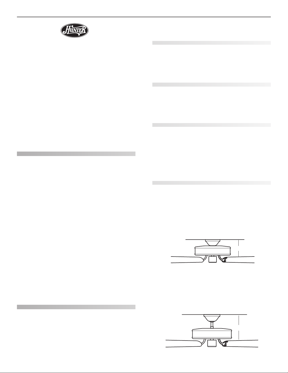
This patented 3-position mounting system provides you maximum
installation flexibility and ease. You can install your Hunter fan in
one of three ways. The steps in this manual include specific instructions for the fan mounting method of your choice. For a ceiling 8
feet or higher, standard mounting is recommended.
FF
lulu
ss
h Mh M
oo
unun
tt
inin
F
lu
s
h M
FF
lulu
ss
h Mh M
gg
o
un
t
in
g (Figure 1) fits close to the ceiling, for low ceilings
oo
unun
tt
inin
gg
less than 8 feet high.
FF
ii
gg
urur
e 1 - Fe 1 - F
e 1 - F
e 1 - Fe 1 - F
lulu
lu
lulu
F
i
g
ur
FF
ii
gg
urur
SS
tt
aa
nn
dd
aa
rr
d Md M
oo
unun
tt
inin
S
t
a
n
d
a
r
SS
d M
tt
aa
nn
dd
aa
rr
d Md M
gg
o
un
t
in
g (Figure 2) hangs from the ceiling by a downrod
oo
unun
tt
inin
gg
(included), for ceilings 8 feet or higher. For ceilings higher than 8
feet, you can purchase Hunter extension downrods. All Hunter
fans use sturdy 3/4" diameter pipe to assure stability and wobblefree performance.
FF
ii
gg
urur
e 2 - Se 2 - S
tt
aa
e 2 - S
e 2 - Se 2 - S
nn
t
a
n
tt
aa
nn
F
i
g
ur
FF
ii
gg
urur
41814-01 01/14/2003 © 2003 Hunter Fan Company
Page 3
33
3
33
AA
nn
gg
ll
e Me M
oo
unun
tt
inin
A
n
g
l
e M
AA
nn
gg
ll
e Me M
gg
o
un
t
in
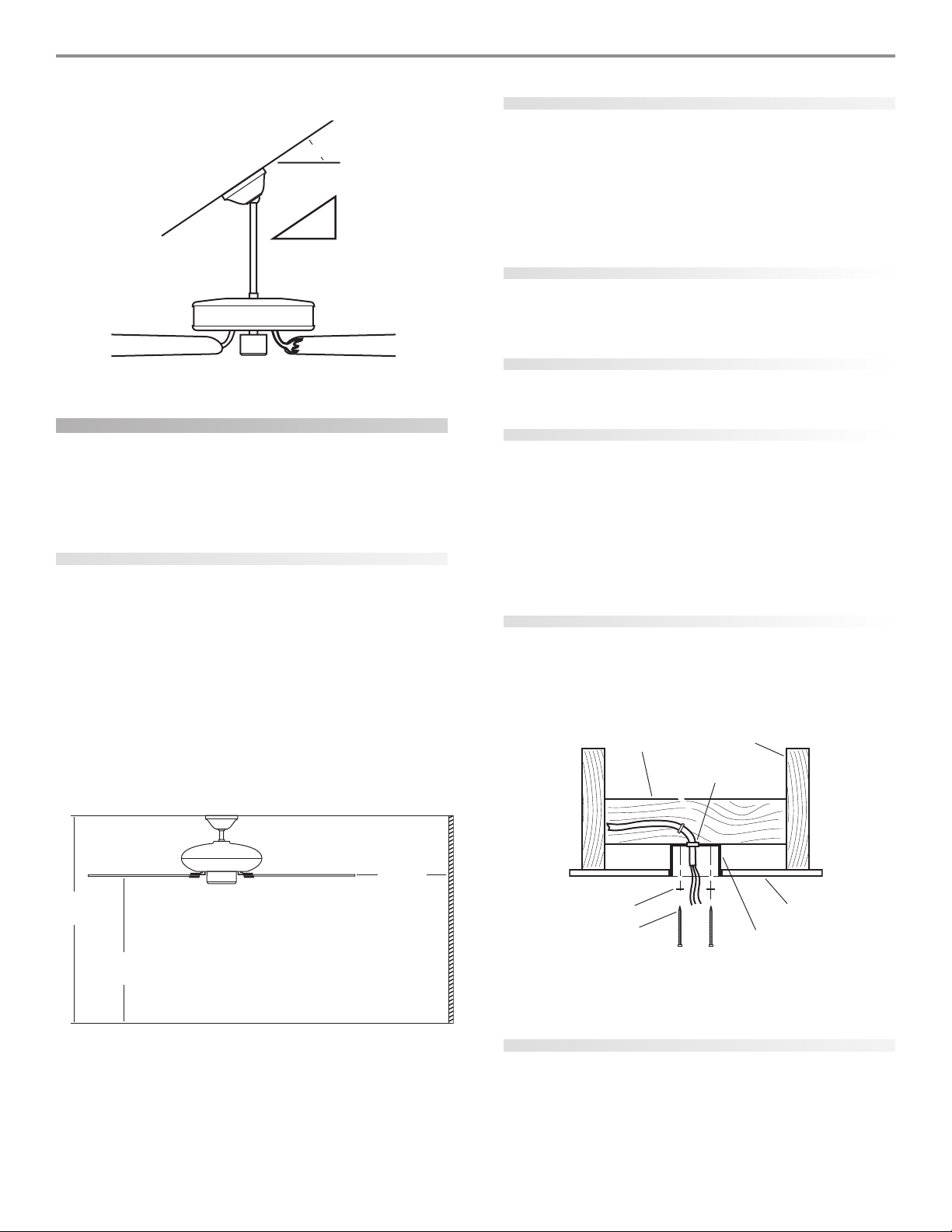
g (Figure 3) hangs from a vaulted or angled ceiling.
oo
unun
tt
inin
gg
34º Max
using an existing fan site
If you are preparing a new fan site, go to the
sisi
tt
ee
si
t
e section.
sisi
tt
ee
pp
rr
ee
pp
aa
rr
inin
g a ng a n
ee
w fw f
aa
p
r
e
p
a
r
in
pp
g a n
rr
ee
pp
aa
rr
inin
g a ng a n
e
ee
w f
w fw f
nn
a
n
aa
nn
If you plan to use an existing fan site, complete the following checklist for the support brace, ceiling hole, outlet box, and wiring. If you
pp
rr
ee
pp
aa
rr
inin
g a ng a n
ee
w fw f
aa
n sin si
tt
a
aa
n si
n sin si
ee
t
e sec-
tt
ee
Pitch
12
8
cannot check off every item, see the
tion for instructions on properly preparing the site for your new
p
r
e
p
a
r
in
g a n
e
pp
rr
ee
pp
aa
rr
inin
g a ng a n
w f
ee
w fw f
fan.
fan support system
• Fan must attach directly to building structure.
• Fan support system must hold full weight of fan and light
kit.
FF
ii
gg
urur
e 3 - Ae 3 - A
nn
gg
ll
e me m
oo
unun
tt
inin
F
i
g
ur
e 3 - A
n
g
l
FF
ii
gg
urur
e 3 - Ae 3 - A
e m
nn
gg
ll
e me m
gg
o
un
t
in
g
oo
unun
tt
inin
gg
preparing the fan site
These guidelines are designed to help you select the best location
for your fan and to prepare the site prior to installing the fan. Proper
ceiling fan location and attachment to the building structure are
essential for safety, reliable operation, maximum efficiency, and energy savings.
choosing the fan site
Within the room where you want to install the fan, choose a fan
site where:
• No object can come in contact with the rotating fan blades
during normal operation.
• The fan blades are at least 7 feet above the floor and the
ceiling is at least 8 feet high.
• The fan blades have no obstructions to air flow, such as
walls or posts, within 30 inches of the fan blade tips.
• The fan is directly below a joist or support brace that will
hold the outlet box and the full weight of the fan.
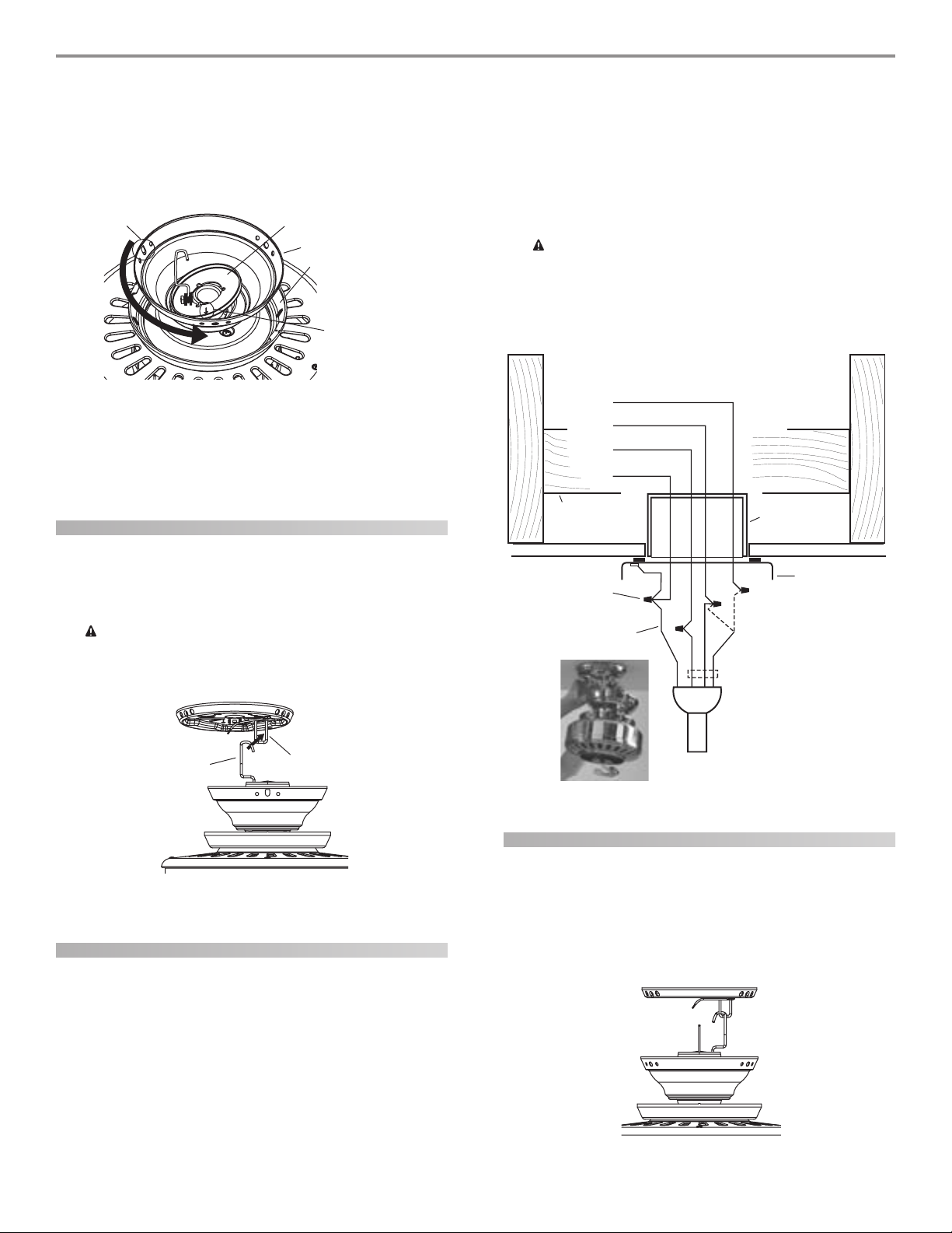
See Figure 4 for the minimum mounting distances.
ceiling hole
• Outlet box clearance hole directly below the joist or support brace.
outlet box
• UL-approved octagonal 4" x 1-1/2" outlet box (or as specified by the support brace manufacturer).
• Outlet box secured to joist or support brace by wood
screws and washers through inner holes of outlet box.
• Outer holes of outlet box aligned with joist or support
brace.
• Bottom of outlet box recessed a minimum of 1/16" into
ceiling.
wiring
• Electrical cable secured to outlet box by approved connector.
• Six inches of lead wires extend from outlet box.
See Figure 5 for an adequate existing fan site.
Support Brace
Ceiling Joist
Approved
Connector
30” From
aa
a
aa
nn
cc
n
c
nn
cc
ee
ss
e
s
ee
ss
Wall or
Nearest
Obstruction
Washer
Wood Screw
FF
ii
gg
urur
e 5 - Ae 5 - A
dd
ee
qq
F
i
g
ur
e 5 - A
FF
ii
gg
urur
e 5 - Ae 5 - A
uu
d
e
q
u
dd
ee
qq
uu
If your existing fan site is suitable, go to the
pp
ll
aa
tt
ee
p
l
a
t
e section and begin installing your new Hunter fan.
pp
ll
aa
tt
ee
Outlet Box
aa
tt
e exe ex
ii
ss
tt
inin
g fg f
a
t
e ex
aa
tt
e exe ex
aa
i
s
t
in
g f
a
ii
ss
tt
inin
g fg f
aa
inin
in
inin
preparing a new fan site
Ceiling
n sin si
n si
n sin si
ss
tt
s
t
ss
tt
tt
ee
t
e
tt
ee
aa
llinllin
g tg t
hh
e ce c
ee
a
llin
g t
aa
llinllin
g tg t
ilinilin
h
e c
e
ilin
hh
e ce c
ee
ilinilin
8’ Minimum
Ceiling Height
7’ Minimum
to Floor
FF
ii
gg
urur
e 4 - Me 4 - M
inin
F
i
g
ur
e 4 - M
FF
ii
gg
urur
e 4 - Me 4 - M
imum mimum m
in
imum m
inin
imum mimum m
oo
unun
tt
inin
g dig di
ss
o
un
oo
unun
tt
t
in
g di
s
t
tt
inin
g dig di
ss
tt
To prepare the fan site follow four steps:
• Cutting the Ceiling Hole
• Installing the Support Brace (if necessary)
• Installing the Outlet Box
• Preparing the Wiring
© 2003 Hunter Fan Company 41814-01 01/14/2003
gg
g
gg
Page 4
44
4
44
cutting the ceiling hole
1. Locate the site for the hole directly below the joist or support
brace that will hold the outlet box and fan.
2. Cut a 4" diameter hole through the drywall or plaster of the
ceiling as shown in Figure 6. You will use the hole to install the
support brace and outlet box.
tt
tt
inin
t
t
in
tt
tt
inin
Ceiling Joist
4”
Diameter
Ceiling
Hole
g tg t
hh
e ce c
g t
h
e c
g tg t
hh
e ce c
Ceiling
ee
ilinilin
g hg h
oo
ll
ilin
ilinilin
g h
g hg h
ee
o
l
e
oo
ll
ee
e
ee
Support Brace
FF
ii
gg
urur
e 6 - Ce 6 - C
e 6 - C
e 6 - Ce 6 - C
uu
u
uu
F
i
g
ur
FF
ii
gg
urur
installing the support brace
If there is a ceiling joist directly above the hole which will allow the
outlet box to be recessed a minimum of 1/16" in the ceiling, go to
inin
ss
tt
aa
llinllin
g tg t
hh
e oe o
uu
tt
ll
ee
t bt b
oo
in
inin
s
t
a
llin
g t
h
e o
g tg t
u
hh
e oe o
uu
ss
tt
aa
llinllin
t
tt
l
e
ll
ee
t b
t bt b
xx
o
x section.
oo
xx
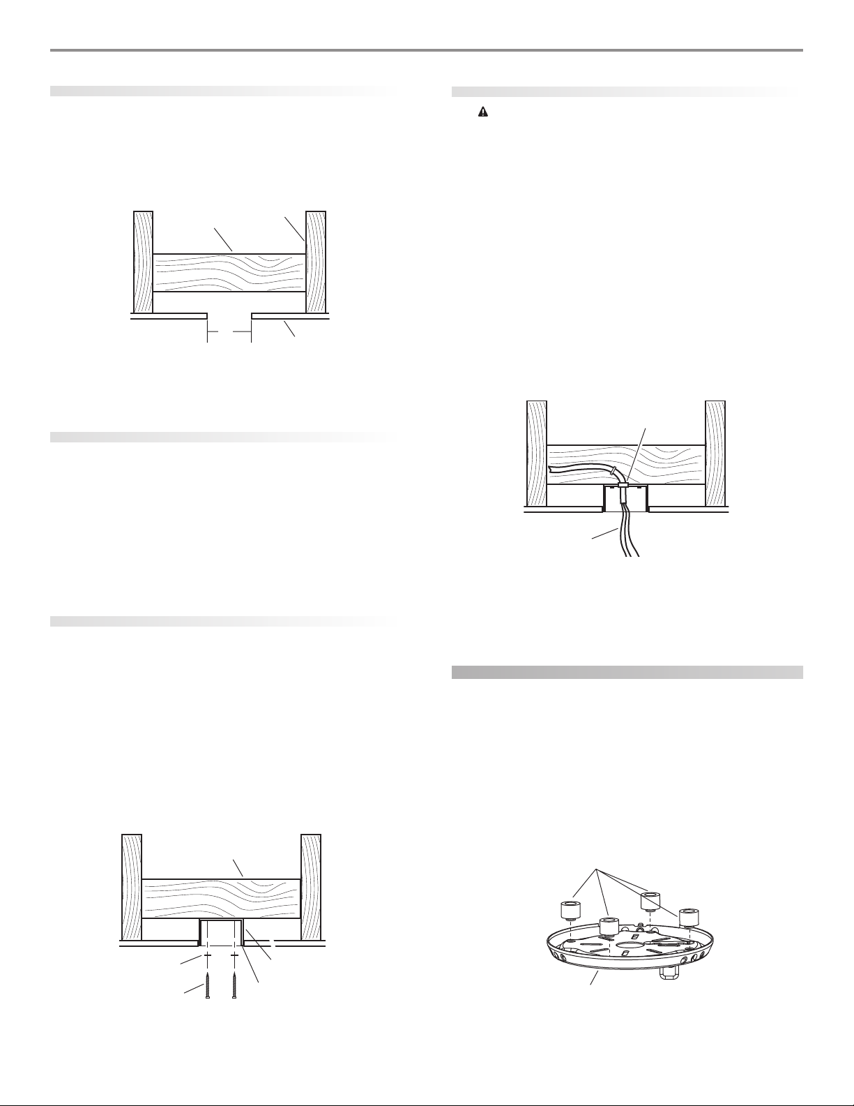
If there is not an adequate ceiling joist available, do the following:
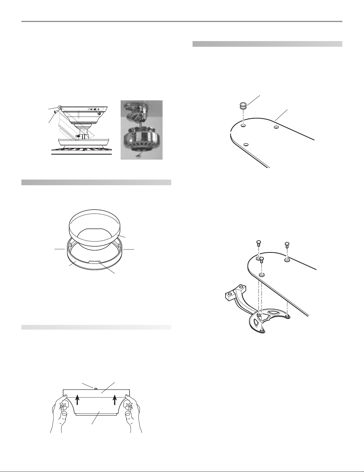
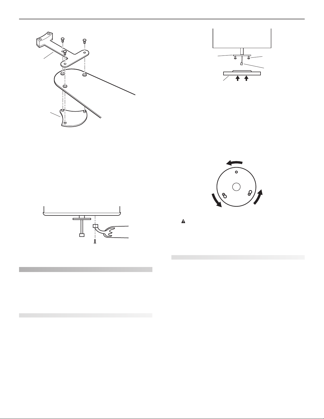
1. Attach a 2" x 4" support brace between two joists. The support brace must allow the bottom of the outlet box to be recessed a minimum of 1/16" into the ceiling. See Figure 7.
2. Check the support brace to ensure it will support the full weight
of the fan and light kit.
installing the outlet box
1. Obtain a UL-approved octagonal 4" x 1-1/2" outlet box, plus
two #8 x 1-1/2" wood screws and washers, available from any
hardware store or electrical supply house.
2. Orient the outlet box so that both the inner and outer holes in
the box align with the joist or support brace.
3. Drill pilot holes no larger than the minor diameter of the wood
screws (5/64") through the inner holes of the outlet box.
4. Attach the outlet box directly to the support brace or joist
with two #8 x 1-1/2" wood screws and washers. The bottom of
the outlet box must be recessed a minimum of 1/16" into the
ceiling as shown in Figure 7.
Support Brace
preparing the wiring
CC
AA
UU
TT
II
OO
N: AN: A
ll wll w
irir
inin
g mug mu
ss
t bt b
e in ae in a
cc
cc
oo
rr
dd
aa
nn
cc
e we w
ii
tt
c
e w
cc
e we w
A 70. IA 70. I
A 70. I
A 70. IA 70. I
uu
aa
lili
a
li
uu
aa
lili
h nh n
i
t
h n
ii
tt
h nh n
f yf y
oo
f y
o
f yf y
oo
ff
ii
ee
d ed e
ll
ee
f
i
e
d e
l
e
ff
ii
ee
d ed e
ll
ee
tt
t
tt
aa
a
aa
tt
t
tt
C
CC
ii
oo
i
o
ii
oo
rr
e une un
r
e un
rr
e une un
rr
ii
cc
r
i
c
rr
ii
cc
A
U
T
I
O
N: A
ll w
ir
in
g mu
s
t b
e in a
c
c
o
r
d
a
AA
UU
TT
II
OO
N: AN: A
ll wll w
irir
inin
g mug mu
ss
t bt b
e in ae in a
nn
aa
l al a
nn
d ld l
oo
cc
aa
l el e
ll
ee
cc
tt
rr
ii
cc
aa
l cl c
oo
dd
ee
s as a
nn
n
a
l a
n
d l
o
c
a
l e
l
e
c
t
r
i
c
a
l c
nn
aa
l al a
nn
d ld l
oo
cc
aa
l el e
ll
ee
cc
ff
aa
mm
iliili
aa
r wr w
ii
tt
f
a
m
ili
ff
aa
mm
ii
aa
nn
..
i
a
n
.
ii
aa
nn
..
h wh w
a
r w
i
t
h w
iliili
aa
r wr w
ii
tt
h wh w
o
tt
rr
ii
cc
aa
l cl c
oo
irir
inin
gg
, y, y
ir
in
g
, y
irir
inin
gg
, y, y
d Ad A
d
e
s a
n
d A
dd
ee
s as a
nn
d Ad A
oo
u su s
hh
oo
ulul
u s
u su s
d ud u
h
o
ul
d u
hh
oo
ulul
d ud u
o
oo
n
cc
cc
oo
rr
dd
aa
nn
NN
SS
I/NI/N
FF
PP
N
S
I/N
F
P
NN
SS
I/NI/N
FF
PP
ss
e a qe a q
s
e a q
u
ss
e a qe a q
1. Make sure the circuit breakers to the fan supply line leads and
associated wall switch location are turned off. If you cannot
lock the circuit breakers in the off position, securely fasten a
prominent warning device, such as a tag, to the service panel.
2. Thread the fan supply line through the outlet box so that the
fan supply line extends at least 6" beyond the box as shown in
Figure 8.
3. Attach the fan supply line to the outlet box with an approved
connector, available at any hardware store or electrical supply
house. Refer to Figure 8.
4. Make certain the wiring meets all national and local standards
and ANSI/NFPA 70.
Approved
Connector
Wire Leads
FF
ii
gg
urur
e 8 - Pre 8 - Pr
ee
pp
aa
rr
inin
g tg t
hh
e we w
irir
inin
F
i
g
ur
e 8 - Pr
e
p
a
r
in
g t
FF
ii
gg
urur
e 8 - Pre 8 - Pr
ee
h
pp
aa
rr
inin
g tg t
hh
e w
e we w
gg
ir
in
g
irir
inin
gg
You have now successfully prepared your ceiling fan site. For instructions on how to install your ceiling fan, continue with the
ss
tt
aa
llinllin
g tg t
hh
e ce c
ee
ilinilin
g pg p
ll
aa
tt
s
t
a
llin
g t
h
e c
e
ss
tt
aa
llinllin
g tg t
ilin
hh
e ce c
ee
ilinilin
g p
g pg p
ee
l
a
t
e section.
ll
aa
tt
ee
in-in-
in-
in-in-
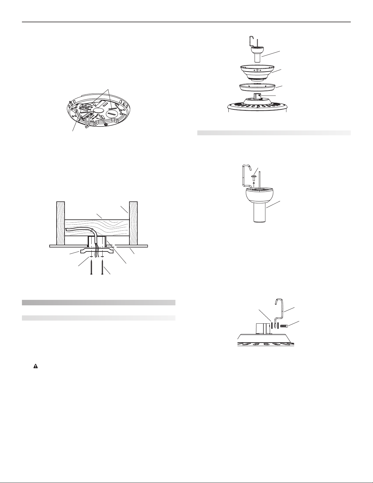
installing the ceiling plate
1. Drill two pilot holes into the wood support structure through
the outermost holes on the outlet box. The pilot holes should
be 9/64" in diameter.
2. Thread the lead wires from the outlet box through the hole in
the middle of the ceiling plate.
3. Your fan comes with four neoprene noise isolators. Position
the isolators between the ceiling plate and ceiling by inserting
the raised areas on each isolator into the holes in the ceiling
plate. Refer to Figure 9.
Isolators
a-a-
a-
a-a-
c
uu
u
uu
cc
--
-
cc
--
Washer
Wood Screw
FF
ii
gg
urur
e 7 - Ie 7 - I
nn
ss
tt
aa
F
i
g
ur
e 7 - I
FF
ii
gg
urur
e 7 - Ie 7 - I
41814-01 01/14/2003 © 2003 Hunter Fan Company
llinllin
n
s
t
a
llin
nn
ss
tt
aa
llinllin
g tg t
g t
g tg t
hh
h
hh
Outlet Box
1/16” Recess
e oe o
uu
tt
ll
ee
t bt b
e o
u
t
l
e
t b
e oe o
uu
tt
ll
ee
t bt b
Ceiling Plate
FF
ii
gg
urur
e 9 - Ie 9 - I
nn
ss
ee
rr
tt
inin
g tg t
hh
e ie i
ss
oo
ll
aa
tt
oo
rr
s ins in
tt
o to t
hh
e ce c
ee
ilinilin
g pg p
ll
aa
tt
F
i
g
ur
e 9 - I
n
s
e
r
t
in
g t
h
e i
s
o
l
a
t
o
r
s in
t
o t
h
e c
e
FF
ii
gg
urur
e 9 - Ie 9 - I
nn
ss
ee
rr
tt
inin
g tg t
hh
e ie i
ss
oo
ll
aa
tt
oo
rr
s ins in
oo
xx
o
x
oo
xx
tt
o to t
ilin
hh
e ce c
ee
ilinilin
g p
g pg p
ee
l
a
t
e
ll
aa
tt
ee
Page 5
4. Align the slotted holes (refer to Figure 10) in the ceiling plate
with the pilot holes in the wood support structure. Note: The
isolation pads should be flush against the ceiling.
For Angled Ceilings: Be sure to orient the ceiling plate so that
the arrows on the ceiling plate are pointing towards the ceiling
peak. Refer to Figure 10.
Hanger Ball/
Downrod Assembly
Canopy
55
5
55
Slots
Arrows for Orienting
on Angled Ceiling
FF
ii
gg
urur
e 10 - Le 10 - L
oo
cc
aa
tt
inin
g tg t
hh
e se s
ll
oo
tt
tt
ee
d hd h
oo
ll
ee
s ts t
o uo u
ss
F
FF
i
g
ii
gg
ur
e 10 - L
urur
e 10 - Le 10 - L
o
c
a
t
in
g t
h
e s
l
o
t
t
e
d h
o
oo
cc
aa
tt
inin
g tg t
hh
e se s
ll
oo
l
tt
tt
ee
d hd h
oo
ll
ee
e
s t
o u
s
e
ee
s ts t
o uo u
ss
ee
5. Place a flat washer on each of the two 3" screws and pass the
screws through the slotted holes in the ceiling plate as shown
in Figure 11.
6. Tighten the screws into the 9/64" pilot holes; do not use lubricants on the screws. Do not overtighten.
Ceiling Joist
2 x 4 Brace
Ceiling Plate
Flat Washer
FF
ii
gg
urur
e 11 - Ie 11 - I
F
i
g
ur
e 11 - I
FF
ii
gg
urur
e 11 - Ie 11 - I
nn
ss
tt
aa
llinllin
g tg t
hh
llin
llinllin
g t
g tg t
e ce c
h
e c
hh
e ce c
n
s
t
a
nn
ss
tt
aa
Ceiling
Outlet Box
3” Wood Screw
ee
ilinilin
g pg p
ll
aa
e
ilin
g p
l
a
ee
ilinilin
g pg p
ll
aa
tt
ee
t
e
tt
ee
Canopy Trim Ring
Set Screw
FF
ii
gg
urur
e 12 - Ae 12 - A
ss
ss
ee
mbmb
linlin
g tg t
hh
e de d
oo
ww
nrnr
oo
F
FF
i
g
ii
gg
ur
e 12 - A
urur
e 12 - Ae 12 - A
s
s
e
mb
lin
g t
h
linlin
g tg t
e d
hh
e de d
ss
ss
ee
mbmb
dd
o
w
nr
o
d
oo
ww
nrnr
oo
dd
assembling the fan for a low ceiling
1. Remove the screw on the hanger ball to disassemble it from
the downrod as shown in Figure 13.
Screw on the Hanger Ball
Hanger Ball/
Downrod
Assembly
FF
ii
gg
urur
e 13 - Re 13 - R
ee
mm
oo
vv
inin
g tg t
hh
e se s
cc
rr
ee
w fw f
rr
oo
m tm t
hh
e he h
aa
nn
gg
ee
r br b
aa
F
i
g
ur
e 13 - R
e
m
o
v
in
g t
h
e s
c
r
e
w f
r
o
m t
h
e h
FF
ii
gg
urur
e 13 - Re 13 - R
ee
mm
oo
vv
inin
g tg t
hh
e se s
cc
rr
ee
w fw f
rr
oo
m tm t
a
hh
e he h
aa
2. Remove the hook from the assembly.
3. Completely remove the set screw (identified in Figure 12) from
the fan adapter.
4. Put the set screw, previously removed, through the two black
neoprene washers and the hook as shown in Figure 14. Hook
must be installed in same orientation as shown in Figure 14.
llll
n
g
e
r b
a
ll
nn
gg
ee
r br b
aa
llll
assembling the fan
assembling the fan for a standard or angled ceiling
Black Neoprene
Washer
Hook
Set Screw
1. Insert the downrod through the canopy and canopy trim ring
as shown in Figure 12. Feed wires from the fan through the
downrod.
2. Screw the downrod into the fan assembly until tight. IMPOR-
FF
ii
gg
urur
e 14 - Ae 14 - A
ss
ss
ee
mbmb
linlin
g tg t
hh
e se s
ee
t st s
cc
rr
ee
w fw f
oo
r lr l
oo
w pw p
rr
oo
ff
ilil
TANT! Tighten downrod set screw as shown in Figure 12.
CC
AA
UU
TT
II
OO
N: TN: T
hh
e de d
oo
ww
nrnr
oo
d hd h
aa
s a ss a s
pp
ee
cc
ii
aa
g; tg; t
g; t
g; tg; t
nn
n
nn
l cl c
p
e
c
i
a
l c
pp
ee
cc
ii
aa
l cl c
hh
e ce c
oo
h
e c
o
hh
e ce c
oo
cc
e ae a
ss
ss
ee
c
e a
s
s
e
cc
e ae a
ss
ss
ee
C
A
U
T
I
O
CC
tt
hrhr
ee
t
hr
e
tt
hrhr
ee
tt
hh
e de d
t
h
e d
tt
hh
e de d
rr
ee
mm
r
e
m
rr
ee
mm
N: T
AA
UU
TT
II
OO
N: TN: T
aa
dd
ss
. D. D
o no n
a
d
s
. D
o n
aa
dd
ss
. D. D
o no n
oo
ww
nrnr
oo
d fd f
o
w
nr
o
d f
oo
ww
nrnr
oo
d fd f
oo
vv
e te t
hh
e de d
e t
e te t
oo
h
e d
o
hh
e de d
oo
o
v
oo
vv
3. Continue to the
oo
o
oo
t rt r
t r
t rt r
rr
oo
r
o
rr
oo
ww
w
ww
hh
h
hh
h
e d
hh
e de d
ee
mm
e
m
ee
mm
m unm un
m un
m unm un
nrnr
oo
nr
o
nrnr
oo
aa
nn
a
n
aa
nn
o
w
nr
o
d h
a
oo
hh
h
hh
rr
ee
r
e
rr
ee
hh
h
hh
w
ww
ww
e fe f
e f
e fe f
d hd h
ii
s cs c
i
s c
ii
s cs c
inin
in
inin
aa
a
aa
s a s
aa
s a ss a s
oo
aa
tt
inin
o
a
t
in
oo
aa
tt
inin
gg
. O. O
g
. O
gg
. O. O
nn
n section.
nn
oo
ww
nrnr
oo
vv
e te t
o
v
e t
oo
vv
e te t
ss
cc
s
c
ss
cc
d.d.
d.
d.d.
gg
inin
g tg t
g
in
g t
gg
inin
g tg t
oo
o
oo
aa
tt
a
t
aa
tt
mbmb
mb
mbmb
F
i
g
ur
e 14 - A
s
s
e
mb
lin
g t
h
e s
e
t s
c
r
e
w f
o
r l
FF
ii
gg
urur
e 14 - Ae 14 - A
ss
ss
ee
mbmb
linlin
g tg t
hh
e se s
ee
t st s
cc
rr
aa
ss
ss
ee
mbmb
ll
yy
a
s
s
e
mb
l
y
aa
ss
ss
ee
mbmb
ll
aa
tt
inin
g og o
n tn t
hh
a
t
in
g o
aa
tt
inin
g og o
inin
g pg p
in
g p
inin
g pg p
ll
ee
d, dd, d
l
e
d, d
ll
ee
d, dd, d
ee
n t
h
e
n tn t
hh
ee
rr
ee
vv
ee
nn
tt
ss
r
e
v
e
n
t
s
rr
ee
vv
ee
nn
tt
ss
o no n
oo
tt
o n
o
t
o no n
oo
tt
5. Reassemble the set screw to the adapter as shown in Figure 14.
NOTE: The rubber washers should be tight enough to keep
yy
o
ee
w fw f
oo
r lr l
oo
the hook standing straight up, but the set screw should not be
completely tighten as to keep the hook from being able to
w p
w pw p
ee
r
o
f
il
e
rr
oo
ff
ilil
ee
swing.
© 2003 Hunter Fan Company 41814-01 01/14/2003
Page 6
66
6
66
6. Place the canopy trim ring then the canopy over the adapter
as shown in Figure 15.
7. Place the low profile washer (lip up) into the canopy as shown
in Figure 15 fitting the notch in the low profile washer over the
adapter set screw and hook.
Tab Hole
FF
ii
gg
urur
F
i
g
ur
FF
ii
gg
urur
e 15 - Ae 15 - A
e 15 - A
e 15 - Ae 15 - A
ss
ss
ee
mbmb
linlin
s
ss
g cg c
s
e
mb
lin
g c
ss
ee
mbmb
linlin
g cg c
Low Profile Washer
aa
nn
oo
pp
y fy f
oo
a
n
o
p
y f
o
aa
nn
oo
pp
y fy f
oo
Canopy
Canopy Trim Ring
Arrow on the
Low Profile
Wash er
r lr l
oo
w pw p
rr
r l
o
w p
r
r lr l
oo
w pw p
rr
oo
ff
ilil
e me m
oo
unun
tt
inin
o
f
il
e m
oo
ff
ilil
e me m
gg
o
un
t
in
g
oo
unun
tt
inin
gg
8. Rotate the canopy until the arrow on the low profile washer
aligns with the tab hole on the canopy as shown in Figure 15.
9. Align the holes in the low profile washer with the holes in the
adapter and assemble securely with the three #8-32 x 1” screws.
hanging the fan
1. Raise the fan and place the hook through the loop on the ceiling plate as shown in Figure 16. Use the note and arrow engraved in the ceiling plate to assist in determining the direction to assemble.
WW
AA
RR
NN
II
NN
G: FG: F
aa
n mn m
aa
y fy f
aa
ll ill i
f nf n
oo
t at a
ss
ss
ee
mbmb
ll
ee
d ad a
s dirs dir
ee
cc
tt
ee
W
A
R
N
I
N
G: F
a
n m
a
y f
a
ll i
f n
o
t a
s
s
e
mb
l
e
d a
WW
AA
RR
NN
II
NN
G: FG: F
aa
n mn m
aa
y fy f
aa
ll ill i
f nf n
oo
t at a
ss
ss
ee
mbmb
tt
hh
ee
ss
e ine in
ss
tt
aa
llll
aa
tt
ii
oo
n inn in
ss
tt
rr
uu
cc
tt
ii
oo
nn
ss
t
h
e
s
e in
s
t
a
ll
a
t
i
o
n in
s
t
tt
hh
ee
ss
e ine in
ss
tt
aa
llll
aa
tt
ii
oo
Hook
n inn in
r
ss
tt
rr
..
u
c
t
i
o
n
s
.
uu
cc
tt
ii
oo
nn
ss
..
Loop
s dir
ll
ee
d ad a
s dirs dir
d ind in
e
c
t
e
d in
ee
cc
tt
ee
d ind in
• control the light with one wall switch and the fan with
another (two wall switches required).
Use connection 2, as described in Figure 17, if there is no separate wall switch power wire for the light fixture.
NOTE: Wall switches not included.
3. Connect the wires as shown in Figure 17. To connect the wires,
twist the bare metal leads together. Place a wire nut over the
intertwined length of wire and twist clockwise until tight as.
CC
AA
UU
TT
II
OO
N: BN: B
e se s
urur
e ne n
o bo b
aa
rr
e we w
irir
e oe o
r wr w
irir
e se s
tt
rr
aa
nn
dd
s as a
rr
e ve v
C
A
U
T
I
O
CC
ibib
ll
e ae a
ib
l
e a
ibib
ll
e ae a
AA
ll wll w
A
ll w
AA
ll wll w
ee
ll
ee
cc
e
l
e
c
ee
ll
ee
cc
ww
ii
tt
h wh w
w
i
t
h w
ww
ii
tt
h wh w
2 x 4 Brace
Approved
Connectors
Green Ground Wire from
Hanger Pipe (not present
with flush mounting
option)
N: B
AA
UU
TT
II
OO
N: BN: B
ff
tt
ee
r mr m
aa
kk
f
t
ff
tt
irir
ir
irir
tt
rr
ii
t
r
i
c
tt
rr
ii
inin
e
r m
a
k
in
ee
r mr m
aa
kk
inin
inin
g mug mu
ss
in
g mu
s
inin
g mug mu
ss
cc
aa
l cl c
oo
dd
ee
a
l c
o
d
e
cc
aa
l cl c
oo
dd
ee
irir
inin
gg
, y, y
oo
ir
in
g
, y
o
irir
inin
gg
, y, y
oo
Wall Switch Wire for Separate
Control of Light Fixture
Power
Wires
in
Ceiling
e s
ur
e n
e se s
urur
e ne n
g cg c
oo
nnnn
ee
g c
o
nn
e
g cg c
oo
nnnn
ee
t bt b
e in ae in a
t b
e in a
t bt b
e in ae in a
s as a
nn
d Ad A
n
nn
hh
h
hh
d A
d Ad A
oo
ulul
o
ul
oo
ulul
NN
N
NN
d ud u
d u
d ud u
s a
s as a
u su s
u s
u su s
Black
White
Bare or Green
o b
o bo b
cc
c
cc
cc
c
cc
tt
t
tt
cc
c
cc
SS
S
SS
ii
i
ii
oo
o
oo
I/NI/N
I/N
I/NI/N
ss
s
ss
White
oo
o
oo
a
r
e w
aa
rr
e we w
nn
ss
n
s
nn
ss
rr
dd
aa
r
d
a
rr
dd
aa
FF
F
FF
e a qe a q
e a q
e a qe a q
2
Black
ir
e o
irir
e oe o
..
.
..
nn
cc
e we w
n
c
e w
nn
cc
e we w
PP
A 70. IA 70. I
P
A 70. I
PP
A 70. IA 70. I
uu
aa
lili
u
a
li
uu
aa
lili
(Note: Wall
switch must be
acceptable as a
general-use
switch.)
1
Blk/Wht
3 Wires
from Fan
r w
ir
e s
t
r
a
n
e se s
tt
rr
aa
nn
aa
tt
ii
oo
nn
aa
a
t
i
o
n
a
aa
tt
ii
oo
nn
aa
u au a
rr
e une un
u a
r
e un
u au a
rr
e une un
ll
ee
cc
tt
rr
ii
cc
l
e
c
t
r
i
c
ll
ee
cc
tt
rr
ii
cc
Ceiling Plate
ii
i
ii
l al a
l a
l al a
aa
a
aa
d
dd
r wr w
irir
ii
tt
h nh n
i
t
h n
ii
tt
h nh n
f yf y
oo
f y
o
f yf y
oo
ff
ii
ee
d ed e
f
i
e
d e
ff
ii
ee
d ed e
Outlet Box
Connections:
1. Connect Blk/Wht
wire from the fan to the
wall switch for separate
control of the light
fixture, or
2. Connect Blk/Wht
wire from the fan to the
ceiling black wire if there
is no separate wall
switch wire for the light
fixture.
s a
s as a
nn
n
nn
ii
r
e v
i
rr
e ve v
ii
nn
d ld l
oo
cc
n
d l
o
c
nn
d ld l
oo
cc
ff
aa
mm
iliili
f
a
m
ili
a
ff
aa
mm
iliili
..
.
..
ss
--
s
-
ss
--
aa
ll
a
l
aa
ll
aa
rr
r
aa
rr
FF
ii
gg
urur
F
i
FF
ii
g
ur
gg
urur
e 17 - We 17 - W
e 17 - W
e 17 - We 17 - W
irir
inin
g tg t
hh
e fe f
aa
g t
g tg t
nn
h
e f
a
n
hh
e fe f
aa
nn
ir
in
irir
inin
installing the canopy
1. Rotate the fan 180º clockwise from the initial position when
hanging the fan. The arrows on the hanger ball and on the
FF
ii
gg
urur
e 16 - Hae 16 - Ha
F
i
g
ur
e 16 - Ha
FF
ii
gg
urur
e 16 - Hae 16 - Ha
wiring the fan
1. Disconnect the power by turning off the circuit breakers to
the outlet box and associated wall switch location.
2. You can use either one or two wall switches to control the fan
and/or lights separately. Use connection 1, as described in Figure 17, to
• control the light with a wall switch and the fan with a pull
chain (one wall switch required),
• control the light with a pull chain and the fan with a wall
switch (one wall switch required), or
41814-01 01/14/2003 © 2003 Hunter Fan Company
nn
gg
inin
g tg t
hh
e fe f
aa
g t
g tg t
nn
h
e f
a
n
hh
e fe f
aa
nn
ceiling plate should be pointing in the same direction and
n
g
in
nn
gg
inin
should be pointing towards the tab hole on the canopy. Refer
to Figure 18.
FF
ii
gg
urur
e 18 - Re 18 - R
oo
tt
aa
tt
inin
g tg t
hh
e fe f
aa
F
FF
i
g
ii
gg
ur
e 18 - R
urur
e 18 - Re 18 - R
o
t
a
t
in
oo
tt
aa
tt
inin
g t
g tg t
nn
h
e f
a
n
hh
e fe f
aa
nn
Page 7
For Flush Mounting: The arrows on the low profile washer and
on the ceiling plate should be pointing in the same direction
and should be pointing towards the tab hole on the canopy.
2. Hook the tab hole over the tab on the ceiling plate as shown in
Figure 19.
3. Raise the canopy, be sure the holes in the canopy and the ceiling plate are aligned, and loosely assemble the canopy screws
one at a time. When all three screws are assembled, securely
tighten all three canopy screws. Refer to Figure 19.
77
7
77
assembling the blades
Hunter fans use several styles of fan blade irons (brackets that hold
the blade to the fan).
1. Your fan may include blade grommets. If your fan has grommets, insert them by hand into the holes on the blades as shown
in Figure 22.
Grommet
Tab Hole
and Tab
Canopy
Screw
FF
ii
gg
urur
e 19 - Ie 19 - I
nn
ss
tt
aa
llinllin
g tg t
hh
e ce c
aa
nn
oo
pp
F
i
g
ur
e 19 - I
n
s
t
a
llin
g t
FF
ii
gg
urur
e 19 - Ie 19 - I
nn
ss
h
tt
aa
llinllin
g tg t
hh
e c
e ce c
yy
a
n
o
p
y
aa
nn
oo
pp
yy
installing the canopy trim ring
1. To easily install the canopy trim ring, locate the two tabs on
the canopy trim ring. See Figure 20.
Canopy
Press Here when
Removing
Canopy
Trim Ring
Press Here when
Removing
Tab
Fan Blade
FF
ii
gg
urur
e 22 - Ie 22 - I
nn
ss
ee
rr
tt
inin
g tg t
hh
e ge g
rr
oo
mmmm
ee
tt
s ins in
tt
o to t
hh
e fe f
aa
n bn b
ll
aa
dd
ee
F
i
g
ur
e 22 - I
n
s
e
r
t
in
g t
h
e g
r
o
mm
e
t
s in
t
o t
h
e f
FF
ii
gg
urur
e 22 - Ie 22 - I
nn
ss
ee
rr
tt
inin
g tg t
hh
e ge g
rr
oo
mmmm
ee
tt
s ins in
a
tt
o to t
hh
e fe f
aa
n b
n bn b
ss
l
a
d
e
s
ll
aa
dd
ee
ss
2. Attach each blade to blade iron using three blade assembly
screws as shown in Figure 23. Some fans feature a decorative
medallion as well as a blade iron. Insert the assembly screws
into the blade iron, through the blade and into the medallion,
with the blade sandwiched between the blade iron and medallion as shown in Figure 24.
FF
ii
gg
urur
e 20 - Ce 20 - C
aa
nn
oo
pp
y ty t
rr
im rim r
inin
F
FF
i
g
ii
gg
ur
e 20 - C
urur
e 20 - Ce 20 - C
a
n
o
p
y t
aa
nn
oo
pp
y ty t
r
im r
rr
im rim r
gg
in
g
inin
gg
2. Take both hands and push the canopy trim ring up to the top
of the canopy. See Figure 20.
3. The canopy trim ring will snap and lock into place on the
canopy.
removing the canopy trim ring
1. Locate the tab indicators, small bumps on top of tabs. Refer to
Figure 21.
2. To remove the canopy trim ring, press firmly on opposite sides
of the ring towards the canopy as shown in Figure 21. The tabs
will flex out releasing the trim ring from the canopy.
FF
ii
gg
urur
F
i
g
ur
FF
ii
gg
urur
Tab Indicator
e 21 - Re 21 - R
e 21 - R
e 21 - Re 21 - R
ee
mm
e
m
ee
mm
Canopy
oo
vv
inin
o
v
in
oo
vv
inin
Canopy Trim Ring
g tg t
hh
e ce c
aa
nn
oo
pp
e c
e ce c
y ty t
a
n
o
p
y t
aa
nn
oo
pp
y ty t
g t
g tg t
h
hh
rr
im rim r
r
im r
rr
im rim r
inin
gg
in
g
inin
gg
FF
F
FF
ii
gg
urur
i
g
ur
ii
gg
urur
e 23 - Ae 23 - A
e 23 - A
e 23 - Ae 23 - A
tt
tt
aa
cc
hh
inin
g tg t
hh
e be b
ll
aa
dd
e te t
o to t
hh
e be b
ll
aa
dd
e ire ir
oo
t
t
a
c
h
in
g t
h
e b
l
a
d
e t
o t
h
tt
tt
aa
cc
hh
inin
g tg t
hh
e be b
ll
aa
e b
dd
e te t
o to t
hh
e be b
nn
l
a
d
e ir
o
n
ll
aa
dd
e ire ir
oo
nn
© 2003 Hunter Fan Company 41814-01 01/14/2003
Page 8
88
8
88
Blade Iron
Medallion
FF
ii
gg
urur
e 24 - Ae 24 - A
tt
tt
aa
cc
hh
inin
g tg t
hh
e be b
ll
aa
dd
e te t
o to t
hh
e be b
ll
aa
dd
e ire ir
oo
n an a
nn
F
FF
i
g
ur
ii
gg
e 24 - A
urur
e 24 - Ae 24 - A
t
t
a
c
h
in
g t
h
e b
l
a
d
e t
o t
h
e b
l
a
d
tt
tt
aa
cc
hh
inin
g tg t
hh
e be b
ll
aa
dd
e te t
o to t
mm
ee
dd
aa
llilli
oo
m
mm
nn
e
d
a
lli
o
n
ee
dd
aa
llilli
oo
nn
e ir
hh
e be b
ll
aa
dd
e ire ir
dd
o
n a
n
d
oo
n an a
nn
dd
If you used grommets, the blades may appear slightly loose
after screws are tightened. This is normal.
3. Remove the blade mounting screws and rubber shipping
bumpers from the motor.
4. For each blade, insert one blade mounting screw through the
blade iron as shown in Figure 25, and attach lightly to the fan.
Insert the second blade mounting screw, then securely tighten
both mounting screws.
Switch Housing
Mounting Plate
FF
ii
gg
urur
e 26 - Ae 26 - A
F
i
g
ur
e 26 - A
FF
ii
gg
urur
e 26 - Ae 26 - A
Upper Switch
Housing
tt
tt
aa
cc
hh
inin
t
t
a
c
h
in
tt
tt
aa
cc
hh
inin
g tg t
hh
e upe up
pp
ee
h
hh
unun
un
unun
e up
e upe up
tt
inin
t
in
tt
inin
p
pp
g pg p
g p
g pg p
r sr s
e
r s
ee
r sr s
ll
aa
l
a
ll
aa
g t
g tg t
mm
oo
m
o
mm
oo
Housing
Assembly
Screw
Upper Plug
Connector
ww
ii
tt
cc
h hh h
oo
uu
sinsin
g tg t
o to t
hh
w
i
t
c
h h
o
u
ww
ii
tt
ee
t
e
tt
ee
sin
tt
cc
h hh h
oo
uu
sinsin
g t
g tg t
o t
o to t
ee
h
e
hh
ee
3. Align the keyhole slots in the upper switch housing with the
housing assembly screws installed previously.
4. Turn the upper switch housing counterclockwise until the
housing assembly screws are firmly situated in the narrow end
of the keyhole slots as shown in Figure 27. Install the one remaining #6-32 x 3/8" housing assembly screw into the third
hole in the upper switch housing. Tighten all three screws firmly.
FF
ii
gg
urur
e 25 - Ae 25 - A
tt
tt
aa
cc
hh
inin
g tg t
hh
e be b
ll
aa
dd
e ire ir
oo
n tn t
o to t
hh
e fe f
aa
F
FF
i
g
ii
gg
ur
e 25 - A
urur
e 25 - Ae 25 - A
t
t
a
c
h
in
g t
h
e b
l
a
d
e ir
o
tt
tt
aa
cc
hh
inin
g tg t
hh
e be b
n t
ll
aa
dd
e ire ir
oo
n tn t
o t
o to t
nn
h
e f
a
n
hh
e fe f
aa
nn
installing the light fixture
You can install with or without the light fixture. If you want to
inin
ss
tt
aa
llinllin
g wg w
ii
tt
hh
oo
uu
t tt t
install without the light fixture, skip to the
lili
gg
hh
t ft f
ii
xx
tt
urur
t f
t ft f
WW
W
WW
mm
m
mm
i
x
t
ii
xx
tt
AA
RR
A
R
AA
RR
oo
dd
o
d
oo
dd
ee
ur
e section.
urur
ee
NN
II
NN
N
I
N
NN
II
NN
ee
l.l.
e
l.
ee
l.l.
G: UsG: Us
G: Us
G: UsG: Us
e oe o
e o
e oe o
nlnl
nl
nlnl
y ty t
y t
y ty t
hh
e se s
upup
h
e s
up
hh
e se s
upup
li
g
h
lili
gg
hh
in
s
t
a
llin
g w
llinllin
ii
xx
i
x
ii
xx
i
g wg w
ii
tt
urur
e fe f
oo
t
ur
e f
o
tt
urur
e fe f
oo
inin
ss
tt
aa
pp
lili
ee
d lid li
gg
hh
e
ee
d li
d lid li
t ft f
g
h
t f
gg
hh
t ft f
p
li
pp
lili
attaching the upper switch housing
1. Partially install two #6-32 x 3/8" housing assembly screws into
the switch housing mounting plate as shown in Figure 26.
2. Feed the upper plug connector through the center opening of
the upper switch housing. See Figure 26.
hh
t
h
o
u
t t
h
tt
hh
oo
uu
t tt t
hh
r tr t
hh
ii
s fs f
aa
r t
h
i
s f
a
r tr t
hh
ii
s fs f
aa
FF
ii
gg
urur
cc
c
cc
urur
ur
urur
ss
s
ss
ff
f
ff
i
ur
ee
e
ee
ii
ii
urur
urur
xx
x
xx
CC
C
CC
ee
e
ee
e te t
e t
e te t
mbmb
mb
mbmb
tt
urur
t
ur
tt
urur
AA
A
AA
ll
y ay a
l
y a
ll
y ay a
o po p
o p
o po p
F
FF
U
UU
UU
ll
l
ll
y sy s
y s
y sy s
e fe f
e f
e fe f
i
g
ur
ii
gg
urur
TT
T
TT
tt
t
tt
aa
a
aa
e 27 - Me 27 - M
e 27 - M
e 27 - Me 27 - M
II
OO
I
O
II
OO
tt
aa
t
a
tt
aa
rr
oo
r
o
rr
oo
cc
rr
c
r
cc
rr
llinllin
llin
llinllin
N: MN: M
N: M
N: MN: M
cc
hh
ee
c
h
e
cc
hh
ee
pp
ee
rr
p
e
r
pp
ee
rr
ee
ww
s cs c
e
w
s c
ee
ww
s cs c
gg
g
.
gg
d td t
d t
d td t
ll
l
ll
..
..
y ay a
y a
y ay a
oo
o
oo
aa
a
aa
o to t
o t
o to t
ulul
ul
ulul
oo
unun
tt
inin
g tg t
hh
e upe up
pp
ee
r sr s
ww
ii
tt
cc
h hh h
oo
uu
sinsin
o
un
t
in
g t
h
e up
p
e
r s
w
i
t
c
oo
unun
tt
inin
g tg t
hh
e upe up
pp
kk
e se s
urur
e te t
hh
e se s
e se s
cc
c
cc
ur
urur
ww
w
ww
h ah a
h a
h ah a
ee
ss
e
s
ee
ss
e t
e te t
ii
i
ii
ulul
ul
ulul
n
h
hh
tt
cc
h hh h
t
c
h h
tt
cc
h hh h
nn
d td t
d t
nn
d td t
t in tt in t
t in t
t in tt in t
e upe up
e up
e upe up
oo
o
oo
ii
gg
i
g
ii
gg
hh
h
hh
uu
u
uu
hh
h
hh
k
e s
kk
e se s
hh
h
e s
hh
tt
tt
aa
t
t
a
tt
tt
aa
d rd r
d r
d rd r
ee
p
tt
t
tt
e se s
e s
e se s
r sr s
pp
pp
sinsin
sin
sinsin
ee
e
ee
ee
e
ee
n an a
n a
n an a
ww
w
ww
ww
r sr s
r s
r sr s
g mg m
g m
g mg m
h h
ii
tt
cc
h hh h
ww
ii
w
i
ww
ii
oo
o
oo
ll tll t
ll t
ll tll t
ii
tt
cc
h hh h
i
t
c
h h
ii
tt
cc
h hh h
gg
o
u
sin
g
oo
uu
sinsin
gg
tt
cc
h hh h
oo
uu
sinsin
g ig i
s ss s
t
c
h h
o
u
cc
unun
un
unun
hrhr
hr
hrhr
h hh h
oo
o
oo
ee
e
ee
tt
t
tt
uu
u
uu
oo
inin
in
inin
e he h
e h
e he h
sinsin
sin
sinsin
uu
g pg p
g p
g pg p
sin
sinsin
oo
o
oo
g ag a
g a
g ag a
tt
e-e-
g i
s s
e-
g ig i
s ss s
e-e-
ll
aa
tt
ee
. F. F
aa
il-il-
l
a
t
e
. F
a
il-
ll
aa
tt
ee
. F. F
aa
il-il-
uu
sinsin
g ag a
ss
sin
sinsin
nn
n
nn
d lid li
d li
d lid li
g a
g ag a
--
s
-
ss
--
gg
hh
tt
g
h
t
gg
hh
tt
u
uu
attaching the light fixture
Refer to Figure 28.
1. Remove the plug cap from the lower switch housing.
NN
oo
tt
e:e:
N
o
t
e: Do not discard the plug cap. You will need this if you
NN
oo
tt
ee
e
ee
2. Remove top housing from the light fixture by loosening the
nn
n
nn
3. Locate the two wires in the lower switch housing lab eled “Con-
4. Place these wires into the hole in the center of the top housing
5. Screw the fixture into the lower switch housing. Thread the
6. Locate the white wire and the black wire coming from the light
e:e:
remove the light fixture in the future.
three screws and turning counter clockwise.
nect Light Here” or “For Light Use”. One will be white, the other
black/white. Unscrew the wire nuts counterclockwise to expose the bare metal leads.
for the light kit. Slide the top housing over the two wires.
lockwasher and nut provided over the wires. Making sure the
light fixture mounting screw holes are aligned; hold the light
fixture and tighten the nut on the inside of the lower switch
housing. Insert and tighten the two #6-32 sems light fixture
mounting screws. Refer to Figure 28.
fixture.
41814-01 01/14/2003 © 2003 Hunter Fan Company
Page 9

99
9
99
7. Thread the two wires from the light fixture through the center
hole in the lower switch housing.
8. Connect the black wire from the light fixture to the black/white
wire from the lower switch housing.
Connect the white wire from the light fixture to the white wire
from the lower switch housing.
To fasten the wires, twist the two bare leads together. Place a
wire nut over the intertwined length of wire and twist clockwise until tight.
Nut
Lockwasher
Light Fixture Wires
Lower Switch Housing
Light Fixture
Light Fixture
Mounting Screws
FF
ii
gg
urur
e 28 - Ae 28 - A
tt
tt
aa
cc
hh
inin
g tg t
hh
e lie li
gg
hh
t ft f
ii
xx
tt
urur
F
FF
i
g
ii
gg
ur
e 28 - A
urur
e 28 - Ae 28 - A
t
t
a
c
h
in
g t
h
e li
g tg t
g
hh
e lie li
gg
tt
tt
aa
cc
hh
inin
ee
h
t f
i
x
t
ur
e
hh
t ft f
ii
xx
tt
urur
ee
9. Install the light kit on the top housing so that the three screws
are aligned with the mounting holes of the light kit. Insert and
tighten the three housing screws.
installing the paper shades
Refer to Figure 29.
1. Light shades are installed on top of the candlestick containing
the light socket. Press down securely on top of shade.
2. Install three max 40 Watt standard candelabra base incandescent bulbs.
FF
ii
gg
urur
e 29 - Ie 29 - I
nn
ss
tt
aa
llinllin
g tg t
hh
e ke k
rr
aa
ff
t pt p
aa
pp
ee
r sr s
hh
aa
dd
ee
F
i
g
ur
e 29 - I
n
s
t
a
llin
g t
h
e k
r
a
f
t p
a
p
FF
ii
gg
urur
e 29 - Ie 29 - I
nn
ss
tt
aa
llinllin
g tg t
hh
e ke k
e
rr
aa
ff
t pt p
aa
pp
ee
r s
r sr s
ss
h
a
d
e
s
hh
aa
dd
ee
ss
attaching the lower switch housing
1. Connect the upper plug connector from the motor to the lower
plug connector in the lower switch housing assembly. See Figure 30.
NOTE: Both plug connectors are polarized and will only fit together one way. Make sure that both connectors are properly
aligned before connecting them together. Incorrect connection could cause improper operation and damage to the product.
Upper Switch
Housing
Housing
Assembly
Screw
FF
ii
gg
urur
F
i
g
ur
FF
ii
gg
urur
Lower Plug
Connector
e 30 - Ce 30 - C
e 30 - C
e 30 - Ce 30 - C
oo
nnnn
ee
cc
tt
inin
nn
nnnn
g tg t
e
c
t
in
g t
ee
cc
tt
inin
g tg t
o
oo
hh
h
hh
e pe p
e p
e pe p
Upper Plug
Connector
lulu
g cg c
lu
g c
lulu
g cg c
Lower
Switch
Housing
oo
nnnn
ee
cc
tt
oo
rr
nn
nnnn
ss
e
c
t
o
r
s
ee
cc
tt
oo
rr
ss
o
oo
2. Place the lower switch housing assembly over the upper switch
housing. Align the side screw holes in the upper and lower
switch housings. Attach the lower switch housing to the upper switch housing with three #6-32 x 3/8" housing assembly
screws. See Figure 30.
installing without the light fixture
Your Hunter fan comes with a light fixture assembly. This feature
gives you the option of installing the fan with or without the included light fixture.
If you decide to install the fan without the light fixture please complete the following instructions.
attaching the upper switch housing
1. Partially install two #6-32 x 3/8" housing assembly screws into
the switch housing mounting plate as shown in Figure 26.
2. Feed the upper plug connector through the center opening of
the upper switch housing. See Figure 26.
3. Align the keyhole slots in the upper switch housing with the
housing assembly screws installed previously.
4. Turn the upper switch housing counterclockwise until the
housing assembly screws are firmly situated in the narrow end
of the keyhole slots as shown in Figure 27. Install the one remaining #6-32 x 3/8" housing assembly screw into the third
hole in the upper switch housing. Tighten all three screws firmly.
CC
AA
UU
TT
II
OO
N: MN: M
aa
kk
e se s
urur
e te t
hh
e upe up
pp
ee
r sr s
ww
ii
tt
cc
h hh h
oo
uu
sinsin
g ig i
u
uu
g pg p
g p
g pg p
sin
sinsin
oo
o
oo
g ag a
g a
g ag a
s ss s
g i
s s
g ig i
s ss s
ll
aa
tt
ee
. F. F
aa
il-il-
l
a
t
e
. F
a
il-
ll
aa
tt
ee
. F. F
aa
il-il-
uu
sinsin
g ag a
u
sin
g a
uu
sinsin
g ag a
nn
d lid li
gg
hh
n
d li
g
h
nn
d lid li
gg
hh
cc
c
cc
urur
ur
urur
ss
s
ss
ff
f
ff
ii
i
ii
ur
ee
e
ee
urur
urur
xx
x
xx
C
CC
ee
e
ee
e te t
e t
e te t
mbmb
mb
mbmb
tt
urur
t
ur
tt
urur
A
AA
ll
y ay a
l
y a
ll
y ay a
o po p
o p
o po p
U
UU
ll
l
ll
y sy s
y s
y sy s
e fe f
e f
e fe f
T
I
O
N: M
a
k
e s
ur
e t
h
e up
p
e
r s
w
i
t
c
h h
ll tll t
ll t
ll tll t
h hh h
h h
h hh h
o
ii
tt
cc
h hh h
oo
oo
unun
tt
inin
o
un
t
in
oo
unun
tt
inin
hrhr
ee
e he h
hr
e
e h
hrhr
ee
e he h
oo
uu
sinsin
o
u
sin
oo
uu
sinsin
TT
II
OO
N: MN: M
aa
kk
e se s
urur
e te t
hh
e upe up
pp
ee
r sr s
ww
tt
tt
aa
cc
hh
ee
d td t
o to t
hh
e se s
ww
ii
tt
cc
h hh h
oo
uu
sinsin
t
t
a
c
h
e
d t
o t
h
e s
w
i
t
c
tt
tt
aa
cc
hh
ee
d td t
o to t
hh
rr
oo
pp
ee
rr
ll
y ay a
tt
tt
aa
r
l
y a
t
t
a
rr
ll
y ay a
tt
tt
aa
s cs c
oo
ulul
d rd r
s c
o
ul
d r
s cs c
oo
ulul
d rd r
gg
..
g
.
gg
..
aa
a
aa
r
rr
cc
c
cc
llinllin
llin
llinllin
o
p
e
oo
pp
ee
rr
ee
ww
r
e
w
rr
ee
ww
e se s
cc
c
cc
ww
h ah a
h a
h ah a
ee
ss
e
s
ee
ss
ulul
ul
ulul
ii
n
h h
tt
cc
h hh h
nn
d td t
d t
nn
d td t
t in tt in t
t in t
t in tt in t
g mg m
o
u
sin
g m
oo
uu
sinsin
g mg m
ii
gg
hh
tt
ee
n an a
i
g
h
t
e
n a
ii
gg
hh
tt
ee
n an a
hh
e se s
ww
ii
tt
cc
h
e s
w
i
t
c
hh
e se s
ww
ii
tt
cc
e-e-
e-
e-e-
s
ss
--
-
ss
-tt
t
tt
© 2003 Hunter Fan Company 41814-01 01/14/2003
Page 10

1010
10
1010
installing the lower switch housing
1. Connect the upper plug connector from the motor to the lower
plug connector in the lower switch housing assembly. See Figure 30
NOTE: Both plug connectors are polarized and will only fit together one way. Make sure that both connectors are properly
aligned before connecting them together. Incorrect connection could cause improper operation and damage to the product.
2. Place the lower switch housing assembly over the upper switch
housing. Align the side screw holes in the upper and lower
switch housings. Attach the lower switch housing to the upper switch housing with three #6-32 x 3/8" housing assembly
screws. See Figure 30.
operating your ceiling fan
1. Turn on electrical power to the fan.
2. The fan pull chain controls power to the fan. The pull chain
has four settings in sequence: High, Medium, Low and Off.
• Pull the chain slowly to change settings.
• Release slowly to prevent the chain from recoiling into the
blades.
• The chain uses a breakaway connector that separates if
the chain is jerked. If this happens, simply reinsert the chain
into the connector.
3. The light pull chain controls power to the light. The pull chain
has two settings: On and Off.
4. Ceiling fans work best by blowing air downward (counterclockwise blade rotation) in warm weather to cool the room with a
direct breeze. In winter, having the fan draw air upward (clockwise blade rotation) will distribute the warmer air trapped at
the ceiling around the room without causing a draft. Refer to
Figure 31.
FF
ii
gg
urur
e 31 - Ae 31 - A
ir fir f
ll
oo
w pw p
aa
tt
tt
ee
rr
nn
F
FF
i
g
ii
gg
ur
e 31 - A
urur
e 31 - Ae 31 - A
ir f
ir fir f
l
o
w p
ll
oo
w pw p
ss
a
t
t
e
r
n
s
aa
tt
tt
ee
rr
nn
ss
To change the direction of air flow, turn the fan off and let it
come to a complete stop. Slide the reversing switch on the fan
to the opposite position as shown in Figure 32. Restart fan.
FF
ii
gg
F
i
g
FF
ii
gg
Fan Pull
Chain
urur
e 32 - Pe 32 - P
ur
e 32 - P
urur
e 32 - Pe 32 - P
ull cull c
ull c
ull cull c
hh
aa
in ain a
nn
h
a
in a
n
hh
aa
in ain a
nn
d rd r
d r
d rd r
ee
vv
e
v
ee
vv
Reversing
Switch
ee
rr
sinsin
e
r
sin
ee
rr
sinsin
g sg s
g s
g sg s
ww
ii
tt
cc
hh
w
i
t
c
h
ww
ii
tt
cc
hh
41814-01 01/14/2003 © 2003 Hunter Fan Company
Page 11

1111
11
1111
cleaning your ceiling fan
caring for finishes
For cleaning, a soft brush or lint-free cloth should be used to prevent scratching the finish. A vacuum cleaner brush nozzle can remove heavier dust. Surface smudges or an accumulation of dirt
and dust can easily be removed by using a mild detergent and a
slightly dampened cloth. An artistic agent may be used, but never
use abrasive cleaning agents as they will damage the finish.
caring for blades
Wood finish blades should be cleaned with a furniture polishing
cloth. Occasionally, a light coat of furniture polish may be applied
for added protection and beauty. Painted and high-gloss blades
may be cleaned in the same manner as the fan finish.
troubleshooting
Problem: Nothing happens; fan does not move.
1. Turn power on, replace fuse, or reset breaker.
2. Loosen canopy, check all connections according to the
ww
irir
inin
g tg t
hh
e fe f
aa
w
ir
in
g t
ww
irir
inin
g tg t
3. Check the plug connection in the switch housing.
4. Push motor reversing switch firmly up or down to ensure
that the switch is engaged.
5. Pull the pull chain to ensure it is on.
6. Remove the shipping bumpers.
Problem: Noisy operation.
1. Tighten the blade bracket screws until snug.
2. Tighten the blade screws until snug.
3. Check to see if the blade is cracked. If so, replace all the
blades.
4. Change to an approved speed control.
5. Be sure that the glass is secure.
6. Check and tighten the screws in the switch housing
mounting plate and in the upper and lower switch housing.
Problem: Excessive wobbling.
1. If your fan wobbles when operating, use the enclosed bal-
ancing kit and instructions to balance the fan.
2. Tighten all blade and/or blade iron screws.
3. Turn power off, support fan very carefully, and check that
the hanger ball is properly seated.
If you need parts or service assistance, please call 888-830-1326 or
visit us at our WEB site at http://www.hunterfan.com.
h
e f
hh
e fe f
nn
a
n section.
aa
nn
Hunter Fan Company
2500 Frisco Avenue
Memphis, Tennessee 38114
© 2003 Hunter Fan Company 41814-01 01/14/2003
 Loading...