

Page 1
OscillatingOscillatingOscillating
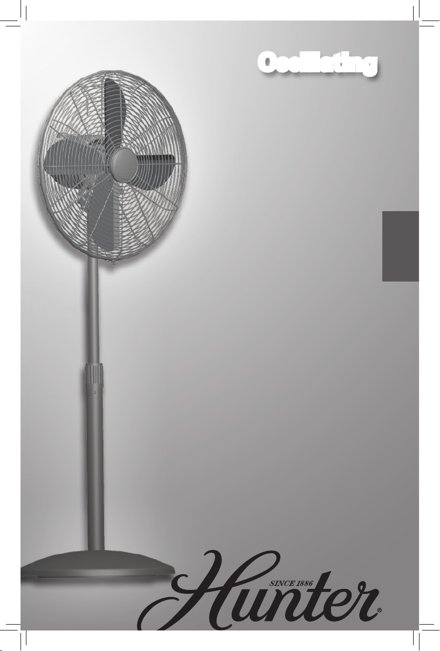
Stand Fan
Owner’s Manual
English
Form# 44086-01
20101102
©2010 Hunter Fan Co.
Model
90405
90434
90435
Page 2
TABLE OF CONTENTS
Introduction ............................................................. 3
Safety and Warnings ................................................ 3
Grounding ............................................................... 5
Fused Plug ............................................................... 6
Unpacking ............................................................... 7
Base Assembly ......................................................... 7
Motor Assembly ....................................................... 8
Grill Assembly ......................................................... 9
Operation.............................................................. 11
Off / Speed Selection 11
Oscillation 11
Adjustment 11
Maintenance .......................................................... 12
Technical Support ................................................... 13
Warranty ............................................................... 13
Products ................................................................ 15
©2010 Hunter Fan Co. 44086-01 20101102
2
Page 3
INTRODUCTION
Thank you for choosing the Hunter Oscillating Stand
Fan. This manual gives you complete instructions for
assembling and using your fan. Here are some the
features you will enjoy with your fan:
3 An attractive design that enhances any decor
3 A powerful motor for maximum air flow
3 Three speeds to adjust your comfort level
3 All metal construction
SAFETY AND WARNINGS
To reduce the risk of fire or electrical shock, DO NOT use
this fan with any solid-state speed control device.
When using electrical appliances, basic precautions
should always be taken to reduce the risk of fire, electric
shock and personal injury:
Read all instructions before using this fan.
1. Improper installation may result in the risk of fire,
electric shock or personal injury.
2. To prevent the risk of fire and electric shock, DO
NOT use the unit near windows. Rain and moisture
may create an electrical hazard.
3. The power plug must be removed from the power
socket when not in use, before cleaning, servicing,
maintenance and before moving to another location.
4. DO NOT put fan in a damp place or where humidity
is high-such as a bathroom.
5. The fan should be placed on a flat, stable surface or
tabletop to avoid overturning.
6. Use fan only for intended use, as described in this
instruction manual.
7. To protect against electrical shock, DO NOT immerse
unit, plug or cord in water or spray with liquids.
8. Close supervision is necessary when any appliance
is used by or near children.
9. NEVER insert fingers, pencils or any other objects
©2010 Hunter Fan Co. 44086-01 20101102
3
Page 4
through the grill when the fan is running.
10. DO NOT operate any appliance with a damaged
cord or plug, after the appliance malfunctions or has
been dropped or damaged in any manner.
11. To disconnect, grip plug and pull from wall outlet.
NEVER yank on cord.
12. ALWAYS use on a dry surface.
13. This product is intended for household use only and
not for commercial or industrial use.
14. DO NOT operate fan in the presence of explosive
and/or flammable fumes.
15. DO NOT place fan or any parts near an open flame,
cooking or any other heating appliances.
16. DO NOT use near curtains, plants, window
treatments, etc.
17. This appliance has a grounded three-prong plug
and is suitable for grounded receptacle use only.
An adapter is available for connecting three-blade
grounding-type plugs to two-slot receptacles. The
adapter must be properly grounded. DO NOT
attempt to defeat the purpose of this safely feature.
18. The rubber ring on this product may interact with
wood and cause damage to furniture. Do not place
on fine wood furniture.
©2010 Hunter Fan Co. 44086-01 20101102
4
Page 5
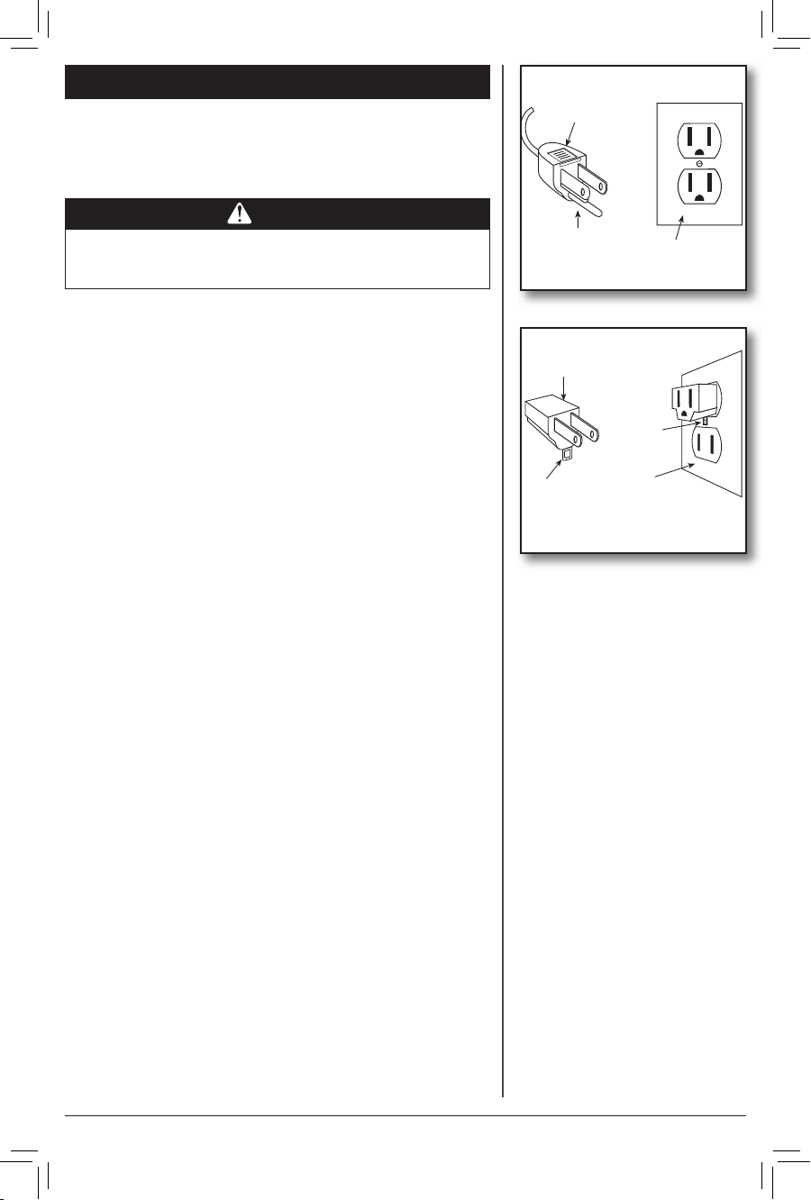
Grounded
GROUNDING
is appliance is for household use only and may be plugged
into any 120-volt AC electrical outlet (ordinary household current). DO NOT use any other type of outlet.
WARNING
is unit is suitable for grounded receptacle use only.
Plug
Grounding Pin
Grounded Outlet
Box Cover
The power cord has a grounded plug as shown in Figure
1, and must be used with an electrical outlet that can
accommodate the grounding pin. If your electrical outlet
can not accommodate the grounding pin, then you must
purchase and install one of the two types of adapters
shown in Figure
NOTE: The adapters ARE NOT supplied with this fan.
Read, follow, and save the instructions that are included
with the adapter you choose. Do not use an adapter if
your electrical outlet can accommodate the grounding
pin.
LINE CORD SAFETY TIPS
1. NEVER pull or yank on the cord or the appliance.
2. To insert plug, grasp it firmly and guide it into the outlet.
3. To disconnect the appliance, grasp the plug and remove it
from the outlet.
4. Before each use, inspect the line cord for cuts and/or
abrasion marks. If any are found, the appliance should be
serviced and the line cord replaced. Please return it to our
Service Department or to an authorized service representative.
5. NEVER wrap the cord tightly around the appliance, as this
could place undue stress on the cord where it enters the appliance and could cause it to fray and break.
6. DO NOT operate appliance if the line cord shows any dam-
age, if the appliance works intermittently or stops working
entirely.
Adapter
Grounding
Means
Metal
Screw
Grounded Outlet
Box Cover
Figure 1.
Figure 2.
©2010 Hunter Fan Co. 44086-01 20101102
5
Page 6
FUSED PLUG
This plug is a safety feature. It contains a safety device
(fuse) that should not be removed. Discard product if the
attachment plug is damaged. To reduce the risk of fire,
electric shock and personal injury, DO NOT remove,
replace, repair or tamper with the originally supplied
plug. If the Fan does not function properly, it may be due
to the safety device incorporated in this plug.
If the fuse fails, it is generally due to a short circuit or
circuit overload. Replace the fuse as per the instructions
below. If the replacement fuse fails, immediately
unplug the unit and contact our technical support
department for assistance.
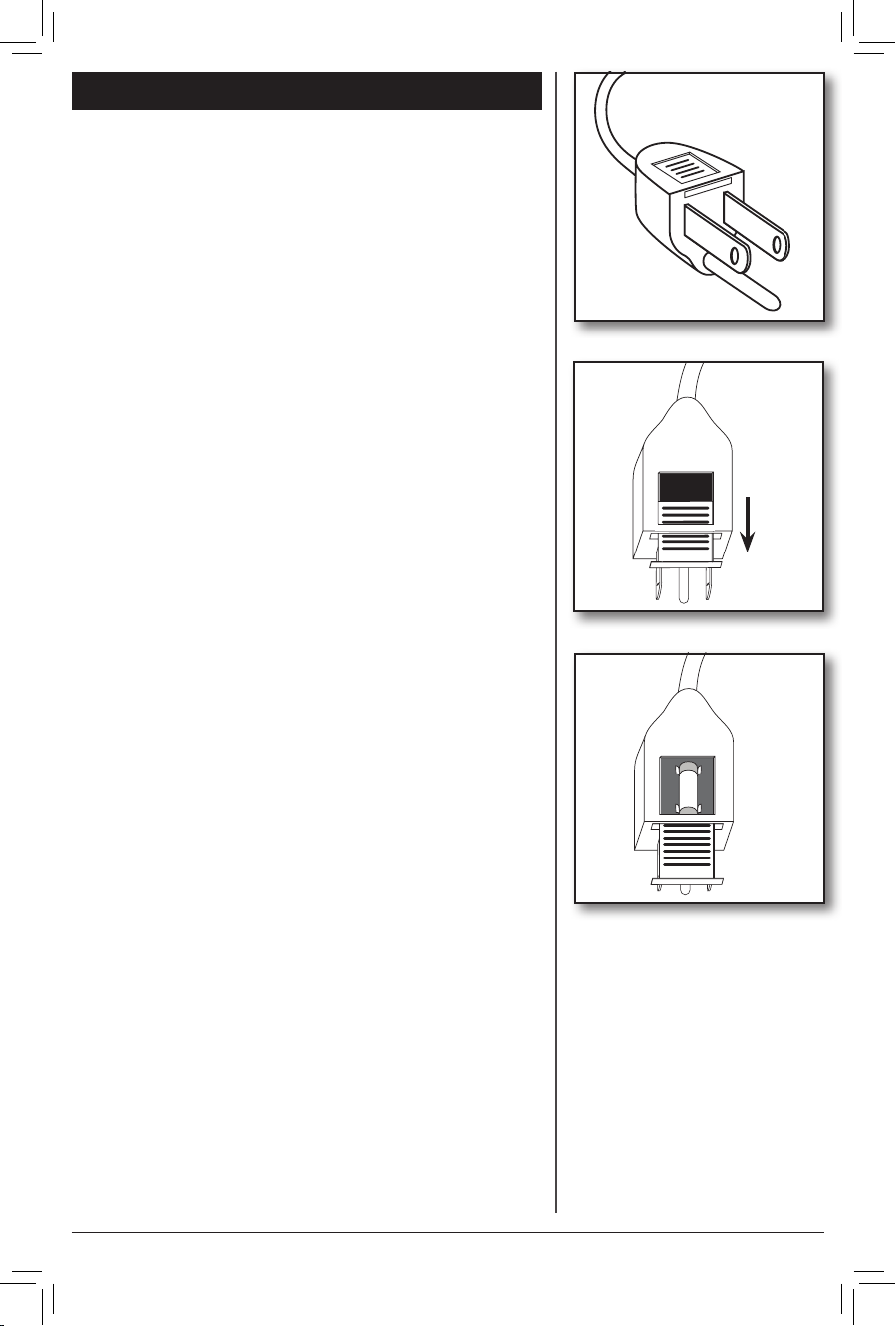
Fuse Replacement:
1. To replace the fuse, first turn the unit it off and unplug
it from the wall. Locate the door on top of the plug.
Figure 1.
2. Slide the door on top of the plug towards the blades.
Figure 2.
3. Carefully remove the fuse from the clips holding it on
the top and bottom. Figure 3.
Warning! Electrical Hazard! Only replace with a
fuse type and rating matching what was removed from
the product.
4. Gently push the fuse back into the pins that will hold
it in place.
Figure 1.
Figure 2.
Note: If the fuse is not seated properly, the unit will not
function.
5. Slide the Door back over the fuse box in the plug.
6. Plug the fan back in and resume use.
©2010 Hunter Fan Co. 44086-01 20101102
6
Figure 3.
Page 7
UNPACKING
As you unpack the fan, save the carton and packing
materials in case you want to move or ship the unit in the
future. Carefully remove all items from the box.
NOTE: It is best to have someone hold the box while
you lift the fan and the protective packaging out of the
carton. Make sure all shipping materials are removed
from fan before operating.
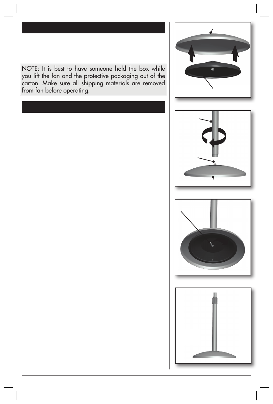
(2) Base Cover
(1) Base Weight
BASE ASSEMBLY
1. Insert the Weight(1) into the Base Cover(2). Figure 3.
2. Insert the base of the Telescoping Pole(3) into the top
of the Base Cover(2) and attach to the Base Weight(1)
by turning clockwise on the Screw(4) in the center of
the Base Weight(1). Figure 4.
3. Turn the Base on it’s side and turn the handle of the
Screw(4) on the bottom of the Weight until secure.
Figure 3.
4. Tip the Base back upright. Figure 5.
Figure 3.
(3) Telescope
Pole
(4) Screw
(2) Base Cover
Figure 4.
(4) Screw
Figure 5.
Figure 6.
©2010 Hunter Fan Co. 44086-01 20101102
7
Page 8
MOTOR ASSEMBLY
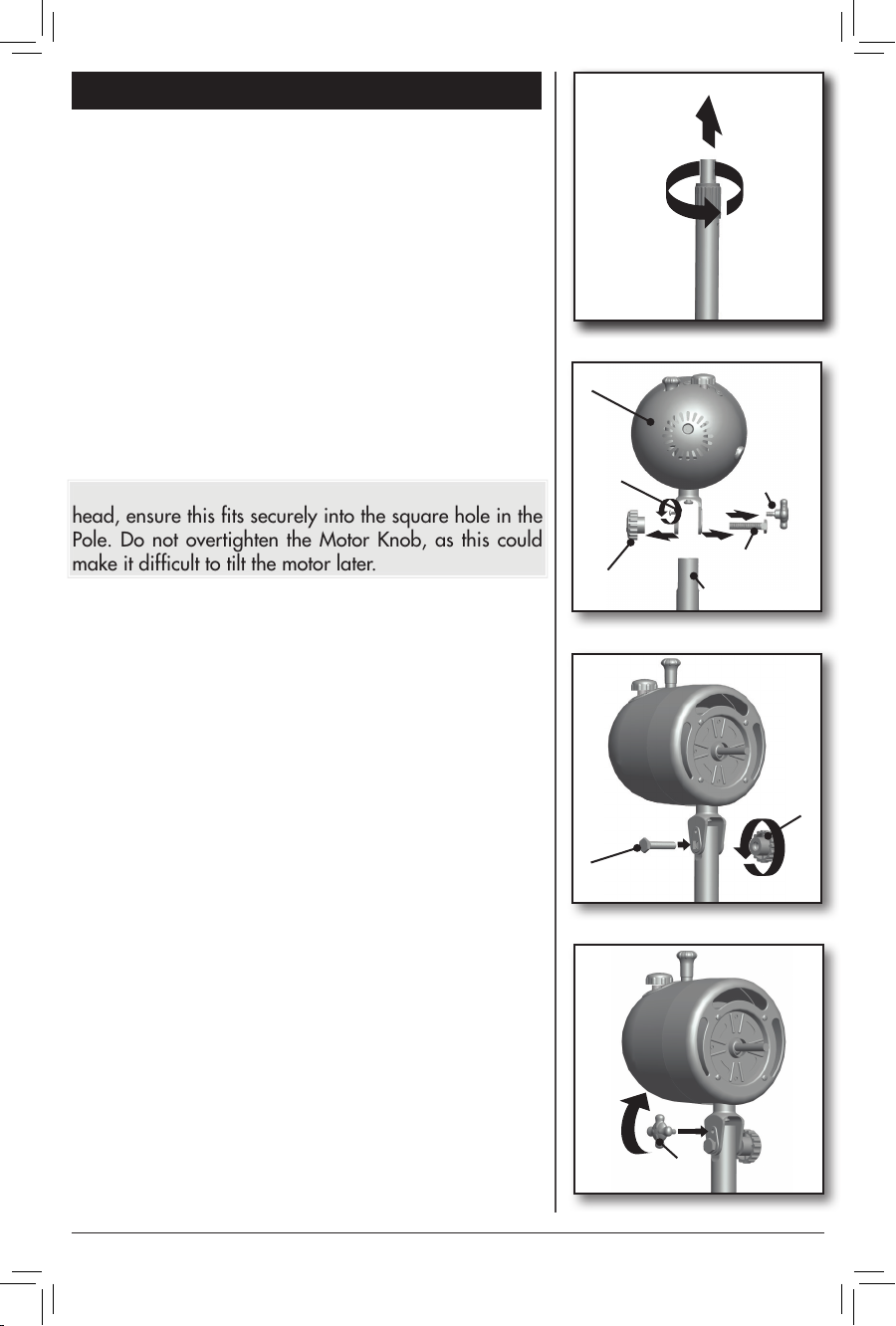
1. Grasp the Telescope Pole firmly and twist the
Adjustment Knob Counter Clockwise to loosen.
Figure 7.
2. Raise the Inner Pole and tighten the Adjustment Knob
by twisting Clockwise until secure.
3. Remove the Motor Knob(7), Motor Bolt(6), and Tilt
Adjustment Knob(8). Loosen the screw above the
Motor Knob(7).
4. Set the Motor(5) on top of the Pole(3), Figure 8.,
and Secure using the Motor Bolt(6) and Knob(7).
Retighten the screw above the motor knob in the slot
to secure motor. Figure 9.
Note: The Motor Bolt has a square cut on the inside of the
head, ensure this fits securely into the square hole in the
Pole. Do not overtighten the Motor Knob, as this could
make it difficult to tilt the motor later.
After securing the motor(5), Screw in the Tilt Adjustment
Knob(8) securely. Figure 10. This Knob allows you to
adjust the fans angle.
(5) Motor
Screw
(7) Motor
Knob
Figure 7.
(8) Tilt
Adjustment
Knob
(6) Motor
Bolt
(3) Telescope Pole
Figure 8.
(7) Motor
Knob
(6) Motor
Bolt
Figure 9.
(8) Tilt Adjustment
Knob
Figure 10.
©2010 Hunter Fan Co. 44086-01 20101102
8
Page 9
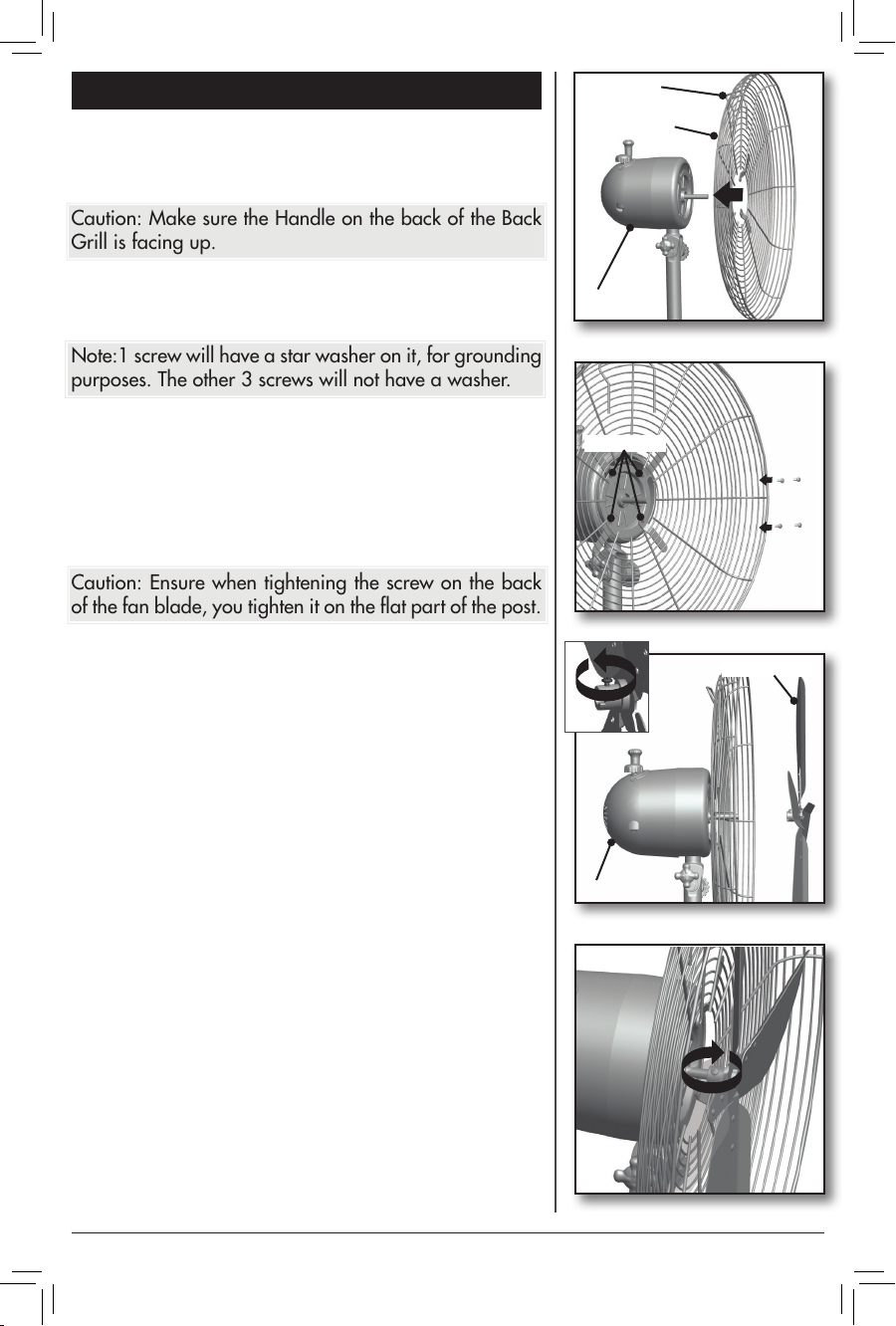
GRILL ASSEMBLY
Handle
1. Place the back grill against the motor housing(5),
Figure 11., and line up the 4 tabs on the back of the
grill(9) to the 4 screws holes on the front of the motor.
Caution: Make sure the Handle on the back of the Back
Grill is facing up.
2. Attach the Back Grill(9) to the Motor(5) using the 4
Grill Mount Screws. Figure 12.
Note:1 screw will have a star washer on it, for grounding
purposes. The other 3 screws will not have a washer.
3. Loosen the Screw on the back of the Fan Blade(10),
13a., and slide the Fan Blade onto the post on the
Motor(5). Figure 13.
4. Tighten the Screw on the Blade(10( to secure it to the
Motor(5). Figure 14.
Caution: Ensure when tightening the screw on the back
of the fan blade, you tighten it on the flat part of the post.
(9) Back Grill
(5) Motor
Screw Holes
13a.
Figure 11.
Figure 12.
(10) Fan Blade
(5) Motor
Figure 13.
Figure 14.
©2010 Hunter Fan Co. 44086-01 20101102
9
Page 10
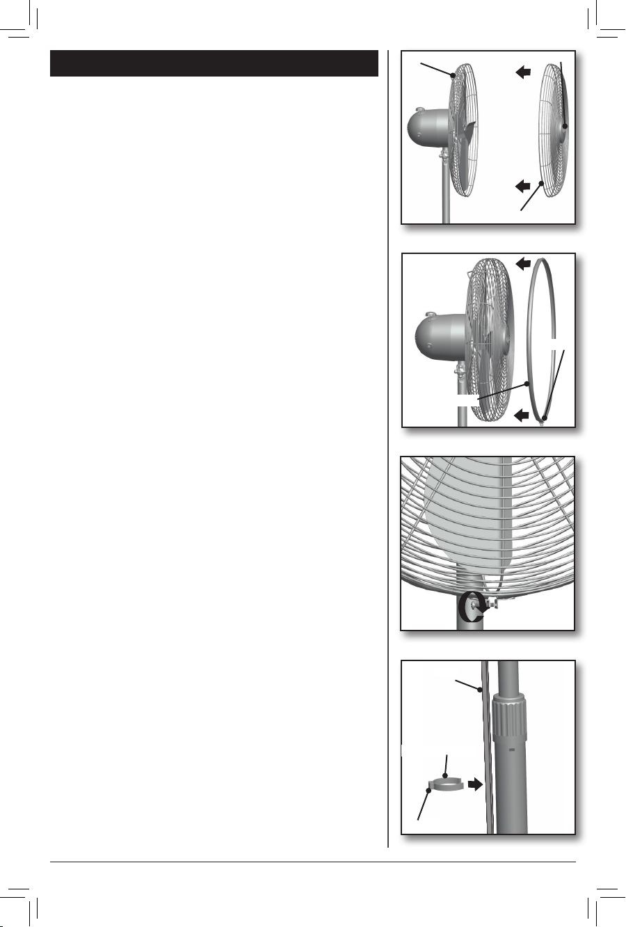
GRILL ASSEMBLY CONT.
1. Remove the Grill Ring from the Front Grill(11) by
loosening the screw holding it.
2. Place the Front Grill(11) against the Back Grill(9) so
the Hunter logo faces right side up and push together
until the tabs on the grills hold them together. Figure
15.
(9) Back Grill
Hunter Logo
3. Slide the Grill Ring over both Front(11) and Back(9)
Grills turning it so the screw that will secure it is on
the bottom. Figure 16.
4. Tighten the Screw to secure the Grill Ring over the
Front and Back Grills.
5. Straighten the Cord from the Motor along the
Telescoping Pole and Snap the Cord Clip over the
cord onto the Pole so the cord rests in the notch on
the Clip. Figure 18.
(11)Front Grill
Figure 15.
Screw
(12) Grill Ring
Figure 16.
Figure 17.
Cord
(13) Cord Clip
Notch
Figure 18.
©2010 Hunter Fan Co. 44086-01 20101102
10
Page 11
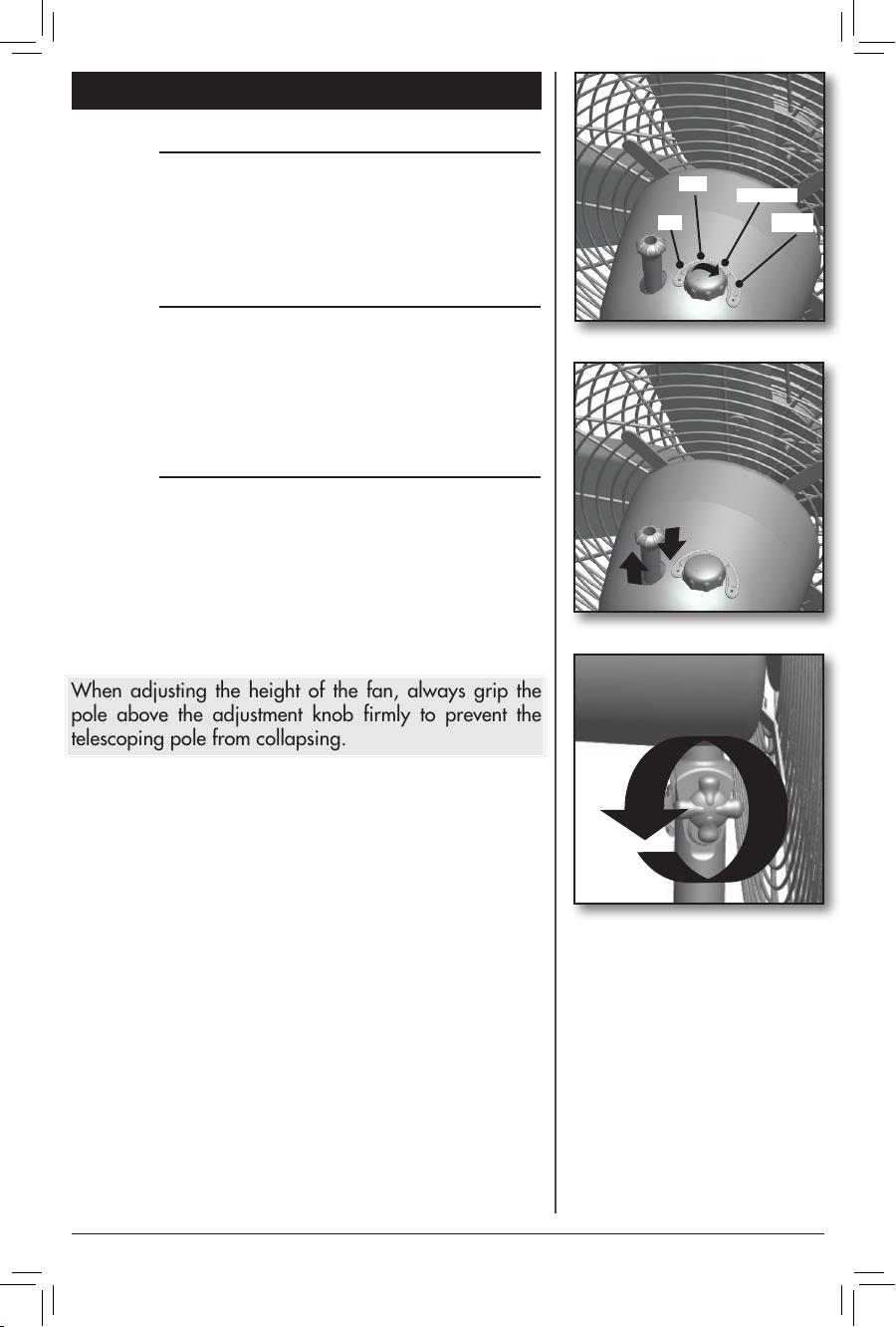
OPERATION
Off / Speed Selection
To turn the fan on and off / control the speed. Turn the
speed knob on the top of the motor to the porper setting.
Figure 19.
Oscillation
To allow the fan to oscillate, push the Knob beside the fan
speed control down. Pull up on the knob if oscillation is
not desired. Figure 20.
Adjustment
To adjust the angle the fan is blowing.
1. Loosen the adjustment knob under the Fan Motor
2. Adjust the fan to the angle desired and retighten the
knob to secure the fan at that angle. Figure 21.
When adjusting the height of the fan, always grip the
pole above the adjustment knob firmly to prevent the
telescoping pole from collapsing.
Off
Low
Medium
High
Figure 19.
Figure 20.
Figure 21.
©2010 Hunter Fan Co. 44086-01 20101102
11
Page 12
MAINTENANCE
This fan is permanently lubricated and will not require
additional lubrication (oil) for the life of the fan.
This fan requires little maintenance and contains
no user serviceable parts. DO NOT try to fix
it yourself. Contact qualified service personnel
if servicing is needed.
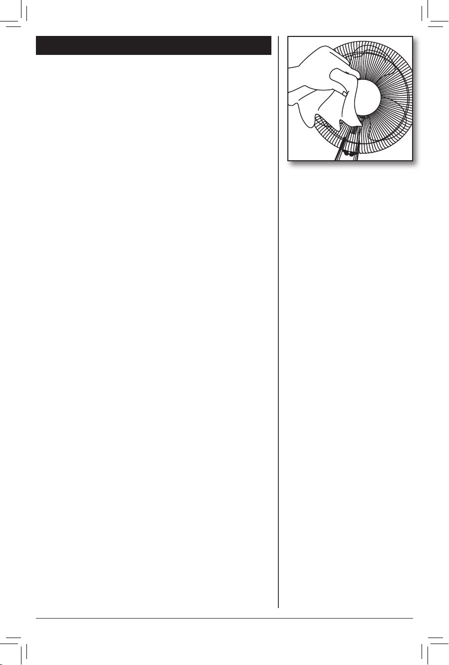
Before cleaning, turn fan off and unplug from electrical
outlet. Wipe off excess dust with a lintfree cloth. To ensure
adequate air circulation to the motor, keep vents located at
the rear of the motor housing free from dust accumulation.
A vacuum cleaner hose can be used to clean these vents.
DO NOT immerse the fan in water or any other liquid.
CLEANING THE GRILL AND BLADE:
1. Turn the fan off and unplug from the electrical outlet.
2. Disassemble the grills by Loosening the screw holding
the grill ring and remove it from the grills.
3. Two tabs hold the Front Grill and Back Grill together.
Pull the Front Grill forn the back.
4. The blade may be removed by loosening the screw
holding it in place. Grills and blades may be cleaned
with mild soap and water only after they have been
removed from the motor housing.
5. Use a dry or slightly damp lint free cloth to clean
the fan. Use a soft, slightly damp cloth to wipe the
remaining fan parts.
3 DO NOT allow water or any other liquid to get into
the motor housing or base.
3 Reassemble the fan after blades and grills have dried
completely.
3 DO NOT plug the fan into an electrical outlet until it
has been fully reassembled.
©2010 Hunter Fan Co. 44086-01 20101102
12
Page 13
1. Problem
Warranty
3 Fan will not oscillate.
Solution
3 Push down on the knob on top of motor housing to
activate oscillation.
2. Problem
3 Can not adjust the angle of the fan.
Solution
3 Loosen the adjustment knob, tilt the fan, then retighten
adjustment knob.
TECHNICAL SUPPORT
If you have any additional questions or problems with
your Hunter Portable Fan, please call:
USA: 1-888-830-1326
Canada: 1-866-268-1936
Hours of operation are from 7:00 am to 7:00 pm
Monday - Friday and 8:00 am to 5:00 pm on Saturday,
Central Time. You may also contact us over the Internet at
www.hunterfan.com.
WARRANTY
The Hunter Fan Company makes the following limited
warranty to the user or consumer purchaser of this Hunter
Portable fan:
If your Hunter Portable Fan motor fails at any time within
five years after the date of sale to you due to a defect in
material or workmanship, labor to repair the defect will
be provided free of charge at our nearest service center
or our Service Department in Memphis, Tennessee. You
will be responsible for labor costs after this one-year
period. The foregoing limited warranty applies only to
the motor itself, and does not apply to electronic controls
such as remote controls, remote control receivers or
transmitters used in conjunction with the motor. These
electronic control items are included in the one year
limited warranty below.
If any part of your Hunter Portable Fan other than the
motor fails at any time with five year after the date of
©2010 Hunter Fan Co. 44086-01 20101102
13
Page 14

Warranty
sale to you due to a defect in material or workmanship,
we will repair or, at our option, replace the defective
part free of charge for parts and labor performed at our
nearest service center or at our Service Department in
Memphis, Tennessee.
IF THE USER OR CONSUMER PURCHASER CEASES TO
OWN THE FAN, THIS WARRANTY AND ANY IMPLIED
WARRANTY WHICH THEN REMAINS IN EFFECT,
INCLUDING BUT NOT LIMITED TO ANY IMPLIED
WARRANTY OF MERCHANTABILITY OR FITNESS FOR A
PARTICULAR PURPOSE, ARE VOIDED. NO WARRANTY,
EXPRESSED OR IMPLIED, INCLUDING ANY WARRANTY
OF MERCHANTABILITY OR FITNESS FOR A PARTICULAR
PURPOSE, IS MADE IN RESPECT TO THE GLASS GLOBES
OR LIGHT BULBS OR THE FINISH ON ANY METAL
PORTION OF THE FAN. THIS WARRANTY IS IN LIEU
OF ALL OTHER EXPRESS WARRANTIES. THE DURATION
OF ANY IMPLIED WARRANTY, INCLUDING, BUT
NOT LIMITED TO ANY IMPLIED WARRANTY OF
MERCHANTABILITY OR FITNESS FOR A PARTICULAR
PURPOSE, IN RESPECT TO ANY HUNTER FAN MOTOR
OR OTHER FAN PART, IS EXPRESSLY LIMITED TO THE
PERIOD OF THE EXPRESS WARRANTY SET FORTH
ABOVE FOR SUCH MOTORS AND OTHER PARTS.
This warranty is voided if your Hunter Fan is not
purchased and used in the USA.
This warranty excludes and does not cover defects,
malfunctions or failures of any Hunter Portable fan
which were caused by repairs by persons not authorized
by us, use of parts or accessories not authorized by
us, mishandling, improper installation, modifications,
or damage to the Hunter Portable fan while in your
possession, or unreasonable use, including failure to
provide reasonable and necessary maintenance.
To obtain servicing, contact the nearest Hunter authorized
service center or the Hunter Fan Company Service
Department, 7130 Goodlett Farms Pkwy. Suite 400,
Memphis, Tennessee 38016. Please contact us before
shipping your fan to us. If we authorize you to ship it to
us, you will be responsible for all insurance and freight
or other transportation charges to our factory service
center. We will return your Hunter Fan freight prepaid.
Your portable fan should be properly packed to avoid
damage in transit since we will not be responsible for
©2010 Hunter Fan Co. 44086-01 20101102
14
Page 15
Warranty
any such damage. Proof of purchase is required when
requesting warranty service. The purchaser must present
sales receipt or other document that establishes proof of
purchase.
IN NO EVENT SHALL HUNTER FAN COMPANY BE
LIABLE FOR CONSEQUENTIAL OR INCIDENTAL
DAMAGES.
SOME STATES DO NOT ALLOW LIMITATIONS ON
HOW LONG AN IMPLIED WARRANTY LASTS OR
THE EXCLUSION OR LIMITATION OF INCIDENTAL
OR CONSEQUENTIAL DAMAGES SO THE ABOVE
LIMITATION MAY NOT APPLY TO YOU.
THE WARRANTY GIVES YOU SPECIFIC LEGAL RIGHTS
AND YOU MAY ALSO HAVE OTHER RIGHTS WHICH
VARY FROM STATE TO STATE.
PRODUCTS
Fan Company
7130 Goodlett Farms Pkwy., Suite 400
Memphis, Tennessee 38016
Printed in china and Taiwan
©2010 Hunter Fan Co. 44086-01 20101102
15
To learn more about Hunter
Fan Company products,
please see our Web page at:
www.hunterfan.com
 Loading...